Article

Application of New High-Energy Expansion Agent in Coal Mine Roadway Excavation

1
College of Safety and Environmental Engineering, Shandong University of Science and Technology, Qingdao 266590, China
2
Hubei Sunvalor Power Source Aerospace Tech Co., Ltd., Xiangyang 441003, China
*
Author to whom correspondence should be addressed.
Processes 2023, 11(5), 1356; https://doi.org/10.3390/pr11051356
Submission received: 31 March 2023 / Revised: 15 April 2023 / Accepted: 26 April 2023 / Published: 28 April 2023
(This article belongs to the Section Materials Processes)

Abstract

:
A new energy material, a high-energy expansion agent (HEEA), was proposed for the harsh engineering environment of a mine. A safety test and field engineering test were carried out. The results showed that the mechanical sensitivity of the HEEA was extremely low, and no combustion and explosion occurred in multiple impact and friction tests. Meanwhile, the HEEA only burns in open spaces without detonation. Through field experiments, the HEEA can achieve a good blasting effect, providing strong support for its promotion in low-disturbance environmental engineering applications.

1. Introduction

Safe and effective rock crushing is of great significance in municipal, mining and hydropower projects [1,2,3]. Underground rock engineering construction projects, such as tunnels, roadways and shafts, usually involve blasting excavation of rock mass [4]. In recent years, explosive blasting has developed rapidly. A large number of researchers have conducted in-depth research on the rock-breaking law of explosives and recognized it as the most efficient rock-breaking technology. However, its disadvantages are also recognized by everyone, such as large blasting noise and vibration [5,6,7], and the approval procedures and storage and transportation process are cumbersome. Therefore, this study aims to propose a new rock-breaking technology that is safer than emulsion explosive blasting and more efficient than traditional non-explosion technology.
In recent years, scholars have conducted a lot of research on rock-breaking technology from experimental research, theoretical analysis and numerical simulation [8,9,10,11,12]. K. Iwano et al. [13] used advanced electronic detonators to conduct blasting tests for engineering tunnels. The results showed that the peak amplitude of the blast hole vibration waveform obeys the Weibull distribution, and the propagation time of the wave is related to the position of the blast hole on the roadway working face. Li et al. [14] used the Riedel Heiermaier Thoma (RHT) model to conduct a numerical study of the single-hole blasting process calibrated by field blasting tests and studied the effects of the magnitude of ground stress and the lateral pressure coefficient on the fracture zone and crack growth. Zhang et al. [15] analyzed the blasting effect of L-CO2 blasting technology on the basis of an L-CO2 blasting test and studied the fracture mechanism of the L-CO2 blasting technology from the perspective of the stress wave effect through theoretical analysis and cyclic simulation. Li et al. [16] proposed a new type of liquid carbon dioxide rock-breaking technology and carried out vibration field tests and field rock-breaking tests. The experimental results showed that the vertical components of the particle peak vibration velocity during rock fragmentation are 173 mm/s, 85 mm/s and 35 mm/s, respectively, and about 85% of the energy is distributed at 6~60 Hz. Guo et al. [17] conducted a series of fracturing tests through a perforated wellbore under true triaxial stress and analyzed the characteristics of a fracturing treatment pressure curve, the effects of the stress difference and natural fractures on hydraulic fracturing geometry, the perforation failure mode and the differences between calcareous mudstone fracturing and shale fracturing. Natalia Kuznetsova et al. [18] proposed a plasma explosion analysis model, which solved the problem of an insufficient understanding of the dynamics of shock wave generation and propagation and the conditions of electric energy release. Zhao et al. [19] proposed a non-explosive expansion method (NEM) for the exploitation of coalbed methane by reservoir fracturing. The results showed that under different lateral stresses, an NEM with a different crack morphology is used to destroy the specimen, and the fracture evolution depends on the structure and lateral stresses to a large extent, which leads to a complex crack number and crack distribution. Above rock breaking technologies are generally characterized by low safety inspection and efficiency, and some technologies have not been successfully applied in the flat hole construction of tunnels on a large scale.
Therefore, by summing up the advantages and disadvantages of the above rock-breaking technologies, a safe and efficient rock-breaking technology is proposed. The rock-breaking technology is based on a kind of energetic material, a High-Energy Expansion Agent (HEEA), which uses the expansion of high-pressure gas and the detonation of explosives for reference. In this paper, the safety and effectiveness of the HEEA were tested through experiments. In addition, the advantages and limitations of rock-breaking technology with a HEEA are discussed.

2. Experimental Research

2.1. Materials

Figure 1 shows a high-energy expansion agent sample, which is divided into two types: High-Energy Expansion Agent-A (HEEA-A) and High-Energy Expansion Agent-B (HEEA-B). It is mainly composed of a combustible (coal powder and aluminum powder), oxidant (KNO3), speed control agent (CuCr2O4), binder (methyl silicone oil) and plasticizer (C26H50O4).
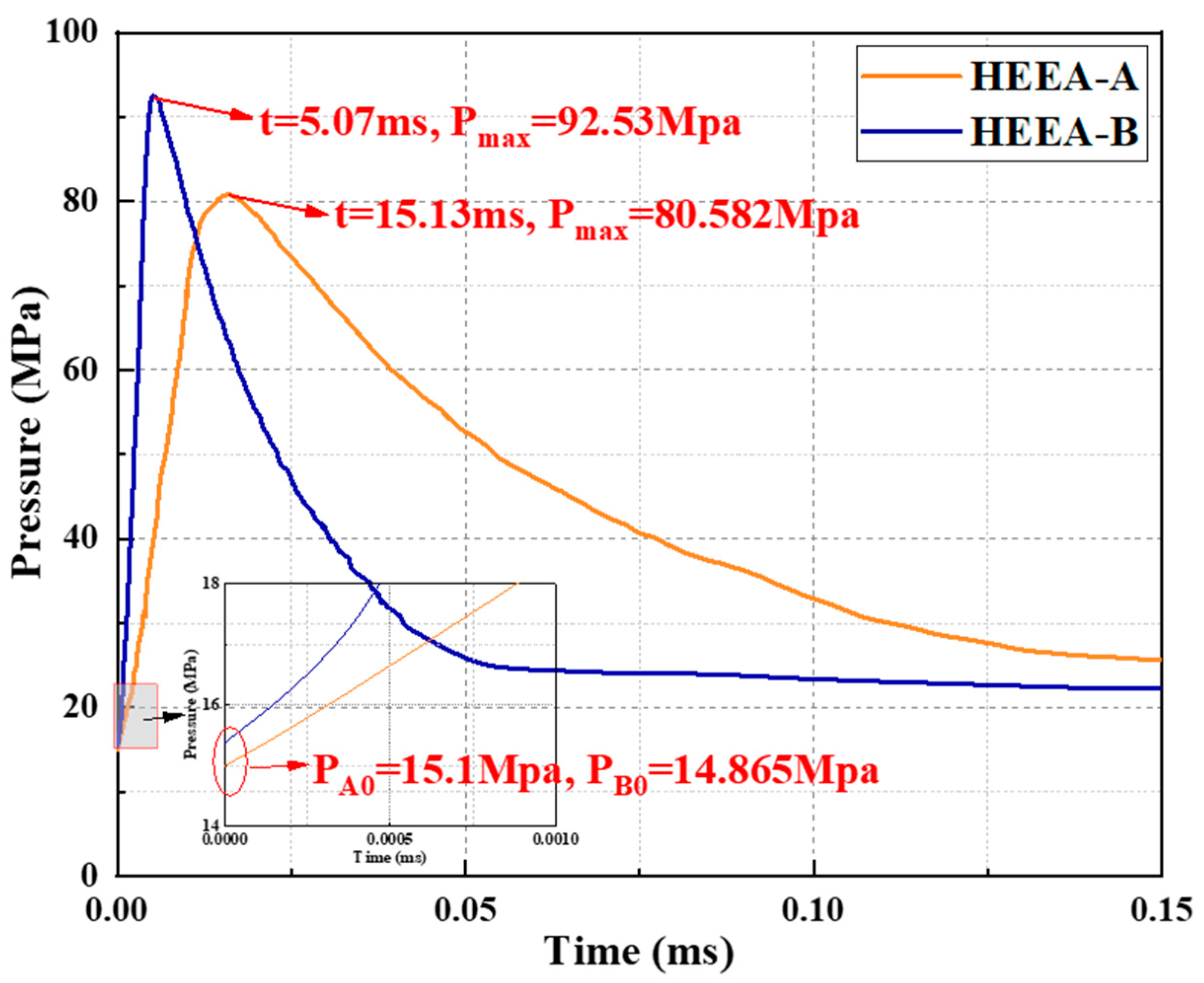
The agent acts on the rock mass in two stages. First, the rapid combustion produces a large amount of gas. The quasi-static pressure of the high-pressure gas causes the crack and the expansion of the rock fracture pores. In the second stage, the unburned explosive detonates instantaneously, and the detonation wave couples with the high-pressure gas to form a large-range fissure network. Due to the innovation of the energy release mode, the influence range of the fracture network in the rock mass is 10~15 times that of the fracture pore formed by traditional blasting. The deflagration pressure of HEEA was tested according to the standard GJB770B-2005, and the test charge was 5 g. The data are shown in Figure 2.
The time required to reach the peak pressure was 15.13 ms and 5.07 ms for HEEA-A and HEEA-B, respectively, with detonation pressures of 15.1 MPa and 14.865 MPa and peak pressures Pmax of 80.582 MPa and 92.006 MPa. Under the same reagent quality, the peak pressure of HEEA-B is 14~18% higher than that of HEEA-A, and the difference in the time to reach the peak pressure is about 10 ms, but the initiation pressure of the HEEA is relatively large. The energy and work capacity of HEEA-B will be larger than that of HEEA-A, and the detonation energy required by HEEA-B will be lower. This also means that under the same conditions, the work process and ability of reagent B are faster and stronger. This is related to the different types of combustible agents in the HEEA. The combustible agent in HEEA-A is coal powder, and the combustible agent in HEEA-B is aluminum powder. From the nature of the powder itself, it can be seen that aluminum powder has higher energy in common combustible dust, which is obviously different from the explosion energy of pulverized coal. Therefore, the HEEA with different formulations will produce energy gradients. According to the special combustion principle and action process of the agent, the deflagration pressure and energy will rise rapidly with the change in gas production and the rise in temperature in the explosive, so the actual rock-breaking method and work capacity need to be further tested and verified.

2.2. Security Testing

2.2.1. Mechanical Sensitivity

According to the standard GJB770B-2005, the impact sensitivity and friction sensitivity of the High-Energy Expansion Agent were tested 25 times, respectively, and they were all decomposed or burnt. The mechanical sensitivity of high-energy expanders is low because the binders and plasticizers in the components can absorb heat, which can weaken or prevent the generation and propagation of heat sources. At the same time, a layer of firmly adhered lubricating transfer film is formed on the surface of the sample particles to reduce the friction between the particles and between the particles and the external environment and avoid the generation of friction heat sources to absorb most of the energy when the sample is hit by a falling hammer. The reducing agent and oxidant reduce the energy absorption, thereby reducing the ignition rate of the sample and ensuring safety in the process of reagent production, storage and transportation.

2.2.2. Moisture Content and Hygroscopicity

The oxidant in the HEEA is mainly potassium nitrate, which will agglomerate in humid air. Of course, water will become steam when the agent is burned, strengthening the rock-breaking ability. However, with the increase in the water content, the properties of the agent will be affected to some extent, and it will be impossible to ignite it. Therefore, it is necessary to test the hygroscopicity of the agent to determine the normal service life of the agent. The hygroscopicity is generally expressed by the water content.
This study tested the moisture content of two kinds of dried HEEA under open and closed conditions. The test environment was the daily air environment, with an average maximum temperature of 32.3 °C and an average minimum temperature of 24.9 °C. Based on the water content data of the HEEA for 30 days, the storage effect of the HEEA in open and closed environments was analyzed. The specific operation steps are as follows.
(1)
Dry the HEEA sample for 2 h at 80 °C. Cool for 1 h after drying, weigh the sample and record it. Repeat the above operation. If the mass difference after two drying periods is less than 0.002 g, the HEEA sample is considered to be completely dry.
(2)
Number and weigh the beaker and record it as the beaker mass, M1. Then, weigh about 10 g of dried HEEA sample into the numbered beaker and record its total mass, M2.
(3)
Number and weigh the sealed bag and record it as the mass, M1, of the sealed bag. Weigh about 10 g of dry HEEA into the sealed bag and record its total mass, M2.
(4)
Put the container containing the HEEA samples above in a safe place in the laboratory, and record the total mass M3 of the container and samples at the same time every day for 30 days.
The calculation method of the HEEA water content is shown in Formula (1).
W = M 3 M 2 M 3 M 1 × 100 %
where W is the moisture content of the HEEA sample; M 1 is the mass of the container, g; M 2 is the total mass of the container and the dry sample, g; M 3 is the total mass of the container and the sample, g.
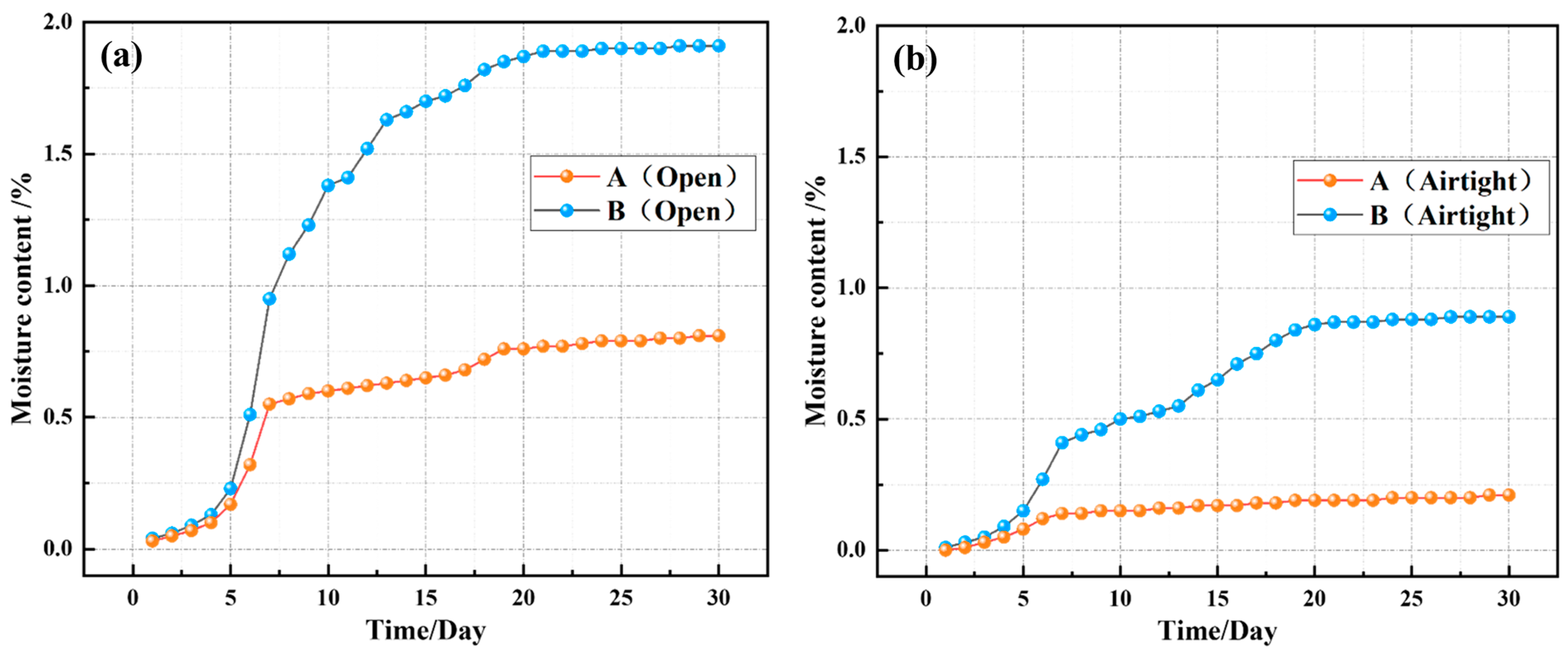
It can be seen from Figure 3a that the water content of HEEA-A is small in the first 5 days in an open environment, and it increases greatly in about 6–8 days. After 9 days, the water content increases slowly and is finally maintained at about 0.81%. In the open environment, the water content of HEEA-B increases slowly in the first 5 days. The water content increases greatly from 6 to 17 days and remains at 1.91% after 17 days. Figure 3b shows that the water content of HEEA-A in the closed state is stable after 18 days and remains at about 0.21%. The hygroscopicity of HEEA-B is obviously reduced in the sealed environment, and the water content is stabilized at about 0.89% in about 20 days. It can be concluded that the moisture absorption rate and moisture content of the two HEEA in the sealed state are significantly reduced, and the sealing has a great improvement on the storage of the HEEA.
The difference in the water content between the two HEEA is due to the different components of the HEEA formula. The oxidant of both HEEA is potassium nitrate, but the main fuel of HEEA-A is pulverized coal. From a microscopic perspective, the surface of pulverized coal is relatively rough and porous. Due to the special surface structure of pulverized coal, potassium nitrate can be adsorbed on the surface of pulverized coal. When potassium nitrate begins to absorb moisture, potassium nitrate particles cannot be agglomerated due to the constraints of coal powder, but with the increase in the HEEA-A storage time, potassium nitrate will still be agglomerated. The main fuel of HEEA-B is aluminum powder. Because the surface of aluminum powder is relatively smooth and has strong fluidity, it is unable to bind potassium nitrate. After mixing potassium nitrate particles with aluminum powder, they are relatively dispersed. After potassium nitrate absorbs water, it makes the potassium nitrate particles become hygroscopic and agglomerate under the adsorption of the water molecules. The agglomerated potassium nitrate promotes the hygroscopicity of the HEEA and further increases the moisture content of the HEEA. Therefore, the HEEA samples stored for more than 30 days are subjected to an ignition test, and the HEEA samples stored in sealed bags can be ignited normally. The HEEA and HEEA-A stored in the open state can ignite normally in 10 pilot tests. However, in the pilot test of HEEA-B, there was a failure in the ignition once. Therefore, storage in a relatively dry environment can make the HEEA have a longer validity period.

3. High-Energy Expansion Agent Technology

3.1. High-Energy Expansion Agent Device Structure

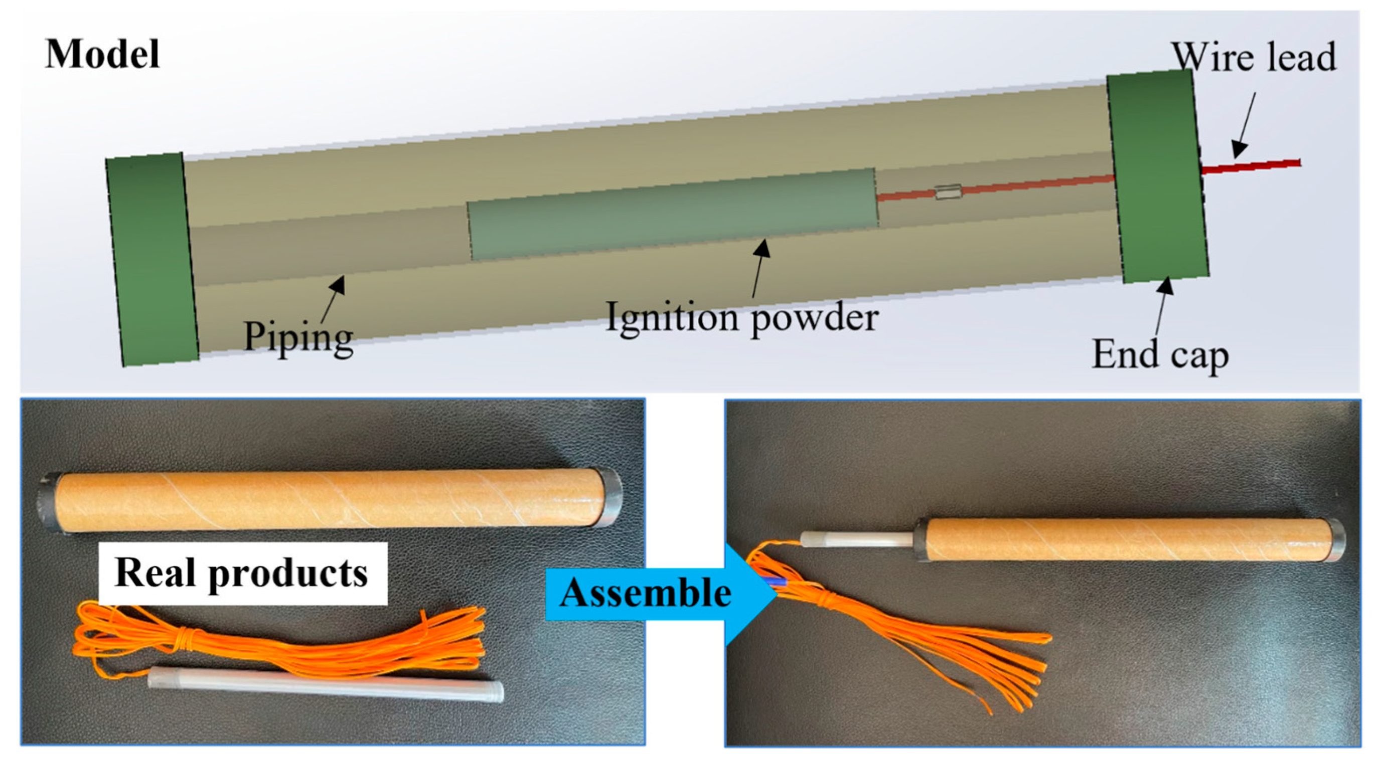
The HEEA is an energetic powder that can quickly burn under high pressure to produce a large amount of high-temperature gas after ignition. The complete product device structure for field application is shown in Figure 4. The overall burning rate of the grain determines the overall energy release power and blasting cracking ability of the grain.

3.2. Ignition Powder

Ignition powder is the most important agent to ensure the successful ignition of the HEEA, which is usually excited by an electric ignition head and then ignites the HEEA. It can be seen from the above research that the HEEA has very low mechanical sensitivity and electrostatic spark sensitivity, which may result in trouble igniting the agent. The HEEA has no detonator sensitivity, and common industrial explosive initiators cannot directly excite the HEEA. Therefore, a new type of ignition agent matching the HEEA is proposed in this research.
The main components of the ignition powder are a coating agent (accounts for 3~9%), an oxidant (accounts for 6~85%), fuel (accounts for 15~25%) and a combustion catalyst (accounts for 1~4%). In the ignition compositions used in this paper, the coating agents are liquid rubber and grease, with a mass fraction of 3.0% each; the oxidants are potassium perchlorate and potassium nitrate, accounting for 55% and 14%, respectively; the fuel is silicon powder, accounting for 24%; and the combustion catalyst is iron oxide, accounting for 1%. There is no metal powder in this ignition composition, so the cost is low, but the ignition is reliable, and it can be directly ignited by an ordinary electric igniter. The friction sensitivity, impact sensitivity, static sensitivity, electrostatic sensitivity and thermal decomposition temperature of the igniter powder are 4%, 5%, 156.5 mJ, 325 °C and 300 °C, respectively, indicating that the safety performance and thermal stability of the igniter powder are good. In addition, the energy released after ignition of the igniter is high, the detonation heat and specific volume reach 4810 J/g, respectively and the burning rate can be controlled at 20~120 mm/s, with a wide adjustable range.
On the other hand, the coating agents used for the ignition powder are liquid rubber and oil ester, which can effectively reduce the mechanical sensitivity of the ignition powder. The oil ester not only plays the role of binder, improves the adhesion between potassium perchlorate and liquid rubber and ensures that potassium perchlorate will not cause sedimentation but also forms a protective film on the surface of the ignition powder to isolate the moisture in the air and reduce the moisture content and moisture absorption of the ignition powder. Potassium perchlorate is the main oxidant because of its high content. The mechanical sensitivity of potassium perchlorate is relatively low, so the mechanical sensitivity of the igniter will be correspondingly low, and the safety performance is good. The burning rate of the ignition powder can be adjusted according to the particle size of potassium perchlorate and potassium nitrate and the content of iron oxide to ensure a large adjustment range of the burning rate of the ignition powder.
Figure 5 shows the test process of the ignition powder igniting the HEEA. The whole ignition process was observed through slow-motion video, which lasted for about 10 s. As shown in Figure 5b, at 0.05 s, the igniter successfully excites and ignites the high-energy expander. It can be seen on site that the high-energy expander burns rapidly in the open space, indicating that the energy of the igniter can ignite the high-energy expander quickly and easily. In Figure 5c, it can be roughly seen that the flame generated by deflagration has covered the whole high-energy expander device, but the flame does not spread to both ends when the PVC pipe bundle is attached, which indicates that the device is designed reasonably, both ends have sufficient binding force and energy leakage and waste will not occur due to device problems. Within 2 s to 10 s, the flame decays rapidly and the generated smoke gradually disappears. At this time, the reaction of the high-energy expander has basically ended. Through the above ignition test, it can be concluded that the igniter device can be detonated normally by the detonator, and for the energy released by the ignition device and the reaction speed, it can reach the ignition conditions of the high-energy expander and stably excite the high-energy expander. At the same time, it can be seen from the whole combustion process of the HEEA that the energy and excitation speed of the new type of igniter are sufficient to meet the ignition conditions of the HEEA. In addition, the HEEA does not explode in the open space, which can further verify the scientificity of the rock-breaking principle of the HEEA. Moreover, the continuous reaction time of the high-energy expander in open space is many times slower than that of ordinary industrial explosives, which can effectively ensure the safety of the high-energy expander in the storage and transportation process.
For commonly used industrial explosives, electronic detonators are required to achieve delayed blasting, and the use of electronic detonators requires checking the system time, recording the detonator, networking and other operations. Although it ensures a certain level of safety, its operation is very cumbersome. At the same time, industrial explosives will explode instantly after initiation, which poses certain safety hazards regarding transportation, storage and use processes. However, after the HEEA excitation, it only burns to produce gas in an open space, and there will be no detonation phenomenon. By utilizing different types of HEEA with different burning rates and ignition powder quantities, segmented blasting can be achieved, ensuring safety and efficiency. This provides scientific theoretical guidance for later engineering applications.

4. Engineering Validation

4.1. Project Overview

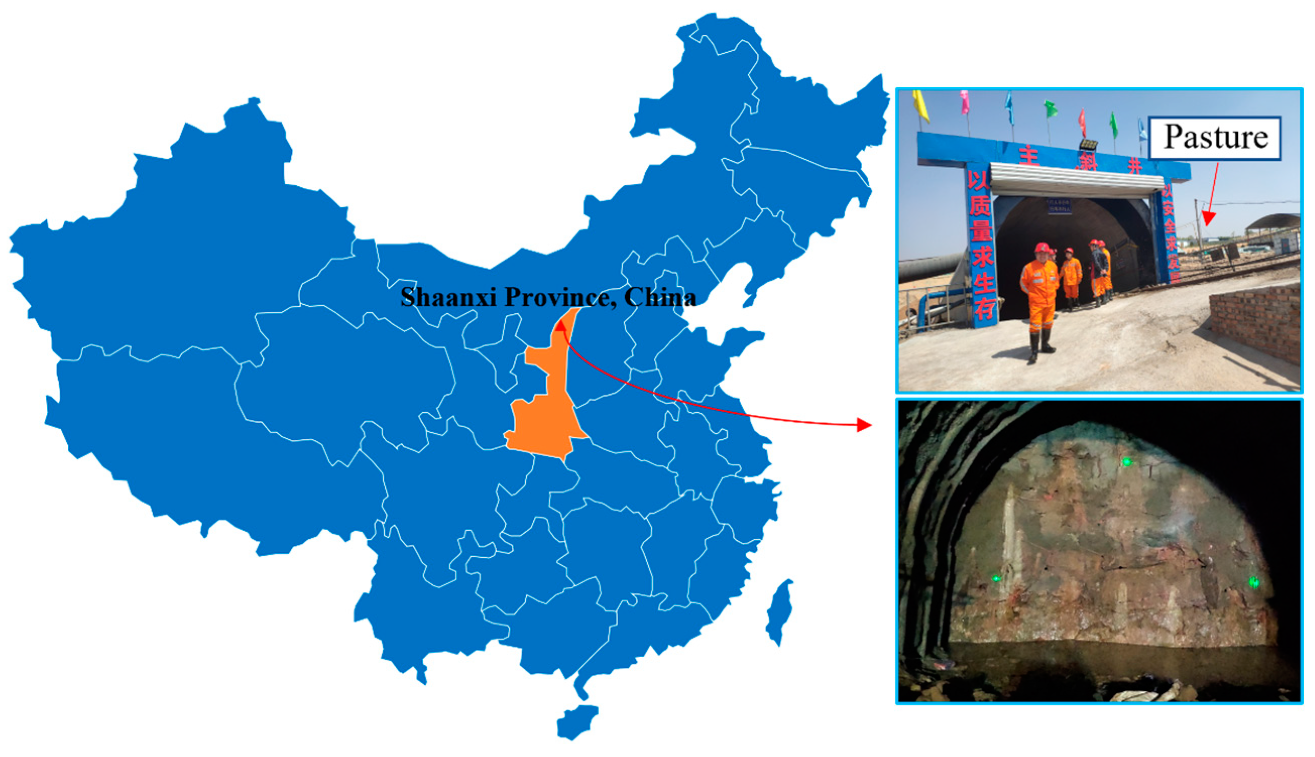
As is shown in Figure 6, the coal mine is located in the third phase planning area of the Yushen mining area of the Jurassic coalfield in northern Shaanxi, China and is under the jurisdiction of the Mengjiawan Township, Yulin City, Shaanxi Province and Dabaodang Town, Shenmu City. The test site is located inside the main inclined shaft. The width of the main inclined shaft roadway is 5.7 m, the height is 5.0 m and the excavation area is about 25 m2. At this time, the main inclined shaft is about 250 m long. The test section passes through the rock stratum mainly as brownish-red medium-grained sandstone, and its hardness coefficient, f, is about 7. At present, the roadway length is 150 m. The slope is 15°. Since there is a pasture above the main inclined shaft of the coal mine, the large vibration noise will cause trouble to herdsmen, and the government has restricted explosive blasting at the construction site. Therefore, the proposed crushing technology with a HEEA has been implemented.

4.2. Test Program

Because this technology is relatively new, in order to facilitate the construction personnel to quickly accept the rock-breaking process, the HEEA design imitates the construction process of explosive blasting, which is mainly divided into the following steps: drilling, charging, hole sealing, connecting and starting. This experiment is divided into two levels of cutting. The depth of the first level cutting hole is 1.5 m, the depth of the second level cutting hole is 2.6 m, the inclination of the cutting hole is 70 ° and the diameter of the drill hole is 38 mm. Two auxiliary cutting holes, the 8 # hole and 12 # hole, are arranged in the cutting area, and the depth of the other blast holes is 2.5 m. See Figure 7 for the specific scheme. Since the delayed ignition charge is not used, the HEEA’s own burning rate difference is used for staged blasting. It can be seen from the P-t test curve of the HEEA above that compared with HEEA-A, HEEA-B has a faster burning rate and greater power, so it uses the difference in the burning rate of the agent and the amount of ignition powder to conduct staged blasting.
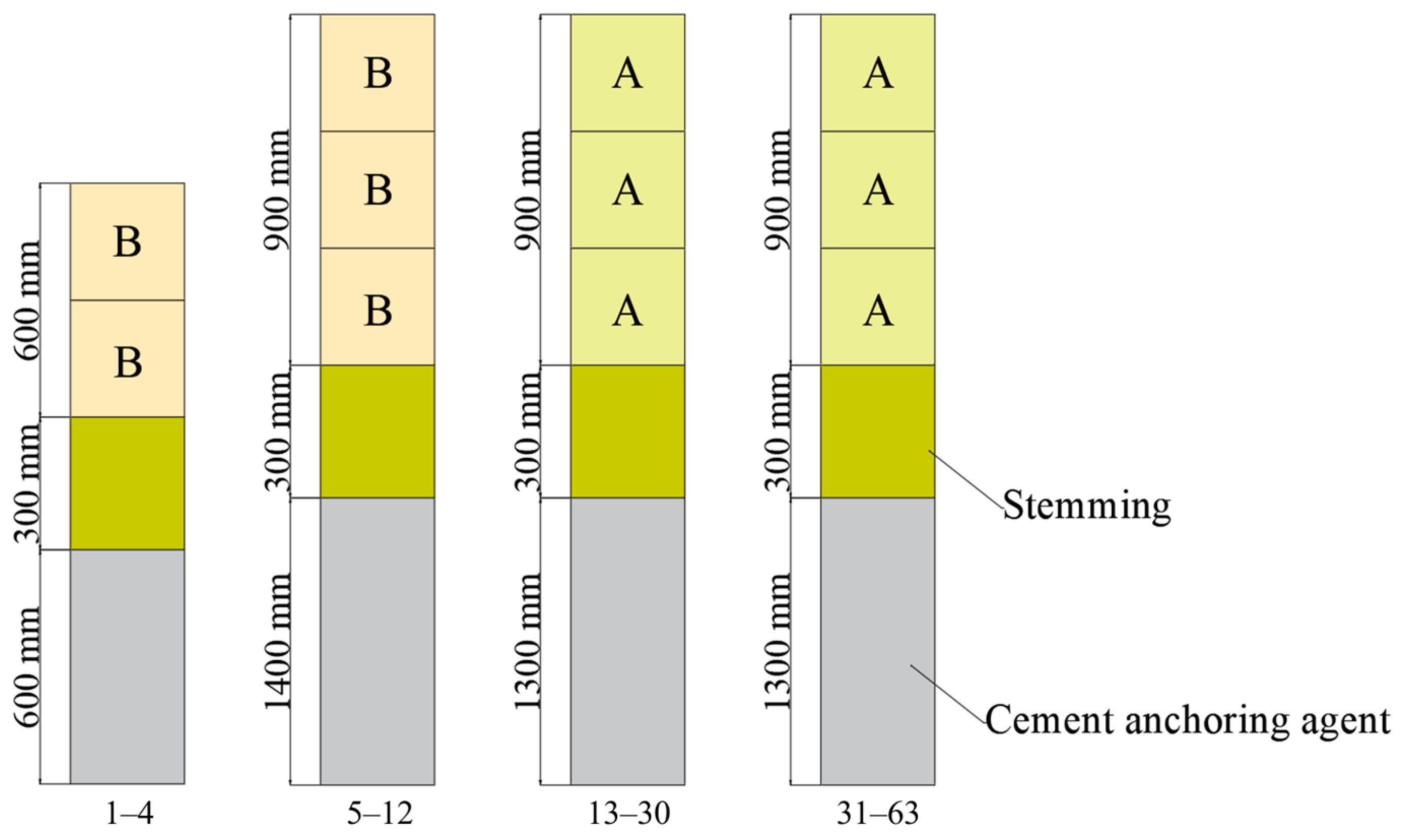
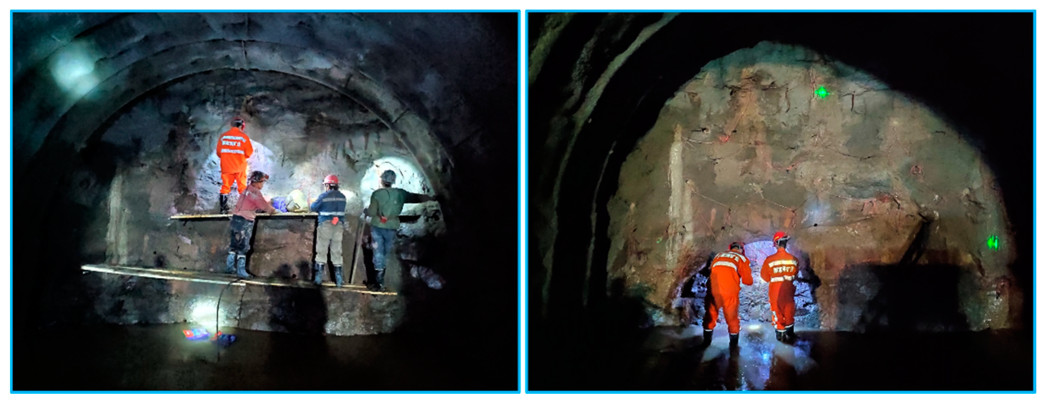
The charge structure is shown in Figure 8, and the charge parameters are shown in Table 1, where A represents a HEEA-A and B represents a HEEA-B. Two pieces of HEEA-B and two pieces of ignition powder are used for the primary cutting hole, and three pieces of HEEA-B and one piece of ignition powder are used for the secondary cutting hole. It is ensured that the ignition speed of the primary cut is faster than that of the secondary cut and that there is enough work capacity to successfully cut. Three pieces of HEEA-A and one piece of ignition powder are used for the auxiliary holes, and two pieces of HEEA-A and one piece of ignition powder are used for the peripheral holes. The ignition sequence is divided into four, namely, the primary cut hole, secondary cut hole, auxiliary hole and peripheral hole. According to the above design, the total number of boreholes is 63. In order to ensure that the HEEA can be successfully loaded into the boreholes and the generated high-pressure gas can fully act on the rock mass, the HEEA grain size is 30 × 300 mm. The construction process is shown in Figure 9.

4.3. Rock Breaking Effect

The blasting effect is shown in Figure 10. The HEEA rock breaking test has a good effect, the blasting section is smooth and flat and the roadway is well formed. The features of depression can be seen in the cutting area, and there is no obvious residual hole. The hole bottom has been completely broken after cleaning with a small excavator, indicating that the quasi-static expansion of the gas in the early stage played a key role. The smooth blasting of the auxiliary holes provides good conditions for the blasting of the peripheral holes, which shows that it is reasonable to use the HEEA’s own burning rate and energy to achieve staged blasting. The surrounding residual hole is about 15 cm, which conforms to the law of rock breaking by blasting. A total of 10 cycles were conducted in the test section, and the total footage was 22.9 m. The average footage is about 2.29 m, and the average hole utilization rate is 91.6%.
Since the block size of the crushed stone has a great impact on the subsequent slag discharge, one of the cycles is selected to measure the block size of the crushed stone in five groups from 0~5 m of the section, and the number of pieces measured each time is 100. The HEEA rock-breaking technology is compared with the emulsion explosive blasting data of the Project Department. Table 2 shows the comparison data. It can be seen from the data in the table that the maximum fragmentation after emulsion explosive blasting is 36.12 cm, and the maximum fragmentation after the HEEA presplitting is 35.42 cm, which is 1.97% less than the maximum fragmentation size during emulsion explosive blasting. From the average blasting fragmentation, the average fragmentation of the explosive blasting is 13.65 cm, and the average fragmentation of the HEEA presplitting is 12.63 cm, which is about 8% less than the average fragmentation after emulsion explosive blasting. The field data prove that the HEEA can achieve the same blasting effect as emulsion explosive blasting in the field of rock roadway excavation. Moreover, due to the insensitivity of the HEEA and the principle of non-explosion in an open space, the intrinsic safety regarding the storage, transportation and operation process is guaranteed.
Vibration is one of the most important side effects in the rock-crushing environment. Since there is a pasture above the main inclined shaft of the coal mine, a large vibration noise will cause problems for the herdsmen. Therefore, during the HEEA rock-breaking process, the vibration speed was tested using a NUBOX-8016 vibration monitoring device, which can be connected to a three-dimensional detector with a vibration measurement range of 0.0047–33 cm/s, a fixed sampling frequency of 5000 Hz and a signal frequency range of 4.5–300 Hz. The test point was arranged on the ground 40 m above the blasting face. The vibration velocity tested on the ground is shown in Figure 11. No obvious vibration was felt directly above the blasting, and the maximum vibration was 16.12 mm/s, meeting the vibration limit requirements of the current driving depth. Combined with the effect analysis, it can be inferred that the HEEA rock-breaking technology has a low vibration level and is applicable to urban residential areas and other areas with strict vibration requirements. The HEEA rock-breaking technology not only solves the hard rock problem but also greatly improves construction efficiency. In addition, the HEEA’s gas production, burning rate and burning heat can be changed through a formula adjustment, that is, the bursting strength can be controlled.

4.4. Advantages and Limitations

The field vibration data show that the rock-breaking technology with the HEEA can meet the safety requirements of the mainstream blasting safety standards. Due to the low vibration level, the rock-breaking technology with the HEEA is in a leading position in the field of explosion blasting in urban residential areas and other areas where vibration is strictly controlled. In addition, there are many formulas for HEEA [20], which can produce products according to the actual engineering conditions, that is, the blasting strength can be controlled. Therefore, the rock-breaking technology with the HEEA can realize fine control blasting and improve the reliability of rock breaking. In addition, the high-energy expander has low mechanical sensitivity and does not explode in an open space. Its formulation follows the principle of zero oxygen balance, and there is almost no toxic or harmful gas. In addition, the transportation control of HEEA is not so strict.
Through field tests and analysis, the rock-breaking effect of HEEA has been shown to basically be the same as that of an emulsion explosive. However, the rock fragmentation efficiency may be affected by the geological properties of the site, such as the Proctor coefficient and geological discontinuity. The Proctor coefficient may affect the degree of rock fragmentation, and the air wedge effect is closely related to geological discontinuities (such as joints and fractures). With the full development of fractures, the air wedge effect in the process of rock fragmentation may be reduced, thus reducing the rock fragmentation efficiency. Compared with the traditional non-explosive technology, the proposed technology mainly improves efficiency. The main cost of HEEA is chemical raw materials. Generally, the cost of HEEA is slightly higher than that of explosive blasting under the same rock-crushing volume. However, compared with the traditional non-explosive rock-breaking method, the HEEA rock-breaking technology is generally economical.
Therefore, it is preliminarily verified that the rock-breaking technology with the HEEA is safer than explosive blasting and is more cost-effective than the traditional non-explosive technology. Subsequently, through a large number of on-site engineering applications, this technology has been applied in subway tunnel blasting, coal mine roadway and shaft excavation, coal mine roof blasting and other fields with good results. Based on engineering experience, this technology is not limited to the coal mining field but can be applied to all geotechnical engineering blasting fields. At the same time, according to different purposes, it can be divided into deep hole blasting and shallow hole blasting. The distance between deep hole blasting holes is relatively large, usually around 2–10 m, with a wide range of cracks and a large number of explosives. Deep hole blasting is mainly used for coal mine roof blasting. The spacing between shallow hole blasting holes is between 300 mm and 1000 mm, with uniform rock fragmentation and complex fractures. Shallow hole blasting is mainly used in fields such as tunnel and shaft excavation. According to the statistics of the China Association of Urban Rail Transit (CAMET), as of December 2022, a total of 7978.2 km of urban rail lines have been completed and put into operation in 45 cities in China, and the total mileage of subway tunnels will reach more than 9000 km in 2025, so the construction of subways is still very rapid. Because of these advantages, rock-crushing technology with a HEEA has great opportunities.

5. Conclusions

New crushing technology with a HEEA is proposed in this study. Through experimental tests, its mechanical sensitivity is low, and it does not require explosion in an open space, ensuring safety during production, transportation, storage and use. Compared with emulsion explosive blasting, it has the characteristics of small vibration and high safety. The vibration level generated by this technology can better meet the requirements of blasting safety standards. In addition, the HEEA rock-breaking technology has been successfully applied to rock excavation at the mine construction site, with the utilization rate of the blast hole reaching 91.6% and the vibration meeting the safety requirements of the mainstream blasting safety standards. Its effectiveness, safety and efficiency have been preliminarily verified. At the same time, an innovative theory of experimental staged blasting using the difference in the burning rate of the explosive and the amount of the igniter has been put forward.
However, these results are based on the limited experiments in this study, and more tests on different types of rocks and construction sites are needed to verify their universality. The proposed rock-crushing technology with a HEEA may provide a great opportunity for non-explosive buildings. However, there is little research on this kind of rock-breaking technology at present, and further research is needed, especially regarding the influence of the rock properties on the rock-breaking efficiency, the rock-breaking mechanism of the HEEA and the pressure measurement during rock breaking.

Author Contributions

Conceptualization, W.D.; methodology, X.W. and Y.Z. (Yansong Zhang); validation, W.D. and P.M.; formal analysis, P.M., J.S. and Y.Z. (Yunkuan Zhang); investigation, Y.Z. (Yunkuan Zhang); resources, Y.Z. (Yansong Zhang); data curation, Y.Z. (Yansong Zhang); writing—original draft preparation, W.D. and X.W.; writing—review and editing, W.D., J.S. and X.W.; supervision, J.S.; project administration, P.M. and Y.Z. (Yansong Zhang). All authors have read and agreed to the published version of the manuscript.

Funding

This research was funded by the Natural Science Foundation of China (51974179).

Data Availability Statement

All data and materials generated or analysed during this study are included in this published article.

Conflicts of Interest

There are no conflict of interest to declare.

References

  1. Liu, X.; Han, Y.; Li, D.; Tu, Y.; Deng, Z.; Yu, C.; Wu, X. Anti-pull mechanisms and weak interlayer parameter sensitivity analysis of tunnel-type anchorages in soft rock with underlying weak interlayers. Eng. Geol. 2019, 253, 123–136. [Google Scholar] [CrossRef]
  2. Hou, P.; Gao, F.; Ju, Y.; Yang, Y.; Gao, Y.; Liu, J. Effect of water and nitrogen fracturing fluids on initiation and extension of fracture in hydraulic fracturing of porous rock. J. Nat. Gas Sci. Eng. 2017, 45, 38–52. [Google Scholar] [CrossRef]
  3. Zhang, F.; Damjanac, B.; Maxwell, S. Investigating Hydraulic Fracturing Complexity in Naturally Fractured Rock Masses Using Fully Coupled Multiscale Numerical Modeling. Rock Mech. Rock Eng. 2019, 52, 5137–5160. [Google Scholar] [CrossRef]
  4. Rajput, A.; Kaushik, A.; Iqbal, M.A.; Gupta, N.K. International Journal of Impact Engineering Non-linear FE investigation of subsurface tunnel with gfrp protection against internal blast. Int. J. Impact Eng. 2023, 172, 104423. [Google Scholar] [CrossRef]
  5. Zhang, Z.X.; Hou, D.F.; Guo, Z.; He, Z.; Zhang, Q. Experimental study of surface constraint effect on rock fragmentation by blasting. Int. J. Rock Mech. Min. Sci. 2020, 128, 104278. [Google Scholar] [CrossRef]
  6. He, C.; Yang, J.; Yu, Q. Laboratory study on the dynamic response of rock under blast loading with active confining pressure. Int. J. Rock Mech. Min. Sci. 2018, 102, 101–108. [Google Scholar] [CrossRef]
  7. Yuan, W.; Wang, W.; Su, X.; Li, J.; Li, Z.; Wen, L.; Chang, J. Numerical study of the impact mechanism of decoupling charge on blasting-enhanced permeability in low-permeability sandstones. Int. J. Rock Mech. Min. Sci. 2018, 106, 300–310. [Google Scholar] [CrossRef]
  8. Li, X.; Zhu, Z.; Wang, M.; Shu, Y.; Deng, S.; Xiao, D. Influence of blasting load directions on tunnel stability in fractured rock mass. J. Rock Mech. Geotech. Eng. 2022, 14, 346–365. [Google Scholar] [CrossRef]
  9. Liu, D.; Lu, W.; Yang, J.; Gao, J.; Yan, P.; Hu, S.; Yao, C. International Journal of Rock Mechanics and Mining Sciences Relationship between cracked-zone radius and dominant frequency of vibration in tunnel blasting. Int. J. Rock Mech. Min. Sci. 2022, 160, 105249. [Google Scholar] [CrossRef]
  10. Wang, X.; Li, J.; Zhao, X.; Liang, Y. Propagation characteristics and prediction of blast-induced vibration on closely spaced rock tunnels. Tunn. Undergr. Space Technol. 2022, 123, 104416. [Google Scholar] [CrossRef]
  11. Feng, X.; Jiang, Z.; Zhang, G.; Luo, X.; Zeng, F. Study on CO diffusion law and concentration distribution function under ventilation after blasting in high-altitude tunnel. J. Wind Eng. Ind. Aerodyn. 2022, 220, 104871. [Google Scholar] [CrossRef]
  12. Pu, J.; Yang, Y.; Pu, C.; Zou, H. On some studies about the dynamic mechanisms of carbon monoxide flow and diffusion during high energy gas fracturing. Saf. Sci. 2012, 50, 903–908. [Google Scholar] [CrossRef]
  13. Iwano, K.; Hashiba, K.; Nagae, J.; Fukui, K. Reduction of tunnel blasting induced ground vibrations using advanced electronic detonators. Tunn. Undergr. Space Technol. 2020, 105, 103556. [Google Scholar] [CrossRef]
  14. Li, X.; Zhu, Z.; Wang, M.; Wan, D.; Zhou, L.; Liu, R. Numerical study on the behavior of blasting in deep rock masses. Tunn. Undergr. Space Technol. 2021, 113, 103968. [Google Scholar] [CrossRef]
  15. Zhang, Y.; Deng, H.; Ke, B.; Gao, F. Research on the Explosion Effects and Fracturing Mechanism of Liquid Carbon Dioxide Blasting. Min. Metall. Explor. 2022, 39, 521–530. [Google Scholar] [CrossRef]
  16. Li, Q.Y.; Chen, G.; Luo, D.Y.; Ma, H.P.; Liu, Y. An experimental study of a novel liquid carbon dioxide rock-breaking technology. Int. J. Rock Mech. Min. Sci. 2020, 128, 104244. [Google Scholar] [CrossRef]
  17. Guo, P.; Li, X.; Yang, W.; Mao, T. Experimental study on hydrofracture propagation through perforated wellbore in naturally fractured Guanyinqiao calcareous mudstone under true triaxial stress. J. Nat. Gas Sci. Eng. 2022, 99, 104415. [Google Scholar] [CrossRef]
  18. Kuznetsova, N.; Zhgun, D.; Golovanevskiy, V. Plasma blasting of rocks and rocks-like materials: An analytical model. Int. J. Rock Mech. Min. Sci. 2022, 150, 104986. [Google Scholar] [CrossRef]
  19. Zhai, C.; Xu, J.; Liu, S.; Qin, L. Fracturing mechanism of coal-like rock specimens under the effect of non-explosive expansion. Int. J. Rock Mech. Min. Sci. 2018, 103, 145–154. [Google Scholar] [CrossRef]
  20. Zhang, Y.; Cai, L.; Shi, J.; Wei, X. Study on Physicochemical Properties and Rock-Cracking Mechanism of High-Energy Expansion Agent. Energies 2022, 15, 7156. [Google Scholar] [CrossRef]
Figure 1. Sample of High-Energy Expansion Agent. (a) High-Energy Expansion Agent-A. (b) High-Energy Expansion Agent-B.
Processes 11 01356 g001
Figure 2. High-Energy Expansion Agent deflagration pressure curve.
Processes 11 01356 g002
Figure 3. Change in water content (a) in an open environment (b) in the sealed environment.
Processes 11 01356 g003
Figure 4. Structure diagram of High-Energy Expansion Agent.
Processes 11 01356 g004
Figure 5. Ignition test of ignition charge.
Processes 11 01356 g005
Figure 6. Geographical location and surrounding environment of Guojiatan Coal Mine.
Processes 11 01356 g006
Figure 7. Drilling scheme.
Processes 11 01356 g007
Figure 8. Charge structure.
Processes 11 01356 g008
Figure 9. Construction process.
Processes 11 01356 g009
Figure 10. Blasting effect.
Processes 11 01356 g010
Figure 11. Vibration data.
Processes 11 01356 g011
Table 1. Charging parameters.
Hole SiteNumber of BoreholesCharging StructureSizeWeight of ChargeNumber of Pieces of Ignition Powder
First-level cutting1~42B30 × 300 mm2.64 kg8
Secondary cutting5~123B7.92 kg16
Satellite hole13~303A16.2 kg36
Periphery hole31~633A29.7 kg33
Total63 56.46 kg93
Table 2. Lumpiness distribution after pre-cracking by different technologies.
Rock Size Distribution/cmAverage Percentage of Each Block in Different Rock Breaking Techniques/%
HEEAEmulsified Explosive
0~103230
10~151838
15~201414
20~25168
25~30154
30~3544
>3512
Average size/cm12.6313.65
Maximum size/cm35.4236.12
Disclaimer/Publisher’s Note: The statements, opinions and data contained in all publications are solely those of the individual author(s) and contributor(s) and not of MDPI and/or the editor(s). MDPI and/or the editor(s) disclaim responsibility for any injury to people or property resulting from any ideas, methods, instructions or products referred to in the content.