Article

Develop a New Correlation between Thermal Radiation and Heat Source in Dual-Tube Heat Exchanger with a Twist Ratio Insert and Dimple Configurations: An Experimental Study

1
School of Mechanical Engineering, Lovely Professional University, Phagwara 144411, India
2
Mechanical Engineering Department, Bansal Institute of Science and Technology, Anand Nagar, Bhopal 462021, India
3
Mechanical Engineering Department, GLA University, Mathura 281406, India
4
Faculty of Engineering, Department of Industrial Engineering and Management, Lucian Blaga University of Sibiu, 550024 Sibiu, Romania
*
Authors to whom correspondence should be addressed.
Processes 2023, 11(3), 860; https://doi.org/10.3390/pr11030860
Submission received: 22 January 2023 / Revised: 23 February 2023 / Accepted: 6 March 2023 / Published: 13 March 2023
(This article belongs to the Special Issue Advances in Numerical Analysis of Heat Transfer and Fluid Flow)

Abstract

:
The goal of this research is to convey an outlook of heat transfer and friction factor in an exper-imental study with a double-pipe heat exchanger (DPHE). In process heat transformation (HT) and friction factor(f) in a DPHE counter-flow with a twisted tape (TT) arrangement by dimple inserts. The grooves were a kind of concavity that enhanced thermal transfer while only slightly degrading pressure. Heat transmission (HT) and friction factor(f) were investigated employing dimples with twisting tape of varying diameters along with uniform diameter (D) to the diameter-to-depth ratio (D/H). The impact of using twisted tape with various dimpled diameters D = 2, 4, and 6 mm at a uniform (D/H) = 1.5, 3 and 4.5 on heat transmission and friction factor properties were discussed. The dimple diameter (D) was directly connected to the friction coefficient (f), hence the highest value of friction factor was established at (D) = 6 mm. Furthermore, the best performance of Nusselt number (Nu) and performance evaluation criteria (PEC) was determined at a diameter of 4 mm. As a result, dimpled twisted tape additions are an excellent and cost-effective approach to improve heat transformation in heat exchangers. With fluid as a water, lower parameters, and higher Reynolds number (Re) resulted in better thermal conditions. Thermal performance and friction factor(f) correlations were developed with regard to the ge-ometry of the dimple diameter (D), its ratio (D/H), ‘Re’, and a good correspondence with the experimental data was achieved. The novel geometry caused a smaller pressure drop despite its higher convection heat transfer coefficient. The results also showed that raising the ‘Re’ and nanofluid concentration, the pressure drop increased.

1. Introduction

Heat transfer is a natural phenomenon that appears in various applications, such as refrigeration for cold storage, air conditioning, thermal power plants for producing heat transmission, food processing, and feedstock processing [1,2,3,4]. Heat exchangers are used to transmit heat with less expenditure and greater efficiency. The performance of thermal devices is among the most significant areas of study in engineering [5,6,7,8]. As a result, improving heat transmission is critical for achieving long-term energy growth. In the literature, researchers have continued to their studies in heat transfer enhancement. Many researchers have worked to enhance heat transmission flow by using complex geometric inserts that produce secondary fluid motion and accelerate heat transfer rate [9,10,11,12]. In some double-pipe heat exchangers, heat transfer devices are based on the evaporation and condensation of a working fluid.
Thermal augmentation path can be divided into three categories: active technique, passive method, and compound method [13,14,15]. The heat transfer rate is improved by an external power, used in the active technique, such as cams by induced pulsation, mechanical aids, the application of electrostatic fields to interrupt elements of flow stream, etc. [16,17,18]. In the passive technique, additional devices are used to make changes that affect the flow channel’s geometry or surface. Surface tension devices, coiled tubes, rough surfaces, swirl flow devices, extended surfaces, treated surfaces, are used in the passive technique to enhance heat transfer [19,20]. The combination of passive and active methods is called a compound technique (e.g., fluid vibration with rough surface) [21,22,23,24].
The passive approach is widely used because it requires no external power and significantly improves heat transfer characteristics [25,26,27,28,29]. Moreover, thermal performance is found to be optimal at an efficient pumping power. The plain tape inserts method is used universally as one of the methods in the passive technique [30,31,32,33,34,35]. Some examples are in-plane tube inserts in heat transmission, such as the conical ring, helical spring, twisted tape, ribs, conical nozzle, etc. Twisted tape inserts are the most often used tube inserts, and these have been thoroughly investigated as well as explored by different researchers across the world [36,37,38,39]. Given the enhancement of science and technology, it has become challenging to optimize heat transfer efficiency and conserve energy. Furthermore, one of the most effective ways to increase conduction is with the use of novel materials with enhanced properties [40,41,42].
One of the investigations on DPHE was conducted by J. Mozley [43] using two automatic control approaches, a case was created computationally and experimentally aimed at the investigation and estimation of active features of a specific DPHE. Passive electrical networks in analogs and simple calculated models were used to develop these technologies, and frequency responses based on numerical results and fundamental results provided strong investigational results. Cohen and Johnson [44] similarly premeditated the dynamic features for DPHE. The equations of dynamic properties were obtained in this analysis. According to the statement that features of the DPHE’s elements were used to quickly establish by the sample provided of the static for a basic system analysis. It was reported that the features for DPHE mechanisms may be simply established for occurrence responses of the data for a basic system. Perceived data were close to experimental outcomes. In a study by Terekhov et al. [45] heat transfer and friction factor were investigated experimentally utilizing a dimple on its own (D/H = 2–7.7, Re = 10,000–70,000). Lachi et al. [46] deliberated that the shell and tube heat exchanger are continuous of a DPHE. The goal of the experiment was to categorize features of the heat transfer in a transient state, mostly while sudden changes in inlet velocities were examined. An ideal with both limitations of slight delay and integral time was used to conduct this research. It is also important to note that the systematic period was calculated using the energy balance. Furthermore, the numerical data were validated using an experimental method, with the maximum recorded at less than 10%. Yadav [47] The results of some of the lengths of TT on heat transfer and pressure drop in a U-type DPHE was investigated. Heat transfer was reported to be 40% higher with inserts than without the twisted tape inserts. Nevertheless, a plane tube, by using performance evaluation criterion, was found to have a maximum of approximately 1.32 to 1.52. Aicher and Kim [48] investigated results concerning forced convection in DPHE installed on a shell side wall’s nozzle section. It was discovered that the nozzle section’s counterflow had a substantial impact on HT when energy fell. Additionally, it was found that the influence might be stronger if the HE was smaller and the proportion of the open cross-section region was lower. Additionally, they demonstrated practical correlates for predicting the rate of heat transfer in turbulent flow.
Moreover, Naphon [49] to examine the variance in heat transfer and pressure drop, an experimental examination was carried out on a DPHE with and without twisted tape inserts. The twisted tape inserts were constructed of aluminum and 1 mm thickness. The operating fluid was both hot and cold water. They found that using a twisted tape dimple configuration improved heat transfer and increased pressure drop (ρ) from HEs. Maré et al. [50] calculated both numerically and empirically varied HT with back flow in concentric DPHEs. Water was used as the working fluid in this study, and it flowed in a laminar pattern. The PIV approach, which is one of the most-used flow visualization methods, was also used to depict the relevant velocity vectors. The velocity circulation revealed that a high frequency of annular flow rate causes the inner tube to have a constant temperature boundary condition. Back flow was also detected in both the inner tube and the annulus, resulting in improve heat transfer and higher pressure drop (ρ) from thermal performance test with a twisted tape dimple than without twisted tape inserts. The occurrence was more apparent at discharge pressure rates and the Richardson number of unification.
Mwesigye A. et al. [51] conducted a numerical study to study the transmission of traditional TT additions in an HE using the finite volume approach to solve the problem. The flows of the Reynolds number (Re) ranged from 10,260 to 1,353,000. The twist ratio ranged from 0.5 to 2, while the width ratios were between 0.53 and 0.91. The results showed a 169% increase in HT, a 68% decrease of the absorber tube. A temperature modification with the perimeter and a 10% increase in PEC inside conventional absorber tube over the thermal receiver were also observed. It was also stated that the ideal “Re” has a strong connection with twist proportion and inverse relationship along the width proportion. Moreover, a maximum reduction in entropy generation can be obtained with a ratio 58%. Furthermore, Ma et al. [52] studied the impacts of supercritical CO2 in DPHE were researched experimentally, with influences on the SCO2 of pressure, mass flux, and buoyancy force studied extensively. On the other hand, the study showed that increasing the gas-side pressure significantly reduced both the overall and gas-side temperature gradient ratio. Moreover, the study showed that water-side discharge, as opposed to gas-side flow rate, was the most important factor in the heat transfer rate. Furthermore, Tala et al. [53] established the forecasting of thermal performance and genetic algorithm-based scientific correlation. Several investigators have explored various kinds of TTs in experimental and modelling studies, according to the literature analysis. However, few studies are observed on evaluating thermal performance in a dual-pipe heat exchanger using TT with a dimple configuration insert. The goal of this research is to in-vestigate HT and ‘f’ properties of twisted tape with dimple configuration inserts of differ-ent parameters at the same dimple diameter (D) to dimple diameter to depth ratio (D/H) in a horizontal DPHE. The influence of the dimple configuration on HT and pressure drop (ρ) is investigated experimentally in this work. With cold/hot water as a working fluid, “Re” ranged from 6000 to 14,000. The experimentally acquired results of thermal performance enhancement and pressure decrease were assessed and extensively discussed.
The goal of this study is to examine heat transmission and friction properties in a horizontal double-pipe heat exchanger (DPHE) utilizing twisted tape with dimple inserts of various dimple sizes and dimple to dimple half-length (H) ratios (D/H). Specific objectives include:
  • Developing new correlations for Performance Evaluation Criteria (PEC) in terms of Nusselt number (Nu), friction factor (f), Reynolds number (Re), Dimple diameter (Dd), Hole diameter (Dh) for given set of flow and geometrical parameters.
Based on the extensive research review conducted, many experimental setups were proposed. However, for the proposed research work, one mode of heat exchanger config-uration is used:
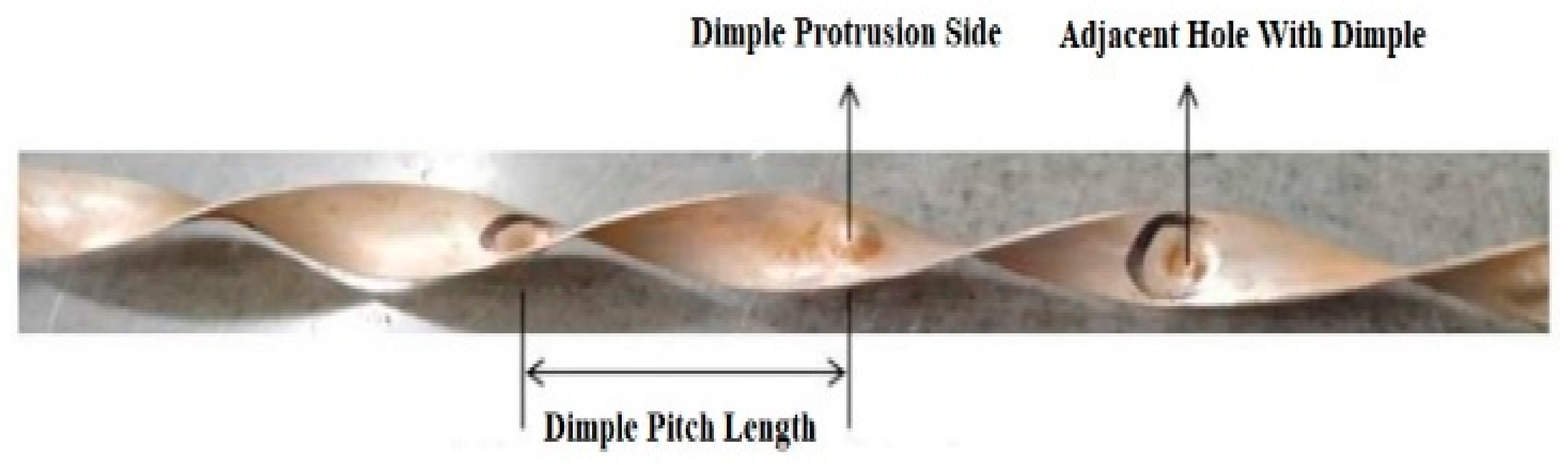
  • Providing a dimple protrusion surface only on front face with a hole configuration placed adjacent to it over the tube length of 1500 mm.

2. Methodology

The twisted tape insert in the double-pipe heat exchanger experimental setup is fabricated with aluminum with a dimple configuration. Among all the commonly used plain tube inserts, twisted tape insert is considered as the primary choice and is therefore extensively studied by numerous authors worldwide. Mainly two types of twisted tape inserts are used in the experiment: plain and dimpled configurations. Plain twisted tape was made from an aluminum sheet of thickness 1 mm, width 15 mm and length 1500 mm. Initially the aluminum strip was fixed in two jaws of vices and distance between the vices was more than 1500 mm. One of the jaws was fixed whereas the other was free and both were mounted on a lead screw. One of the jaws which was free to rotate was rotated twenty-four times in order to obtain a twisted tape of twist ratio 5.5.

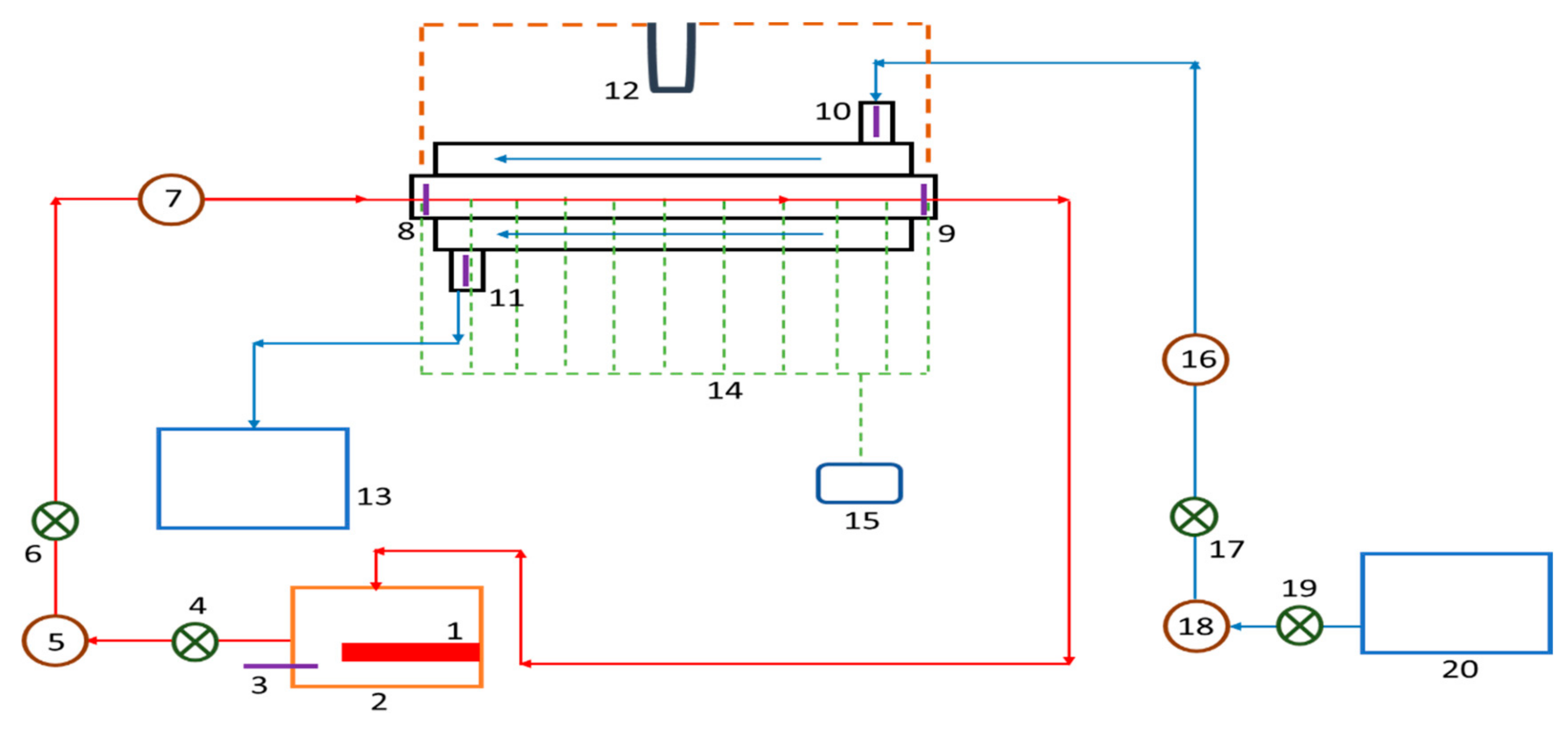
3. Experimental Set-Up

The double-pipe heat exchanger flow circuit is represented in Figure 1. The experimental setup with the above configuration was constructed, with water as a working fluid pumped using a centrifugal pump inserted with a valve and rotameter. To ensure that the flow was fully developed at the entrance of the test section and was calm at exit of test section, additional tubes of the same material were added at the entrance and exit of the test section for turbulent flow. To minimize the heat loss from developing- and calming- sections, both the sections were properly insulated with glass wool.
A double-pipe heat exchanger (DPHE) with liquid as water for working as the experimental setup. The internal tube contained hot water, while the outer contained cold water. The hot-water route was made up of a water temperature propane tank including an electric heater and rheostat, 0.5 HP capillary tube, a rotameter, and tubing along the controls. The steam lines and the propane tank were adequately covered with insulation. 0.5 HP capillary tube, a rotameter, and a tubing including controls, made up the cold-water route. The internal tube had a 2 mm diameter (D), an average diameter (D) of 16 mm, and a duration of 2.4 m, however exterior piping had a depth of 3 mm, an average (D) of 30 mm, and a length of 2.4 m. Hot water circulate temperatures were maintained at 70 °C, while fluid intake temperatures were maintained at ambient temperature (30–32 °C). To measure the surface temperature, six T-type regulated heat exchangers with such an imprecision were positioned at 0.1 °C and placed over the tube’s top of the pipe. Apart from resulting in an imprecision error of 0.1 °C, the input and output temperatures of the freeze and warm water were listed with the heat transfer rate. A u-tube manometer was used to measure the stress drop of hot water flowing in the estimate point. Once the system reached a stable state, the value of heat flux, flow rate, and frequency were noted for increased performance. In all circumstances, the twisted tapes utilized in the study were constructed of aluminum with a depth of 1 mm and a twist ratio of 5.5. On the basis of heat flux, overall temperature of tube, and flow rates, the efficiency of the recommended twisted tape inserts with the dimple configuration in obtaining an accelerated rate of heat transfer was investigated. Twisted tape inserts with dimple configurations for obtaining an accelerated rate of heat transfer were studied. At a constant twist ratio of 5.5, variations in characteristic of twisted tape with dimple configurations of various diameters (D) of 2-, 4-, and 6-mm with D/H ratios of 1.5, 3.0, and 4.5, were made. The heated fluid movement through into the inner tube was adjusted in Reynolds number from 6000 to 14,000. The ‘Re’ range was chosen based on median inflow stream frequency and tube diameter (Hd). The employed twisted tapes fabrication diagram is depicted in below Figure 2.

4. Data Analysis [54]

It is important to comprehend basic geometry and performance evaluation-related characteristics.
  • Twisted factor is spatial measurement amidst successive points of a geometrical configuration on co-planes measured parallel to twisted tape axis (i.e., 50% of the twisted ratio) divided by Total Hydraulic (Td). ‘TR’ or ‘y’ are typical abbreviations used for it.
T R = H D
2.
Reynolds Number (Re) is the ratio of the fluid’s dynamic viscosity to compound of the tube’s (Hd), median fluid flow rate, and volume. Re is symbol used for it.
Re = d e u ρ u
3.
Nusselt Number—It is a proportionality between product of convective heat transfer rate factor and tube diameter (Hd) to electrical properties.
N u = h i D K h
4.
Friction factor is proportionality between the product of tube’s total pressure decrease and corresponding Inner Tube Diameter equals the square of the average fluid velocity in the tube multiplied by density, characteristic linear dimension, and inner tube diameter. It is shown in use by ‘f’.
f = 2 Δ d e ρ μ 2 L
5.
Thermal enhancement efficiency is to measure performance evaluation criteria (PEC) or Thermal figure of merit factor or Overall efficiency η when pumping power is constant. It is defined as the ratio of Nu ratio N u T / N u 0 [Ratio of N u T to N u 0 ] to that of cubic root of friction factors ratio f T / f 0 1 3 [Ratio of friction factor with twisted tape insert (fT) to that of friction factor without twisted tape or plane tube (f0)] and calibrated using mathematical correlation: Thermal figure of merit factor or Overall efficiency η or of performance evaluation criteria It fortifies stability of ‘Nu’ and (f) and also core emphasis will be put forth on modification of twisted tape(s) shapes.
P E C = N u T N u o f T f o 0.33
As an effect of this, it promotes for the material optimization used for heat exchanger system design studies.
In above correlations, (H) = half-length Twist Pitch, (D) = Total Hydraulic Tube Diameter, (de) = Inner Tube Diameter, (u) = average fluid velocity, (ρ) = fluid density, (µ) = dynamic viscosity of fluid, (k) = thermal conductivity, (h) = convective heat transfer coefficient., (ΔP) = Pressure Drop, and (LC) = Characteristic Linear Length. The majority mean temperature for warm and chilled water is considered to be the average value of in and out temperature equation represents a number of formulae used in the current work.
The average heat water,
T h = T h i + T h 0 2
The average temperature of cold water,
T c = T c i + T c 0 2
Mean temperature of wall
T w = T 1 + T 2 + T 3 + T 4 + T 5 + T 6 6
Mean velocity of warm water,
U h = V h × ρ i n π D 2 ρ h 4
Reynolds number,
R e = U h × D I V
The rate of heat transmission released by Hot water,
Q h = ρ h × V h × C p T h i T h 0
Cold water absorbs heat at a high rate.,
Q c = ρ c × V c × C p c T c o T c i
Heat transfer rate of the thermal gradient rate system is defined as the mean value.
Q = Q h + Q c 2 = h i × A s × T h T w
Nusselt number
N u = h i D K h
Friction factor
f = 2 Δ P 4 ρ h L V h 2
Validation of plain tube experimental results of ‘Nu’ and ‘f’ with Gnielinski and Filonenko correlations, respectively.
Gnielinski Correlation
N u f = f 8 Re 1000 p r f 1 + 12.7 f 8 1 2 Pr 0.66 1 1 + d L 2 3 C 1
Filonenko Correlation
F c = 1.82 ln 12884 1.64 2
Data collected from the experimental work for a plain tube is processed according to the selective eight Reynolds numbers within the specified range 6000 < Re < 14,000 and Gnielinski and Filonenko correlations.

5. Results and Discussions

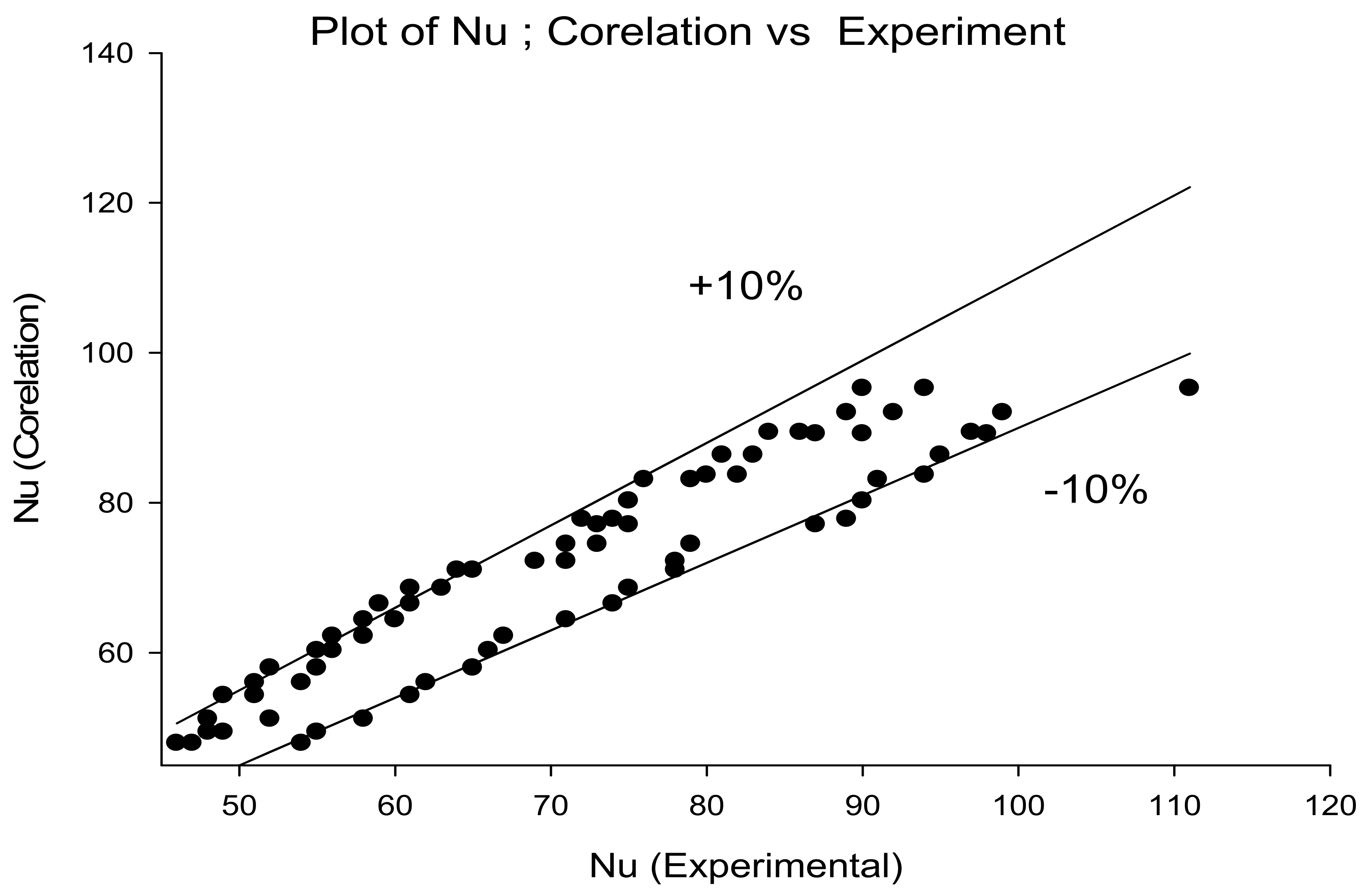
5.1. Validation of Experimental Setup

Data collected from the experimental work for twisted tape configuration was processed according to the relations mentioned in all specific eight Reynolds number conditions.
The experimental setup was authenticated along with standard correlations recommended by different researchers to verify for the correctness of data obtained through experiments. Estimates of ‘Nu’ and ‘f’ derived from the studies carried on plain twisted tape without inserts were matched through Gnielinski and Filonenko correlations, respectively. The conclusions revealed that investigational values were inside tolerable limits thus acceptable for the experimental setup. The determined deviance found was ±7% for ‘Nu’ and ±7.5% for ‘f’, providing a dimple protrusion surface only on the front face with a hole configuration placed adjacent to it over the tube length of 1500 mm.
Correlations designed for ‘f’ and ‘Nu’ for a kind as working and geometrical factors to be investigated, Figure 3, Figure 4, Figure 5, Figure 6, Figure 7, Figure 8, Figure 9, Figure 10, Figure 11 and Figure 12 were developed using the data acquired since investigational, for ‘Nu’ and ‘f’. Nusselt number and friction factor are stable parameters of mutually working and movement causing limitations, of Reynolds number, dimple diameter to depth ratio (D/H) ratio, and Dimple diameter (D), according to results of experimental investigation. The mathematical correlation between these ‘Nu’ and ‘f’ properties, as well as system and operating factors, is as follows:
N u = f R e D H , D
f = f R e D H , D
A range of Reynolds number was plotted against all the investigational values collected for ‘Nu’ with dimple geometry, indicating that a direct correlation among ‘Nu’ and ‘Re’ would almost occur. For the data presented, a regression analysis was performed, and bend fitting was used to calculate mean line of all slopes.
N u = A o Re 0.7818
In this equation, the coefficient Ao is unquestionably a meaning in relation to other inducing fundamentals, is to procedure dimple diameter to depth ratio (D/H) as a deterioration examination parameter and draw a graph among ln(Ao) and (D/H) shown in Figure 3. This correlation was discovered using a second order deterioration investigation and optimal curve for the full summary.
ln N u Re 0.7817 = ln B 0 + A 11 ln D H + A 12 ln D H 2
This above equation can be rewritten as and shown Figure 4.
N u Re 0.7817 = B 0 D H 0.3738 E x p 0.1581 ln D H 2
Similarly,
ln N u Re 0.7817 D H 0.3738 E x p 0.1581 ln D H 2
which is ln(B0) with the dimple Natural log scale diameter ln Diameter was visually shown in Figure 5, and the regression produced this equation as
Similarly,
ln N u Re 0.7817 D H 0.3738 E x p 0.1581 ln D H 2
which is ln(B0) with the dimple Natural log scale diameter ln(D) was visually shown in Figure 6, and the regression produced this equation as
ln N u Re 0.7817 D H 0.3738 E x p 0.1581 ln D H 2 = C 0 D 3.597 E x p 1.177 ln D 2
The value of the last constant, C0, may be used to write the final correlation
N u = 0.00314 × Re 0.7817 D H 0.3738 E x p 0.1581 ln D H 2 D 3.597 E x p 1.177 ln D 2
From the experimentally collected data, investigation was used to create geometric correlations for ‘f’. friction factor and Reynolds number established was first, graphically shown in Figure 7, on the numeric values of ln (friction factor) and ln (Reynolds number) for each data point. Linear deterioration investigation was carried out, and the arch correct was carried out in such a way that a conventional stripe passing finished these arguments was generated, which is communicated as:
f = A 0 Re 0.5508
The coefficient Ao is greatly influenced by other geometrical factors. Now, using factor (D/H), rate of f Re 0.1521 = A 0 is graphically shown in Figure 8, on a log-log scale as a purpose of (D/H).
ln f Re 0.5508 = ln B 0 + A 11 ln D H + A 12 ln D H 2
As follow above equation.
f Re 0.5508 = B 0 D H 0.4764 E x p 0.0698 ln D H 2
Similarly,
ln f Re 0.5508 D H 0.4764 E x p 0.0698 ln D H 2
which is ln(B0) with the Diameter (D) ln(D) remained distinctly designed arranged usual graph shown in Figure 9, measurement and deterioration created this calculation.
ln f Re 0.5508 D H 0.4764 E x p 0.0698 ln D H 2 = C 0 D 0.7095 E x p 0.3197 ln D 2
By using the value of the final constant, C0, the final correlation can be expressed and shown in Figure 10.
f = 63.07 × Re 0.7817 Re 0.5508 D H 0.4764 E x p 0.0698 ln D H 2 D 0.7095 E x p 0.3197 ln D 2

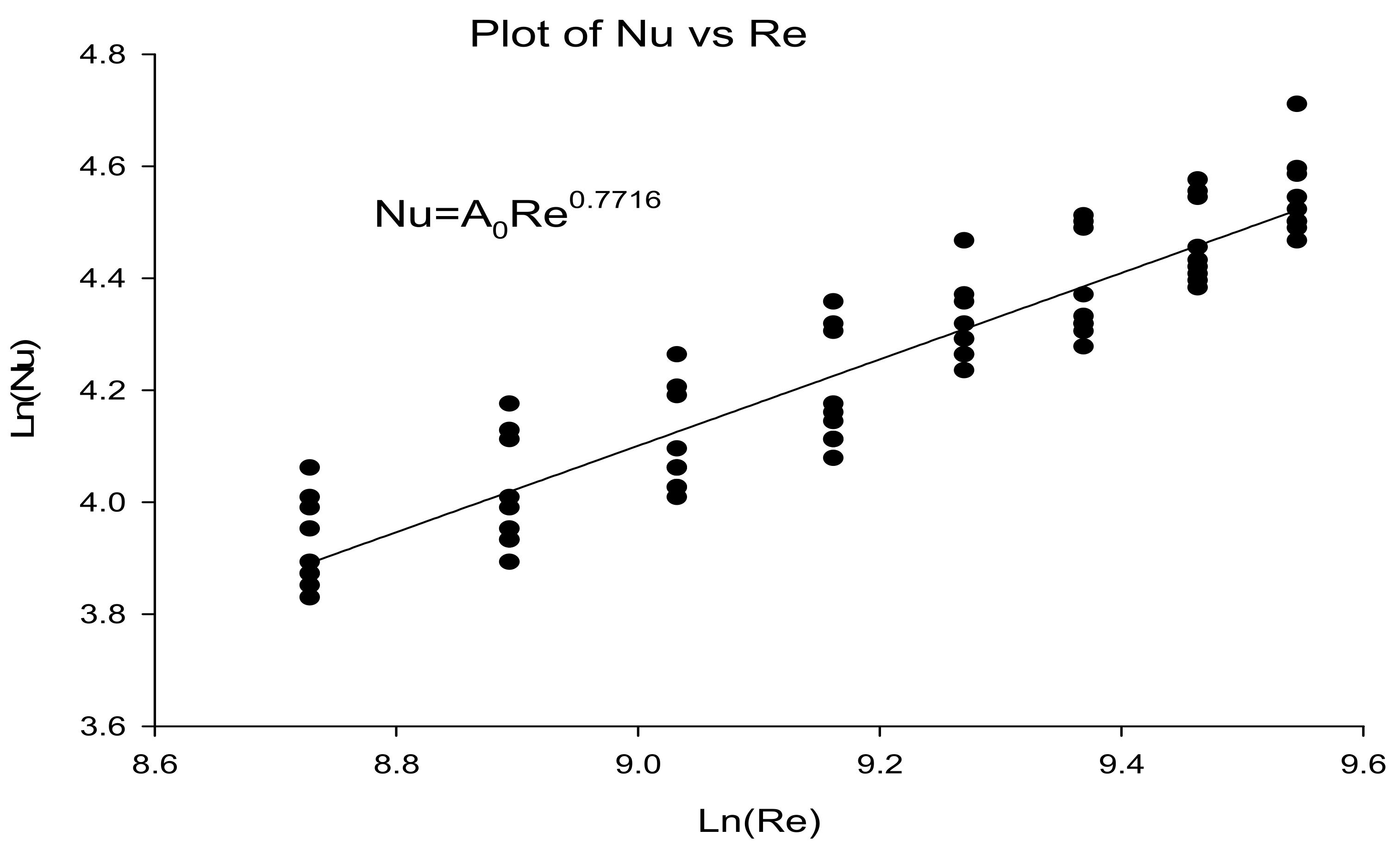
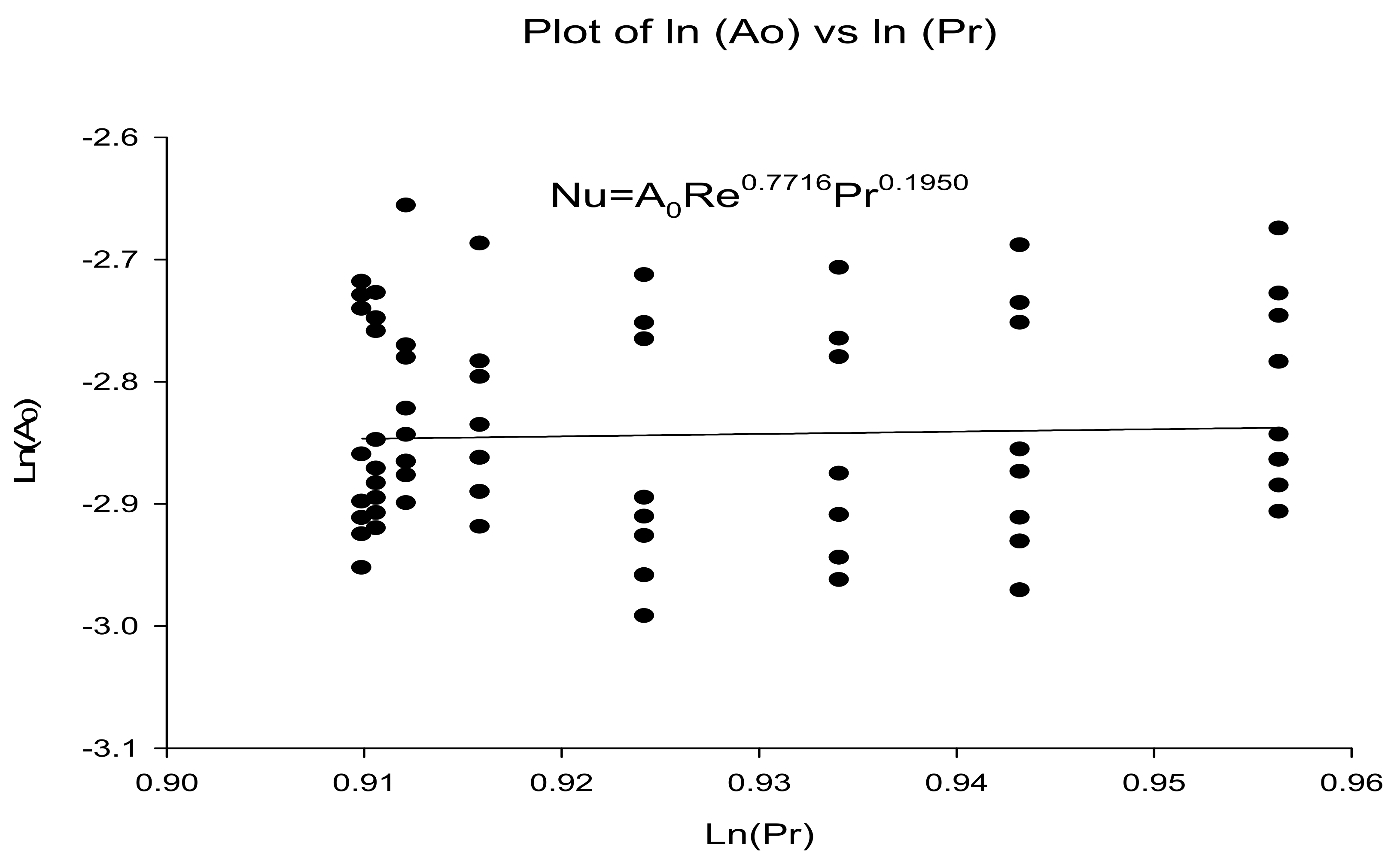
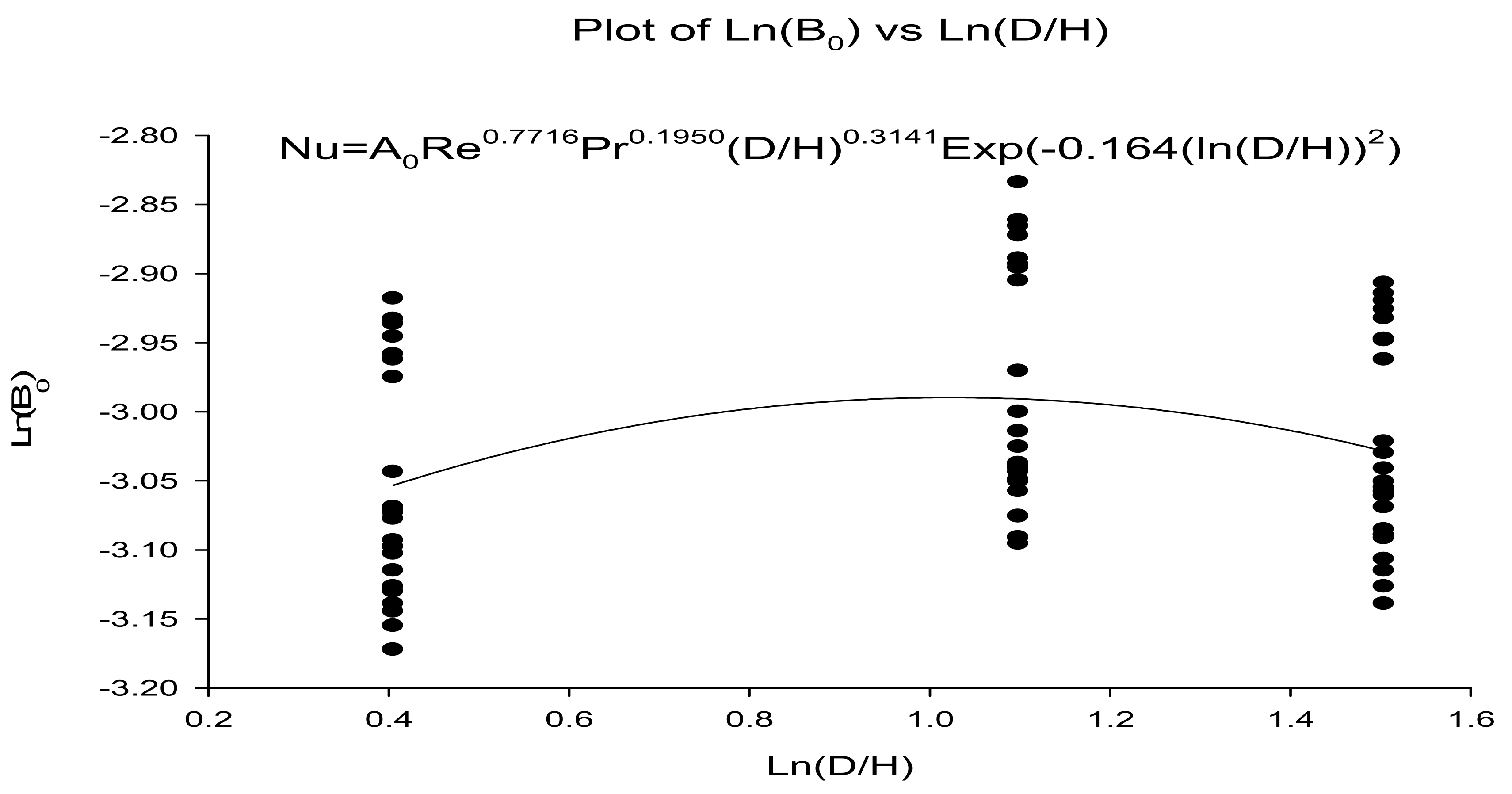
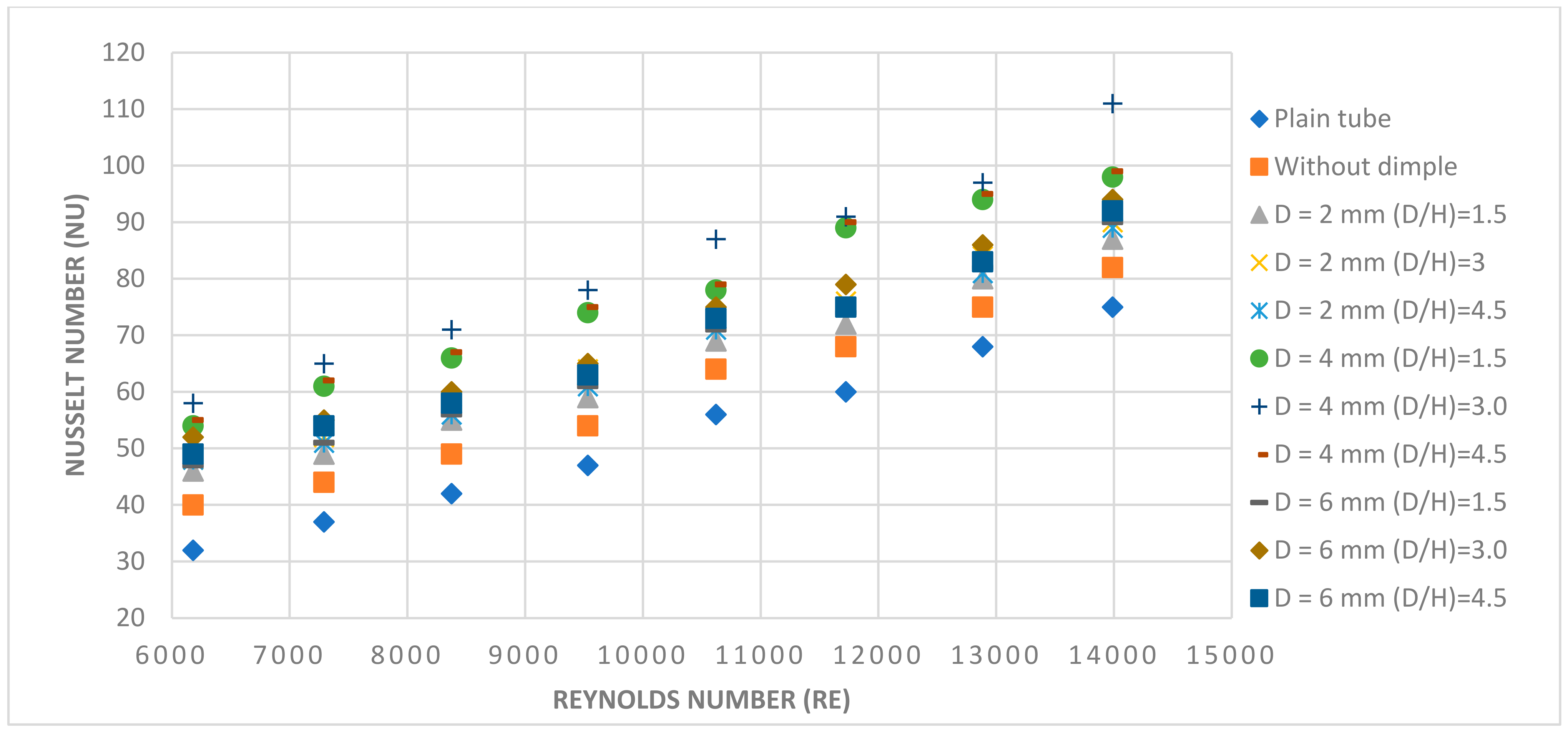
5.1.1. Impact of Dimple Diameter (D) and Dimple Diameter to Depth Ratio (D/H) on Heat Transfer

The deviation of Nusselt number with Reynolds number of plain tube, twisted tape without dimples and twisted tape with dimples (D = 2, 4 and 6 mm with D/H = 1.5, 3 and 4.5) are given provided in Figure 11. As is evident from all these cases, there is a substantial rise in the numeric value of Nu as Re increases. when compared to a tube without insert, a twisted insert without dimples and with dimples actually increases the rate of heat transfer. The value of Nu increases for dimple diameter 2–4 mm, whereas it decreases for dimple diameter 4–6 mm over the range of Reynolds numbers studied.

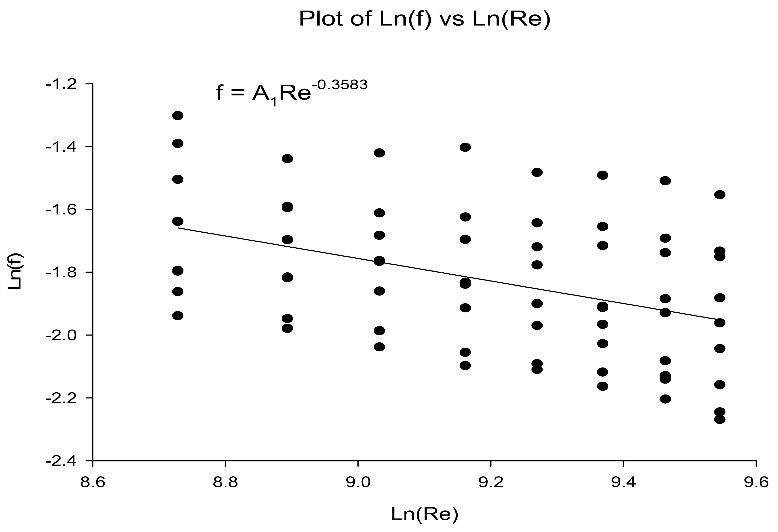
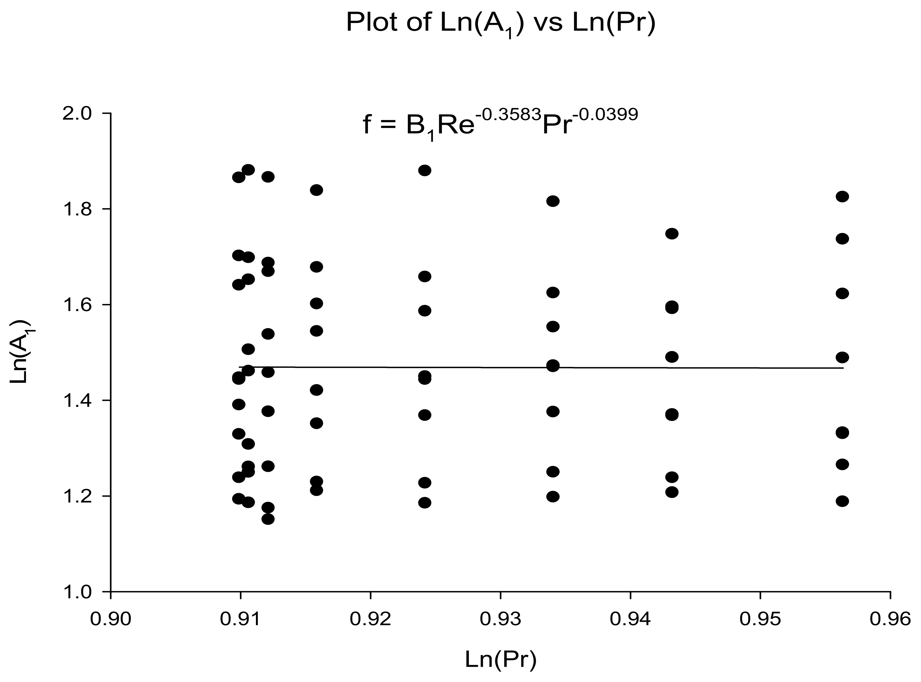
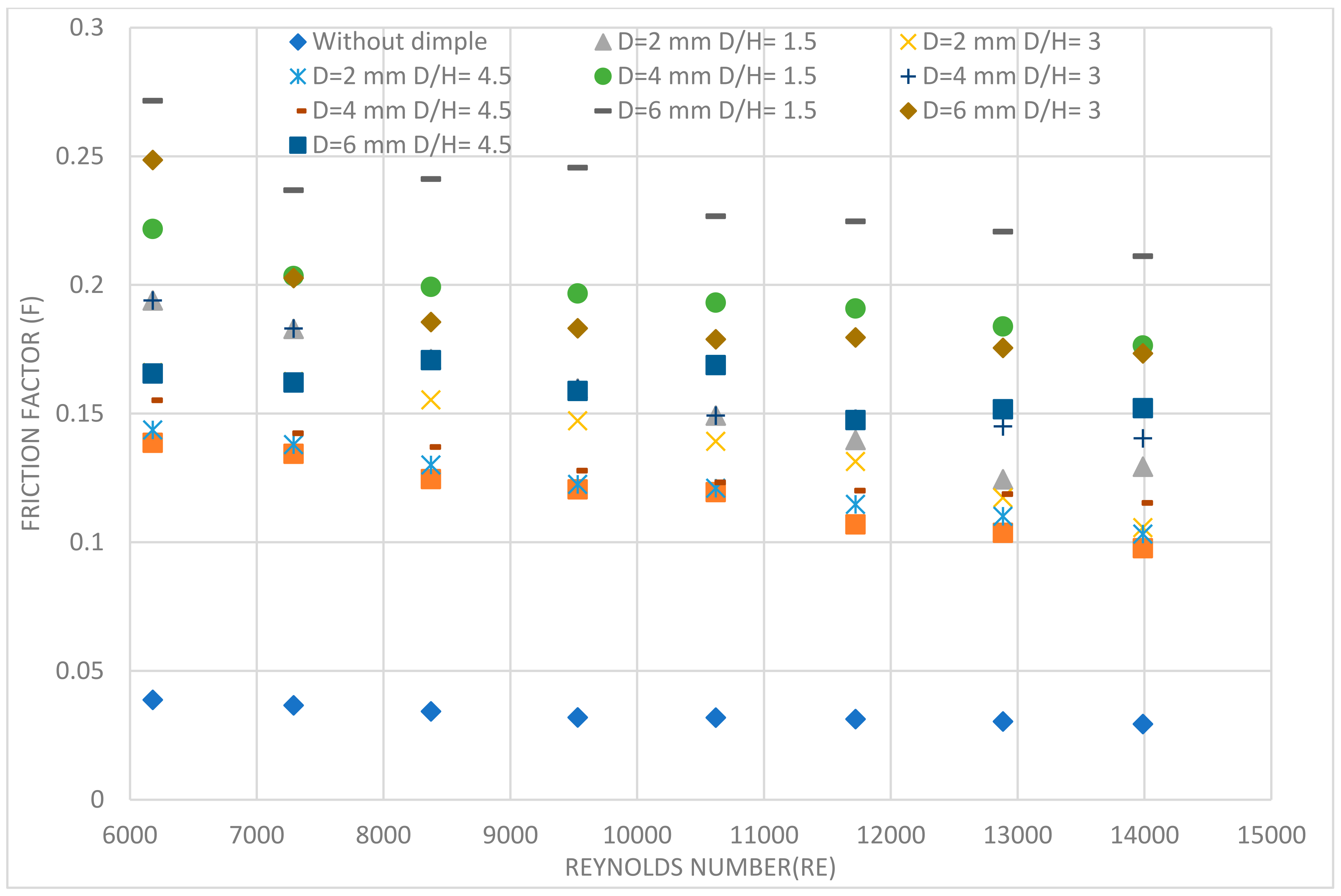
5.1.2. Effect of Dimple Diameter and Dimple Diameter (D) to Depth Ratio (D/H) on Friction Factor

The variation of friction factor with Reynolds number for tubes without insert, twisted tape without dimples and twisted tape with dimples of diameters, 2, 4, and 6 mm (with (D/H) ratios = 1.5, 3 and 4.5 for each diameter respectively) are given in Figure 12. It can be seen that in all cases, ‘f’ decreasing upon increasing ‘Re’ and twisted tapes yielded higher ‘f’ value than the tube without an insert. The friction factor is directly proportional to the depth of dimple. In both cases, the numeric value of ‘f’ decreases between (D/H) = 1.5 and (D/H) = 3, as well as between (D/H) = 3 and (D/H) = 4.5, with (D/H) = 4.5 having the lowest value of ‘f’. In accumulation to this, ‘f’ reductions from dimple diameter 6 mm to 4 mm with tiniest value for Diameter = 2 mm. It is because an increase in dimple depth decreases the flow area and provides more surface contact resistance leading to enhancement in friction factor.

6. Conclusions

In a range of Reynolds numbers, twisted tape inserts with dimple configurations, plain tube and twisted tape inserts without dimples with higher ‘Nu’ and ‘f’ were studied. Results showed that as the dimple diameter (D) of the dimple expands from 2 to 4 mm, the Nusselt number rises, then falls as the diameter goes from 4 to 6 mm. This is because the swirl flow is trapped at the bottom of the depression, and the protrusion separates the flow. The diameter of the dimple determines the friction factor, which is proportionate to dimple dimeter (D) of the dimple configuration. The dimple configuration of twisted tape reduces the flow area while increasing the contact surface. When compared to ‘Nu’, the influence of the twisted tape with a dimple configuration on ‘f’ becomes more important as the Reynolds number (Re) rises. Performance evaluation criteria (PEC) of the twisted tape without dimples was the lowest among all other arrangements over the range of ‘Re’ examined, implying that the friction factor takes primacy over the Nusselt number in this circumstance.
i.
According to the conclusions derived from this research, twisted tape inserts with dimple configurations significantly increased the values of the Nusselt number (Nu) and Reynolds number (Re) after a certain limit of Reynolds number (Re) in the experiments evaluated;
ii.
Correlations were developed for Nusselt number and friction factor and these correlations may be helpful for further applications;
iii.
This analysis makes it possible to investigate many different aspects in double-pipe heat exchangers with twisted tape inserts, and the following areas of research are suggested for future research:
  • Experimental study of ‘Nu’ and ‘f’ in DPHE using dimpled configuration twisted tape with selected Nano fluid.
  • Experimental study of heat transfer and friction factor in double pipe heat exchanger using conical dimpled configuration twisted tape.
  • Analysis of Nusselt number and friction factor(f) in DPHE using dimpled configuration twisted strip with diverse twist ratio.
  • Experimental study of ‘Nu’ and ‘f’ in DPHE using dimpled twisted tape of different length and at different locations.

Author Contributions

Conceptualization, J.H.; methodology, R.K.; validation, P.K.C.; writing—original draft preparation, N.K.G.; writing—review & editing, D.D. All authors have read and agreed to the published version of the manuscript.

Funding

This research received no external funding.

Institutional Review Board Statement

Not applicable.

Informed Consent Statement

Not applicable.

Data Availability Statement

Not applicable.

Conflicts of Interest

The authors declare no conflict of interest.

Nomenclature

AcronymDescriptionUnit
CPSpecific heat at constant pressureJ/kg K
CVSpecific heat at constant volumeJ/kg K
eInternal energyJ/kg
E0Total energyJ/kg
hEnthalpyJ/kg
kTurbulent kinetic energyJ/kg = m2/s2
pStatic pressurePa
RSpecific gas constantJ/kg K
tTimeS
TStatic temperatureK
U*Friction velocitym/s
uiVelocitym/s
εTurbulence dissipationJ/kgs
μ Dynamic viscosityN s/m2
VKinematic viscosityM2/s
ρDensityKg/m3
ωSpecific dissipations−1
Dimensionless parameters
ParameterDescriptionDescription
NuNusselt numberhL/k
PrPrandtl numberuCp/k
ReReynolds numberρV L/μ
Subscript
tTurbulent property
0Stagnation/total property
Superscript
convConvective part
diffDiffusive part
lamLaminar part

References

  1. Sneha, K.N.; Mahabaleshwar, U.S.; Sharifpur, M.; Ahmadi, M.H.; Al-Bahrani, M. Entropy Analysis in MHD CNTS Flow Due to a Stretching Surface with Thermal Radiation and Heat Source/Sink. Mathematics 2022, 10, 3404. [Google Scholar] [CrossRef]
  2. Sadeghi, K.; Kahani, M.; Ahmadi, M.H.; Zamen, M. CFD Modelling and Visual Analysis of Heat Transfer and Flow Pattern in a Vertical Two-Phase Closed Thermosyphon for Moderate-Temperature Application. Energies 2022, 15, 8955. [Google Scholar] [CrossRef]
  3. Zandie, M.; Moghaddas, A.; Kazemi, A.; Ahmadi, M.; Feshkache, H.N.; Sharifpur, M. The impact of employing a magnetic field as well as Fe3O4 nanoparticles on the performance of phase change materials. Eng. Appl. Comput. Fluid Mech. 2022, 16, 196–214. [Google Scholar] [CrossRef]
  4. Qian, X.; Lee, S.; Yang, Y. Heat Transfer Coefficient Estimation and Performance Evaluation of Shell and Tube Heat Exchanger Using Flue Gas. Processes 2021, 9, 939. [Google Scholar] [CrossRef]
  5. Enayatizade, H.; Arjomand, A.; Ahmadi, M.H. Design and multi-scenario optimization of a hybrid power system based on a working gas turbine: Energy, Exergy, Exergoeconomic and Environmental evaluation. Energy Rep. 2022, 8, 12916–12943. [Google Scholar] [CrossRef]
  6. Omidi, M.; Farhadi, M.; Jafari, M. A comprehensive review on double pipe heat exchangers. Appl. Therm. Eng. 2017, 110, 1075–1090. [Google Scholar] [CrossRef]
  7. Zhang, X.; Liu, Z.; Liu, W. Numerical studies on heat transfer and flow characteristics for laminar flow in a tube with multiple regularly spaced twisted tapes. Int. J. Therm. Sci. 2012, 58, 157–167. [Google Scholar] [CrossRef]
  8. Zhang, Z.; Yang, W.; Guan, C.; Ding, Y.; Li, F.; Yan, H. Heat transfer and friction characteristics of turbulent flow through plain tube inserted with rotor-assembled strands. Exp. Therm. Fluid Sci. 2012, 38, 33–39. [Google Scholar] [CrossRef]
  9. Saha, S.; Saha, S.K. Enhancement of heat transfer of laminar flow of viscous oil through a circular tube having integral helical rib roughness and fitted with helical screw-tapes. Exp. Therm. Fluid Sci. 2013, 47, 81–89. [Google Scholar] [CrossRef]
  10. Zhang, C.; Wang, D.; Ren, K.; Han, Y.; Zhu, Y.; Peng, X.; Deng, J.; Zhang, X. A comparative review of self-rotating and stationary twisted tape inserts in heat exchanger. Renew. Sust. Energ. Rev. 2016, 53, 433–449. [Google Scholar] [CrossRef]
  11. Rostami, S.; Ahmadi, N.; Khorasani, S. Experimental investigations of thermo-exergitic behavior of a four-start helically corrugated heat exchanger with air/water two-phase flow. Int. J. Therm. Sci. 2019, 145, 106030. [Google Scholar] [CrossRef]
  12. Zapata, B.L.; Escobar, R.; Medina, M.A.; Zaragoza, C.M.A. State Variables Estimation for a Counter-Flow Double-Pipe Heat Exchanger Using Multi-linear Model. In Proceedings of the IEEE Electronics, Robotics and Automotive Mechanics Conference, Cuernavaca, Brazil, 22–25 September 2009; pp. 22–25. [Google Scholar]
  13. Qian, X.; Yang, Y.; Lee, S.W. Design and Evaluation of the Lab-Scale Shell and Tube Heat Exchanger (STHE) for Poultry Litter to Energy Production. Processes 2020, 8, 500. [Google Scholar] [CrossRef]
  14. Abdelghani-Idrissi, M.; Bagui, F.; Estel, L. Analytical and experimental response time to flow rate step along a counter flow double pipe heat exchanger. Int. J. Heat Mass Transf. 2001, 44, 3721–3730. [Google Scholar] [CrossRef]
  15. Yang, L.; Du, K. A comprehensive review on heat transfer characteristics of TiO2 nanofluids. Int. J. Heat Mass Transf. 2017, 108, 11–31. [Google Scholar] [CrossRef]
  16. Sundar, L.S.; Otero-Irurueta, G.; Singh, M.K.; Sousa, A.C. Heat transfer and friction factor of multi-walled carbon nanotubes—Fe3O4 nanocomposite nanofluids flow in a tube with/without longitudinal strip inserts. Int. J. Heat Mass Transf. 2016, 100, 691–703. [Google Scholar] [CrossRef]
  17. Theresa, O.F.O.E.G.B.U. Gender and Acquisition of Agricultural Science Skills in Secondary Schools: Video Taped Instructional Approach. Int. J. Res. Humanit. Arts Lit. 2015, 3, 2321–8878. [Google Scholar]
  18. Sheikholeslami, M.; Gorji-Bandpy, M.; Ganji, D.D. Fluid flow and heat transfer in an air-to-water double-pipe heat exchanger. Eur. Phys. J. Plus 2015, 130, 225. [Google Scholar] [CrossRef]
  19. Dezfoli, A.R.A.; Mehrabian, M.A. The Overall Heat Transfer Characteristics of a Double-Pipe Heat Exchanger. Heat Transf. Res. 2009, 40, 555–570. [Google Scholar] [CrossRef]
  20. Iqbal, Z.; Syed, K.; Ishaq, M. Fin design for conjugate heat transfer optimization in double pipe. Int. J. Therm. Sci. 2015, 94, 242–258. [Google Scholar] [CrossRef]
  21. Wongcharee, K.; Eiamsa-Ard, S. Heat transfer enhancement by twisted tapes with alternate-axes and triangular, rectangular and trapezoidal wings. Chem. Eng. Process. Process Intensif. 2011, 50, 211–219. [Google Scholar] [CrossRef]
  22. Iqbal, Z.; Syed, K.; Ishaq, M. Optimal fin shape in finned double pipe with fully developed laminar flow. Appl. Therm. Eng. 2013, 51, 1202–1223. [Google Scholar] [CrossRef]
  23. Ebrahimi, A.; Ghorbani, B.; Delpisheh, M.; Ahmadi, M.H. A comprehensive evaluation of a novel integrated system consisting of hydrogen boil-off gas reliquifying process and polymer exchange membrane fuel cell using exergoeconomic and Markov analyses. Energy Rep. 2022, 8, 1283–1297. [Google Scholar] [CrossRef]
  24. Ghodbane, M.; Said, Z.; Ketfi, O.; Boumeddane, B.; Hoang, A.T.; Sheikholeslami, M.; Assad, M.E.H.; Ahmadi, M.H.; Nguyen, V.N.; Tran, V.D.; et al. Thermal performance assessment of an ejector air-conditioning system with parabolic trough collector using R718 as a refrigerant: A case study in Algerian desert region. Sustain. Energy Technol. Assess. 2022, 53, 102513. [Google Scholar] [CrossRef]
  25. Sharifpur, M.; Ahmadi, M.H.; Rungamornrat, J.; Mohsen, F.M. Thermal Management of Solar Photovoltaic Cell by Using Single Walled Carbon Nanotube (SWCNT)/Water: Numerical Simulation and Sensitivity Analysis. Sustainability 2022, 14, 11523. [Google Scholar] [CrossRef]
  26. Sabbagh, O.; Fanaei, M.A.; Arjomand, A.; Ahmadi, M.H. Plantwide control and dynamic assessment of a novel NGL/LNG integrated scheme. Sustain. Energy Technol. Assess. 2022, 52, 102226. [Google Scholar] [CrossRef]
  27. Dhivagar, R.; Shoeibi, S.; Kargarsharifabad, H.; Ahmadi, M.H.; Sharifpur, M. Performance enhancement of a solar still using magnetic powder as an energy storage medium-exergy and environmental analysis. Energy Sci. Eng. 2022, 10, 3154–3166. [Google Scholar] [CrossRef]
  28. Memari, M.; Boumari, E.; Shoghi, A.; Maddah, H.; Ahmadi, M.H.; Sharifpur, M. Numerical investigation of heat transfer in a tube equipped with twisted tape with different angles and under constant heat flux with copper nanofluid and evaluation of the results obtained using perceptron artificial neural networks. Numer. Heat Transf. Part A Appl. 2022, 82, 169–192. [Google Scholar] [CrossRef]
  29. Salek, F.; Babaie, M.; Naserian, M.M.; Ahmadi, M.H. Power enhancement of a turbo-charged industrial diesel engine by using of a waste heat recovery system based on inverted Brayton and organic Rankine cycles. Fuel 2022, 322, 124036. [Google Scholar] [CrossRef]
  30. Ming, T.; Liao, X.; Shi, T.; Yin, K.; Wang, Z.; Ahmadi, M.H.; Wu, Y. The thermal analysis of the heat dissipation system of the charging module integrated with ultra-thin heat pipes. Energy Built Environ. 2022. [Google Scholar] [CrossRef]
  31. Menni, Y.; Ghazvini, M.; Ameur, H.; Kim, M.; Ahmadi, M.H.; Sharifpur, M. Combination of baffling technique and high-thermal conductivity fluids to enhance the overall performances of solar channels. Eng. Comput. 2020, 38, 607–628. [Google Scholar] [CrossRef]
  32. Abdoos, B.; Ghazvini, M.; Pourfayaz, F.; Ahmadi, M.H.; Nouralishahi, A. A comprehensive review of nano-phase change materials with a focus on the effects of influential factors. Environ. Prog. Sustain. Energy 2022, 41, e13808. [Google Scholar] [CrossRef]
  33. Nikzad, M.; Zamen, M.; Ahmadi, M.H. Theoretical and experimental investigation of a photovoltaic/thermal panel partially equipped with thermoelectric generator under unstable operating conditions. Int. J. Energy Res. 2022, 46, 6790–6805. [Google Scholar] [CrossRef]
  34. Mahdavi, M.; Sharifpur, M.; Aybar, H.S.; Ahmadi, M.H.; Chamkha, A.J.; Alotaibi, M.F.; Meyer, J.P. Thermal boundary condition analysis of cooling objects exposed to a free impinging jet using the heatline concept. Eng. Appl. Comput. Fluid Mech. 2021, 15, 1919–1931. [Google Scholar] [CrossRef]
  35. Rafiei, A.; Loni, R.; Mahadzir, S.B.; Najafi, G.; Sadeghzadeh, M.; Mazlan, M.; Ahmadi, M.H. Hybrid solar desalination system for generation electricity and freshwater with nanofluid application: Energy, exergy, and environmental aspects. Sustain. Energy Technol. Assess. 2022, 50, 101716. [Google Scholar] [CrossRef]
  36. Alayi, R.; Mohkam, M.; Seyednouri, S.R.; Ahmadi, M.H.; Sharifpur, M. Energy/Economic Analysis and Optimization of On-Grid Photovoltaic System Using CPSO Algorithm. Sustainability 2021, 13, 12420. [Google Scholar] [CrossRef]
  37. Kalantar, S.V.; Saifoddin, A.A.; Hajinezhad, A.; Ahmadi, M.H. A Solution to Prevent a Blackout Crisis: Determining the Behavioral Potential and Capacity of Solar Power. Int. J. Photoenergy 2021, 2021, 2092842. [Google Scholar] [CrossRef]
  38. Ghorbani, B.; Rahnavard, Z.; Ahmadi, M.H.; Jouybari, A.K. An innovative hybrid structure of solar PV-driven air separation unit, molten carbonate fuel cell, and absorption–compression refrigeration system (Process development and exergy analysis). Energy Rep. 2021, 7, 8960–8972. [Google Scholar] [CrossRef]
  39. Jalili, M.; Ghasempour, R.; Ahmadi, M.H.; Chitsaz, A.; Holagh, S.G. An integrated CCHP system based on biomass and natural gas co-firing: Exergetic and thermo-economic assessments in the framework of energy nexus. Energy Nexus 2021, 5, 100016. [Google Scholar] [CrossRef]
  40. Sadeghzadeh, M.; Ghorbani, B.; Ahmadi, M.H.; Sharma, S. A solar-driven plant to produce power, cooling, freshwater, and hot water for an industrial complex. Energy Rep. 2021, 7, 5344–5358. [Google Scholar] [CrossRef]
  41. Singh, G.; Sharma, S.; Singh, J.; Kumar, S.; Singh, Y.; Ahmadi, M.H.; Issakhov, A. Optimization of performance, combustion and emission characteristics of acetylene aspirated diesel engine with oxygenated fuels: An Experimental approach. Energy Rep. 2021, 7, 1857–1874. [Google Scholar] [CrossRef]
  42. Akpinar, E.K. Evaluation of heat transfer and exergy loss in a concentric double pipe exchanger equipped with helical wires. Energy Convers. Manag. 2006, 47, 3473–3486. [Google Scholar] [CrossRef]
  43. Mozley, J.M. Predicting Dynamics of Concentric Pipe Heat Exchangers. Ind. Eng. Chem. 1956, 48, 1035–1041. [Google Scholar] [CrossRef]
  44. Cohen, W.C.; Johnson, E.F. Dynamic Characteristics of Double-Pipe Heat Exchangers. Ind. Eng. Chem. 1956, 48, 1031–1034. [Google Scholar] [CrossRef]
  45. Song, S.; Liao, Q.; Shen, W. Laminar heat transfer and friction characteristics of microencapsulated phase change material slurry in a circular tube with twisted tape inserts. Appl. Therm. Eng. 2013, 50, 791–798. [Google Scholar] [CrossRef]
  46. Lachi, M.; El Wakil, N.; Padet, J. The time constant of double pipe and one pass shell-and-tube heat exchangers in the case of varying fluid flow rates. Int. J. Heat Mass Transf. 1997, 40, 2067–2079. [Google Scholar] [CrossRef]
  47. Yadav, A.S. Effect of half-length twisted-tape turbulators on heat transfer and pressure drop characteristics inside a double pipe u-bend heat exchanger. JJMIE 2009, 3, 17–22. [Google Scholar]
  48. Aicher, T.; Kim, W. Experimental investigation of the influence of the cross flow in the nozzle region on the shell-side heat transfer in double-pipe heat exchangers. Int. Commun. Heat Mass Transf. 1998, 25, 43–58. [Google Scholar] [CrossRef]
  49. Iqbal, Z.; Syed, K.; Ishaq, M. Optimal convective heat transfer in double pipe with parabolic fins. Int. J. Heat Mass Transf. 2011, 54, 5415–5426. [Google Scholar] [CrossRef]
  50. Maré, T.; Galanis, N.; Voicu, I.; Miriel, J.; Sow, O. Experimental and numerical study of mixed convection with flow reversal in coaxial double-duct heat exchangers. Exp. Therm. Fluid Sci. 2008, 32, 1096–1104. [Google Scholar] [CrossRef]
  51. Han, H.-Z.; Li, B.-X.; Wu, H.; Shao, W. Multi-objective shape optimization of double pipe heat exchanger with inner corrugated tube using RSM method. Int. J. Therm. Sci. 2015, 90, 173–186. [Google Scholar] [CrossRef]
  52. Ma, T.; Chu, W.-X.; Xu, X.-Y.; Chen, Y.-T.; Wang, Q.-W. An experimental study on heat transfer between supercritical carbon dioxide and water near the pseudo-critical temperature in a double pipe heat exchanger. Int. J. Heat Mass Transf. 2016, 93, 379–387. [Google Scholar] [CrossRef]
  53. Tala, J.V.S.; Russeil, S.; Bougeard, D.; Harion, J.-L. Investigation of the flow characteristics in a multi row finned-tube heat exchanger model by means of PIV measurements. Exp. Therm. Fluid Sci. 2013, 50, 45–53. [Google Scholar] [CrossRef]
  54. Singh, S.K.; Kumar, A. Experimental study of heat transfer and friction factor in a double pipe heat exchanger using twisted tape with dimple inserts. Energy Sources Part A Recover. Util. Environ. Eff. 2021, 1–30. [Google Scholar] [CrossRef]
Figure 1. Experiment Set-up. 1. Heater 2. Hot water tank 3. RTD-hot water in tank 4. Ball valve 5. Hot water pump 6. Hot water control valve 7. Flow meter (Turbine flow meter) 8. RTD-Hot water inlet 9. RTD-Hot water outlet 10. RTD-cold water inlet 11. RTD-Cold water outlet 12. U-Tube manometer 13. Cold water recover 14. Thermocouples 15. Data logger 16. Flow meter (Turbine flow meter) 17. Cold water control valve 18. Cold water pump 19. Ball valve 20. Cold water tank.
Processes 11 00860 g001
Figure 2. Twisted tape with dimple configuration.
Processes 11 00860 g002
Figure 3. Experimental Variation of Nusselt number and Reynolds number.
Processes 11 00860 g003
Figure 4. Experimental results of coefficient Ao and Prandtl number.
Processes 11 00860 g004
Figure 5. Experimental Variation of coefficient Bo and Depth ratio (D/H).
Processes 11 00860 g005
Figure 6. Experimental Variation of correlation and Nusselt number.
Processes 11 00860 g006
Figure 7. Experimental Variation of Friction Factor and Reynolds number.
Processes 11 00860 g007
Figure 8. Experimental Variation of coefficient A1 and Prandtl number.
Processes 11 00860 g008
Figure 9. Experimental Variation of coefficient B1 and Depth ratio (D/H).
Processes 11 00860 g009
Figure 10. Experimental Variation of correlation and Friction Factor.
Processes 11 00860 g010
Figure 11. Experimental validation of Nusselt number Vs Reynolds number at various values of D/H ratio’s (1.5, 3 and 4.5) and different Dimple Diameter (2, 4 and 6 mm).
Processes 11 00860 g011
Figure 12. Experimental validation of Friction factor Vs Reynolds number at various values of D/H ratio’s (1.5, 3 and 4.5) and different Dimple Diameter (2, 4 and 6 mm).
Processes 11 00860 g012
Disclaimer/Publisher’s Note: The statements, opinions and data contained in all publications are solely those of the individual author(s) and contributor(s) and not of MDPI and/or the editor(s). MDPI and/or the editor(s) disclaim responsibility for any injury to people or property resulting from any ideas, methods, instructions or products referred to in the content.

