Abstract
Manufacturing systems (MS) have become increasingly complex due to constraints induced by a changing environment, such as flexibility, availability, competition, and key performance indicators. This change has led to a need for flexible systems capable of adapting to production changes while meeting productivity and quality criteria and reducing the risk of failures. This paper provides a methodology for designing reconfigurable and fault-tolerant control for implementation in a Programmable Logic Controller (PLC). The main contribution of this methodology is based on a safe control synthesis founded on timed properties. If a sensor fault is detected, the controller switches from normal behavior to a degraded one, where timed information replaces the information lost from the faulty sensor. Switching between normal and degraded behaviors is ensured through reconfiguration rules. The primary objective of this method is to implement the obtained control into a PLC. In order to achieve this goal, a method is proposed to translate the controllers of the two behaving modes and the reconfiguration rules into different Grafcets. This approach relies on the modular architecture of manufacturing systems to avoid the combinatorial explosion that occurs in several approaches.
1. Introduction
Over the past decades, Manufacturing Systems (MS) has become complex and vulnerable due to the constraints induced by an uncertain and changing environment dominated by strong international competition. The impact of this change in the industrial field is reflected in the need for Flexible Systems (FS) capable of adapting to changes in production to meet productivity and quality criteria while reducing the risk of failures. To meet this challenge and to achieve productive and continuous operation of MS, the study of Control Systems (CS) represents an interesting solution for improving operational performance and increasing reactivity.
In the field of automatic control, one of the interesting scientific axes is the study of the control of Discrete Event Systems (DES) [1], which is present in different fields of application such as transport systems, electrical systems, MS, etc. In the context of MS, traditional industrial approaches are based on direct implementation of a control program that must be “refined” to achieve the fulfillment of the MS desired control. This refinement is achieved through verification and validation (V&V) procedures but does not guarantee the optimality and validity of the resulting controller. As for the approaches from the academic world, they consist in formally guaranteeing the result. These formal methods are based on a mathematical description of the problem to be solved while exploiting tools allowing automatic resolution [2].
Furthermore, in order to deal with malfunctions that may hinder the good functioning of MS, it is necessary to develop fault-tolerant or reconfigurable control methods. These methods consist in ensuring the continuity of the tasks for which the MS was designed while guaranteeing operational reliability. The use of reconfigurable control systems (RCS) is a promising solution that improves system performance and productivity and supports the reactivity required in CS. An RCS is able to change the characteristics of the control architecture to accommodate variations in the controlled process while maintaining as much as possible the stability and performance of the original system [3]. However, due to a lack of a generic and automatic methodology to model the controlled system, the reconfiguration process is often considerate from a manual point of view [4].
The approach presented in this paper deals with the framework of the control reconfiguration of MS seen as a class of DES. The reconfiguration methodology adopted in this paper is based on the Supervisory Control Theory (SCT) synthesis [5] and triggered following plant faults detection. The faults dealt with in this paper are sensor faults. We distinguish two types of detection as shown in the following table (Table 1). An unexpected transition from 0 to 1 (resp. 1 to 0) is set for a sensor value in fault, which occurs unexpectedly. A sensor can also be at fault when it is stuck (to 0 or 1), and its value does not change anymore.

Table 1.
Considerate faults.
The proposed approach is based on the V-cycle shown in Figure 1. Control and reconfiguration strategy is based on: (i) a requirements analysis coming from the structural part of the plan but also its functional requirements; (ii) a system design step to express a high level of representation of the behavior of the system and (iii) an architecture design for detailed specifications. The reconfigurable and fault-tolerant controller is obtained from a control synthesis methodology. After implementation, the verification steps of the methodology are based on unit testing but also on integration testing using a digital twin. Validation is made on a real system.
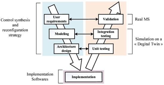
Figure 1.
Design cycle of reconfigurable control.
In this paper, we are interested only in the descending branch of the V cycle (blue part), which presents the control synthesis and reconfiguration strategy. The verification steps are developed in [6].
This paper is organized as follows. In Section 2, we present the necessary state-of-the-art to place our approach. Section 3 presents the proposed approach of fault-tolerant and reconfigurable control that will be illustrated in Section 4. A discussion of our proposal is given in Section 5. Finally, in Section 6, a conclusion and indications of our future works are reported.
2. Background
In this part, we propose to place our contribution concerning the two fields of fault-tolerant/reconfiguration control and distributed control synthesis.
2.1. Fault Tolerant Control (FTC)
Introduced in the 80′, the Fault-Tolerant Control (FTC) was the aim of several research projects in the field of MS. The main objective is to cancel the problems related to the appearance of faults that can lead to undesired or even catastrophic behaviors. Indeed, this type of problem has often been avoided by relying on hardware redundancy based on actuators and sensors. This strategy is not only expensive, but it also requires a significant maintenance device. In this context, and in response to the new challenges posed by cost and fault tolerance, many methods and techniques based on dynamic models have been developed and analyzed analytically. These methods of FTC synthesis are generally classified into two large families: Passive Fault Tolerant Control (PFTC) and Active Fault Tolerant Control (AFTC). The distinction between these two categories depends on the method of synthesis, the faults considered, the type of redundancy present (hardware and software), and the behavior of the system in the degraded case. A PFTC, as presented in [7], allows the use of a single controller both in faulty and non-faulty behaviors; it is closely related to robust control. Even if the idea of passive approaches is attractive from a conceptual point of view, this type of solution can impose unacceptable limitations on normal closed-loop behavior. On the other hand, an AFTC, as presented in [8,9,10], requires a controller that adapts its control law to a fault occurrence. This type of strategy allows to design of one controller for the non-faulty behavior and a second controller for the faulty one using a diagnostic block. The main objective is to switch from one controller to the other one corresponding to the desired operating mode. A comparative study between active and passive methods of FTC is given in [11,12].
The research works presented so far focus on continuous systems, which are represented by differential equations. At the same time, our main contribution is proposed for MS, seen as a class of DES. Unlike continuous systems, a DES is defined as a dynamic system that can be described in a discrete state space and whose evolution is described by state transitions triggered by events [1]. Several approaches have been developed for this class of systems.
For example, in [13], the authors proposed an approach to AFTC based on three ideas. The first one is the exploitation of a multiple-supervisor architecture to actively counteract the effect of faults. The second one is the evaluation of the effect of the diagnostics algorithm on the performance of the architecture. The last one is the definition of a new diagnoser called diagnosing controller, which realizes in a unique entity the switching architecture.
While in [14], the authors suggested a method to treat FTC that ensures the safety of a DES. They consider multiple faulty modes. Each faulty mode is modeled by an automaton. This latter, with the normal mode automaton, describes a DES with faults. Each faulty mode has some illegal states that must be avoided by control so that the fault can be tolerated. In their work, they assume that FTC takes actions (disablements) only when the occurrence of a fault is certain. They also consider cases of both full-event observation and partial-event observation. They derive then necessary and sufficient conditions for the existence of FTC. Likewise, they provide formulas and algorithms to calculate control actions if the necessary and sufficient conditions are satisfied. Both offline control synthesis (for full event observation) and online control synthesis (for partial event observation) are investigated.
Another proposition is given in [15], where authors designed a safe supervisory control loop architecture based on the concept of FTC and robust control. In fact, in normal process mode, the system runs without any failure. In this mode, the supervisor must bind the system behavior into the desired language. Upon the occurrence of the loss of observability of some observable events, the system gets into a not detected failure process mode. In this case, the supervisor may allow the system to run out from the desired behavior but must prevent it from running into some disaster or unrecoverable situations (states). The proposed architecture is based on modular modeling of the supervisor (detailed in [16]). Each module is responsible for keeping the system running in the desired behavior in normal mode. Several modules’ purpose is to prevent the system from running into a disaster situation after the loss of observability of their corresponding event and before this loss may be detected. The overall supervisor is obtained as the joint control action of all of these supervisors. Supervisors act simultaneously as supervisors and diagnosers, as they report the occurrence of a failure as they observe some event that is not compatible (feasible) with their own realization.
The problem of AFTC in the framework of DES modeled as automata is discussed in [17]. Starting from an appropriate model of the system, they recall the notion of safe diagnosability as a necessary step in order to achieve fault-tolerant supervision of DES. Then, they introduce two new notions: “safe controllability”, which represents the capability, after the occurrence of a fault, of steering the system away from forbidden zones, and “active fault tolerant system”, which is the property of safely continuing operation after faults. Moreover, they show how it is possible to define a general control architecture to deal with the FTC problem by introducing a special kind of automaton called a “diagnosing-controller”.
Since most AFTC approaches rely on a centralized architecture, the recognition of faults can be quite challenging. As a result, there is a growing interest in utilizing a distributed approach that would provide a clearer perspective on the detection of faults. This paper proposes a new distributed approach of AFTC based on control reconfiguration, where a new control law based on SCT is designed to reconfigure the old one corresponding to the normal behavior in case of sensor fault detection.
2.2. Towards a Distributed Control Synthesis
The SCT (Figure 2) initiated by Ramadge and Wonham (R&W) [5] aims to synthesize a supervisor (SUPG), which ensures that the behavior of a given system G remains in the desired behavior defined by a set of specifications K. The plant behavior model of the uncontrolled system (PG) represents the formal abstraction of the system and indicates the relationship between the input and the output signals without feedback, usually determined by the physical properties of the system in the form of a Finite State Machine (FSM). In order to constrain the free behavior of the system, it is necessary to define specifications that are also modeled by an FSM.
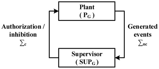
Figure 2.
SCT-based centralized control.
The synthesis algorithms automatically generate the most permissive supervisor allowing to restriction of the behavior of the system while respecting the specifications K. The system is modeled as an event generator which can belong to the set of controllable (zi ∈ Σc) or uncontrollable (ei ∈ Σnc) events. The supervisor (SUPG) acts by authorizing or inhibiting the controllable events which may be generated by the system in a given state. However, uncontrollable events are not subject to the influence of the supervisor. A behavior is then said to be controllable [18] if the occurrence of any possible uncontrollable event that may be generated by the system at a given time maintains the behavior of the system within the set of specifications K.
A brief history that summarizes the SCT of DES as it has evolved is given in [19]. Several approaches dealing with reconfiguration and fault-tolerant control have been proposed in this research axis.
In [20], the authors discuss a procedure based on SCT to reconfigure a controller with a view to avoiding a complete redesign. The reconfiguration approach holds the behavior that does not change and eliminates the one that becomes useless, resulting in fault detection and adding new behavior. Moreover, the SCT guarantees that the requirements are still respected when a synthesis is accomplished. Thereby, a partial reconfiguration using SCT keeps respecting the requirements that do not change and ensures that the new ones are also respected in the new control law.
In [21], a framework of control reconfiguration of DES that carries out fault detection is presented in order to reconfigure control and ensure that certain desired requirements are met. In the case of fault detection, the controller is reconfigured. Throughout the post-fault duration (as well as before the reconfiguration), the controlled system should satisfy the given post-fault specifications. Finally, the control problem is mathematically developed, and a condition for reconfigurability is provided.
In [22], the authors study fault-tolerance in the supervisory control context. They consider a DES where some events could not be possible in case of a fault occurrence. First of all, they determine necessary and sufficient conditions for the existence of a supervisor that respects a given set of specifications in the non-faulty behavior as well as the faulty one. Moreover, they prove that it is possible to identify a supermall fault-tolerant sublanguage if the existing condition is violated. Finally, they suggest a computation algorithm for this sublanguage and show it is correct. Another concept of fault hiding control reconfiguration (FHRC) is to ensure FTC is avoided [23]. The (FHRC) main purpose is to hide a fault from the nominal controller, whereas the closed-loop reconfigured system has an acceptable behavior. The essential freedom degrees are established by a reconfiguration block that is placed between the faulty plant and the nominal controller. The authors intend to ensure a complete, non-conflicting, and controllable behavior of the self-reconfiguring of the system’s closed loop. Thus, the nominal controller and the reconfiguration block design are entirely dissociated. For more details on fault hiding control and reconfiguration, see [3].
The state space explosion is considered one of the major drawbacks of using traditional SCT. In general, if the studied system is not complex, the centralized control approach based on SCT is sufficient to synthesize a single supervisor. However, to model a large-dimensional system made up of several subsystems, this approach cannot overcome the problem related to the state space explosion. Indeed, the total number of states of the system model increases with the number of Plant Elements (PE) constituting it [2,24]. The state space is defined by a dimension “2N” if the number of variables constituting the system is defined by N. However, for modeling an MS, two events must be associated with each variable (sensor/actuator). These two events correspond to the rising and falling edges of each variable. Consequently, the dimension of the state space rises to “22N”, which leads to a significant combinatorial explosion and also to problems of interpretation of the models when the systems to be studied are constituted of several elements.
To overcome these problems of state space explosion and modeling complexity, decentralized and distributed synthesis approaches have been proposed. These approaches assume that the behavior of the plant is limited by several local specifications. The approach thus synthesizes a supervisor to apply each of these specifications separately. Decentralized supervisors [25] operate cooperatively according to conjunctive decision fusion rules (coordinator) to form an overall decision that describes the same commanded behavior as that of the centralized or monolithic supervisor.
In general, decentralized supervisors ignore their overall interactions. The result can present a conflict that leads to a deadlock. The problem is, therefore, to effectively coordinate the decentralized supervisors to ensure overall non-blocking behavior, as the centralized supervisor would have guaranteed. In other words, the decentralized approach requires global coordination, which may also be impossible to calculate and implement for large systems.
In order to overcome this difficulty, approaches based on distributed synthesis have been proposed [26,27]. These supervisors are considered intelligent agents who ensure communication between them to exchange information on the occurrence of an event which is essential for control (Figure 3). It is proven that the behavior of the resulting distributed supervisors is identical to the monolithic or decentralized behavior presented above but which is determined in the form of less complex models [24].
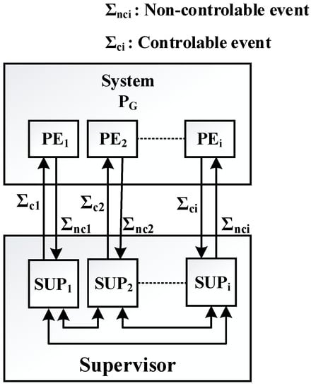
Figure 3.
Distributed supervisors.
Several approaches for FTC and control reconfiguration have been proposed in this research axis.
In [28], the authors propose a framework for distributed control reconfiguration for MS. The main idea is to design a distributed MS that integrates heterogeneous technologies of facilities that are geographically distributed. Due to the heterogeneity of the environment, the method explores concepts of different techniques and takes the best practices from each one. Mechanisms for reconfiguration are proposed using holonic and multi-agent systems techniques. The service-oriented architecture concept is applied to define the interfaces for communication.
A method to ensure fault-tolerant and distributed control is investigated in [29]. The authors review the design aspects of the fault-tolerant distributed control system, including specific strategies for processor and input/output redundancy. Then, they discuss the results of component and system reliability achieved through the fault-tolerant design as well as the implications of their results for the user.
While in [30], the authors survey the notion of fault in the supervisory control of DES, especially the results on fault-tolerant, robust, and reliable supervisory control. The main purpose is the investigation the functionality of distributed DES in faulty conditions. The insights help the designers to understand under what faulty conditions a cooperative supervisory control scheme remains valid and how to synthesize the supervisory control of DES as fault-tolerant as possible.
In [22,31], a reconfiguration for DES is proposed based on the identification of different configurations of the system by changing the supervisory control loop. The authors study the reconfiguration control design for RMS, which contain multiple components. They create a modular supervisor for each configuration and system component for the purpose of realizing each active configuration and switching between configurations.
The reconfiguration approach presented in this paper is based on a distributed architecture for controlling MS. Distributed control will be provided by several controllers. Unlike the supervisor, the controller further restricts the behavior of the system by integrating not only what the system must not do (the notion of supervisor) but also what the system must do (the concept of the controller). Therefore, the models of the resulting controllers are less complex than those of the supervisors. Each distributed controller is associated with a subsystem constituting the overall system. In addition to its set of observed events received directly from the operational part of the subsystem, each controller also uses the observed events received from other controllers. Distributed control synthesis is characterized by its flexibility [32,33,34] and its ease of being modified and configured [35].
3. Results Principle of the Proposed Methodology for the Control Reconfiguration
The reconfiguration process can be triggered by events related to a product or to production resources. A change in production can be related to the nature of the production, the quality, or the quantity of the products. In general, these changes may result in the addition and/or removal of some hardware resources in the current production. In addition, the change of state of a production resource is characterized by two events which are failures and repairs. In case of failure appearance, the reconfiguration process should first seek to replace the failed resource with another. The goal in this context is to use hardware redundancies to replace the failed element.
A reconfiguration process implementation depends on the trigger event and the time constraints exerted on the system when the event takes place. Two further situations can be considered: (i) the initiation of a new production process when the system is in a halted state and (ii) a system failure occurs during operation [36]. The proposed approach in this paper is within the second case.
Loads of proposed solutions in industry and research lean on hardware redundancy to resolve a system component failure, which might be expensive due to the technology and MS component’s maintenance. Hence, to avoid redundancy, a distributed and reconfigured control approach based on the timed information of DES (Figure 4) is proposed in this paper. The idea here is to conceive a reconfigurable control that has the capability in case of a sensor fault event detection to adapt and exploit the still available services offered by the plant. Despite the faults that may disturb a normal behavior of a DES, the reconfiguration process can maintain it by replacing the system’s current state with a target state that belongs to a degraded behavior. The estimated time of operation of each sensor is described by timed estimators. These can then be provided to replace the lost information on a faulty sensor [37].
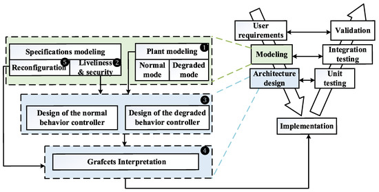
Figure 4.
Formal architecture for reconfigurable and fault-tolerant control synthesis.
➊ In order to establish a degraded behavior controller over a reconfiguration request, The plant normal behavior modeling previously presented in works [38,39] is enlarged to timed modeling where events are integrated to substitute the faulty elements’ behavior.
➋ The liveliness (what the system must do) and safety (what the system should not do) specifications are defined by Boolean logical equations that are interpreted afterward into extended finite state automata to ease the control synthesis stage and to minimize the resulting model’s combinatorial explosion.
➌ To synthesize a normal and degraded behavior controller, an adaptation of the SCT is applied to ensure the operation continuity by a redundancy of the control. A distributed architecture is used in order to avoid the combinatorial explosion associated with the operation of a centralized architecture.
➍ The resulting Controllers are translated into Grafcet [40] according to interpretation rules to be understood by operators and implemented in one of the standard languages of PLC.
➎ A reconfiguration set of specifications described by logical equations is introduced to ensure the swap between normal and degraded behaviors modes. In the main time, this set of specifications is translated into Grafcet to handle the two controllers’ grafcets.
3.1. Plant Modeling
The modeling of MS is based on its structural description. The model to be designed is more or less detailed and depends on the modeling tool and the purpose for which the system is being studied. Given that we are studying the reconfiguration of the control following the detection of the sensor, it is necessary to model all the elementary events associated with the elements making up the system. In this section, we present the recommended approach to model the two normal and degraded behaviors of the plant, as well as the modeling tool used.
The plant’s normal behavior modeling is based on the use of an FSM receiving events from the control part (CP) and acting on its system input events so as to express the reactions of its plant. In addition, models should take into account the technology of the hardware used, as well as the system environment. These models can be obtained from the relationships between the inputs and outputs of the control system.
In this paper, the interpretation of Balemi [41] is used. The set of controllable events Σc represents all the outputs of the control part (the orders to be sent to the actuators), with “↑z” for the activation of the control orders and “↓z” for their deactivation. The set of non-controllable events Σnc represents all the inputs of the control part (the logic values of the sensors), with “↑e” for reading “1” and “↓e” for reading “0”. We then have Σc = ↑zi ∪ ↓zi et Σnc = ↑ei ∪ ↓ei.
The plant normal behavior model is based on the modeling proposed in [38]. The main idea is to separate the plant into several plant elements (PE) and then define the model of the detectors and the model of the actuators. The Detectors Model (Detectors_N) describes the normal behavior of all the sensors constituting each PE of the system, and the Actuator Model (Actuators_N) describes the normal behavior of each actuator with its sensors. The PE model is then obtained by synchronizing these two models. The models of each PE are not synchronized to achieve a distributed reconfiguration of the control.
Formally, the PE normal behavior model (PEN) is defined by the automaton AN = {QN, ΣN, δN, , } with:
QN: is the finite set of states of AN
ΣN: is the set of events of AN such that ΣN = ΣNT, with ΣNT are the set of untimed events
δN: is the transition function. A transition is defined by: δN (, σ) = , σ is an event of ΣN
: is the initial state of the AN automaton, such that ∈ QN
: is the set of states marked in AN such that ⊆ QN
The set of normal PE behaviors is defined by the GN set, such as:
GN = where n is the number of PE constituting the studied MS.
Several extensions of DES have been proposed to provide broader functionality and richer specifications. One of the oldest is based on temporal logic [42]. An MS is subject to time constraints such as, for example, the start time of the task or the duration of the tasks. This information can be used to calculate more permissive control laws. Taking time into account introduces a new dimension in DES modeling and facilitates the control of a considerable number of applications, but it can also generate significant complexity in terms of states.
Based on earlier work [43] on temporal logic, a timed version of DES called “timed discrete event systems (TDES)” was introduced [42]. The authors extend the theory of R&W by introducing the notion of forced events and time constraints. The passage of time is modeled by the occurrence of a particular event denoted by a tick. This approach offers good solutions for controlling TDES. However, the discrete nature of time generates an exponential explosion in the number of states.
In order to solve this problem and unlike the approaches based on models where time is discrete, some authors propose approaches based on dense time models [44] because it is more natural for physical processes operating in continuous time. In this model, timed events are real numbers that increase monotonously without limit. Dense time processing in a framework of FSM is difficult because it is not easy to transform a time-dense trace set in an ordinary formal language. It is for this reason that the theory of formal timed languages and timed automata were developed.
However, we can wonder about the relevance of the use of these formal and mathematical tools. The semantics of timed automata models are very precise and require immediate transitions and infinitely precise clocks. Consequently, no execution platform allows such a precise implementation of such an automaton [45].
In addition, even if several tools have been developed for timed model-checking, there is nothing to ensure that the properties verified on the theoretical models are preserved during implementation. We are talking about “implementability” and property preservation problems after the implementation of timed automata models.
For all these reasons, our choice was oriented towards FSM while integrating the notion of time.
As part of our work, to set up the control reconfiguration, we need to introduce the notion of faulty events and, in fact, the occurrence of timed events in order to compensate for the faulty element and avoid the use of hardware redundancies. For this, we propose a time integration method based on FSM as a modeling tool while avoiding the complexity of models recurring in [42]. The timed model is an extension of the automaton of normal behavior AN. Indeed, the set of events previously presented consisting of non-timed events becomes a set of events made up of two types of events: non-timed and timed events. This leads, in particular, to a change in the determination of the transition functions.
We propose to represent time with a clock, and it is considered an event. This hypothesis is interesting because it facilitates the modeling task using FSM. The duration defines the time it takes for a sensor to be activated or deactivated after checking a specific condition.
The degraded behavior model equivalent to the normal behavior of a PE (PEF) is then obtained by the synchronization of the two-timed models of detectors (detectors_F) and actuators (actuators_F).
Formally, the model (PEF) is defined by the automaton: AF = (F, ΣF, ), such as:
F: is the finite set of states of AF.
ΣF: is the set of events of AF, such as ΣF = ∪ , with is the set of timed events such that: = ↑ckk ∪ ↓ckk ∪ dk with ↑↓ckk is the event associated with the activation and deactivation of the clock, and “dk” is the event associated with the duration of the clock (dk = 1 if the duration has elapsed).
: is the transition function. A transition is defined by: (, σ) =. σ is the occurrence of a timed event or not of ΣF.
: is the initial state of the AF automaton, such as ∈ QF.
: is the set of states marked in AF such that ⊆ QF.
The set of the PE degraded behaviors is defined by the GF set, such as:
GF = where n is the number of PE constituting the studied PE.
The set of PE models describing the global system is then defined by: G = GN ∪ GF.
3.2. Local Control Synthesis
The objective behind a local synthesis control application is to establish controllers that can describe the desired local behavior of each PE. For this purpose, local specifications must be defined to restrict each behavior of the PE to the desired local behaviors.
In the classical approach of the control synthesis of DES [5], the constraints are expressed by FSM. However, this can generally present problems in the design and interpretation of models. To resolve these problems, we adopt, for the control integration, an approach based on Boolean logical equations consisting in constraining each PE until its desired operation. Writing constraints by logical equations facilitate the representation of sequences of events and reduces the combinatorial explosion inherent to the use of FSM.
The use of Boolean logical equations has the advantage of describing the constraints in a precise, modular, and flexible way in a language familiar to the expert. This makes it possible to resolve the problem of the heaviness modeling by a single automaton gathering all the specifications to be respected.
The specifications of the system represent the behavior of the operations to be performed (or not) by the system. They are expressed in the form of security constraints and liveliness. The integration of specification constraints aims to inhibit actions and/or organize and sequence the execution of orders sent to the system. A specification cannot cause additional actions in a model but can express a restriction or inhibition of these actions. The specifications can be applied globally to the whole system or locally to each element of the plant.
The local specifications represent a set of safety and liveliness constraints applied locally to each PE. Each constraint is defined by a logical implication given by the following formula:
where “q” is a state of the set of states of G, and “y” is a controllable event. The implication above means that if “q” is true, then “y” is prohibited.
q .y = 0
A local controller (LC) can describe the normal local (LCN) and degraded (LCF) behavior of each PE. A local controller can operate separately from other designed controllers. To obtain the automatons of the LC of the normal and degraded behaviors AN (LC)/AF (LC), a synthesis of AN and AF models with the set of specifications to be respected is applied.
3.3. Global Control Synthesis
An MS running often evokes synchronism and parallelism between its different PE. Thereby, a PE may depend on another one to guarantee the desired behavior. Therefore, communication between several PEs is necessary. To achieve that, a global control synthesis is needed to obtain Distributed Controllers (DC) for both normal (DCN) and degraded (DCF) behaviors that can behave in both local and global contexts.
Global specifications represent a set of safety and liveliness constraints interacting on several PE. They are defined by a logical implication given by the following expression:
If (cg) Then {y = 0 else y = 1}
With: cg = c + d
After checking the condition “cg” (true), the action “y” is inhibited (y = 0). Otherwise, the action “y” is authorized (y = 1). If the “c” sensor associated with the “cg” constraint is faulty, the duration “d” associated with its activation or deactivation state compensates for its functioning.
3.4. Distributed Controllers Interpretation into Grafcet
Although the SCT has been widely accepted in academia and some of its applications in the industry have been presented in the literature [41,46,47,48], its industrial application remains difficult. This is mainly due to the problems encountered during the “physical” implementation of the SCT when the model to be processed complex.
At the beginning of the 70s, the need to describe increasingly complex controllers, which the implementation of would be facilitated by the development of microprocessors, became evident. PLC then appeared, and a controller modeling tool with the objective of being implemented in a PLC became necessary.
The Grafcet is one of the tools which provides a clear understanding of the behavior of inputs/outputs of an MS. it also allows one to model the different types of inputs/outputs and know when a particular input change can modify the state and/or the output of the MS. This tool was defined by the AFCET [40].
Today, the Grafcet is well accepted in the industry thanks to its graphical interface and especially thanks to its wide distribution in the education system and in the industry from the end of the 70s rather than the Petri Net (PN) [49], which are graphic models and mathematics preferably used in the academic world for formal methods of DES analysis. It is for all these reasons that our choice turned to the Grafcet as an interpretation tool for distributed controllers of normal behavior (DCN) and degraded behavior (DCF). It is up to the user, then, to choose the according to PLC programming language.
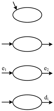
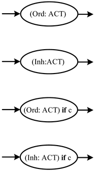
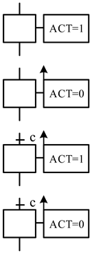
Several interpretation rules for grafcet are given by the authors in [38]. A state of a DCN/DCF is interpreted by a grafcet step, while a transition of a DCN/DCF is transformed into a transition receptivity of the corresponding grafcet. We add to these rules an interpretation of timed events. In a grafcet translation, the activation and deactivation of the clock are not interpreted. Only the duration is presented. The transition marked “d” on the DCF is interpreted by a transition receptivity in the form of (d/Xk), which means that if the variable associated with step “k” is activated, this one must be maintained. Until the time elapses, which causes the transition to the next step, “k + 1”. The authorization of an order (Ord: ACT) is translated into an action forced to 1 (ACT = 1), while the inhibition of the order (Inh: ACT) is transformed into an action forced to 0 (ACT = 0). If a global condition is associated with the authorization or the inhibition of the order, it results in receptivity to the transition, which precedes the step associated with the action (ACT = 1) or (act = 0) (see Table 2).

Table 2.
Interpretation rules.
3.5. Modeling of the Reconfiguration
After the interpretation of the various distributed controllers of the two operating modes in grafcet and before any implementation in a PLC, it is necessary to define the conditions for switching and reconfiguring from normal mode to degraded mode and vice versa when a fault is detected or repaired.
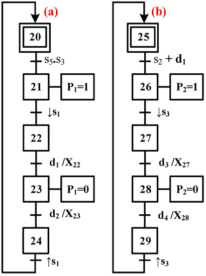
Let G7(N) be an extract from the control grafcet of the normal behavior of any PE, and G7(F) an extract from its control grafcet equivalent to normal (or degraded) behavior presented in Figure 5.
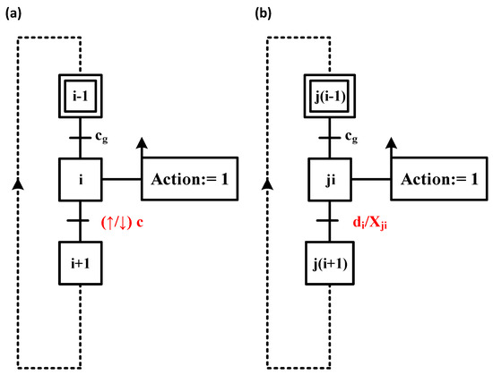
Figure 5.
Grafcets extracts (a) G7(N), (b) G7(F).
The denoted reconfiguration condition (RC) is defined by the following logical equation:
RC: If Xi and fc = 1 Then
- F is the forcing operation
- G7(N) is the grafcet associated with the distributed controller of normal behavior
- G7(F) is the grafcet associated with the distributed controller of degraded behavior
- Xi is the Boolean variable associated with step “i” of G7(N)
- Xji is its corresponding variable associated with the “ji” step of G7(F)
- fc is the detected fault of sensor c
The expression of Equation (3) means that if Xi is active and a sensor fault is detected (fc), a switch is applied to the degraded mode by forcing the grafcet G7(F) to be activated in step Xji (step equivalent to Xi in normal behavior) and by deactivating the grafcet of normal mode G7(N).
This equation is subsequently interpreted in grafcet (Figure 6) to manage the two grafcets of the two operating modes of each PE. Interpretation is defined as follows:
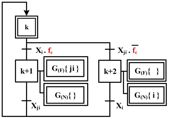
Figure 6.
Interpretation of the reconfiguration constraint in Grafcet.
- The two constraints conditioned by “If” are interpreted by transitions receptivity just after the initial step at the level of the reconfiguration grafcet.
- The “Else” expression corresponds to a choice and is then interpreted by an “Or” divergence at the grafcet level.
- The actions to be performed after the expression “Then” are translated into actions corresponding to grafcets forcing orders.
To make sure freeing the operation of grafcets G7(N) and G7(N), a check of the steps in which the two grafcets are forced is added in transition receptivity just after the forcing step.
4. Illustration Example
4.1. Presentation of the Example Illustration
The MS used in this example is a transfer of boxes (Figure 7). It is a distributed system instrumented with six sensors, a push button, and four actuators. It consists of transferring boxes generated by the loading station to an unloading station via two conveyors. The passage between these two conveyors is ensured by two pushers.
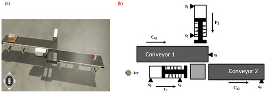
Figure 7.
(a) boxes transfer system, (b) the system’s actuators and sensors.
4.2. Plant Modeling
The system consists of four plant elements (PE): pusher P1, pusher P2, conveyor Cb1, and conveyor Cb2. The first step is to model these PEs for normal behavior. This modeling is ensured by the practical model [39] using the PEs events associated with each actuator and its appropriate sensors.
Figure 8 details the modeling of the pusher P1 and the conveyor Cb2. The PE model corresponding to the pusher P1 is an automaton obtained by the synchronous composition of the sensors and actuator models of this element. The sensors model is presented by an automaton depending on the number of sensors associated with P1 (s1 and s2).
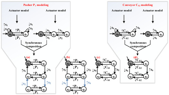
Figure 8.
Normal behavior models of (a) P1, (b) P2, (c) Cb1, and (d) Cb2.
The actuator model is presented by an automaton that depends on the pusher combined with the sensor’s events associated with this actuator.
This approach is applied to the four PEs constituting the studied system. The automata describing the set of normal behaviors of the four PEs are shown in Figure 8.
The pusher (P1) and conveyor 1 (Cb1) automata are defined as follows:
- (a):
- AN(P1) = {QN(P1), ΣN(P1), δN(P1), , } such as:
- QN(P1) = {q0, q1, q2, q3, q4, q5}
- ΣN(P1) = , avec: = ↑↓Z ↑↓E with: ↑↓Z = {↑P1, ↓P1} et ↑↓E = {↑s1, ↓s1, ↑s2, ↓s2}
- = q0
- = q0
- (b):
- AN(cb1) = {QN(cb1), ΣN(cb1), δN(cb1), , } such as:
- QN(cb1) = {q0, q1, q2, q3}
- ΣN(cb1) = , avec: = ↑↓Z ↑↓E with: ↑↓Z = {↑Cb1, ↓Cb1} et ↑↓E = {↑s5, ↓s5}
- = q0
- = q0
In the same way, we obtain the two automata describing P2 and Cb2. The different models obtained describe all the possible evolutions of the actuator with its sensors.
The second step consists in modeling the system’s PEs for a degraded behavior where the sensors s2 and s4 are considered faulty elements. Let fs2 (resp. fs4) be the fault of sensor s2 (resp. s4) associated with the output of pusher P1 (resp. P2). The modeling of these PEs, in this case, is an extension of the models given in Figure 8 by adding timed events that replace information on s2 and s4, as shown in Figure 9.

Figure 9.
Degraded behavior models of: (a) P1, (b) P2.
The degraded behavior model of P1 is presented by the following automaton:
- (a):
- AF(P1) = {QF(P1), ΣF(P1), δN(P1), , } such as:
- QF(P1) = {q0, q1, q2, q3, q4, q5, q6, q7}
- ΣF(P1) = , avec: = ↑↓Z ↑↓E with: ↑↓Z = {↑P1, ↓P1} et ↑↓E = {↑s1, ↓s1} et = {↑ck1, ↑ck2, ↓ck1, ↓ck2, d1, d2}
- = q0
- = q0
The two obtained models describe all the possible evolutions of the pushers P1 and P2 according to their sensors and their appropriate clocks.
Among these evolutions, after the deactivation of the sensor s1 of the model (a) of Figure 9, a deactivation of the order P1 from the state q2 is possible before the activation of the clock ck1. This evolution is not desired and will be removed later by integrating local specifications.
4.3. Local Control Synthesis
To synthesize the local controllers corresponding to each PE, a determination of the set of local specifications is necessary. This set is defined to obtain the behaviors of the four PEs in the case of normal behavior and the degraded one of pushers P1 and P2. Table 3 presents the local specifications to be applied to the different PE for each behaving mode.

Table 3.
Set of local specifications.
For example, the specification (10) is expressed by (q5 + q7). ↑P1 = 0 reflects the fact that the event ↑P1 corresponding to the permission of the output order of pusher P1 cannot appear in both states q5 and q7. Indeed, ↑P1 is authorized only in the initial state. Any other transition associated with this event is deleted. The PE model of pusher P1 is checked state by state following the evolution of the model, and at each state, the set of local specifications is checked, then the transition associated with the denied event is deleted.
Even if the two behaving modes are equivalent, a state shift is observed between specification 2 (resp. 4) and 10 (resp. 12). This is due to the integration of time information which leads to the addition of a state for each clock introduced in the degraded model.
To apply the control synthesis, the specifications defined in Table 3 are interpreted in the form of an extended finite state machine [50]. Using SCT synthesis, we obtain the local controllers LCN/F. Each one of them describes the desired local behavior of each PE according to normal (Figure 10) and degraded (Figure 11) behaviors.

Figure 10.
Local controllers LCN. (a) P1, (b) P2, (c) Cb1, (d) Cb2.

Figure 11.
Local controllers LCF. (a) P1, (b) P2.
In normal behavior mode, the pusher’s deactivation «↓P1» (resp. «↓P2») is ensured when sensor s2 (resp. s4) is activated (pusher in extended position).
However, when sensor fault {fs2, fs4} appears, the information lost on these two sensors is replaced by timed information. Indeed, when P1 (resp. P2) begins to go out, its associated input sensor s1 (resp. s3) is deactivated, and the clock ck1 (resp. ck3) is triggered for a duration d1 (resp. d3) which is the time required for the pusher to reach sensor s2 (resp. s4). Once the duration has elapsed, the clock ck1 (resp. ck3) is deactivated, which causes the deactivation of the order P1 (resp. P2), then the activation of the clock ck2 (resp. ck4) for a duration d2 (resp. d4) which is the estimated time to deactivate s2 (resp. s4).
4.4. Global Control Synthesis
The controllers presented above act locally. In order to ensure overall’s system behavior and control where these controllers can communicate with each other, global specifications are added. The global specifications of the transfer system are shown in Table 4.

Table 4.
Set of global specifications.
The third specification refers to the fact that the order P1 is allowed if the pusher P2 is in its retracted position, which is expressed by s3 = 1, and if a box is detected in front of the pusher 1 expressed by s5 = 1. The fourth specification refers to the fact that the P2 order is allowed if pusher 1 is fully extended and expressed by s2 = 1. If this sensor is faulty, the duration associated with its activation replaces the information s2 = 1.
Two types of distributed controllers (DC) are distinguished: DCN for normal behavior and DCF for degraded behavior. In order to synthesize the controllers {DCN, DCF} corresponding to the studied system, two steps are to be carried out: (i) the aggregation of the local controllers LCN and LCF resulting in Section 4.3 and (ii) the consideration of the global specifications expressed in Table 4.
The first aggregation consists of merging the non-timed events of the LCNs and LCFs, i.e., {↑P1, ↓P1, ↑P2, ↓P2, ↑Cb1, ↓Cb1, ↑Cb2, ↓Cb2} into macro-states.
The second aggregation is only applied to the timed events of the LCFs {↑ck1, ↓ck1, ↑ck2, ↓ck2, ↑ck3, ↓ck3, ↑ck4, ↓ck4}, which are merged into linked macro-states by the uncontrollable events {↑s1, ↓s1, ↑s3, ↓s3} and timed events {d1, d2, d3, d4}.
Once the models of the local controllers have been aggregated, the untimed controllable events {↑P1, ↑P2, ↑Cb1, ↑Cb2} belong to the Ord set (set of allowed orders), while {↓P1, ↓P2, ↓Cb1, ↓Cb2} belong to the Inh set (set of inhibited orders).
Timed events {↑ck1, ↑ck2, ↑ck3, ↑ck4} belong to set Ack, while events {↓ck1, ↓ck2, ↓ck3, ↓ck4} belong to set Dck. In order to obtain the distributed controllers DCN and DCF, the global specifications must be taken into account and added to the local aggregated controllers.
The distributed controllers DCN of the transfer system are shown in Figure 12. The controllable event ↑ P2 is merged into the initial state of the model DCN/F(P2) and belongs to the set Ord. According to the verification of the global specification {s2 + d1 = 1}, the order P2 is authorized (Ord: P2). Indeed, if s2 = 1, then P2 is authorized. If not (s2 is faulty), then the duration d1 necessary for the activation of s2 replaces the faulty sensor.
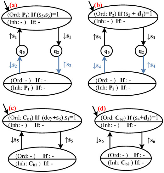
Figure 12.
Distributed controllers of the normal behavior of (a) P1, (b) P2, (c) Cb1, (d) Cb2.
In Figure 13, once the sensor s3 is deactivated, the clock ck3 is triggered, and the event presenting its activation is merged into a macro-state just after the transition labeled ↓s3 and belongs to the set Ack. The deactivation event of this clock is merged into the same macro-state containing the inhibition of order P2 (inh: P2) and belongs to the set Dck. ck3 is activated following the deactivation of s3 and deactivated after the elapse of the duration of d3. Therefore, no global specification is needed for (Ack: ck3) and (Dck: ck3). We perform the same for ↑ck4, ↓ck4, and d4.
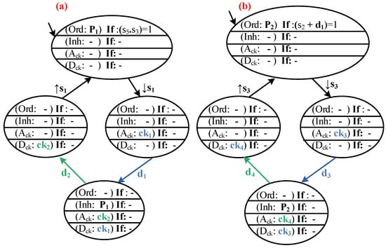
Figure 13.
Distributed controllers of degraded behavior of (a) P1, (b) P2.
4.5. Distributed Controllers Interpretation into Grafcet
By applying the interpretation of Table 2 presented previously to the non-timed and timed distributed controllers of the transfer example studied, we obtain the following grafcets:
The resulting grafcets can be considered as generic models for this type of actuator regardless of the system to which they belong. On the other hand, the global specification must be modified according to the working environment of these actuators. Therefore, these grafcet models can be elements of a control element library.
4.6. Modeling of the Reconfiguration
In order to switch from normal to degraded behavior grafcets where fs2 and fs4 are detected, some reconfiguration rules must be determined. In the case of fs2 detection, a change from GN(P1) to GF(P1) is necessary. Based on (Equation (3)), we obtain the reconfiguration rules below for the pusher P1:
(F: GN(P1) {X2}) and (F: GF(P1) { })
(F: GN(P1) {X3}) and (F: GF(P1) { })
The same principle is adopted in the case of fs4 detection. In order to manage the switch from the grafcet model with normal behavior to the grafcet model with degraded behavior, the reconfiguration rules must be interpreted in a grafcet formalism for an implementation purpose in a PLC. The reconfiguration rules determined by the equations CR1(P1) and CR2(P1) are given in Figure 16.
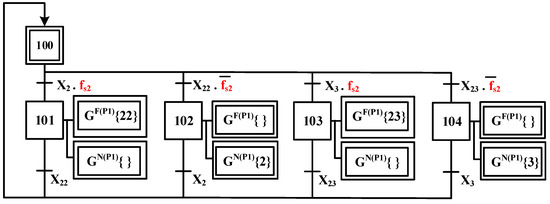
Figure 16.
Grafcet interpretation of reconfiguration rules.
The implementation of grafcet models of normal/degraded behavior and reconfiguration rules ensure fault tolerance when sensor faults fs2 and fs4 are detected. Therefore, a continuity of the desired behavior of the system is maintained despite the faults that hinder its normal behavior.
5. Discussion
The problem of controlling DES has been the subject of many studies. For this type of system (DES), it is necessary to have a control law ensuring good behavior according to the controlled process structure and state. In [5], the authors proposed the theory of “Supervisory Control” to model the control of a DES using the FSM formalism. The SCT proposes to synthesize the control of a process by distinguishing, on the one hand, the model of the system’s potentialities (open-loop behavior) and, on the other hand, the operating constraints imposed on the system (specification model). However, this approach presents several disadvantages of its use.
Complex systems imply a monolithic model which is exposed to combinatorial explosion. In fact, if the plant is presented under a size n and the specifications model is presented under a size m, the resulting controller size is given by k = m n. In order to overcome this issue, our work is based on a distributed control where the system studied is divided into several PEs. Therefore, each PE has a distinct controller. In the case of a sensor fault occurrence, only the controller of the faulty PE is reconfigured, which avoids the reconfiguration of the whole controller as proposed in monolithic approaches [20,22,23,51].
The second drawback of the classical SCT approach is the difficulty of implementing it into a real manufacturing controller. In fact, the existing contributions focus on how to transform the supervisor into the software, and the hardware aspect of the concrete controller is neglected. Indeed, it leads to problems in controller implementation as synchronization and simultaneity. In addition, the SCT is used on a DES, which is by definition a “discrete-state, event-driven system”. Its state evolution depends entirely on the occurrence of asynchronous discrete events over time [1]. For a PLC implementation, the controller respects a cycle time (input reading, program execution, output update) where several variables may change simultaneously, so the asynchronous hypothesis is not guaranteed. The grafcet interpretation used in this work represents an intermediate step before implementation. Indeed, grafcet specifications can be easily translated into a PLC language. For this, the classical translation called self-holding programming [52] (or self-maintaining circuit) is commonly used.
The proposed distributed reconfiguration approach gives the possibility to avoid the composition between models, which is the origin of the combinatorial explosion of the state space. The methodology suggests that every PE has normal behavior and degraded behavior controller models, and a grafcet reconfiguration. Nevertheless, there is an obvious chance for the operator to lose the overall vision of the specifications in the case of complex systems due to the grafcet multiplications. Thus, a verification of the distributed controller along with the established reconfiguration grafcet is due before any implantation. This phase is based on two verification steps, first the designed control deadlock’s property and second the grafcets reachability property during reconfiguration for both normal and degraded behaviors.
Since the grafcets are automatically generated, their encoding is always presumed to be correct if the translation rules are properly followed by the designer. Hence before the implementation in a PLC and to avoid errors made by designers during the specification modeling phase, a verification model (checker-model) is applied on each distributed controller.
The various distributed grafcets of normal and degraded behaviors, as well as the grafcets ensuring reconfiguration, are translated into structured text language (ST) and verified using the UPPAAL software [53]. The new scheme of the proposed methodology of the control reconfiguration is shown in Figure 17, to which we added à 6th step ➏ consisting of verifying formally using a checking model the deadlock and the reachability properties of all the grafcets resulting from the application of the reconfiguration approach. More details are discussed in [54].
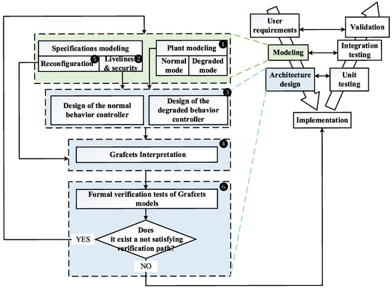
Figure 17.
Formal architecture for a reconfigurable and fault-tolerant control synthesis adding a verification phase.
6. Conclusions and Future Works
Nowadays, manufacturing systems have to evolve become more complex, and adapt dynamically to the working environment, which is defined in the industrial field by Smart Manufacturing Systems (SMS) or so-called industry 4.0, where everything can be connected, simulated, and reconfigured. It is no longer appropriate to only detect and locate a fault but also to provide a solution for the operator to interact with his system. Being able to formally guarantee the safety of MS and increase its productivity is today a scientific issue with significant industrial challenges. In order to respond to the operational safety issues in the field of systems control, the implementation of formal methods is necessary. In this context, it is important to monitor manufacturing systems (MS) and to offer an alternative solution to maintain production. Thus, a reconfiguration of the MS control is required. For this aim, this paper has presented a new framework for a tolerant and reconfigurable control for MS.
To address these issues, the design approach for flexible, reconfigurable, and implementable controllers developed in this paper proposes:
- A flexibility notion-based reconfiguration mechanism to evaluate different control objectives to attain efficiency and reactivity. In order to ensure this flexibility control, our methodology exploits the MS distributed control architectures and determines a set of reconfiguration constraints to provide complete flexibility that allows switching between different controllers with no system downtime. The distributed control architecture can facilitate the modeling phases of the plant and the specifications to be respected [54] while avoiding the combinatorial explosion of the state space recuring in centralized control approaches.
- Redundancy is applied at the level of the controllers. For each distributed controller of normal behavior, we define its equivalent, of which we have integrated the notion of timed events to replace the estimated behavior of the faulty sensors [37,50].
- The implementation of the reconfigurable control in a PLC is ensured first by a translation of all the resulting distributed controllers and the reconfiguration specifications into grafcet. The deadlock of grafcets and the reachability conditions of reconfigured grafcets are verified by a verification and validation tool (UPPAAL).
- The method proposed for reconfiguration is without manual intervention and without additional equipment.
- While the approach has certain advantages, it has drawbacks related to the following:
- The plant modeling phase (complexity in establishing the models corresponding to each PE).
- The specification constraints modeling phase (how to ensure that they are sufficient, that they are not blocking?).
- Integration of reconfiguration specifications. As part of our work, they are interpreted by a separate grafcet managing the two modes of behavior (normal and degraded). However, these can be taken into account from the modeling phase to determine a single control grafcet where the reconfiguration can be expressed by a simple “OR” between the two behavior modes. But on the other hand, we lose the global view of the different modes of behavior, which can be very interesting information for the supervision of MS.
- Optimization of the models generated by the approach adopted for the design of the reconfigurable control.
The proposed work has advantages and drawbacks to help identify several perspectives that constitute interesting and promising paths to exploit in further research work. These leads concern:
Modeling stage: The designing of models of normal and degraded behaviors may turn out to be a difficult phase. In response to the hardness of modeling, a library of proven models linked to different PE and local controllers can be developed. The operator will then have the task of specifying the local constraints to define the distributed controllers. Hence, the modeling phase complexity is lesser. When choosing the element, the control designer is provided by the library with two models of the controllers corresponding respectively to the normal and degraded behaviors of the chosen equipment.
Optimization: the optimization of the distributed controllers interpretation step where the control grafcets are automatically generated seems feasible in the context where some generated steps can sometimes be deleted. In fact, the reading of the value “0” to “1” contained in the sensors passages of the obtained control grafcets does not affect the behavior of the system, meaning, they can be removed to reduce the resulting control grafcets.
Type of faults treated: The faults studied in this brief are associated with sensors stuck on reading a “1” or a “0” value, but an actuator fault can also be detected. In this case, it is important to have hardware redundancy to ensure the desired action.
Some prospect’ work in our lab concerns the use of machine learning methodologies to identify the nominal and abnormal modes of a system but in a task of diagnosis before reconfiguration.
Author Contributions
Conceptualization, I.T. and writing—original draft preparation, I.T.; writing— review and editing, A.P., V.C.-M. and B.R. All authors have read and agreed to the published version of the manuscript.
Funding
This research received no external funding.
Institutional Review Board Statement
Not applicable.
Informed Consent Statement
Not applicable.
Data Availability Statement
Not applicable.
Acknowledgments
The proposed work in this paper is developed as part of the FFCA project funded under the CPER 2014–2020 named PFEXCEL.
Conflicts of Interest
The authors declare no conflict of interest.
Abbreviations
| AFTC | Active Fault Tolerant Control |
| CP | Control Part |
| CS | Control Systems |
| DC | Distributed Controllers |
| DES | Discrete Event Systems |
| FHCR | Fault Hiding Control Reconfiguration |
| FS | Flexible Systems |
| FSM | Finite State Machine |
| MS | Manufacturing System |
| PFTC | Passive Fault Tolerant Control |
| PE | Plant Elements |
| PLC | Programmable Logic Controller |
| PN | Petri Net |
| RCS | Reconfigurable Control Systems |
| RMS | Reconfigurable Manufacturing Systems |
| SCT | Supervisory Control Theory |
| TDES | Timed Discrete Event Systems |
| V&V | Verification and Validation |
References
- Cassandras, C.G.; Lafortune, S. Introduction to Discrete Event Systems, 2nd ed.; Springer: New York, NY, USA, 2008; Available online: https://www.springer.com/us/book/9780387333328 (accessed on 8 December 2017).
- Zaytoon, J.; Riera, B. Synthesis and implementation of logic controllers—A review. Annu. Rev. Control 2017, 43, 152–168. [Google Scholar] [CrossRef]
- Moor, T. A discussion of fault-tolerant supervisory control in terms of formal languages. Annu. Rev. Control 2016, 41, 159–169. [Google Scholar] [CrossRef]
- Deschamps, E.; Henry, S.; Zamaï, E. The control of discrete event systems. Stud. Inform. Control. Available online: https://web.ece.ucsb.edu/~hespanha/ece229/references/RamadgeWonhamPIEEEJan89.pdf (accessed on 20 November 2022).
- Ramadge, P.J.G.; Wonham, W.M. Automatic design of control laws based on Petri nets formalism for complex Discete Event Systems. Proc. IEEE 1989, 77, 81–98. [Google Scholar] [CrossRef]
- Tahiri, I.; Philippot, A.; Carré-Ménétrier, V.; Tajer, A. A Fault-Tolerant and a Reconfigurable Control Framework: Application to a Real Manufacturing System. Processes 2022, 10, 1266. [Google Scholar] [CrossRef]
- Badihi, H.; Zhang, Y. Passive Fault-Tolerant Cooperative Control in an Offshore Wind Farm. Energy Procedia 2017, 105, 2959–2964. [Google Scholar] [CrossRef]
- Lan, J.; Patton, R.J. A new strategy for integration of fault estimation within fault-tolerant control. Automatica 2016, 69, 48–59. [Google Scholar] [CrossRef]
- Gao, Z.; Han, B.; Jiang, G.; Lin, J.; Xu, D. Active fault tolerant control design approach for the flexible spacecraft with sensor faults. J. Frankl. Inst. 2017, 354, 8038–8056. [Google Scholar] [CrossRef]
- Wang, J.; Wang, S.; Wang, X.; Shi, C.; Tomovic, M.M. Active fault tolerant control for vertical tail damaged aircraft with dissimilar redundant actuation system. Chin. J. Aeronaut. 2016, 29, 1313–1325. [Google Scholar] [CrossRef]
- Jiang, J.; Yu, X. Fault-tolerant control systems: A comparative study between active and passive approaches. Annu. Rev. Control 2012, 36, 60–72. [Google Scholar] [CrossRef]
- Blanke, M.; Kinnaert, M.; Lunze, J.; Staroswiecki, M. Introduction to Diagnosis and Fault-Tolerant Control. In Diagnosis and Fault-Tolerant Control; Springer: Berlin/Heidelberg, Germany, 2016; pp. 1–35. [Google Scholar] [CrossRef]
- Paoli, A.; Sartini, M.; Lafortune, S. Active fault tolerant control of discrete event systems using online diagnostics. Automatica 2011, 47, 639–649. [Google Scholar] [CrossRef]
- Shu, S.; Lin, F. Fault-Tolerant Control for Safety of Discrete-Event Systems. IEEE Trans. Autom. Sci. Eng. 2014, 11, 78–89. [Google Scholar] [CrossRef]
- Sánchez, A.M.; Montoya, F.J. Safe Supervisory Control Under Observability Failure. Discrete Event Dyn. Syst. 2006, 16, 493–525. [Google Scholar] [CrossRef]
- Paoli, A.; Sartini, M.; Lafortune, S. A fault tolerant architecture for supervisory control of discrete event systems. IFAC Proc. Vol. 2008, 41, 6542–6547. [Google Scholar] [CrossRef]
- Kumar, R.; Garg, V.K.; Marcus, S.I. On controllability and normality of discrete event dynamical systems. Syst. Control. Lett. 1991, 17, 157–168. [Google Scholar] [CrossRef]
- Wonham, W.M.; Cai, K.; Rudie, K. Supervisory Control of Discrete-Event Systems: A Brief History—1980–2015. IFAC-PapersOnLine 2017, 50, 1791–1797. [Google Scholar] [CrossRef]
- Faraut, G.; Piétrac, L.; Niel, E. Control law synthesis and reconfiguration using SCT. In Proceedings of the 2010 Conference on Control and Fault-Tolerant Systems (SysTol), Nice, France, 6–8 October 2010; pp. 576–581. [Google Scholar] [CrossRef]
- Kumar, R.; Takai, S. A Framework for Control-Reconfiguration Following Fault-Detection in Discrete Event Systems. IFAC Proc. Vol. 2012, 45, 848–853. [Google Scholar] [CrossRef]
- Sülek, A.N.; Schmidt, K.W. Computation of Fault-Tolerant Supervisors for Discrete Event Systems. IFAC Proc. Vol. 2013, 46, 115–120. [Google Scholar] [CrossRef]
- Wittmann, T.; Richter, J.; Moor, T. Fault-Hiding Control Reconfiguration for a Class of Discrete Event Systems. IFAC Proc. Vol. 2013, 46, 49–54. [Google Scholar] [CrossRef]
- Wonham, W.M.; Cai, K.; Rudie, K. Supervisory control of discrete-event systems: A brief history. Annu. Rev. Control 2018, 45, 250–256. [Google Scholar] [CrossRef]
- Lin, F.; Wonham, W.M. Decentralized Supervisory Control of Discrete-event Systems. IFAC Proc. Vol. 1987, 20, 163–168. [Google Scholar] [CrossRef]
- Cai, K.; Wonham, W.M. Supervisor Localization: A Top-Down Approach to Distributed Control of Discrete-Event Systems. IEEE Trans. Autom. Control 2010, 55, 605–618. [Google Scholar] [CrossRef]
- Komenda, J.; van Schuppen, J.H. Control of discrete-event systems with modular or distributed structure. Theor. Comput. Sci. 2007, 388, 199–226. [Google Scholar] [CrossRef]
- Da Silva, R.M.; Benítez-Pina, I.F.; Blos, M.F.; Filho, D.J.S.; Miyagi, P.E. Modeling of reconfigurable distributed manufacturing control systems. IFAC-PapersOnLine 2015, 48, 1284–1289. [Google Scholar] [CrossRef]
- Tripp, R.P.; Hubby, R.N. Implementation of a fault tolerant distributed control system. ISA Trans. 1991, 30, 33–43. [Google Scholar] [CrossRef]
- Karimadini, M.; Karimoddini, A.; Homaifar, A. A Survey on Fault-Tolerant Supervisory Control. In Proceedings of the 2018 IEEE 61st International Midwest Symposium on Circuits and Systems (MWSCAS), Windsor, ON, Canada, 5–8 August 2018; pp. 733–738. [Google Scholar] [CrossRef]
- Khalid, H.M.; Kırık, M.S.; Schmidt, K.W. Abstraction-based Supervisory Control for Reconfigurable Manufacturing Systems. IFAC Proc. Vol. 2013, 46, 157–162. [Google Scholar] [CrossRef]
- Kapitanov, A.V. Manufacturing System Flexibility Control. Procedia Eng. 2017, 206, 1470–1475. [Google Scholar] [CrossRef]
- Lafou, M.; Mathieu, L.; Pois, S.; Alochet, M. Manufacturing System Flexibility: Product Flexibility Assessment. Procedia CIRP 2016, 41, 99–104. [Google Scholar] [CrossRef]
- Silva, A.L.; Ribeiro, R.; Teixeira, M. Modeling and control of flexible context-dependent manufacturing systems. Inf. Sci. 2017, 421, 1–14. [Google Scholar] [CrossRef]
- Nooruldeen, A.; Schmidt, K.W. State Attraction under Language Specification for the Reconfiguration of Discrete Event Systems. IEEE Trans. Autom. Control 2015, 60, 1630–1634. [Google Scholar] [CrossRef]
- Deschamps, E. Diagnostic de Services Pour la Reconfiguration Dynamique de Systèmes à Evénements Discrets Complexes. Phdthesis, Institut National Polytechnique de Grenoble-INPG. 2007. Available online: https://tel.archives-ouvertes.fr/tel-00196462/document (accessed on 12 March 2019).
- Tahiri, I.; Philippot, A.; Carré-Ménétrier, V.; Tajer, A. Time-Based Estimator for Control Reconfiguration of Discrete Event Systems (DES). In Proceedings of the 6th International Conference on Control, Decision and Information Technologies CoDIT’19, Paris, France, 23–26 April 2019. [Google Scholar]
- Qamsane, Y.; Tajer, A.; Philippot, A. A Synthesis Approach to Distributed Supervisory Control Design for Manufacturing Systems with Grafcet Implementation. Int. J. Prod. Res. 2016. Available online: http://tandfonline.com/doi/abs/10.1080/00207543.2016.1235804 (accessed on 20 December 2017). [CrossRef]
- Philippot, A. Contribution au Diagnostic Décentralisé des Systèmes à Evénements Discrets: Application Aux Systèmes Manufacturiers; Reims Champagne Ardenne University: Reims, France, 2006. [Google Scholar]
- AFCET. Normalisation de la Representation du Cahier des Charges d’un Automatisme Logique; Automatique et Informatique Idustrielle, 1977. Available online: https://fac.umc.edu.dz/fstech/cours/Electronique/L3%20AUTO/cours%20API%20%20L3%20automatique/aut_log_vol1_v4.pdf (accessed on 15 November 2022).
- Balemi, S.; Hoffmann, G.J.; Gyugyi, P.; Wong-Toi, H.; Franklin, G.F. Supervisory control of a rapid thermal multiprocessor. IEEE Trans. Autom. Control 1993, 38, 1040–1059. [Google Scholar] [CrossRef]
- Brandin, B.A.; Wonham, W.M. Supervisory control of timed discrete-event systems. IEEE Trans. Autom. Control 1994, 39, 329–342. [Google Scholar] [CrossRef]
- Ostroff, J.S.; Wonham, W.M. A temporal logic approach to real time control. In Proceedings of the 1985 24th IEEE Conference on Decision and Control, Fort Lauderdale, FL, USA, 11–13 December 1985; pp. 656–657. [Google Scholar] [CrossRef]
- Alur, R.; Dill, D.L. A theory of timed automata. Theor. Comput. Sci. 1994, 126, 183–235. [Google Scholar] [CrossRef]
- Altisen, K.; Markey, P.-A.; Reynier, N.; Tripakis, S. Implémentabilité des automates temporisés. J. Eur. Syst. Autom. 2005, 39, 395–406. [Google Scholar] [CrossRef]
- Brandin, B.A. The real-time supervisory control of an experimental manufacturing cell. IEEE Trans. Robot. Autom. 1996, 12, 1–14. [Google Scholar] [CrossRef]
- Darabi, H.; Jafari, M.A.; Buczak, A.L. A control switching theory for supervisory control of discrete event systems. IEEE Trans. Robot. Autom. 2003, 19, 131–137. [Google Scholar] [CrossRef]
- Schafaschek, G.; de Queiroz, M.H.; Cury, J.E.R. Local Modular Supervisory Control of Timed Discrete-Event Systems. IFAC Proc. Vol. 2014, 47, 271–277. [Google Scholar] [CrossRef]
- Petri, C.A. Nets, time and space. Theor. Comput. Sci. 1996, 153, 3–48. [Google Scholar] [CrossRef]
- Tahiri, I.; Alexandre, P.; Carre-Menetrier, V.; Tajer, A. Timed synthesis control approach for tolerant-fault control of Discrete Event Systems (DES). In Proceedings of the ICCAD’18: IEEE-International Conference on Control, Automation and Diagnosis, Marrakech, Morocco, 19–21 March 2018; Available online: https://hal.archives-ouvertes.fr/hal-02113921 (accessed on 20 May 2020).
- Macktoobian, M.; Wonham, W.M. Automatic reconfiguration of untimed discrete-event systems. In Proceedings of the 2017 14th International Conference on Electrical Engineering, Computing Science and Automatic Control (CCE), Mexico City, Mexico, 20–22 October 2017; pp. 1–6. [Google Scholar] [CrossRef]
- Machado, J.J.B.; Denis, B.; Lesage, J.-J.; Faure, J.-M.; Fereira, J. Logic Controllers Dependability Verification Using a Plant Model. In Proceedings of the 3rd IFAC Workshop on Discrete-Event System Design, DESDes’06, Rydzyna, Poland, 26–28 September 2006; pp. 37–42. Available online: https://hal.archives-ouvertes.fr/hal-00361815 (accessed on 18 June 2020).
- UPPAAL. Available online: http://www.uppaal.org/ (accessed on 7 February 2020).
- Tahiri, I.; Philippot, A.; Carre-Menetrier, V.; Tajer, A. Two Cases of Study for Control Reconfiguration of Discrete Event Systems (DES). In Proceedings of the International Conference on Informatics in Control, Automation and Robotics (ICINCO), Prague, Czech Republic, 29–31 July 2019. [Google Scholar] [CrossRef]
- Tahiri, I.; Parant, A.; Gellot, F.; Philippot, A.; Carre-Menetrier, V. Design and application of a reconfigurable control to a cyber-physical system. In Proceedings of the 17th International Conference on Informatics in Control, Automation and Robotics, Paris, France, 5–7 July 2020. [Google Scholar]
Disclaimer/Publisher’s Note: The statements, opinions and data contained in all publications are solely those of the individual author(s) and contributor(s) and not of MDPI and/or the editor(s). MDPI and/or the editor(s) disclaim responsibility for any injury to people or property resulting from any ideas, methods, instructions or products referred to in the content. |
© 2023 by the authors. Licensee MDPI, Basel, Switzerland. This article is an open access article distributed under the terms and conditions of the Creative Commons Attribution (CC BY) license (https://creativecommons.org/licenses/by/4.0/).

