1. Introduction
Coal is one of the most important primary energies in the world; safe and efficient coal mining is an important guarantee of energy security [
1,
2]. Compared with medium-thick coal seams, the mine pressure of extra-thick coal seams is often much higher [
3,
4], which leads to progressive failure process of roof rock, such as deformation and fracture, and then roof fall disaster. After roof fall, the hydraulic support is not tightly connected with roof, resulting in insufficient roof support, making the roof fall more prominent, thereby forming a vicious circle process [
5,
6,
7].
Grouting is an important means to eliminate the disasters [
8,
9]. The key to its success is to determine the distance of the mining cracks ahead of the working face and then determine the best grouting time in combination with the solidification time of grouting slurry. Numerical simulation is a conventional method to determine the optimal grouting timing. Rajwa et al. [
10] considered the coal and rock as uniform continuous media and utilized the isotropic elastic mechanics and Mohr–Coulomb theory to perform numerical simulation on the roof fall law in the longwall mining process. The results show that the rock fall is rigidly connected with the geometric configuration of the powered support. Cheng et al. [
11] used the elastoplastic mechanics theory and FLAC software to perform numerical simulation on steeply inclined coal seams. The results showed that the mining of high-dip coal seam will seriously affect the surrounding rock by stress concentration. In order to prevent roof accidents, Liu [
12] used a particle discrete element to study the rock stratum movement law. The numerical results showed that a stepped fracture is formed in the roof rock stratum above the coal wall towards the goaf, which aggravates roof disasters. Li et al. [
13] considered the coal and rock mass as discrete blocks and used UDEC software to study the stability of stope surrounding rock under repeated mining in close-distance coal seams. The results showed that under the disturbance of repeated mining the roof dynamic load is high, and the subsidence of the end face roof is large. In addition, Song et al. [
14] used the finite element method, Jiao et al. [
15] and Kong et al. [
16] used the discrete element method, and Wang et al. [
17] and Liu and Chen [
18] used the finite difference method to numerically calculate the plastic zone or failure range of the coal rock mass in front of the coal wall of the working face. They summarized that the main controllable factors to roof fall and rib scattering follow the order of coal > support strength > mining height > distance to face > local force. Taking the Churcha mine and Rajendra mine in India as examples, Mondal and Roy [
19] and Ghosh and Sivakumar [
20] incorporated the spatial distribution and magnitude of microseismic events released before/during the roof falls and surface blasting in terms of Fractal Dimension as well as b-value.
Most of the numerical simulations mentioned above assume that coal and rock mass were continuous media or ideal discrete media, and a yield criterion was used to describe the failure process of coal and rock. In fact, coal and rock are typical quasi-continuous media, where the finite element method (FEM) and finite difference numerical methods (FDM), based on the continuous medium assumption, and the discrete element method (DEM), based on the discrete block assumption, cannot accurately reflect their deformation and fracture process. More importantly, a series of destructive processes, such as deformation–fracture–shear friction, are difficult to be described by one-yield criterion. The rationality of numerical method and constitutive models deeply affected the accuracy of the advanced fractures in the roof and then adversely affected the in situ grouting test. Taking the 5105 working face of Yushupo Coal Mine as an example, this paper established the constitutive model of rock deformation–fragmentation failure process and developed the FDEM numerical calculation method. On this basis, the law of advanced roof fracture under strong mining pressure in extra-thick coal seams was numerically calculated, and the in situ test of roof grouting reinforcement was performed. This paper provides technical support for reducing roof disasters in extra-thick coal seam areas and improving coal production efficiency.
2. Failure Processes of Coal and Grouting Coal in Compression Test
In the process of mining advance, a huge advanced support pressure is generated in front of the working face due to extra-thick coal seam mining (
Figure 1). Under the above pressure conditions, it will lead to fracture of the broken-soft coal seam and cause roof fall disaster. Grouting in the 16-m-thick coal before mining can effectively prevent the disaster. In order to study the failure characteristics of coal and grouted coal, compression tests were performed to obtain the mechanical parameters of coal and grouted coal, laying a foundation for numerical experiments.
2.1. Laboratory Tests
The coal was collected from 5105 working face of Yushupo Mine and processed into cylinder test piece with a size of φ50 × 100 mm. The grouting material is modified P.O.42.5 cement, and the high-performance cement-based grout additive is added to make the cement stone have high strength and good toughness. The following method was used to process the injected coal specimen: placed the crushed coal with a particle size of about 20 mm in a 300 mm cube mold and then poured the modified cement slurry with water and cement in the ratio of 1:2. After vibration, it was left standing for 0.5d, placed in the true triaxial pressure testing machine, and set the principal stresses in three directions as follows: vertical stresses σv = 9.5 MPa, maximum horizontal stress σH = 13.2 MPa, and minimum horizontal stress σh = 6.3 MPa. Cement slurry was solidified in the above stress state for 3d, 7d, and 15d, and the cylindrical grouting coal specimens were prepared with the size of φ 50 mm × 100 mm.
YAW-1000KN rock mechanics testing machine was used. During the compression test of coal and grouted coal specimens, the axial loading rate was 0.0005 mm/s, and the experimental results of coal and grouted coal specimens under different solidification times were obtained.
2.2. Test Results
Figure 2 shows the compression load–displacement curve of coal and grouted coal. The loading process can be roughly divided into compaction stage, elastic stage, yield stage, and failure stage. In the compaction stage, the curve was concave, which was caused by the closure of microcracks existing in the specimen [
21]. In the elastic stage, the stress and strain relationship obeyed Hooke’s law, and its curve basically assumed a straight line. With the increase in stress, the specimen entered the yield stage, and the curve was concave and deviates from the straight line [
22]. In this process, the specimen followed a plastic damage model. The peak loads of coal and grouted coal specimens are 6268 N, 13,394 N (solidification time 3d), 29,269 N (solidification time 7d), and 33,218 N (solidification time 15d), respectively. After the peak point, the curve entered the failure stage, and the specimen appeared a macroscopic fracture surface (
Figure 3). The coal-bearing capacity dropped rapidly with the increase in displacement, showing a certain brittleness. The cracks in the grouted coal specimen were mainly formed inside the coal block, and the tensile, shear, and mixed fracture forms were formed between adjacent coal blocks. At the same time, because of high-performance cement-based slurry additives, the grouted coal specimen showed a certain ductile failure characteristic, that is, its bearing capacity slowly decreased with the increase in displacement.
3. Constitutive Equations of the Progressive Failure Processes
In the process of progressive failure of coal and rock, three parts are always formed, that is, intact block, non-penetrating fracture, and penetrating fracture. Therefore, it is necessary to establish the constitutive relations of the three parts [
23].
3.1. Elastic–Plastic Constitutive Relation of Intact Coal and Rock
The stress–strain relationship of intact coal and rock is:
where
is the stress vector;
E0 is the stiffness matrix of the solid element;
εs and
are the total and plastic strain vectors, respectively;
I is the identity matrix;
d is the damage tensor, and its evolution law is determined according to the research results [
24].
The plastic strain in Equation (1) is obtained by elastoplastic theory. The loading function
F is
where
;
;
;
;
;
(
i = 1,2,3) is the maximum effective principal stress;
is the ratio of biaxial and uniaxial yield stress;
Kc controls the shape of the yield surface on the π plane, in this paper,
Kc = 0.667.
where
G is the plastic potential function;
δ is a parameter of the control curve in the stretching stage and
δ = 0.1;
σU is the tensile strength of coal;
ψ is the angle of dilatancy.
On this basis, combined with plastic mechanics and its corresponding numerical solution [
24],
values can be obtained.
3.2. Fracture Constitutive Relationship of Non-Connected Fractures
In the numerical simulation, the fracture constitutive relation is assigned to the cohesive elements. This relationship is only applicable to the condition that the calculated fracture displacement is less than the experimental fracture displacement.
The elastic stage of fracture can be expressed by the following formula:
Once the following stress conditions are met, the ductile fracture stage will be entered:
where
σc is the stress tensor;
σc,n,
σc,s, and
σc,t (
,
, and
) are the (maximum) stresses in the normal direction and two tangential directions, respectively;
is the Macaulay symbol;
D0,c is the elastic stiffness matrix;
Enn,
Ess, and
Ett are the elements on the main diagonal of the matrix, representing the elastic modulus in the normal and two tangential directions, respectively;
εc is the elastic strain vector.
Once the stress reaches the peak stress, the structural plane will enter the stage of ductile fracture. The Park–Paulino–Roesler (PPR) potential energy function [
25] that is applicable to two-dimensional problems is extended to three-dimensional problems, and the expression of the potential energy function is
where
,
Ss and
St are displacements in two tangential directions, variables.
are the fracture energy constants, and
where
Gn and
GS =
Gs +
Gt are fracture energies in normal and tangential directions, respectively;
β and
γ are controlling the shape of fracture traction–displacement curves of pure tension mode and pure shear mode, and the parameter values can be determined by curve fitting; parameters
m,
n are related to
β,
γ, and
where
,
sn,p and
sS,p are the peak displacements during tensile and shear fracture.
By calculating the first derivative of
, the relationship between stress and displacement under mixed fracture mode can be obtained:
3.3. Shear Friction Constitutive Relation of Connected Fractures
Based on the shear friction relationship proposed by Sargin [
26], the compression shear friction constitutive equation of rough structural surface is further obtained by fitting the shear experimental curve:
where
σS(
σS,p) is the (peak) shear stress;
DS is the shear stiffness;
S(
sp) is the (peak) shear displacement. The parameter
p is determined by
σS,p,
Sp, residual shear stress
σS,r, and residual shear displacement
Sr. It should be emphasized that the parameters
σp,
DS,
Sp,
p,
σr, and
Sr in Equations (11) and (12) are functions of normal stress
σn and roughness coefficient
JRC of structural plane.
According to the experimental results in the second section, after the grouting coal is compressed and destroyed, there is always a complete block part and a broken part. For the former, implicit calculation and Equations (1)–(3) are used. The latter uses explicit calculation and Equations (4)–(12).
4. Numerical Simulation of Advanced Fracture Distance
Taking the 5105 working face in Yushupo Mine as an example, a numerical calculation model was established, and the distance of the advanced fractures in the coal was calculated. It is the foundation for coal grouting.
4.1. Geological Characteristics and Numerical Calculation Model of Yushupo Mine
Yushupo Mine, located in Ningwu County, northwest of Shanxi Province (
Figure 4), is mainly mining No. 5 coal seam. The average thickness of the coal in 5105 working face is 16 m, and the mining depth is 381 m. Lithology and thickness of roof strata are shown in
Figure 5. Among them, the No. 5 coal seam has low compressive strength, mainly because there are a large number of non-interpenetrated discontinuities developed in the coal seam (
Figure 5). Although the coal sample seems to be a whole, the existence of discontinuities leads to low fracture strength. Under the strong ground pressure caused by the extra-thick coal seam, the coal seam is easy to break and causes roof fall disaster, which is the main layer for grouting reinforcement.
In order to study the development law of the roof cracks at the advanced working face, a numerical calculation model was established, as shown in
Figure 5. The size of the model is long × height = 600 m × 400 m. Horizontal constraints were applied to the left and right sides of the model, vertical constraints were applied to the bottom, and the top interface is a free surface. Gravity loads were applied to the whole model, and the lateral pressure coefficient was set as 0.67. The length of the working face is 400 m, and two normal faults, DF42 and DF43, are encountered in the process of advancing, with dip angles of 46° and 53°, respectively. The mechanical parameters of coal and grouting coal are obtained according to the experimental results in
Section 2. The mechanical parameters of rock formation are determined according to the literature [
27], and the parameter values are shown in
Table 1.
4.2. DEM Numerical Calculation Method
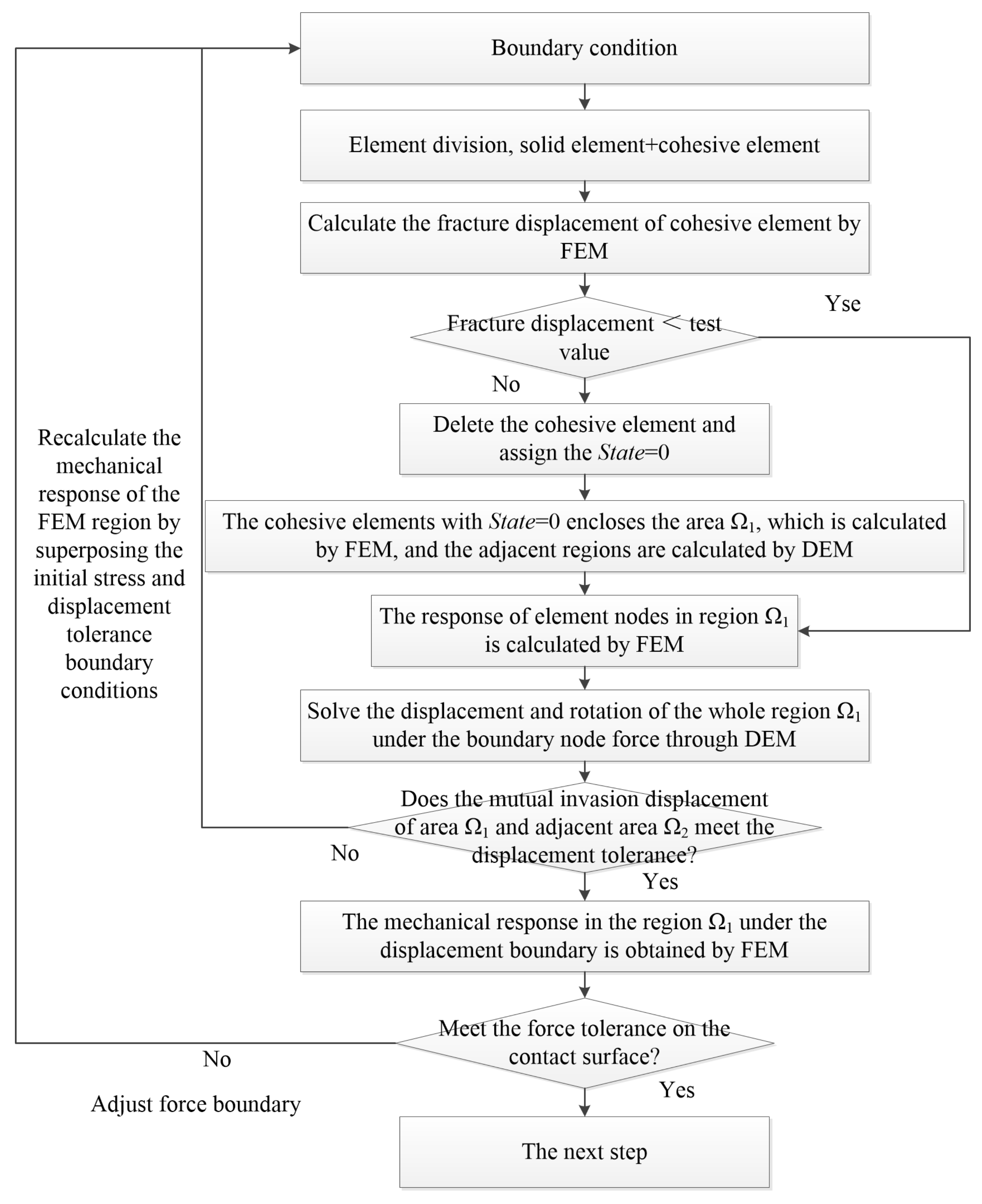
FDEM is the coupling simulation method of finite element (FEM) and discrete element (DEM). The main idea of this method is as follows:
- (1)
Firstly, the calculation area is divided into solid elements and cohesive elements, as shown in
Figure 5.
- (2)
The material parameters and boundary conditions are given to the numerical model. The node force and displacement of solid elements and cohesive elements under mining conditions are calculated by FEM. When the displacement of the cohesive element is greater than the displacement obtained from the experiment, the element is deleted and the variable state = 0 is assigned.
- (3)
Search the cohesive element with state = 0 in the whole numerical model, determine the enclosed area, and record it as Ωi. In the Ωi region, the FEM method is used to calculate the node force and displacement of each element in the region after the cohesive elements in the Ωi boundary are deleted (i.e., self-balancing calculation).
- (4)
The node force of finite elements on the interface between the region Ωi and the adjacent Ωi+1 region is applied to the discrete element nodes by sharing nodes. Under this condition, displacement S1 and rotation angle α1 of discrete element region Ωi can be calculated by DEM.
- (5)
Judge whether the “invasion displacement S1” on the interface between the area Ωi and the adjacent Ωi+1 area meets the displacement tolerance Stolerance obtained by the DEM method. If it is satisfied, further calculate the mechanical response in the FEM region Ωi, see step 6 for details. Otherwise, Stolerance is taken as the displacement boundary condition, the node force and displacement in the region Ωi are calculated by FEM.
- (6)
Assuming that the displacement of the contact point is continuous, the displacement boundary condition is applied to the adjacent Ωi+1 region according to the node displacement value of the boundary of Ωi region calculated by the DEM method, and the mechanical response of the internal element in Ωi region is solved by FEM.
In summary, the significance of the FDEM numerical method lies in the following aspects: (1) Identification of the boundary between DEM and FEM. (2) How the node force in the finite element region is transferred to the discrete element region? (3) How to realize displacement continuity in two adjacent finite element regions? FDEM coupling simulation process is shown in
Figure 6.
4.3. Numerical Calculation Results
The numerical simulation results of overburden fractures development and vertical stress distribution at different advance distances (
L) of Working Face 5105 are shown in
Figure 7.
It can be seen from
Figure 7a,b that when the working face was advanced from
L = 0 m to
L = 60 m, concentrated vertical stress was generated at 15 m in front of the coal wall of the working face. Before the direct roof and key stratum were completely broken, the maximum value of the advanced support pressure was about 27 MPa. After the roof was broken, the advance support pressure was reduced to 16 MPa. The mining fractures in the roof appeared 15~20 m ahead of the working face.
When the working face advanced to L = 120 m, the distance between the working face and the fault was 47 m. At this time, roof mudstone and siltstone were fractured, and periodic pressure occurred. The maximum pressure was about 24.8 MPa, which occurred 12 m in front of the coal wall. However, due to the low rock mechanical strength near the fault, the mining fractures in the roof appeared 35 m ahead of the working face.
When the working face advanced to L = 180 m, the working face was just near the fault. At this time, roof mudstone and siltstone were fractured synchronously, leading to a large area of collapse of the rock stratum, and the maximum advance pressure was about 30 MPa, which occurred 10~25 m in front of the coal wall. Similarly, the strength of rock mass near the fault was low, leading to mining-induced fractures of the roof occurring 25 m ahead of the working face.
When the working face advanced to L = 240 m, the distance between the working face and the fault was 24 m. At this time, the roof mudstone was partially collapsed, while the siltstone was generally intact. At the same time, the strength of rock mass near the fault was low, resulting in the accumulation of stress near the fault, and the formation of an advanced bearing pressure of up to 35 MPa at 30 m in front of the working face. The mining fractures of roof appeared 35 m ahead of the working face.
When the working face advanced to L = 300 m, 360 m, and 420 m, the working face would gradually move away from the fault. At this time, with the increase in roof suspension distance-periodic collapse, the maximum advanced support pressure was between 24 and 30 MPa, and the mining-induced fractures of the roof appeared 20~30 m ahead of the working face.
5. In Situ Tests of Pre-Grouting in Advanced Fractures
According to the results of numerical simulation and laboratory experiments, the grouting time can be determined. In addition, the grouting reinforcement layer and borehole layout are determined in combination with the mining conditions of the working face, and the effect was evaluated after the grouting was completed.
- (1)
Grouting reinforcement layer
The top-coal caving mining method was adopted in the 5105 working face. The in situ test results showed that the root cause of the roof fall is a vicious circle process: the mining of extra-thick coal seams produced huge ground pressure, which made the coal wall caving, thus the roof lost the support and roof fall occurred, which made it difficult for the hydraulic support to connect to the roof. As a result, the coal wall bears more ground pressure, and the phenomenon of wall spalling and roof fall further occurred; forming a vicious circle process. The key to solving the above roof disasters is to improve the bearing capacity of coal seams and ensure that the coal wall of the working face provides effective support for the roof. Therefore, the main layer of grouting reinforcement is the coal seam.
- (2)
Grouting drilling layout
The two rows of drilling holes were arranged in a “quincunx hole” arrangement. The inclined length of 5105 working face is 177 m (
Figure 4), so the length of grouting holes in
Figure 8 is determined as 85 m. The dip angle of the lower row of boreholes was set to 3°, and the upper row was set to 8°. According to the drill pipe size of the coal mine drilling machine, the boreholes diameter is 75 mm. In addition, the laboratory test and in situ grouting test show that in the mining coal seam, the grouting pressure and the slurry diffusion radius have the following relationship:
where
y is the grouting pressure, MPa;
x is the slurry diffusion radius, mm. When the grouting pressure is 7 MPa, the slurry diffusion radius is 6.7 m. Therefore, the spacing of grouting holes is designed as 10 m. A scheme of drilling wells for injection of a cement slurry into a coal seam is shown in
Figure 9. The grouting pressure is in the range of 7~7.5 MPa. When the pressure in the hole entrance is 7 MPa and lasts for 30 min, the grouting can be stopped.
- (3)
Timing of grouting
Reasonable grouting time is crucial to ensure the grouting effect.
The timing of grouting was determined by comprehensively considering the following three aspects:
- (a)
Laboratory test results. The compressive strength of the grouting coal on day 7 of consolidation time reaches 29,269 N. This strength can not only meet the requirements of consolidation of broken coal, but also not affect the practice of top-coal caving due to too high strength.
- (b)
The advance speed of 5105 working face is 3~4 m/d, and pre-grouting was carried out 21~28 m ahead of the working face (i.e., the consolidation time is 7d) to make the grouting material completely solidified.
- (c)
The numerical simulation results (
Section 4) showed that the mining roof fractures appear 20~30 m ahead of the working face.
Considering the above data, grouting was carried out when the distance between the drilling hole and the working face was 20~30 m.
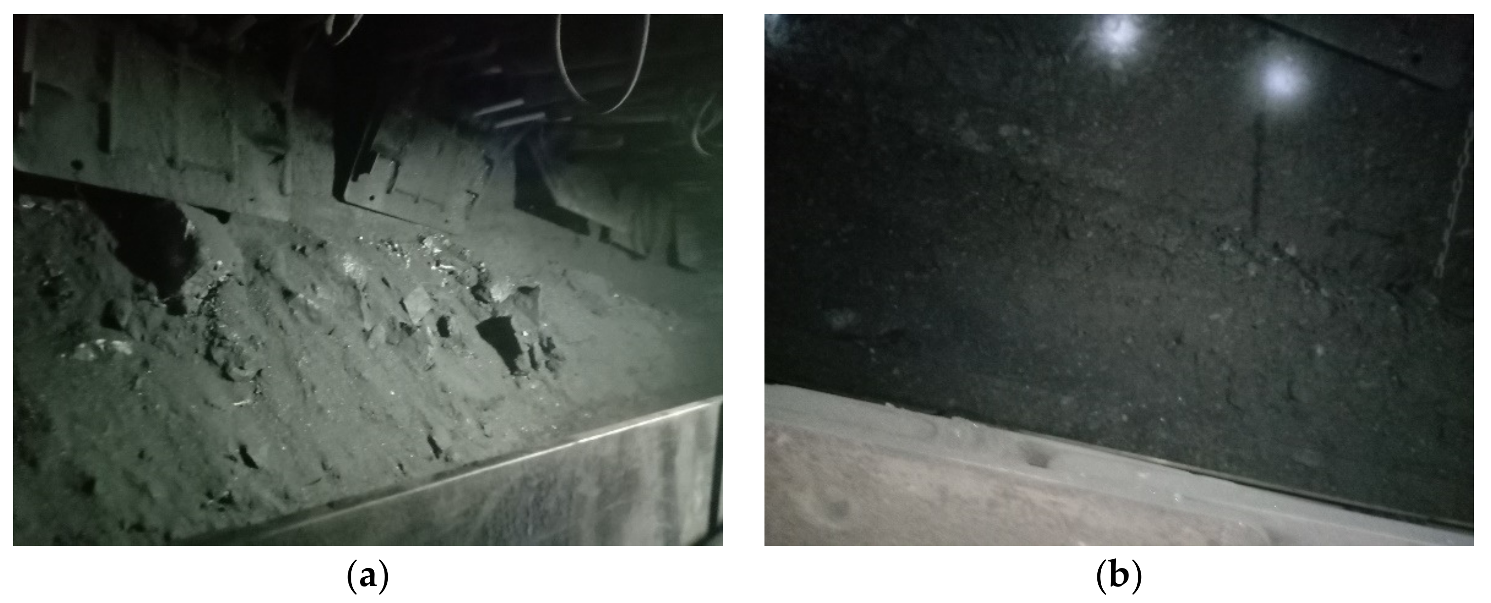
The photos before and after the in situ grouting test are shown in
Figure 9a,b, respectively. It can be seen that a large number of broken coal appear in front of the hydraulic support, which means that the phenomenon of roof fall is serious. After grouting, the compressive strength of the coal seam is greatly increased, and roof fall rarely occurs. This means that the advanced fractures location predicted by the progressive failure constitutive equations and the FDEM numerical method is accurate, which can effectively guide the pre-grouting practice and reduce the impact of roof fall disasters.
6. Conclusions
- (1)
The compressive strength of the No. 5 coal in Yushupo Coal Mine is 3.19 MPa, and the compressive strength of the grouted coal is 6.82 MPa, 14.91 MPa, and 16.93 MPa after solidification for 3d, 7d, and 15d, respectively. The strength of grouted coal is 4.67 times that of coal 7 days after solidification.
- (2)
The constitutive equation of progressive failure process can effectively describe the development law of advanced fractures in the roof under the mining conditions of extra-thick coal seams. The numerical results show that the advanced support pressure of 5105 working face is between 24 and 35 MPa, and the advanced fractures in the roof appear at 15~35 m.
- (3)
According to the simulation results and engineering conditions, two rows of grouting boreholes are set in the coal seam. The distance between adjacent boreholes is 10 m, and the length of boreholes is 85 m. Grouting is carried out at 20~30 m in front of the working face. The in situ test shows that the above grouting method can effectively prevent roof falling disasters.
Author Contributions
Conceptualization, G.G.; methodology, H.L.; software, H.L.; validation, G.G.; formal analysis, H.L.; investigation, G.G.; resources, G.G.; data curation, G.G.; writing—original draft preparation, H.L.; writing—review and editing, H.L.; visualization, H.L.; supervision, G.G.; project administration, G.G.; funding acquisition, G.G. All authors have read and agreed to the published version of the manuscript.
Funding
This work was supported by the National Natural Science Foundation of China (No. 42102310), Fundamental Research Program of Shanxi Province (No. 20210302123106), and Open Fund Project of Shaanxi Key Laboratory of Prevention and Control Technology for Coal Mine Water Hazard (No. 2021SKMS03).
Data Availability Statement
No new data were created.
Conflicts of Interest
The authors declare no conflict of interest.
References
- Yang, Q.; Zhang, L.; Zhang, J.; Zou, S. System simulation and policy optimization of China’s coal production capacity deviation in terms of the economy, environment, and energy security. Resour. Policy 2021, 74, 102314. [Google Scholar] [CrossRef]
- Peng, C.; Chen, H.; Lin, C.; Guo, S.; Yang, Z.; Chen, K. A framework for evaluating energy security in China: Empirical analysis of forecasting and assessment based on energy consumption. Energy 2021, 234, 121314. [Google Scholar] [CrossRef]
- He, W.; He, F.; Zhao, Y. Field and simulation study of the rational coal pillar width in extra-thick coal seams. Energy Sci. Eng. 2019, 8, 627–646. [Google Scholar] [CrossRef]
- Yu, B. Behaviors of overlying strata in extra-thick coal seams using top-coal caving method. J. Rock Mech. Geotech. Eng. 2016, 8, 238–247. [Google Scholar] [CrossRef]
- Tian, S.; Xu, X.; Li, Z. Disaster-inducing mechanism in a roadway roof near the driving face and its safety-control criteria. Saf. Sci. 2019, 115, 208–214. [Google Scholar] [CrossRef]
- Gu, S.; Jiang, B.; Wang, G.; Dai, H.; Zhang, M. Occurrence Mechanism of Roof-Fall Accidents in Large-Section Coal Seam Roadways and Related Support Design for Bayangaole Coal Mine, China. Adv. Civ. Eng. 2018, 2018, 6831731. [Google Scholar] [CrossRef]
- Vu, T.T. Solutions to prevent face spall and roof falling in fully mechanized longwall at underground mines, Vietnam. Min. Miner. Deposits 2022, 16, 127–134. [Google Scholar] [CrossRef]
- Zingano, A.C.; Andrade, M. Analysis of Roof Failure at the Intersections on a Coal Mining. J. Miner. Mater. Charact. Eng. 2021, 9, 499–511. [Google Scholar] [CrossRef]
- Sun, Y.; Li, G.; Zhang, N.; Chang, Q.; Xu, J.; Zhang, J. Development of ensemble learning models to evaluate the strength of coal-grout materials. Int. J. Min. Sci. Technol. 2020, 31, 153–162. [Google Scholar] [CrossRef]
- Rajwa, S.; Janoszek, T.; Prusek, S. Influence of canopy ratio of powered roof support on longwall working stability—A case study. Int. J. Min. Sci. Technol. 2019, 29, 591–598. [Google Scholar] [CrossRef]
- Cheng, Q.; Shi, Y.; Zuo, L. Numerical Simulation and Analysis of Surface and Surrounding Rock Failure in Deep High-Dip Coal Seam Mining. Geotech. Geol. Eng. 2019, 37, 4285–4299. [Google Scholar] [CrossRef]
- Liu, W.-R. Experimental and Numerical Study of Rock Stratum Movement Characteristics in Longwall Mining. Shock. Vib. 2019, 2019, 5041536. [Google Scholar] [CrossRef]
- Li, Q.; Wu, G.; Kong, D. Study on Stability of Stope Surrounding Rock under Repeated Mining in Close-Distance Coal Seams. Geofluids 2022, 2022, 9630942. [Google Scholar] [CrossRef]
- Song, G.; Chugh, Y.P.; Wang, J. A numerical modelling study of longwall face stability in mining thick coal seams in China. Int. J. Min. Miner. Eng. 2017, 8, 35–55. [Google Scholar] [CrossRef]
- Jiao, H.; Yang, W.; Chen, X.; Yang, L.; Li, Z. High Mining Face Flexible Reinforcement to Prevent Coal Wall Spalling by Cuttable Aluminum–Plastic Pipe Pre-Grouting. Energies 2022, 15, 3233. [Google Scholar] [CrossRef]
- Kong, D.Z.; Cheng, Z.B.; Zheng, S.S. Study on the failure mechanism and stability control measures in a large-cutting-height coal mining face with a deep-buried seam. Bull. Eng. Geol. Environ. 2019, 78, 6143–6157. [Google Scholar] [CrossRef]
- Wang, J.; Zhang, Q.; Zhang, J.; Liu, H.; Zhu, G.; Wang, Y. Study on the controller factors associated with roof falling and ribs spalling in deep mine with great mining height and compound roof. Eng. Fail. Anal. 2021, 129, 105723. [Google Scholar] [CrossRef]
- Liu, H.; Chen, Y.; Han, Z.; Liu, Q.; Luo, Z.; Cheng, W.; Zhang, H.; Qiu, S.; Wang, H. Coal Wall Spalling Mechanism and Grouting Reinforcement Technology of Large Mining Height Working Face. Sensors 2022, 22, 8675. [Google Scholar] [CrossRef]
- Mondal, D.; Roy, P. Fractal and seismic b-value study during dynamic roof displacements (roof fall and surface blasting) for enhancing safety in the longwall coal mines. Eng. Geol. 2019, 253, 184–204. [Google Scholar] [CrossRef]
- Ghosh, G.K.; Sivakumar, C. Application of underground microseismic monitoring for ground failure and secure longwall coal mining operation: A case study in an Indian mine. J. Appl. Geophys. 2018, 150, 21–39. [Google Scholar] [CrossRef]
- Cai, M.; Hou, P.; Zhang, X.; Feng, X. Post-peak Stress–Strain curves of brittle hard rocks under axial-strain-controlled loading. Int. J. Rock Mech. Min. Sci. 2021, 147, 104921. [Google Scholar] [CrossRef]
- Hou, P.Y.; Cai, M.; Zhang, X.W.; Feng, X.T. Post-peak Stress–Strain Curves of Brittle Rocks Under Axial-and Lateral-Strain-Controlled Loadings. Rock Mech. Rock Eng. 2022, 55, 855–884. [Google Scholar] [CrossRef]
- Sun, Y.; Zuo, J.; Karakus, M.; Wang, J. Investigation of movement and damage of integral overburden during shallow coal seam mining. Int. J. Rock Mech. Min. Sci. 2019, 117, 63–75. [Google Scholar] [CrossRef]
- Li, H.; Liang, W.; Jiang, Y.; Wu, P.; Wu, J.; He, W. Numerical Study on the Field-Scale Criterion of Hydraulic Fracture Crossing the Interface Between Roof and Broken Low-Permeability Coal. Rock Mech. Rock Eng. 2021, 54, 4543–4567. [Google Scholar] [CrossRef]
- Park, K.; Paulino, G.H.; Roesler, J.R. Virtual Internal Pair-Bond Model for Quasi-Brittle Materials. J. Eng. Mech. 2008, 134, 856–866. [Google Scholar] [CrossRef]
- Li, H.; Bai, H.B.; Ma, L.Q.; Kang, Z.Q.; Li, Z.Y.; Miao, X.C.; Wu, P.F.; Wei, J. Research on the evolution law of water flowing fractures in the Jurassic and Carboniferous coal seams based on FDEM simulation. J. China Coal Soc. 2022, 47, 4443–4454. [Google Scholar]
- Guo, G.; Wang, Z.; Qu, S.; Li, H.; Zhou, Y.; Lyu, H.; He, Y. Study on Explicit–Implicit Simulation and In-Situ Measurement of Floor Failure Law in Extra-Thick Coal Seams. Minerals 2022, 12, 1511. [Google Scholar] [CrossRef]
| Disclaimer/Publisher’s Note: The statements, opinions and data contained in all publications are solely those of the individual author(s) and contributor(s) and not of MDPI and/or the editor(s). MDPI and/or the editor(s) disclaim responsibility for any injury to people or property resulting from any ideas, methods, instructions or products referred to in the content. |
© 2023 by the authors. Licensee MDPI, Basel, Switzerland. This article is an open access article distributed under the terms and conditions of the Creative Commons Attribution (CC BY) license (https://creativecommons.org/licenses/by/4.0/).


