
Study on Water Intake Characteristics and Influencing Parameters of Drinking Water Emergency Extraction Vehicle


Abstract
:1. Introduction
2. Materials and Methods
- (1)
- The mass conservation equation between air and adsorbent is as follows:
- (2)
- The mass transfer equation of adsorbent side is expressed as:
- (3)
- The energy conservation equation between the air and the adsorbent is:
- (4)
- The heat transfer equation of adsorbent side can be expressed as:
3. Simulation Analysis of the Parameters Influencing the Water Extraction Characteristics of Emergency Drinking Water Extraction Vehicles
3.1. Analysis of Rotor Moisture Absorption/Desorption Performance Parameters
3.2. Analysis of the Influence of Runner Structure Parameters on Water Intake Performance
3.2.1. Thickness
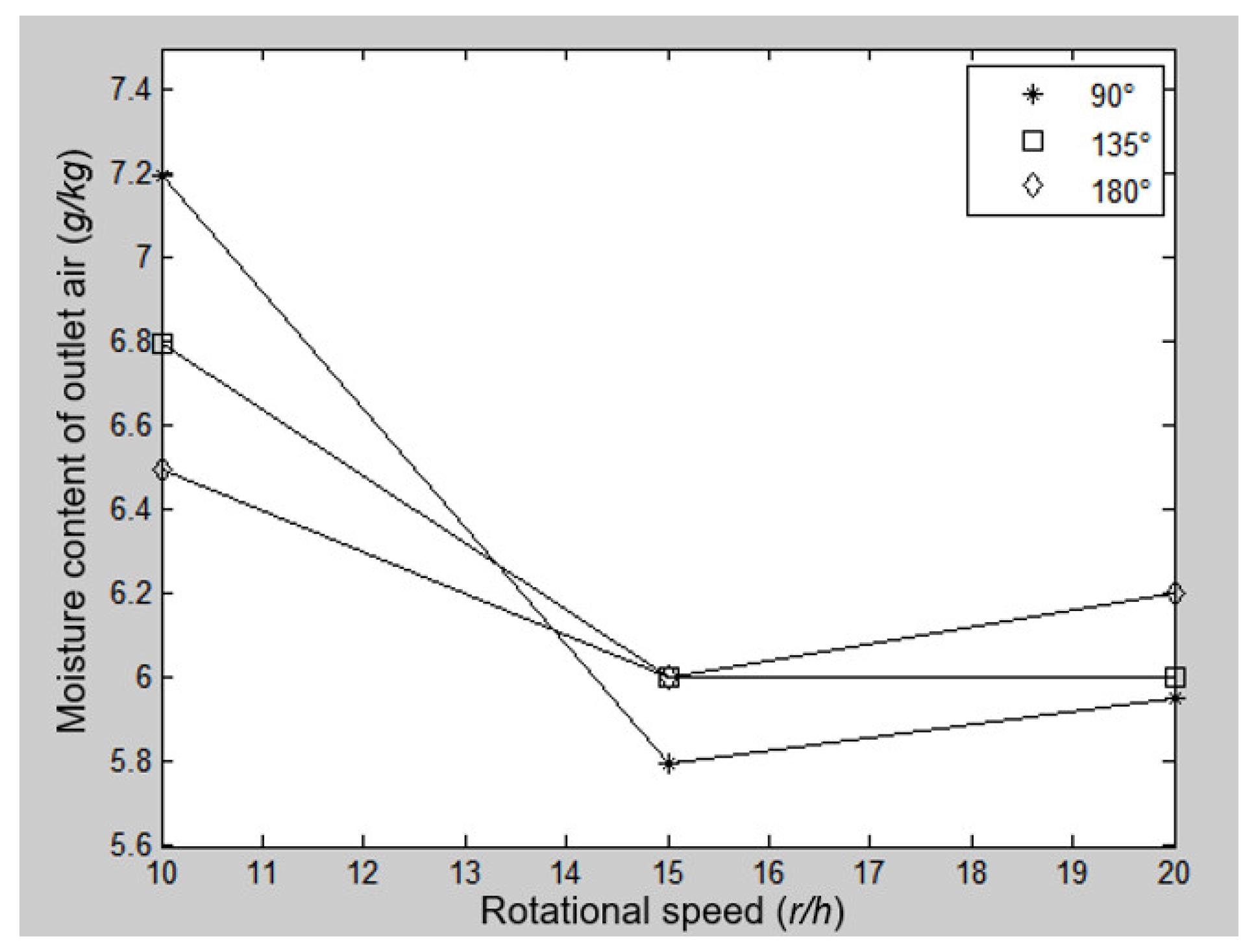
3.2.2. Speed
3.2.3. Regeneration Angle
3.3. Analysis of Influence of Air Parameters on Water Intake Characteristics
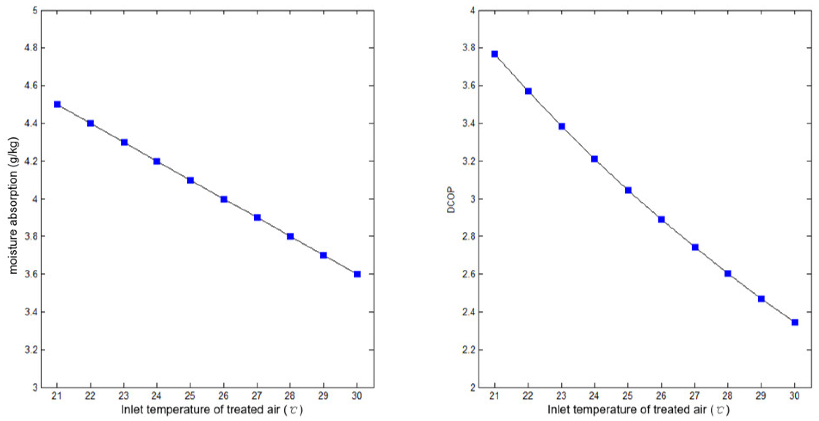
3.3.1. Handle Air Inlet Temperature
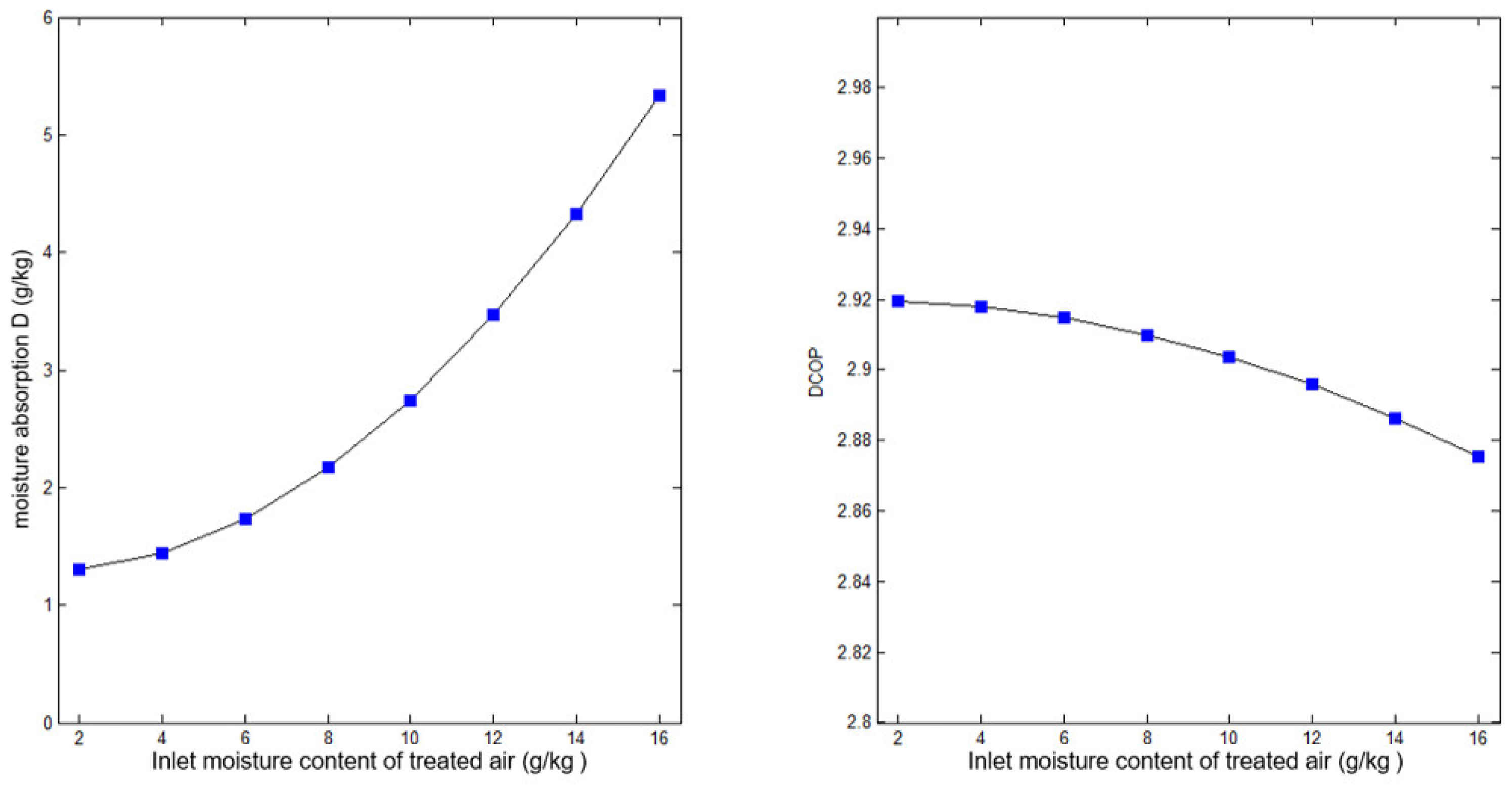
3.3.2. The Moisture Content of the Air Inlet
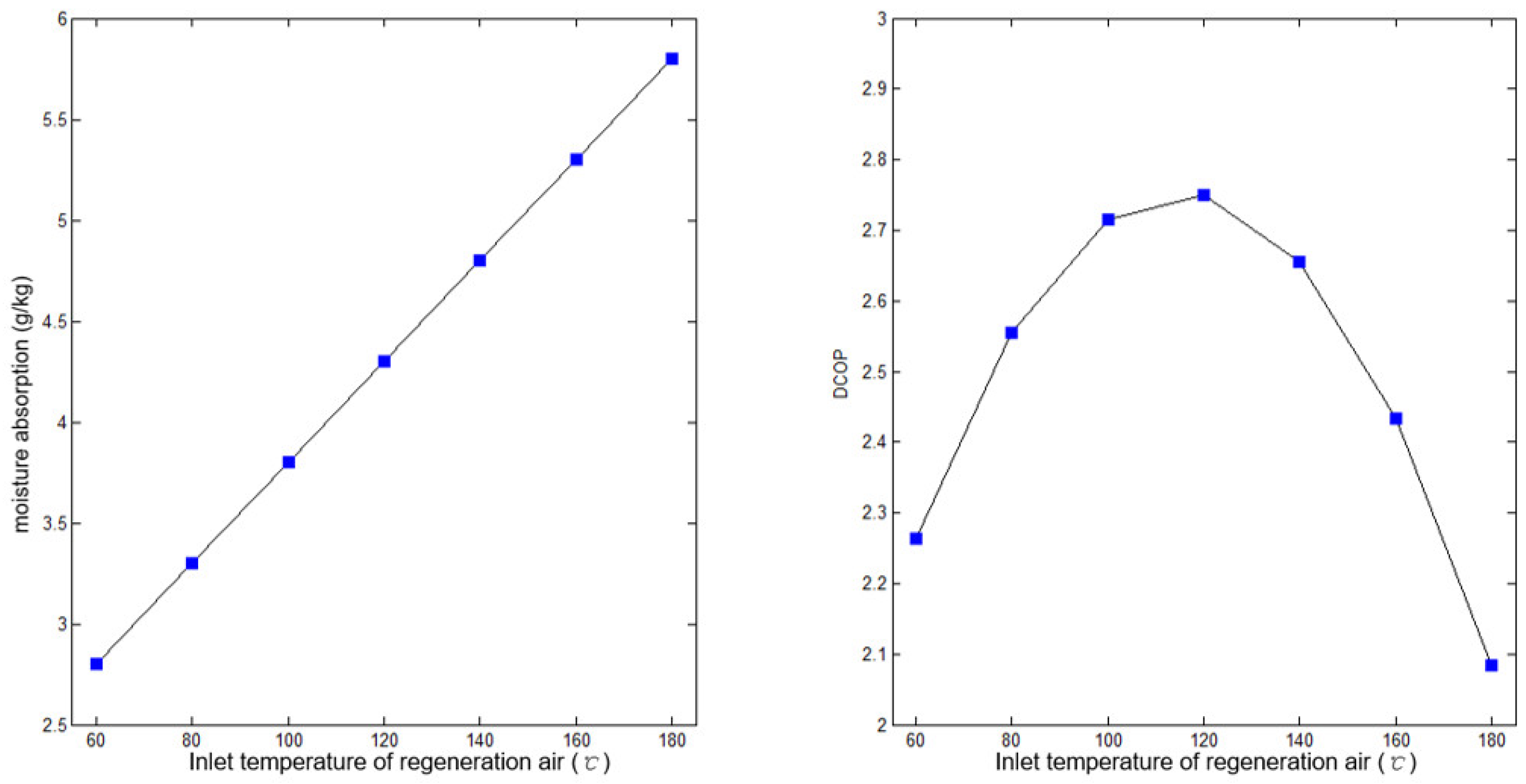
3.3.3. Inlet Temperature of Regenerated Air
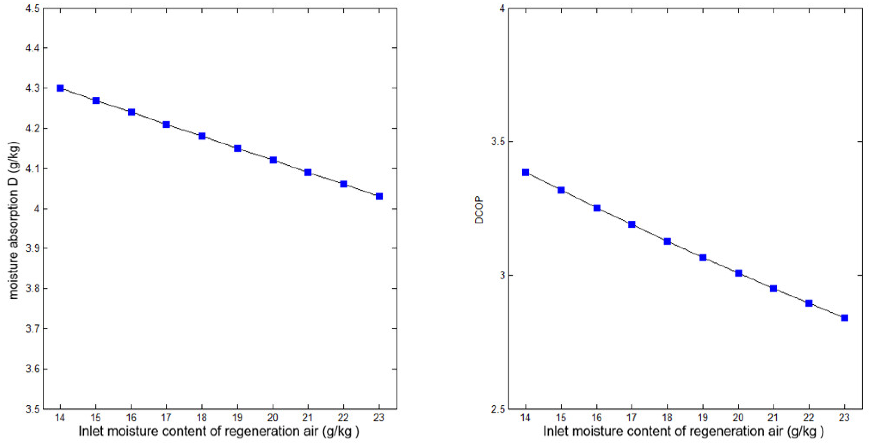
3.3.4. Moisture Content of Regenerated Air Inlet
4. Test and Verification of Water Intake Characteristics of Emergency Drinking Water Extraction Vehicle
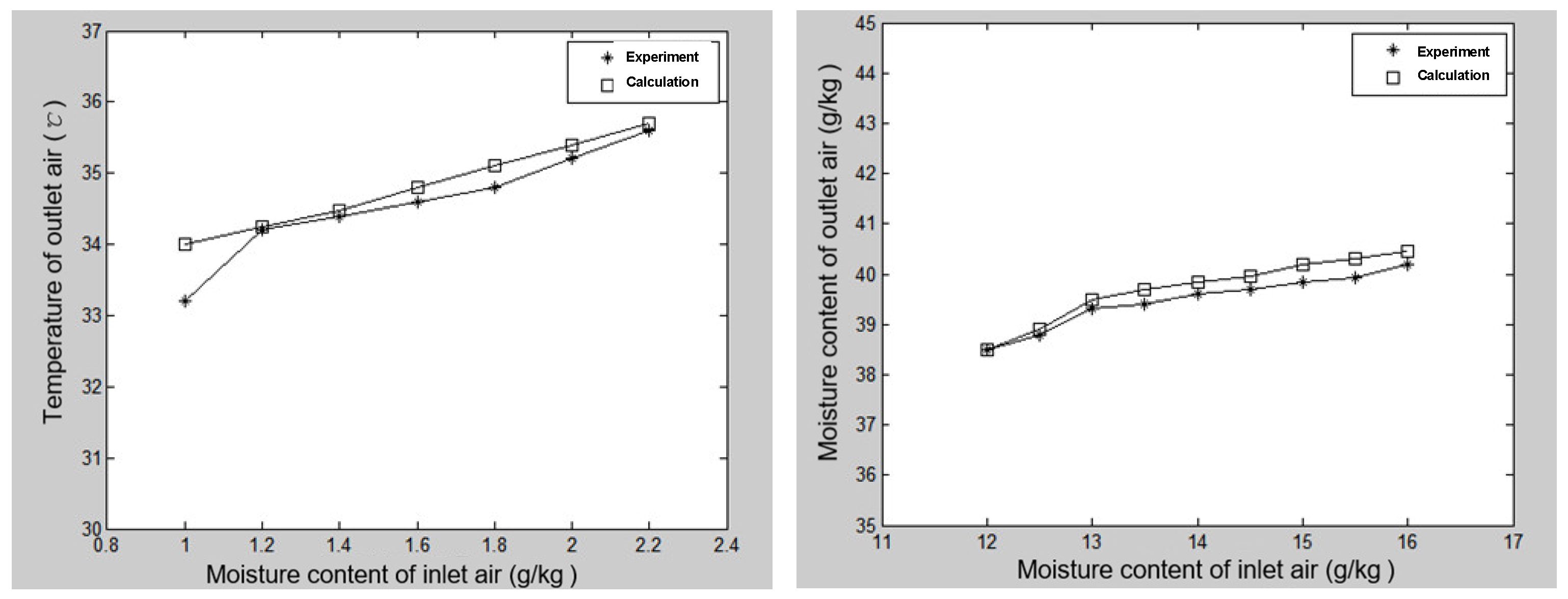
4.1. Comparison of Moisture Content of Treated Air Outlet
4.2. Comparison of Outlet Temperature of Treated Air
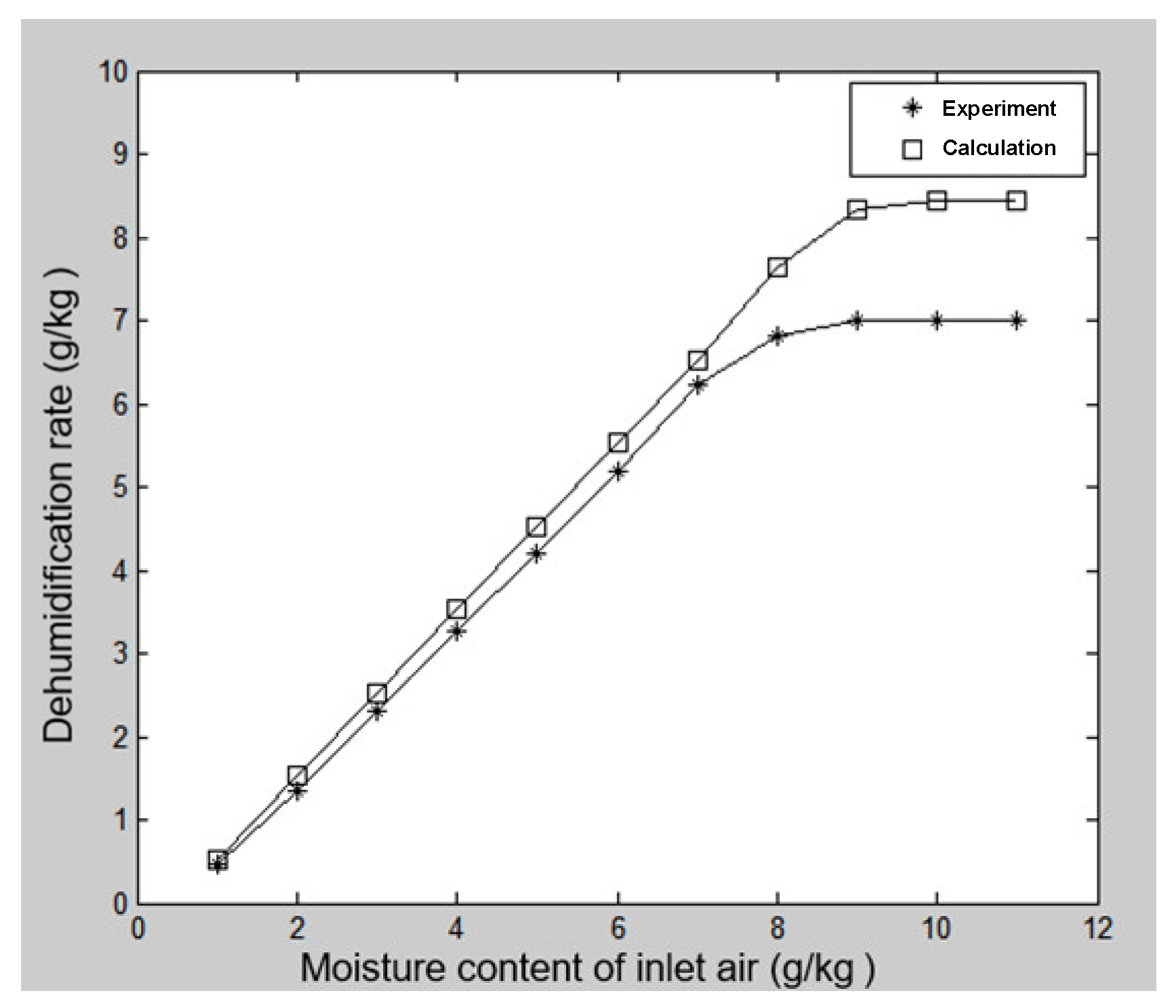
4.3. Comparison of Water Intake
5. Discussion
- Increasing the thickness of the runner is beneficial to improving its hygroscopicity/desorption capacity, and the thickness of the runner determines the optimal speed and regeneration angle;
- The temperature of regenerated air has an important effect on the desorption efficiency and the DCOP, and the humidity of the regenerated air has little effect on the wettability of the runner;
- The moisture absorption D and DCOP of the runner are inversely proportional to the temperature of the treated air and directly proportional to the humidity;
- The system design and the control of rotor parameters and air parameters can effectively increase water extraction.
6. Conclusions
- (1)
- The study of the partition ratio of the processing area and the regeneration area of the rotor. If the ratio of the processing area is too large, the moisture adsorbed by the absorbent cannot be fully carried away by the regeneration air. If the ratio of the processing area is too small, the moisture adsorbed by the absorbent is not enough to become saturated wet air, both of which reduce the utilization rate of the rotor.
- (2)
- Regeneration heating temperature determination. If the regeneration temperature is too high, it will lead to the increased energy consumption of the entire system; if the regeneration temperature is too low, this will lead to desorption not being complete. The regeneration temperature is determined by and directly related to the division of the rotor area, the moisture absorption material selection, etc., and any change in the regeneration temperature will need to change correspondingly.
Author Contributions
Funding
Data Availability Statement
Acknowledgments
Conflicts of Interest
References
- Biswas, A.K.; Tortajada, C. Water crisis and water wars: Myths and realities. Int. J. Water Resour. Dev. 2019, 35, 727–731. [Google Scholar] [CrossRef]
- Salehi, A.A.; Ghannadi-Maragheh, M.; Torab-Mostaedi, M.; Torkaman, R.; Asadollahzadeh, M. A review on the water-energy nexus for drinking water production from humid air. Renew. Sustain. Energy Rev. 2020, 120, 109627. [Google Scholar] [CrossRef]
- Tu, R.; Hwang, Y. Reviews of atmospheric water harvesting technologies. Energy 2020, 201, 117630. [Google Scholar] [CrossRef]
- Patel, J.; Patel, K.; Mudgal, A.; Panchal, H.; Sadasivuni, K.K. Experimental investigations of atmospheric water extraction device under different climatic conditions. Sustain. Energy Technol. Assess. 2020, 38, 100677. [Google Scholar] [CrossRef]
- Kandeal, A.W.; Joseph, A.; Elsharkawy, M.; Elkadeem, M.R.; Hamada, M.A.; Khalil, A.; Moustapha, M.E.; Sharshir, S.W. Research progress on recent technologies of water harvesting from atmospheric air: A detailed review. Sustain. Energy Technol. Assess. 2022, 52, 102000. [Google Scholar] [CrossRef]
- Shafeian, N.; Ranjbar, A.A.; Gorji, T.B. Progress in atmospheric water generation systems: A review. Renew. Sustain. Energy Rev. 2022, 161, 112325. [Google Scholar] [CrossRef]
- Raveesh, G.; Goyal, R.; Tyagi, S.K. Advances in atmospheric water generation technologies. Energy Convers. Manag. 2021, 239, 114226. [Google Scholar] [CrossRef]
- Toribio, F.; Bellat, J.P.; Nguyen, P.H.; Dupont, M. Adsorption of water vapor by poly (styrenesulfonic acid), sodium salt: Isothermal and isobaric adsorption equilibria. J. Colloid Interface Sci. 2004, 280, 315–321. [Google Scholar] [CrossRef] [PubMed]
- Seo, Y.K.; Yoon, J.W.; Lee, J.S.; Hwang, Y.K.; Jun, C.H.; Chang, J.S.; Wuttke, S.; Bazin, P.; Vimont, A.; Daturi, M.; et al. Energy-efficient dehumidification over hierachically porous metal–organic frameworks as advanced water adsorbents. Adv. Mater. 2012, 24, 806–810. [Google Scholar] [CrossRef] [PubMed]
- Tao, P.; Liao, B.; Tan, Y. A primary study on the water absorbing/releasing performance of molecular sieve desiccant. Procedia Eng. 2012, 27, 781–786. [Google Scholar] [CrossRef]
- Hao, X.; Geng, S.; Yuan, L.; Luo, B. Study of composite scheme of absorption/desorption method and condensation method for extracting water from air. Procedia Eng. 2017, 205, 2069–2075. [Google Scholar] [CrossRef]
- Zhang, T.; Liu, X.H.; Zhang, L.; Jiang, Y. Match properties of heat transfer and coupled heat and mass transfer processes in air-conditioning system. Energy Convers. Manag. 2012, 59, 103–113. [Google Scholar] [CrossRef]
- Ge, T.S.; Li, Y.; Wang, R.Z.; Dai, Y.J. A review of the mathematical models for predicting rotary desiccant wheel. Renew. Sustain. Energy Rev. 2008, 12, 1485–1528. [Google Scholar] [CrossRef]
- Zhang, X.J.; Dai, Y.J.; Wang, R.Z. A simulation study of heat and mass transfer in a honeycombed rotary desiccant dehumidifier. Appl. Therm. Eng. 2003, 23, 989–1003. [Google Scholar] [CrossRef]
- Hao, H.; Song, X.Y.; Xin, P. Study on the adsorption and purification performance of runner with different staged regeneration modes. In IOP Conference Series: Materials Science and Engineering; IOP Publishing: Brașov, Romania, 2020; Volume 789, p. 012025. [Google Scholar]
- Eslami, M.; Tajeddini, F.; Etaati, N. Thermal analysis and optimization of a system for water harvesting from humid air using thermoelectric coolers. Energy Convers. Manag. 2018, 174, 417–429. [Google Scholar] [CrossRef]
- Chen, Z.; Song, S.; Ma, B.; Li, Y.; Shao, Y.; Shi, J.; Liu, M.; Jin, H.; Jing, D. Recent progress on sorption/desorption-based atmospheric water harvesting powered by solar energy. Sol. Energy Mater. Sol. Cells 2021, 230, 111233. [Google Scholar] [CrossRef]
- Kim, H.; Yang, S.; Rao, S.R.; Narayanan, S.; Kapustin, E.A.; Furukawa, H.; Umans, A.S.; Yaghi, O.M.; Wang, E.N. Water harvesting from air with metal-organic frameworks powered by natural sunlight. Science 2017, 356, 430–434. [Google Scholar] [CrossRef] [PubMed]
- Abdelgaied, M.; Kabeel, A.E.; Zakaria, Y. Performance improvement of desiccant air conditioner coupled with humidification-dehumidification desalination unit using solar reheating of regeneration air. Energy Convers. Manag. 2019, 198, 111808. [Google Scholar] [CrossRef]
- Ge, T.S.; Dai, Y.J.; Wang, R.Z. Review on solar powered rotary desiccant wheel cooling system. Renew. Sustain. Energy Rev. 2014, 39, 476–497. [Google Scholar] [CrossRef]
- Pang, Y.F. The theoretical analysis and experimental research on the optimal condition of semiconductor refrigeration. In IOP Conference Series: Earth and Environmental Science; IOP Publishing: Beijing, China, 2016; Volume 40, p. 012013. [Google Scholar]
- Wei, X.; Chai, Z.; Fang, L.; Luo, M.; Gou, M.; Zhen, X. Experiment of Solar Semiconductor Condensing Wall Water Intake System Based on Big Data. In Journal of Physics: Conference Series; IOP Publishing: Hubei, China, 2021; Volume 2138, p. 012022. [Google Scholar]


| Name | Numerical Value |
|---|---|
| Regeneration air inlet temperature θreg (°C) | 130 |
| Treated air inlet temperature θads (°C) | 25 |
| Treated air inlet humidity øads (%) | 29.14 |
| Reclaimed air flow rate Vreg (m·s−1) | 1.5 |
| Treatment air flow rate Vreg (m·s−1) | 2.0 |
| Specific constant pressure heat capacity of molecular sieve cpd (J·kg−1·K−1) | 0.92 × 10³ |
| Specific heat at constant pressure of the base material cpm (J·kg−1·K−1) | 0.9 × 10³ |
| Line mass ρId of desiccant on in a single channel ρId (kg ·m−1) | 5 × 10⁻³ |
| Line mass ρIm (kg·m−1) of the base material in a single channel ρIm (kg·m−1) | 3 × 10⁻³ |
| Channel half-height h (m) | 1.5 × 10⁻³ |
| Channel half-width b (m) | 1.5 × 10⁻³ |
| Aspect ratio γ = 2h/b | 2 |
| Nusser number Nuz | 2.45 |
| Sherwood number Shz | 2.45 |
| Runner thickness δ (m) | 0.2 |
| Rotor radius r (m) | 0.6 |
| Rotational speed n (r·min−1) | 0.25 |
| Thermal conductivity of dry air at 100 °C λ (w·m−1·K−1) | 3.21 × 10⁻² |
| Constant pressure specific heat of dry air at 100 °C cpm (J·kg−1·K−1) | 1.01 × 10³ |
| Constant-pressure specific heat of dry saturated water vapor at 100 °C cpv (J·kg−1·K−1) | 2.03 × 10³ |
| Constant pressure specific heat of saturated water at 60 °C cpl (J·kg−1·K−1) | 4.18 × 10³ |
| Latent heat of evaporation of saturated water at 60 °C Lv (J·kg−1) | 2.36 × 10⁶ |
| Name (Unit) | Numerical Value |
|---|---|
| Runner diameter (m) | 1.2 |
| Rotation speed (r/h) | 15 |
| Adsorbent thickness (cm) | 20 |
| Regenerative angle (°) | 90 |
| Regeneration temperature (°C) | 130 |
| Processing air volume (m3/h) | 12,000 |
| Renewable wind volume (m3/h) | 4000 |
Disclaimer/Publisher’s Note: The statements, opinions and data contained in all publications are solely those of the individual author(s) and contributor(s) and not of MDPI and/or the editor(s). MDPI and/or the editor(s) disclaim responsibility for any injury to people or property resulting from any ideas, methods, instructions or products referred to in the content. |
© 2023 by the authors. Licensee MDPI, Basel, Switzerland. This article is an open access article distributed under the terms and conditions of the Creative Commons Attribution (CC BY) license (https://creativecommons.org/licenses/by/4.0/).
Share and Cite
Hou, Y.; Li, G.; Bao, H.; Zhao, R.; Zhang, W. Study on Water Intake Characteristics and Influencing Parameters of Drinking Water Emergency Extraction Vehicle. Processes 2023, 11, 555. https://doi.org/10.3390/pr11020555
Hou Y, Li G, Bao H, Zhao R, Zhang W. Study on Water Intake Characteristics and Influencing Parameters of Drinking Water Emergency Extraction Vehicle. Processes. 2023; 11(2):555. https://doi.org/10.3390/pr11020555
Chicago/Turabian StyleHou, Yaoqing, Gangyan Li, Hanwei Bao, Ran Zhao, and Wen Zhang. 2023. "Study on Water Intake Characteristics and Influencing Parameters of Drinking Water Emergency Extraction Vehicle" Processes 11, no. 2: 555. https://doi.org/10.3390/pr11020555
APA StyleHou, Y., Li, G., Bao, H., Zhao, R., & Zhang, W. (2023). Study on Water Intake Characteristics and Influencing Parameters of Drinking Water Emergency Extraction Vehicle. Processes, 11(2), 555. https://doi.org/10.3390/pr11020555