Abstract
Object recognition and tracking is a challenge for underwater vehicles. Traditional algorithm requires a clear feature definition, which suffers from uncertainty as the variation of occlusion, illumination, season and viewpoints. A deep learning approach requires a large amount of training data, which suffers from the computation. The proposed method is to avoid the above drawbacks. The Siamese Region Proposal Network tracking algorithm using two weights sharing is applied to track the target in motion. The key point to overcome is the one-shot detection task when the object is unidentified. Various complex and uncertain environment scenarios are applied to evaluate the proposed system via the deep learning model’s predictions metrics (accuracy, precision, recall, P-R curve, F1 score). The tracking rate based on Siamese Region Proposal Network Algorithm is up to 180 FPS.
1. Introduction
In recent years, there has been an increasing interest in Autonomous Underwater Vehicles (AUVs) (e.g., subsea inspection, maintenance, and repair operations [1], resource exploration [2], species abundance investigation [3], and military science [4,5]). Recent developments in the field of Artificial intelligence (AI) have led to a renewed interest in underwater unmanned vehicles.
One of the most essential current discussions in AUV is target tracking. There are three basic approaches currently adopted by research on object tracking. One is the target appearance features approach, kernelized correlation filters approach, and the other is deep learning approach. The former two are non-AI approaches, which is slow and suffer from lack of sufficient background information in comparison to deep learning approach.
A Faster R-CNN and kernelized correlation filter (KCF) tracking algorithm was proposed [6] to achieve the detection and counting small objects for underwater robot to catch seafood. Their study showed the proposed method can recognize and catch seafood in real time.
There are four factors affecting the performance of target tracking. These are (1) low and non-uniform illumination causing image blurred and low color contrast; (2) various viewpoint leading a morphological change of target in image; (3) occlusion from underwater creature; and (4) scale variation.
An adaptive approach has been proposed to select the Walsh–Hadamard kernels for the efficient extraction of features under the influence of the underwater optical dynamics [7]. The performance demonstrated the robustness to the hazy and degraded, partially occluded, and camouflaged uncertainties.
There are generally two approaches for target tracking of mobile robots; these are filter based and learning based. The particle-filter based on the track-before-detect scheme was proposed for underwater targets detection and tracking with low signal-to-noise ratios [8]. The results showed the system at low signal-to-noise having comparable performance at higher signal-to-noise. Their approach is tempting to focus on characterizing objects of interest (positive samples). However, background information should be given more consideration (negative samples).
However, the visual tracking of objects using kernelized correlation filter suffer from presence of multi-scale. Therefore, GMM is adopted to re-detect and correct the tracking model in kernelized correlation filter tracking process [9]. The result demonstrates a better tracking performance under scale variation.
An underwater image restoration and Kernelized Correlation Filters (KCF) was proposed for underwater robots to handle the conflict between tracking speed and accuracy [10]. The results achieved a better tracking accuracy and speed for different underwater objects.
In recent years, there has been an increasing interest in learning-based target tracking. A basic tracking algorithm with a fully-convolutional Siamese network was proposed for the training on the offline video dataset for object detection [11]. The concept of offline pre-training and not updating online has the advantage that the target won’t be contaminated and the detection area is large enough to not be affected by slight errors.
A Fully-Convolutional Siamese Networks was proposed for a monocular mobile robot tracking system [12]. The Siamese convolution network acted as the tracker to lock the target and followed by adopting the bearing conversion algorithm and speed conversion algorithm fort following the target. The experiment shows real-time target following at variable speeds according to the forward speed of the tracking target with safety distance even though having occlusion.
A Siam-FC autoencoder method is established for the change detection of unmanned aerial vehicle’s cameras [13]. The results show the number of labeled samples can be reduced with less training data.
However, far too little attention has been paid to the low-cost monocular vision based on deep learning for underwater object tracking. Most studies in object tracking, where the testing was conducted using offline video datasets. So far, those methods have only been applied to ground and aerial vehicles. So far, however, there has been little discussion about the underwater object tracking. Unfortunately, these methods do not always guarantee the tradeoff between tracking accuracy and speed under the uncertain and complex underwater environment. In recent years, there has been an increasing interest in deep-learning based object tracking without large training datasets while maintain the comparable performance.
An image stitching method was proposed to solve the problem of lack of viewpoints [14]. It aimed to stitch the images using the available information on the multi-camera system and the environment. The proposed system was tested with a data set collected in underwater environment with a multicamera system. The results demonstrate a better performance than the conventional approaches.
A review on underwater image enhancement and restoration has been conducted [15]. Their study identified the key causes of quality reduction in underwater images followed by a review on various underwater restoration methods with experimental-based comparative evaluation. Their study suggested the key shortcomings of existing methods and recommendations.
A dual-network object tracker with an attention fusion module was proposed to consider both the appearance and motion feature [16]. The result demonstrates the improvement on object tracking by the integration of motion information with dual-network and attention fusion.
A Siamese-SE deep neural network was proposed to improve the feature representation ability that leads to the tracking speed and precision of balance [17]. Their results showed that the proposed algorithm achieve better performance than Siamese-FC in real-time target tracking.
The region proposal networks (RPN) with the Siamese network for tracking, and shown excellent accuracy with high efficiency. However, one-stage Siamese-RPN trackers suffer from the similar distractors and large-scale variation. To overcome those drawbacks, a multi-stage tracking framework, Siamese Cascaded RPN (C-RPN), which consists of a sequence of RPNs cascaded from deep high-level to shallow low-level layers in a Siamese network was proposed [18].
A Siamese network as the main neural network architecture was proposed to achieve detection and tracking of target for a surface robot [19]. The proposed system was evaluated with accuracy, precision, recall, P-R curve, and F1 score. The empirical results showed a robust target tracking for the unmanned surface vehicle.
This study investigated the use of Siamese Region Proposal Network (SiamRPN) for the motion detection and tracking of underwater target. A low-cost AUV with onboard monocular vision is fabricated to extend the underwater perception capability of the unmanned surface vehicles [19]. The aim of this study is to evaluate and validate the effectiveness and efficiency for the adopted approach in the presence of uncertainties (i.e., occlusion and illumination).
2. Materials and Methods
Figure 1 shows the centralized architecture of this system. The hierarchical control scheme is divided into high-level and low-level control. However, the wireless signal on the water is not stable enough for the AI model deploying remotely to control the AUV. The centralized architecture is adopted in this paper (wire communication). The AI is placed onboard of the surface AUV as edge computing to avoid abnormal communication.
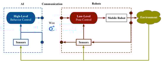
Figure 1.
The proposed centralized architecture for the AUV.
Considering the high cost of make a new mold and the current manufacturing process technology of acrylic cannot be produced a streamlined hull. This paper uses a bullet-shaped hull design as shown in Figure 2, referring the design of the commercially available underwater robots, most of which are cylindrical and oblate. The system architecture is illustrated in Figure 3.
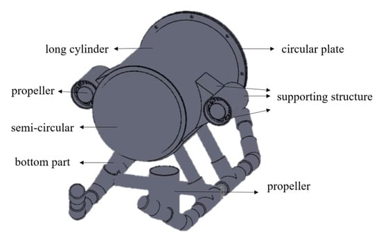
Figure 2.
A bullet-shape 3D model hull design.
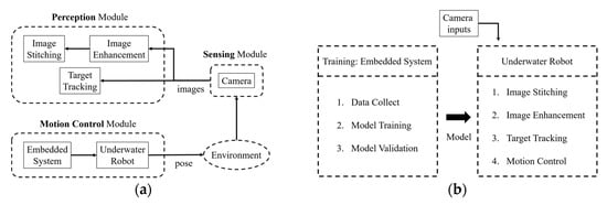
Figure 3.
System architecture listed as: (a) three modules of this system; (b) details of perception module.
2.1. Underwater Image Enhancement
Optical-based imaging is affected severely due to the light absorption and scattering of the underwater turbid medium, which leads to color distortion and low contrast. The red color channel attenuates the fastest in comparison to the blue-green color channels. Therefore, the images taken under water are mostly the effect of blue-green [20]. An underwater image enhancement approach is proposed to solve the above problems, which combines deep learning and image formation model [21].
However, the experimental environment for the proposed system is approximately two meters in the water’s depth, where the red light gradually attenuates, therefore, only part of the image formation model is applicable. The underwater environment suffers from turbid medium resulting low visibility. The obtained image is composed of two parts of light source information, which are directly transmitted light and background scattered light. The background scattered light is caused by the light in the surrounding environment being scattered by a large number of small particles in the water instead of come from the radiation of the object itself. The light directly transmitted comes from the object itself. The formula is as following:
where I(x) is the coordinates of the imaging; x is the image pixel; D(x) is the reflection of the light on the object itself; B is the ambient light; B(1 − t(x)) is the scattered background light. The directly transmitted light will be attenuated, and its magnitude is determined by the attenuation coefficient β and transmission distance d. t(x) is the medium transmission, on the other hand, it means that the proportion of reflected light can smoothly pass through the fogged water and arrive at camera. Scattering may occur when light passes through particles in the water. Only part of the energy D(x)t(x) can be imaged to the camera, which is directly transmitted light.
2.2. Feature-Based Panoramic Image Stitching
Automatic panorama stitching based on SIFT image stitching [22,23,24]. This method has the advantage of using invariant features in the image to match the panoramic image sequence while the input image has uncertainties (e.g., rotation, scaling, and brightness changes). The flowchart as shown in Figure 4.
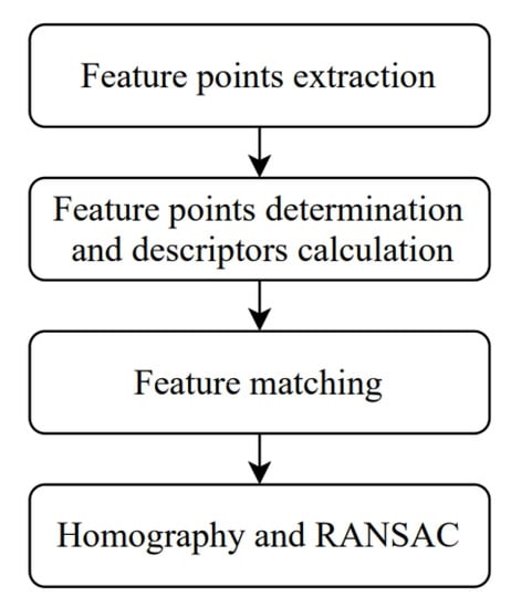
Figure 4.
The flow chart of SIFT-based image stitching.
The first step of the panoramic image stitching algorithm is feature points extraction. The image is composed of flat, edge and corner pixel’s part. The corners are regarded as features usually, which is also the feature points of SIFT. It is obtained according to the Difference of Gaussians (DoG) at different scales-space of the maximum or minimum values, which are as following:
where G (x, y, σ) is a two-dimensional Gaussian function, k is the proportional influence parameter between two adjacent scales, I (x, y) is the pixel coordinate value of the input image, and σ is the standard deviation of Gaussian normal distribution L (x, y, kσ) is the convolution of the original image and the Gaussian blur on the condition that the scale is k times. L (x, y, σ) is the scale-space of the image obtained by convolution of the original image and Gaussian blur. There are subdivided into three parts for the second step, which are feature points location, the directions of the gradient determine, and feature descriptions generation. Eliminate excessive key points and suppress weak feature points that are susceptible to noise after obtaining the feature points, and locate the key points that play an important role in the image. For each Gaussian image, the m (x, y) and direction θ (x, y) of the gradient distribution of each feature point L (x, y) are as following:
where the scale represented by L (x, y) is the current scale of the feature point. The information of the area around the feature point is obtained after the gradient direction is given, and the feature description (e.g., position, coordinate, direction.) is calculated, which is called a descriptor. It allows a slight movement of the edge and a change in proportion without changing the descriptor of SIFT. Third, there are still many feature points between the two images after eliminating and suppressing unnecessary feature points in the feature matching, which is performed to find the corresponding pairing. Define the two images as the reference image Ri and the observation image Si. The paring method applies Euclidean distance as following:
where Ri is the descriptor in the reference image, Si is the descriptor in the observation image, d (Ri, Si) is the similarity measure of any two feature points and n is the dimension. Euclidean distance comparison is used for any dimension j of each image. The feature points are matched when d (Ri, Sj) is less than the threshold. Sj is the closest point from the reference image Ri. Sp is the second closest point from the reference image Ri. The RANSAC (RANdom SAmpling Consensus) is applied to remove the outlier after the matched feature points obtained.
The Homography H to the paring two images is calculated, the feature point of the reference image P and the feature point of the observation image P’ as:
where w is an arbitrary coefficient of H. The H matrix is calculated from the feature points of the two images. The RANSAC is used to searching the best candidate of Homography between the pairing two images. The feature points with the least pairs of calculation H is selected randomly to obtain H and is calculate iteratively to get the best H. Table 1 shows the pseudo code of image stitching using SIFT and RANSAC.

Table 1.
Algorithm of image stitching.
2.3. Siamese Region Proposal Network for Object Tracking
Generally, visual object tracking (VOT) defined as single target tracking. The tracked target is given in the initial frame, and the target is followed in the subsequent frames with bounding box, that is, focusing on correcting the non-specific target repositioning. Be precisely, there are five rigorous criteria to determine whether it belongs to VOT, including monocular, video or image sequence is only obtained from single camera, that is, it does not consider complex applications across cameras (e.g., road monitors); model-free, that is, the model does not know what objects will be framed before obtaining the frame of the initial frame, nor does it need to model the objects in the initial frame in advance; single-target, only tracking the object that selected in the initial frame, apart from this, regarded as background/noise; real-time is an online update process; short-term, once the target is lost, it cannot be re-tracked.
The purpose of target tracking is fast tracking speed and high accuracy. However, the existing correlation filter technology cannot have both at the same time. Usually, it tracks quickly then lack of the ability of adapt to the size change or rotation of the moving object. In 2016, the deep learning-based Siam-FC method proposed a faster tracking speed and better accuracy. However, only the center position of the target can be obtained, and the size of the target cannot be estimated. Similarly, the size of the moving object is affected [12,16,17]. In this paper, deep learning-based SiamRPN is adopted to realize VOT. The sharing weights between templates of the Siamese network architecture overcome the issues of fast motion and low resolution effectively. By region proposal network’s (RPN) multi-scale candidate frame to extract features to reduce the effect from occlusion, background interference, scale change, deformation, and rotation [18,25]. The complete architecture as shown in Figure 5. The Siamese network structure and parameters of the upper and lower branches are the same. The upper is the bounding box of the input initial frame, which is used to detect the target in the candidate area, that is, the template frame. The lower frame is to be detected (real-time or video), that is, detection frame. The middle part is the RPN structure, which is divided into two parts. The upper part is the classification branch. The lower part is the bounding box regression branch. Because there are four quantities [x, y, w, h], the right side of 4k is the output.
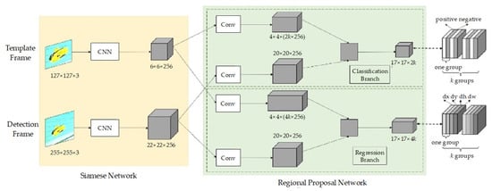
Figure 5.
The architecture of SiamRPN.
First, the principle of Siamese network is the same as the Siam-FC. The image with input size of 127 × 127 × 3 is the template frame z, which is defined as φ(z) after feature extraction by convolutional neural network (CNN). CNN uses a modified AlexNet [26] without cov2 and cov4, and after three layers of fully convolution networks without padding, a 6 × 6 × 256 feature map is obtained. Then, the 6 × 6 × 256 feature map passes through a convolution and becomes a 2k channel (divided into positive and negative), which is a branch of classification and a 4k channel (divided into four variables, dx, dy, dw, dh), which belongs to the branch of bounding box regression. k is the number of anchors. The anchor is based on the feature map to divide rectangular boxes with different ratios on the original image. RPN aligns these boxes for a rough classification and regression, and determines some fine-tuned ones that contain the foreground (positive) and background (negative). Bounding box regression is for better frame the target causes the predicted bounding box is generally not accurate. The anchor of SiamRPN as shown in Figure 6.
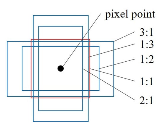
Figure 6.
The anchor of SiamRPN.
The number of anchors is determined by multiplying the ratio of anchors and the number of scales. Since the changes in the tracking process of the before and after frames are not large, the anchor chooses only one scale, ratio = [0.33, 0.5, 1, 2, 3], and the black point in the center is the pixel point of the feature map. After having the background knowledge of RPN, in the middle green part of Figure 5 that the classification branch and the regression branch, respectively, perform convolution operations on the features of the template frame and the detection frame, which with a black dashed line, and equations are as follows:
where Acls contains 2k channels, each point in which represents positive and negative samples, classified by SoftMax activation function; Areg contains 4k channels, each point represents between anchor point and the ground truth, which are dx, dy, dw, dh. For every branch acquires the two outputs of φ(z) and φ(x) of the Siamese network after passing through the convolutional layer (changing the channel dimension) as the input. If there are k anchor points, the network needs to output 2k classification channels and 4k regression channels, therefore, increase the number of channels of φ(z) to [φ(z)]cls and [φ(z)]reg first. The two branches reach 4 × 4 × 256 × 2k and 4 × 4 × 256 × 4k through convolutional layers, respectively, which is the same CNN. Similarly, φ(x) is also divided into two branches [φ(x)]cls and [φ(x)]reg by the two convolutional layers but keep the channel unchanged at 20 × 20 × 256. Black • represents the calculation of the correlation on the classification branch and the regression branch.
The loss function of faster region-based CNN combines the losses of classification and bounding box regression
where λ is the hyper-parameter. The loss function of bounding box regression is
in which
is a robust L1 loss.
where Ax, Ay, Aw, Ah is the x, y coordinate of center point, height and width of the anchor boxes, while Tx, Ty, Tw, Th is of the ground truth boxes. IoU (intersection over union) measure the correlation between ground truth and prediction which is the area of overlapping divided by the area of union part. Positive sample (foreground) have IoU greater than 0.6, while negative sample (background) have IoU less than 0.3.
The above is the training phase. The input is for the training template frame Z, and the two weights obtained after CNN and the convolution layer, which are the weight of the regression branch and the weight of the classification branch, are used as part of the kernel of the detection frame in the tracking phase (obviously, the detection frame is larger than the template frame from Figure 6) as shown in Figure 7.
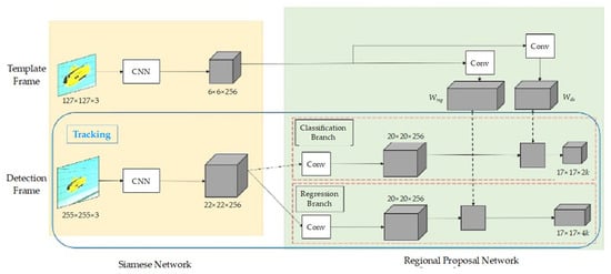
Figure 7.
The tracking phase as one-shot detection.
The tracking phase is a one-shot detection, which the training sample is only one given in the initial frame as:
where (19) is the most basic definition of one-shot detection; L is the average loss; ψ(xi; W) is the prediction function; n is the number of training samples; xi is the training samples; li is the training sample label; and W is the parameter to minimize the loss L.
Applying it to target tracking, it is derived as (20). The purpose is to learn the predictor parameter W from a single template frame z, ω is the forward propagation function, and zi is the template frame, hence, (zi; W’) is mapped to W. Table 2 shows the pseudo code of one-shot detection tracking.
Table 2.
Algorithm of one-shot detection.
Use a Siamese network for feature extraction to generate C(ϕ(Id)), and then input the concatenate features and dimensions D(ϕ(Id)) into the RPN to calculate the similarity score pi and bboxi of the region of interest. It is further addressed on SiamRPN, which is derived as (21), φ is the extraction feature of Siamese network, ζ is the RPN, xi is the detection frame, and zi is the template frame. The purpose is to adjust the W parameter to find the minimized average loss L, and obtain the weight W through the template frame and the detection frame through the CNN and convolution layer. Figure 5 shows that a template frame obtains weights, Wreg and Wcls through CNN and convolution layer, which is utilized as the convolution layer (gray square area) of the detection frame. During the tracking phase, the training phase is offline training, that is, it will no longer update online once the weights are trained, and finally acquire the classification and regression feature map as the coordinates as following:
where I ∈ [0, ]), j ∈ [0, ]), l ∈ [0, 2]), c denotes center, p ∈ [0, ]). The bounding box that far from the center is removed. It is assumed that the object changes little in the before and after frames, therefore, it is selected in a rectangular range smaller than the original feature map. Finally, through non-maximum suppression, the boxes that are not likely and the overlapping boxes are removed. The step is to choose a box with the highest confidence first, and the remaining boxes with its intersection over union are greater than the threshold, then remove them, and so on, until get the final bounding box for tracking the target.
The underwater robot moves forward while the bounding box’s size is under the threshold (object is away from the robot) and moves backward while the bounding box’s size is over the threshold (object is close to the robot). When the bounding box deviates from the center within a certain range, activates the corresponding motor to take corresponding actions. Table 3 shows the pseudo code of tracking target.
Table 3.
Algorithm of target tracking.
3. Results
Most of underwater target tracking prefers pre-recorded videos to verify whether aquatic creatures, man-made objects can be tracked in the screen accurately. However, gradually, [9,10] proposed effective target tracking based on particle filters and correlation filters apply on AUVs. The feature detection, matching and homography matrix calculation is performed by using the OpenCV library. This paper proposes a deep learning based underwater object tracking with low-cost monocular CCD camera for a custom-made underwater vehicle as shown in Figure 8 and Figure 9. The proposed hull design of the underwater vehicle provides low fluid resistance coefficient. The differential drive mechanism using two stepping motors on each side is adopted for the motion control (forward, backward, left turn and right turn).
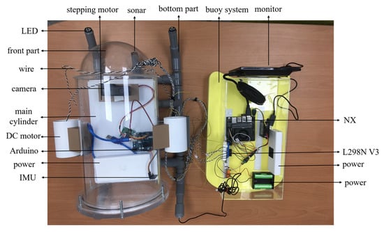
Figure 8.
System component of the underwater vehicle.
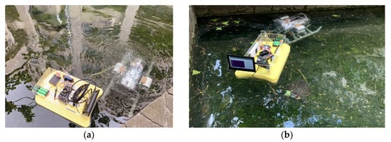
Figure 9.
Underwater vehicle tested in the environment is listed in as: (a) Top view; (b) Side view.
The reason why the structure of the AUV is divided into two parts is to facilitate underwater communication with our surface vehicle [19]. The floating part is designed to be placed on our surface vehicle for the communication with the AUV. The AUV is designed for the tracking of underwater objects around the surface vehicle, it will not be far from our surface vehicle.
The advantage this configuration is also take the computational complexity of the proposed method into consideration, as the hardware equipped on the AUV are always not that powerful. Therefore, the computation is conducted on the surface vehicle. The specifications of the system are shown in Table 4.
Table 4.
Specifications of the AUV system.
The underwater image enhancement was performed as shown in Figure 10. The feature points between the two consecutive image frames are detected as shown in Figure 11. The correspondences are matched as shown in Figure 12. Final panoramic image is stitched as in Figure 13.
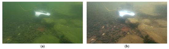
Figure 10.
Image enhancement is listed as: (a) Original; (b) Enhanced.
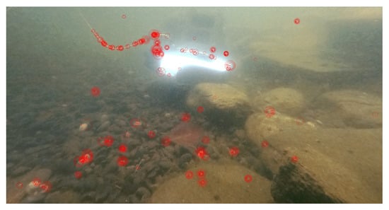
Figure 11.
Feature points detected in the enhanced image.
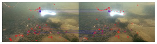
Figure 12.
Correspondences matched among feature points.
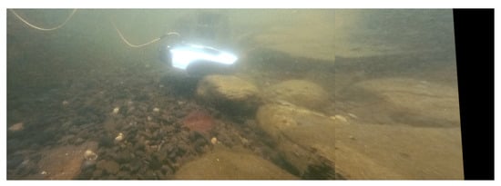
Figure 13.
Final stitched image.
Figure 14 shows the sequences of feature detected and extracted from the real-time data collection during actual underwater cruise. Figure 15 shows the stitched panorama image resulted from the cruise in Figure 14.
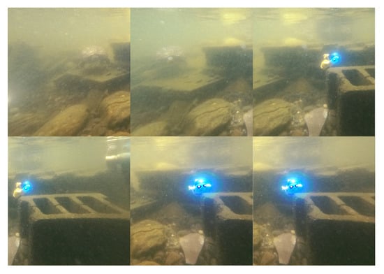
Figure 14.
Sequences of feature detected and extracted.
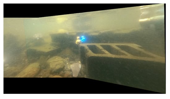
Figure 15.
Stitched panorama image.
The underwater target tracking illustrated in Table 3 is implemented as shown in Figure 16 (i.e., image frame 25, 50, 75, and 100). The tracking can be achieved in the presence of occlusions and rotation of the target. The results show that the algorithm can adapt to the scale change of the target.
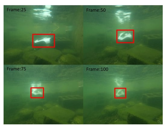
Figure 16.
Actual underwater target tracking.
Three datasets are used to evaluate the performance of the visual tracking algorithm as follows:
- Visual Object Tracking (VOT2018) dataset [27];
- Object Tracking Benchmark dataset (OTB100) [28];
- Real-time video sequences collected by the proposed system.
The following target tracking algorithm are used for the performance evaluation with the above dataset.
- 4.
- SiamRPN (proposed in this paper);
- 5.
- Efficient Convolution Operators for Tracking (ECO);
- 6.
- Continuous Convolution Operators (C-COT);
- 7.
- Distractor-aware Siamese Networks for Visual Object Tracking (DaSiamRPN).
3.1. VOT2018 Data Set
The metrics to evaluate the above tracker’s performance are listed as follows:
- Accuracy;
- Robustness;
- Number of lost frames;
- Expected average overlap (EAO).
Accuracy is the average overlap rate of the tracker under a test sequence. The area of the intersecting part of the two rectangular boxes is divided by the area of the merged part of the two rectangular boxes (MeanIOU) as:
where t, N is frame number, AG is ground truth of target, AP is predicted output position and Φ is accuracy of current frame.
Robustness is the number of tracker failures under a test sequence. It is judged to fail when the overlap rate is 0, which is calculated as following:
where F (i, k) is the number of failed tracking, k is the index of measurement repeated N times.
The Number of Lost Frames is the total number of lost image sequences in the testing (VOT2018). EAO is the expected value of the non-reset overlap of each tracker on a short-term image sequence, and it is the most important indicator for VOT to evaluate the accuracy of the tracking algorithm as:
where Nhigh and Nlow is the length of sequence, ΦNS is average overlap.
Table 5 compares the metrics for each tracker. The confusion matrix obtained from applying proposed SiamRPN tracker is shown in Table 6 and the metric of evaluation are listed in Table 7.
Table 5.
Metrics to evaluate model’s performance using VOT2018 of data set.
Table 6.
Confusion matrix from propose tracker’s (SiamRPN) using VOT2018 dataset.
Table 7.
Metrics to evaluate propose tracker’s (SiamRPN) performance using VOT2018 dataset.
3.2. OTB100 Data Set
Table 8 compares the metrics to evaluate the above tracker’s performance and are listed as follows:
Table 8.
Metrics to evaluate model’s performance using OTB100 data set.
- Success;
- Precision.
3.3. Real-Time Data Collected by the Proposed System
The testing data of target tracking were collected using the proposed underwater vehicle at a pond and swimming pool. The testing site (pond) had the presence of variation on illumination and occlusion (rocks, turtles and fished). The illumination descriptions of two testing data sets are summarized as:
- Data set A, contains 1264 samples under the illumination of sunlight at daytime;
- Data set B, contains 402 samples the illumination of onboard LED light source at night.
The confusion matrix for both dataset A and B is shown in Table 9 and Table 10, respectively. Table 11 compares the metrics (accuracy precision, recall and F1 score) to evaluate the SiamRPN tracker’s performance for both data set.
Table 9.
Confusion matrix of model using dataset A.
Table 10.
Confusion matrix of model using dataset B.
Table 11.
Metrics to evaluate propose tracker’s (SiamRPN) performance.
The P-R (Precision-Recall) curve of for the whole datasets (A and B) is shown in Figure 17. The ROC curve (Receiver Operating Characteristic Curve) the whole datasets (A and B) is shown in Figure 18. The ROC curve shows the performance of the model at all thresholds (True Positive Rate vs. False Positive Rate). The orange line denotes ROC curve and the blue line denotes linear. The AUC (Area under the ROC Curve) is 0.66.
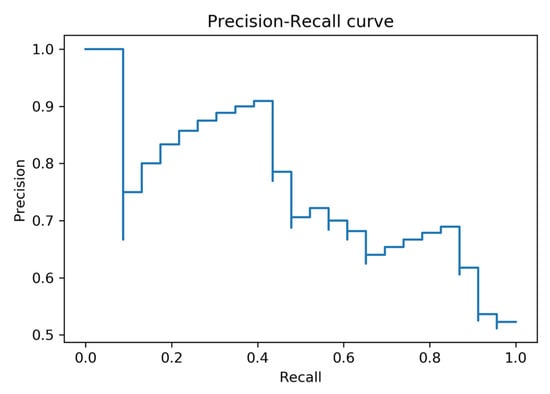
Figure 17.
P-R curve for the merged data set (A and B).
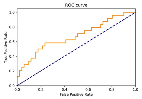
Figure 18.
ROC curve for the merged data set (A and B).
4. Discussion
The proposed system applied SiamRPN based on deep learning to effectively track the underwater moving target. The current findings expand prior work [19], neighborhood tracking of underwater objects for the unmanned surface vehicle. The computation conducted onboard the surface vehicle reduce the insufficient power issue of the underwater vehicle.
As mentioned in the literature review [12,16,17], the deep learning-based Siam-FC approach shows a faster tracking speed and better accuracy. However, their approach suffers from only acquire the center position of the target, while the size of the target cannot be estimated (e.g., detection bounding box size is fixed). The size of detection bounding box changed proportionally to the target sized in the proposed system.
The proposed SiamRPN approach share weights between templates of the Siamese network architecture overcome the issues of fast motion and low resolution effectively. The results are in general agreement with [18,25], which extract features by RPN (region proposal network’s)’s multi-scale candidate frame can reduce the effect from occlusion, background interference, scale change, deformation, and rotation.
The performance comparison among trackers using VOT2018 data set are summarized as:
- EAO of proposed tracker (SiamRPN) is 0.318 which outperforms the deep-learning based tracker (DaSiamRPN);
- Robustness index of proposed tracker (SiamRPN) is 0.337, which outperform the other 2 trackers (C-COT and ECO) and equivalent to deep-learning based tracker (DaSiamRPN);
- Accuracy of proposed tracker (SiamRPN) is 0.601, which outperforms the other 2 trackers (C-COT and ECO) and equivalent to deep-learning based tracker (DaSiamRPN);
- Metrics to evaluate propose tracker’s (SiamRPN) performance as Accuracy (60%), Precision (60%), Recall (68%) and F1 (63%).
The performance comparison among trackers using OTB100 data set are summarized as:
- Proposed SiamRPN show a 0.696 success and 0.914 precision outperforms the other trackers;
- Proposed SiamRPN is more robust than the other trackers in the presence of uncertainties, include the variation on illumination, scale, occlusion, motion blur, motion speed, in-plane/out-of-plane rotation, out-of-view, background clutters and resolution.
The performance comparison among trackers using real-time data collected by the proposed system are summarized as:
- Data set A (sunlight at daytime) outperform data set B (onboard LED light source at night) from the aspect of accuracy (66% vs. 61%), precision (76% vs. 63%) and F1 (73% vs. 68%);
- B (onboard LED light source at night) outperform data set data set A (sunlight at daytime) from the aspect of recall (72% vs. 71%);
- ROC curve of the whole datasets (A and B) shows the performance of the model at all thresholds (True Positive Rate vs. False Positive Rate);
- AUC is 0.66.
The tracking effect at night is worse than that during the day. Even if the LED light source onboard the AUV, the effect of tracking moving targets is still not as good as daylight. The preliminary results demonstrate the feasibility of real-time underwater target tracking using a low-cost underwater robot with onboard embedded system and CCD camera. The findings and their implications in the broadest context are summarized as:
- Hierarchical control architecture can speed up the processing, the low-level pose control (Arduino) and the high-level tracking-behavior control (Nvidia Jetson Xavier NX).
- Image enhancement reduces the color distortion and greatly improves the drawback of insufficient feature points for successful corresponding matching;
- Image stitching reduces the blind spots of the viewpoint and the resultant panoramic images includes more objects can be used for other classification purpose;
- Target tracking improves the issues on target loss and mis-tracking;
- Low-cost underwater vehicle and single camera.
The underwater tracking suffers from many uncertainties (e.g., varying turbidity and low visibility) that affect the detection and tracking performance severely, however, the result still demonstrated the effectiveness of the proposed method and outperform the other trackers for the scenario in this paper. Future research directions are highlighted as:
- Add more behavior (i.e., obstacle avoidance, trajectory tracking and team formation) in high-level control and pose following in low-level control;
- Test and evaluate tracking performance under more variations (uncertainties) from the environment, robot/sensor and object;
- Try different configurations for generating a panorama image (e.g., multiple cameras, fish-eye lens, etc.) and placed outside the vehicle with waterproof capability;
- Implement sensor fusion (heterogeneous or homogeneous) for uncertainty reduction to have more accurate, complete and dependable readings;
- Integrate the manipulator to extend the capability of the unmanned surface vehicle (e.g., water sampling).
Author Contributions
Conceptualization, M.-F.R.L.; methodology, M.-F.R.L. and Y.-C.C.; software, Y.-C.C.; validation, M.-F.R.L. and Y.-C.C.; formal analysis, M.-F.R.L.; investigation, M.-F.R.L.; resources, M.-F.R.L.; data curation, Y.-C.C.; writing—original draft preparation, Y.-C.C.; writing—review and editing, M.-F.R.L.; visualization, Y.-C.C.; supervision, M.-F.R.L.; project administration, M.-F.R.L.; funding acquisition, M.-F.R.L. All authors have read and agreed to the published version of the manuscript.
Funding
This research was funded by the Ministry of Science and Technology (MOST) in Taiwan, grant number [108-2221-E-011-142-] and the Center for Cyber-physical System Innovation from the Featured Areas Research Center Program within the framework of the Higher Education Sprout Project by the Ministry of Education (MOE) in Taiwan.
Institutional Review Board Statement
Not applicable.
Informed Consent Statement
Not applicable.
Data Availability Statement
Not applicable.
Conflicts of Interest
The authors declare no conflict of interest.
References
- Schjølberg, I.; Gjersvik, T.B.; Transeth, A.A.; Utne, I.B. Next Generation Subsea Inspection, Maintenance and Repair Operations. IFAC Pap. 2016, 49, 434–439. [Google Scholar] [CrossRef]
- Martins, A.; Almeida, J.; Almeida, C.; Dias, A.; Dias, N.; Aaltonen, J.; Heininen, A.; Koskinen, K.T.; Rossi, C.; Dominguez, S.; et al. UX 1 system design—A robotic system for underwater mining exploration. In Proceedings of the 2018 IEEE/RSJ International Conference on Intelligent Robots and Systems (IROS), Madrid, Spain, 1–5 October 2018; pp. 1494–1500. [Google Scholar]
- Wang, G.; Hwang, J.; Williams, K.; Cutter, G. Closed-Loop Tracking-by-Detection for ROV-Based Multiple Fish Tracking. In Proceedings of the 2016 ICPR Workshop on Computer Vision for Analysis of Underwater Imagery, Cancun, Mexico, 4 December 2016; pp. 7–12. [Google Scholar]
- Marques, M.M.; Gatta, M.; Barreto, M.; Lobo, V.; Matos, A.; Ferreira, B.; Santos, P.J.; Felisberto, P.; Jesus, S.; Zabel, F.; et al. Assessment of a Shallow Water Area in the Tagus Estuary Using Unmanned Underwater Vehicle (or AUV’s), Vector-Sensors, Unmanned Surface Vehicles, and Hexacopters—REX’17. In Proceedings of the 2018 OCEANS—MTS/IEEE Kobe Techno-Oceans, Kobe, Japan, 28–31 May 2018; pp. 1–5. [Google Scholar]
- Ji, J.; Sun, Y.; Zhou, T.; Xu, J. Study on method of cooperative laying mines with submarine and reconnaissance force based on joint blockade combat. In Proceedings of the IEEE International Conference on Computer Supported Cooperative Work in Design, Nanchang, China, 4–6 May 2016; pp. 31–34. [Google Scholar]
- Xu, F.; Ding, X.; Peng, J.; Yuan, G.; Wang, Y.; Zhang, J.; Fu, X. Real-Time Detecting Method of Marine Small Object with Underwater Robot Vision. In Proceedings of the 2018 OCEANS—MTS/IEEE Kobe Techno-Oceans, Kobe, Japan, 28–31 May 2018; pp. 1–4. [Google Scholar]
- Rout, D.K.; Subudhi, B.N.; Veerakumar, T.; Chaudhury, S. Walsh–Hadamard-Kernel-Based Features in Particle Filter Framework for Underwater Object Tracking. IEEE Trans. Ind. Inform. 2020, 16, 5712–5722. [Google Scholar] [CrossRef]
- Jing, C.; Lin, Z.; Li, J. Detection and tracking of an underwater target using the combination of a particle filter and track-before-detect. In Proceedings of the OCEANS—Shanghai, Shanghai, China, 10–13 April 2016; pp. 1–5. [Google Scholar]
- Zhao, B.; Liang, Y.; Dong, X.; Li, Q.; Ren, Z. An Improved Motion Capture System for Multiple Wheeled Mobile Robots Based on KCF and GMM. In Proceedings of the Chinese Control Conference, Guangzhou, China, 27–30 July 2019; pp. 4095–4100. [Google Scholar]
- Kong, S.; Fang, X.; Chen, X.; Wu, Z.; Yu, J. A real-time underwater robotic visual tracking strategy based on image restoration and kernelized correlation filters. In Proceedings of the Chinese Control and Decision Conference, Shenyang, China, 9–11 June 2018; pp. 6436–6441. [Google Scholar]
- Bertinetto, L.; Valmadre, J.; Henriques, J.F.; Vedaldi, A.; Torr, P.H.S. Fully-Convolutional Siamese Networks for Object Tracking. In Lecture Notes in Computer Science; Hua, G., Jégou, H., Eds.; Springer: Cham, Switzerland, 2016; Volume 9914, pp. 850–865. [Google Scholar]
- Jia, S.; Zang, R.; Li, X.; Zhang, X.; Li, M. Monocular Robot Tracking Scheme Based on Fully-Convolutional Siamese Networks. In Proceedings of the Chinese Automation Congress, Xi’an, China, 30 November–2 December 2018; pp. 2616–2620. [Google Scholar]
- Mesquita, D.B.; Santos, R.F.; Macharet, D.G.; Campos, M.F.M.; Nascimento, E.R. Fully Convolutional Siamese Autoencoder for Change Detection in UAV Aerial Images. IEEE Geosci. Remote Sens. Lett. 2020, 17, 1455–1459. [Google Scholar] [CrossRef]
- Bosch, J.; Istenič, K.; Gracias, N.; Garcia, R.; Ridao, P. Omnidirectional Multicamera Video Stitching Using Depth Maps. IEEE J. Ocean. Eng. 2020, 45, 1337–1352. [Google Scholar] [CrossRef]
- Wang, Y.; Song, W.; Fortino, G.; Qi, L.; Zhang, W.; Liotta, A. An Experimental-Based Review of Image Enhancement and Image Restoration Methods for Underwater Imaging. IEEE Access 2019, 7, 140233–140251. [Google Scholar] [CrossRef]
- Wang, C.; Sun, X.; Chen, X.; Zeng, W. Real-Time Object Tracking with Motion Information. In Proceedings of the IEEE Visual Communications and Image Processing, Taichung, Taiwan, 9–12 December 2018; pp. 1–4. [Google Scholar]
- Pang, H.; Xuan, Q.; Xie, M.; Liu, C. Target Tracking Based on Siamese Convolution Neural Networks. In Proceedings of the International Conference on Computer, Information and Telecommunication Systems, Hangzhou, China, 5–7 October 2020; pp. 1–5. [Google Scholar]
- Fan, H.; Ling, H. Siamese Cascaded Region Proposal Networks for Real-Time Visual Tracking. In Proceedings of the IEEE/CVF Conference on Computer Vision and Pattern Recognition, Long Beach, CA, USA, 15–20 June 2019; pp. 7944–7953. [Google Scholar]
- Lee, M.-F.R.; Lin, C.-Y. Object Tracking for an Autonomous Unmanned Surface Vehicle. Machines 2022, 10, 378. [Google Scholar] [CrossRef]
- Zhang, W.; Dong, L.; Pan, X.; Zou, P.; Qin, L.; Xu, W. A Survey of Restoration and Enhancement for Underwater Images. IEEE Access 2019, 7, 182259–182279. [Google Scholar] [CrossRef]
- Chen, X.; Zhang, P.; Quan, L.; Yi, C.; Lu, C. Underwater Image Enhancement based on Deep Learning and Image Formation Model. arXiv preprint 2021, arXiv:2101.00991. [Google Scholar]
- Jiang, P.; Wei, Q.; Chen, Y.; Yang, C.; Fan, J.; Shou, Z.; Huang, Z. Real-time panoramic system for underwater cleaning robot. In Proceedings of the International Conference on Mechanical and Intelligent Manufacturing Technologies, Cape Town, South Africa, 10–13 February 2018; pp. 155–159. [Google Scholar]
- Ji, X.; Xiang, X.; Huang, J. Real-Time Panorama Stitching Method for UAV Sensor Images Based on the Feature Matching Validity Prediction of Grey Relational Analysis. In Proceedings of the International Conference on Control, Automation, Robotics and Vision, Singapore, 18–21 November 2018; pp. 1454–1459. [Google Scholar]
- Gallardo, E.C.; Garcia, C.F.M.; Zhu, A.; Silva, D.C.; González, J.A.G.; Ortiz, D.M.; Fernández, S.; Urriza, B.; López, J.V.; Marín, A.; et al. A Comparison of Feature Extractors for Panorama Stitching in an Autonomous Car Architecture. In Proceedings of the International Conference on Mechatronics, Electronics and Automotive Engineering, Cuernavaca, Mexico, 26–29 November 2019; pp. 50–55. [Google Scholar]
- Zhou, H.; Ni, B. Tracking of drone flight by neural network Siamese-RPN. In Proceedings of the International Conference on Engineering, Applied Sciences and Technology, Chiang Mai, Thailand, 1–4 July 2020; pp. 1–3. [Google Scholar]
- Shelhamer, E.; Long, J.; Darrell, T. Fully Convolutional Networks for Semantic Segmentation. IEEE Trans. Pattern Anal. Mach. Intell. 2017, 39, 640–651. [Google Scholar] [CrossRef]
- Kristan, M.; Leonardis, A.; Matas, J.; Felsberg, M.; Pflugfelder, R.; Čehovin Zajc, L.; Vojir, T.; Bhat, G.; Lukezic, A.; Eldesokey, A.; et al. The sixth visual object tracking VOT2018 challenge results. In Proceedings of the 15th European Conference on Computer Vision, ECCV 2018, 8–14 September 2018; Springer: Munich, Germany, 2018. [Google Scholar]
- Wu, Y.; Lim, J.; Yang, M.H. Object Tracking Benchmark. IEEE Trans. Pattern Anal. Mach. Intell. 2015, 37, 1834–1848. [Google Scholar] [CrossRef]
Disclaimer/Publisher’s Note: The statements, opinions and data contained in all publications are solely those of the individual author(s) and contributor(s) and not of MDPI and/or the editor(s). MDPI and/or the editor(s) disclaim responsibility for any injury to people or property resulting from any ideas, methods, instructions or products referred to in the content. |
© 2023 by the authors. Licensee MDPI, Basel, Switzerland. This article is an open access article distributed under the terms and conditions of the Creative Commons Attribution (CC BY) license (https://creativecommons.org/licenses/by/4.0/).