Article

Lab Experiments for Abrasive Waterjet Perforation and Fracturing in Offshore Unconsolidated Sandstones

1
Bohai Petroleum Research Institute, Tianjin Branch, CNOOC (China) Co., Ltd., Tianjin 300452, China
2
National Key Laboratory of Petroleum Resources and Engineering, China University of Petroleum (Beijing), Beijing 102249, China
*
Author to whom correspondence should be addressed.
Processes 2023, 11(11), 3137; https://doi.org/10.3390/pr11113137
Submission received: 22 September 2023 / Revised: 18 October 2023 / Accepted: 30 October 2023 / Published: 2 November 2023

Abstract

:
Multistage hydraulic fracturing has been proven to be an effective stimulation method to extract more oil from the depleted unconsolidated sandstone reservoirs in Bohai Bay, China. The offshore wellbores in this area were completed with a gravel pack screen that is much too difficult to be mechanically isolated in several stages. Hydra-jet fracturing technology has the advantages of multistage fracturing by one trip, waterjet perforation, and hydraulic isolation. The challenges of hydraulic-jet fracturing in offshore unconsolidated sandstone reservoir can be summarized as follows: the long jet distance, high filtration loss, and large pumping rate. This paper proposes full-scale experiments on the waterjet perforation of unconsolidated sandstone, waterjet penetration of screen liners and casing, and pumping pressure prediction. The results verified that multistage hydra-jet fracturing is a robust technology that can create multiple fractures in offshore unconsolidated sandstone. Lab experiments indicate that the abrasive water jet is capable to perforate the screen-casing in less than one minute with an over 10 mm diameter hole. The water jet perforates a deep and slim hole in unconsolidated sandstone by using less than 20 MPa pumping pressure. Recommended perforating parameters: maintain 7% sand concentration and perforate for 3.0 min. Reduce sand ratio to 5%, maintain 3.0 m3/min flow rate, and continue perforating for 7.0 min. The injection drop of the nozzle accounts for more than 62% of the tubing pump pressure. The recommended nozzle combinations for different fracturing flow rates are 8 × ø6 mm or 6 × ø7 mm for 2.5 m3/min and 3.0 m3/min, and 8 × ø7 mm for 3.5 m3/min and 4.0 m3/min. A one-trip-multistage hydra-jet fracturing process is recommended to be used for horizontal wells in offshore unconsolidated sandstone reservoirs.

1. Introduction

Hydraulic fracturing of unconsolidated sandstones has become an important technique used to enhance oil recovery for the offshore reservoirs [1]. The first hydraulic fracturing of offshore unconsolidated sandstone appeared in the Gulf of Mexico [2], following successful cases in Brazil, Nigeria, and Bohai Bay. However, gravel pack screen completion is popular in unconsolidated sandstone oil wells and it is much too difficult to deploy multistage hydraulic fracturing using mechanical isolation [3]. Flexible multistage hydraulic fracturing technology for use in unconsolidated sandstones is required.
Abrasive waterjet (AWJ) fracturing stimulation, also called hydra-jet fracturing, has been accepted as an effective and efficient stimulation technique for multistage well completion used with casing, slotted liners, and even open hole [4]. Major technical advantages include the integration of AWJ perforation and fracturing, hydraulic isolation capacity, pinpoint fracture initiation, unlimited stages, and high efficiency [5]. It has become a flexible technology used to achieve multistage fracturing in offshore reservoir stimulation [6]. Hydra-jet fracturing was first used in horizontal wells with uncemented and pre perforated liners, off the shore of Brazil in 2004, which proved its effectiveness in offshore multistage stimulation [7]. Following the first implementation of hydra-jet fracture, acidizing was used with great success in deep water fields off the shore Brazil in 2005 [8]. Hydra-jet propped fracturing was tested in mature offshore oil fields in Congo with low to moderate permeability of sandstone in 2008 and 2010 [9]. The first completed hydra-jet fracturing multizone application was performed in an offshore high-permeability oil well located in the Bozhong oil field in Bohai Bay, China, and has proven successful since 2020 [10]. Although several successful cases are present in offshore reservoir stimulation [11], engineering challenges still exist to be solved, as illustrated in Figure 1. First, abrasive waterjet perforation becomes more challenging since several penetration layers are present, including the slotted linear layer, the gravel pack layer, the casing, and the cement shield [12]. The waterjet standoff distance becomes larger in contrast to the onshore cemented casing [13], so the waterjet energy reduces too much to penetrate a large and deep perforating hole in unconsolidated sandstone. It is significant to evaluate the capacity of waterjet perforation for offshore unconsolidated sandstone [14,15]. The jet rate, sand ratio, and injection time need to be verified. Second, unconsolidated sandstone is a type of medium with a low strength, less than 10 MPa, and high permeability, over 200 mD [16,17,18]. The perforation morphology of unconsolidated sandstone is different from that of conventional rock, which will affect the jet gun design and injection parameter design.
This study proposes lab experiment schemes to validate abrasive waterjet perforation and multistage fracturing in unconsolidated sandstone, including full-scale abrasive waterjet penetration through the screen liner and waterjet rock perforation. In Section 2, the recommended jet rate is obtained via lab experiments. In Section 3, the nozzle combination is optimized using the recommended jet rate. A bottom-hole tool string and procedure design for offshore Hydra-jet fracturing are recommended. In Section 4, the feasibility of hydra-jet fracturing in an offshore unconsolidated sandstone reservoir is verified using a well in Bohai Bay.

2. Abrasive Waterjet Perforation in Gravel Pack Completion

Abrasive waterjet perforation in an offshore unconsolidated sandstone reservoir is shown in Figure 2. The perforating fluid enters the tubing and is accelerated through the nozzle [19,20,21]. Several layers, including the screen liner, the gravel pack, casing, cement, and formation rock, are penetrated by waterjet. In order to avoid serious damage to the unconsolidated sandstone formation, we plan to first penetrate the screen liner, gravel, casing, and cement, and then perforate the unconsolidated sandstone. A full-scale experiment was proposed to obtain the relationship between the abrasive waterjet rate and the perforating time. The feasibility of the waterjet perforating the unconsolidated sandstone was verified by comparing the waterjet’s impact on unconsolidated sandstone and red sandstone. The characteristics of the perforating shape in unconsolidated sandstone were obtained.

2.1. Capacity of Abrasive Waterjet Penetrating Screen Liner and Casing

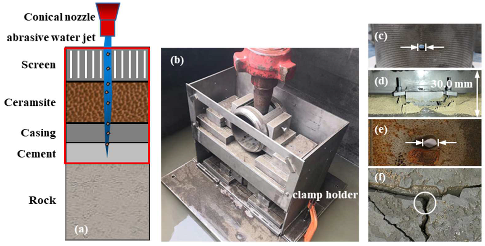
The full-scale lab simulator was developed to simulate the physical behaviors of abrasive waterjet penetration through several layers including the screen liner, the gravel pack, the casing, and the cement shield, as illustrated in Figure 2. The specific parameters of the experiment are designed according to typical well parameters, and this information is shown in Table 1. An STP 600 plunger pump (Sinopec Oilfield Equipment Corporation, China) with a maximum flow rate of 1000 L/min was used to generate the abrasive waterjet. The distance from the nozzle outlet to the screen was set to 5 mm. The experiment was carried out under submerged conditions. Concentric holes appeared in the screen liner and casing (Figure 2c,e). The gravel pack and cement were easily penetrated by the abrasive waterjet (Figure 2d,f). It took only a moment for the abrasive waterjet to destroy the gravel pack and cement. In addition, the gravel layer and cement had little effect on screen and casing damage. Thus, we only studied the perforation of the screen liner and casing.
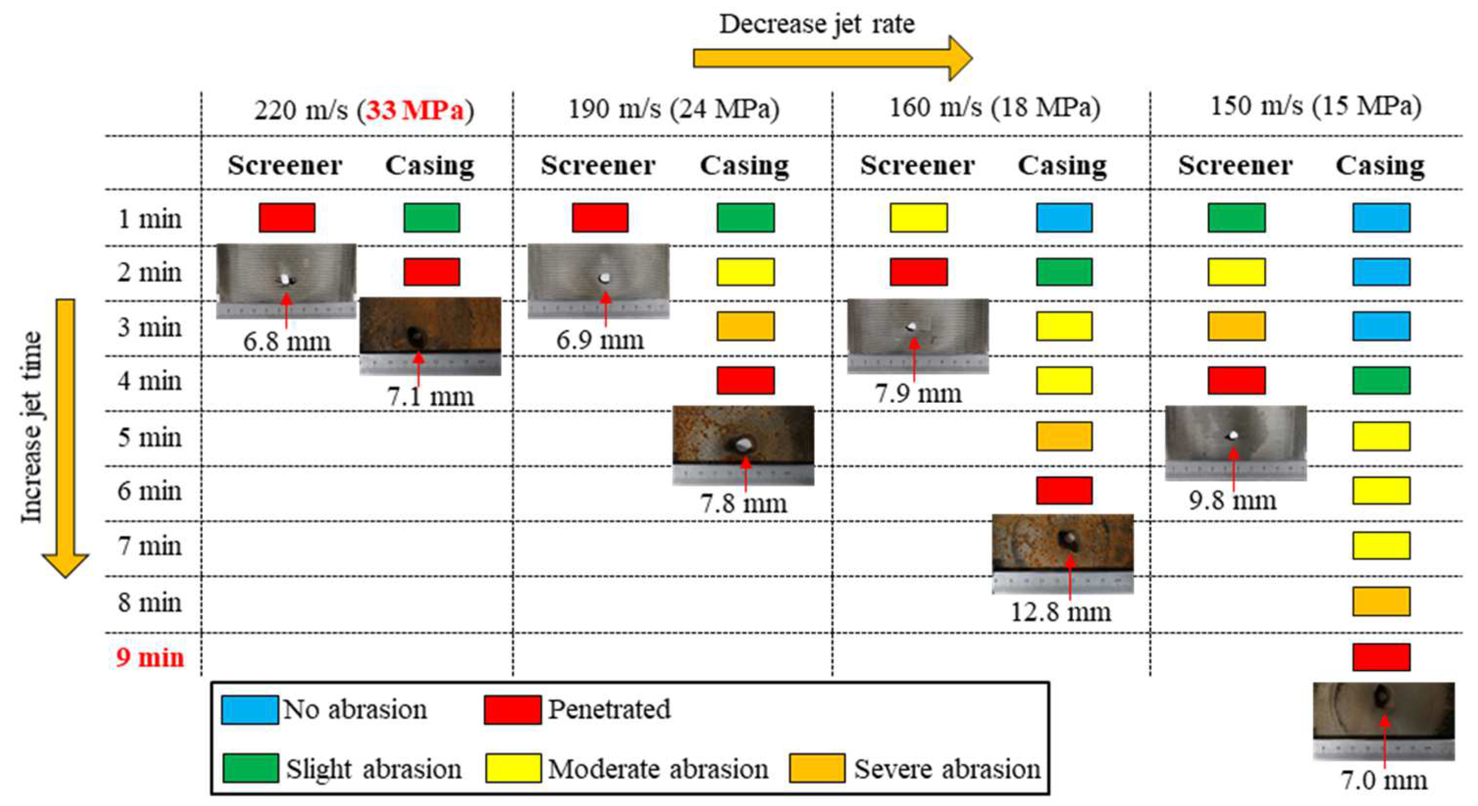
We obtained the relationship between the abrasive waterjet rate and jet time by looking at the penetration time and decreasing the injection velocity step by step (Figure 3). When the nozzle pressure approaches the limit 35 MPa, the jet velocity is 220 m/s, which is taken as the upper limit. We observed the screen and casing penetration every minute until the casing was penetrated. For example, when the jet rate was 220 m/s, after one minute the screen was penetrated and the casing was slightly abraded. After another minute, the casing was penetrated. Therefore, the critical jet time at 220 m/s is 2 min. As the pumping rate decreases, the ability of the abrasive waterjet to penetrate the screen-casing decreases. The critical jet times for 190 m/s, 160 m/s, and 150 m/s are 4 min, 6 min, and 9 min, respectively. When the jet velocity is 150 m/s, the jet time approaches the limit of 10 min, thus 150 m/s is taken as the lower limit. The penetration diameter is comprehensively affected by jet distance, jet rate, and jet time. Under the experimental conditions used in this study, the penetration diameter of the screen is 1.36 to 1.96 times the diameter of the nozzle. The penetration diameter of the casing is 1.40 to 2.56 times the diameter of the nozzle.

2.2. Capacity of Waterjet Perforation in Unconsolidated Sandstone

The unconsolidated sandstone is our target material and these samples were collected from a drilling core from the Bohai Bay formation at a depth of 1600 m. In order to make the blank group, the red sandstone was selected from natural outcrops in Sichuan. Table 2 compares their physical and mechanical properties.
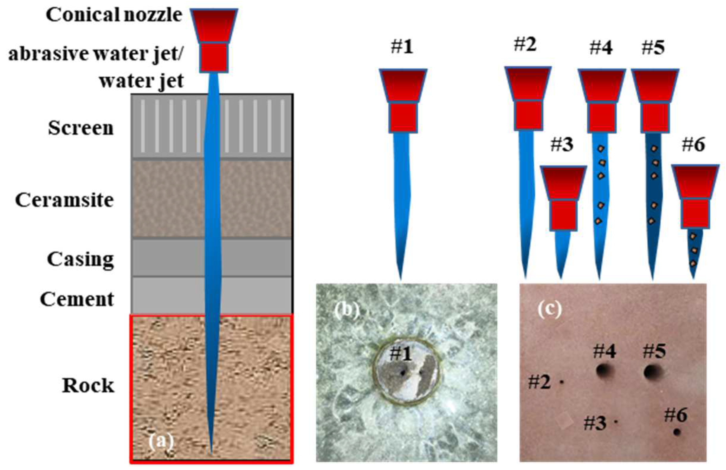
Considering the coring size of ø25 × 50 mm and the large jet distance, a nozzle with 1 mm outlet diameter is used in this experiment (Figure 4a). The injection time is 10 s. For these two types of rocks, jet rock breaking was carried out six times, including five experimental conditions (Figure 4b,c). The unconsolidated sandstone is perforated under waterjet as result #1 (Figure 4b). For results #2 to #6, the red sandstone is jetted, and the jet conditions are changed until the perforating depth of the red sandstone is close to that of the unconsolidated sandstone. The feasibility of the waterjet perforating the unconsolidated sandstone is verified via comparison with the red sandstone, and the perforating characteristics of unconsolidated sandstone are obtained via CT scan.
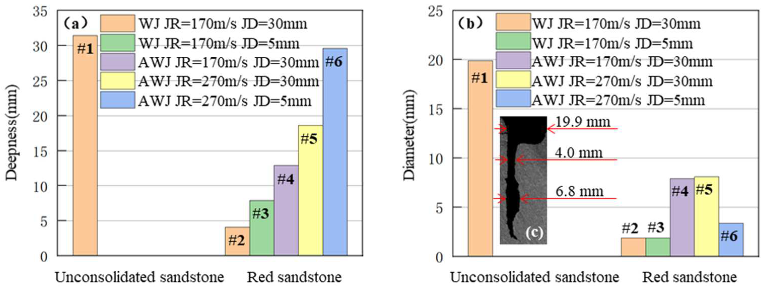
In Figure 5a, result #1 and result #2 show that the rock breaking depth of unconsolidated sandstone is 7.7 times that of red sandstone under the same jet conditions. By changing the waterjet (WJ) into an abrasive waterjet (AWJ), increasing the jet rate (JR) to 270 m/s, and reducing the jet distance (JD) to 5 mm, the rock-breaking depth of #6 of the red sandstone is approximated to the rock-breaking depth of #1 of the unconsolidated sandstone. In addition, the jet parameters of #6 are similar to those of onshore construction, which proves that the waterjet has the ability to perforate unconsolidated sandstone under a large jet distance. Figure 5b,c shows that the rock breaking diameter of unconsolidated sandstone is generally larger than that of red sandstone. Through the rock breaking diameter of the red sandstone under different jet conditions, it is found that the higher the rock-breaking efficiency and the larger the jet distance, the larger the rock-breaking diameter. Unconsolidated sandstone is easy to break, and the offshore perforation is mostly at a large jet distance. Therefore, tools and processes need to be optimized to avoid large perforation diameters in offshore unconsolidated sandstone reservoirs.

3. Optimization of Bottom-Hole Tool and Procedures of Offshore Hydra-Jet Fracturing

3.1. Optimization of Key Parameters of Waterjet Nozzles

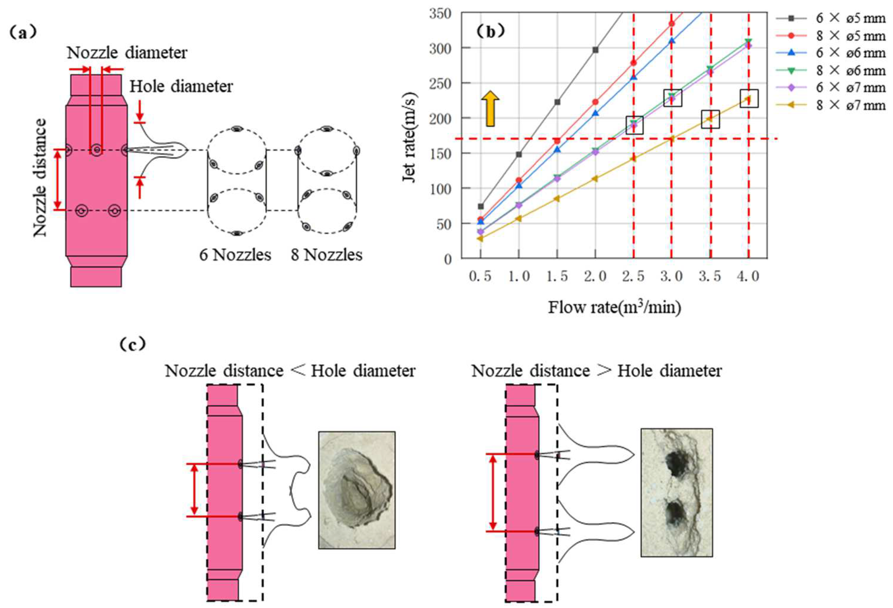
The waterjet nozzles are critical parts in the transfer of high-pressure energy to kinetic energy with a high velocity impact. The nozzle diameter and its number are two key parameters for the hydra-jet fracturing tool. Two aspects of nozzle design should be taken into account. The first point is to reach the minimum waterjet velocity to reserve enough energy for the perforation. The second aspect is to satisfy the requirement of pumping rate. The formula for nozzle pressure drop is as follows:
P b = 513.559 V 2 ρ C 2
where P b is nozzle pressure drop, MPa; V = Q A is jet rate, m/s; Q is flow rate, L/s; A = 0.25 π D 2 is outlet area of all nozzles, mm2; D is nozzle diameter, mm; ρ is fluid density, g/cm3; and C is discharge coefficient of nozzle, generally 0.9.
Figure 6 illustrates the workflow to optimize the nozzles parameters. The waterjet perforation experiments indicate that the critical waterjet velocity required is up to 190 m/s to make a deep and large perforating hole. Figure 6b indicates the correlation between pumping rate and waterjet velocity. If the required pumping rate is above 3.0 m3/min, the corresponding nozzle diameter and number can be optimized as 8 × ø6 mm or 6 × ø7 mm. If the pumping rate is over 3.5 m3/min, the corresponding nozzle diameter and number can be 8 × ø7 mm. Except for the nozzle diameter and numbers, the nozzle distance between the two layers, as shown in Figure 6c, is another key parameter to be considered. According to the perforation experiment on unconsolidated sandstone, the hole diameter is 20 times that of of the nozzle diameter. Therefore, the recommended nozzle distance between the two layers is 200 mm to avoid the connection of multiple perforating holes.

3.2. Design of Bottom-Hole Tool String for Offshore Hydra-Jet Fracturing

The key point of bottom-hole tool design is to avoid the sand sticking issue while trialing the hydra-jet tool. Thus, we selected an elastic, deformable centralizer and a spherical guide shoe. The trailing-tool was recommended for horizontal multistage hydraulic-jet fracturing in an offshore unconsolidated sandstone reservoir. Figure 7 illustrates the tool string, including guide shoe, multi-hole pipe, one-way valve, Hydra-jet body with nozzles, and the elastic, deformable centralizers. The spherical guide shoe is used to ensure the tool is capable of passing the inner steps of wellbore. The multi-hole pipe and one-way valve allows pre-washing job and reverse circulation washing. The elastic deformable centralizer makes the hydra-jet body centralized and reduces the risk of sand sticking issue.

3.3. Hydra-Jet Fracturing Process

There are two typical types of hydra-jet fracturing, involving the trailing frac-string process and non-tripping frac-string process [22,23,24]. In order to reduce the risk of the sand sticking issue, the trailing frac-string process was recommended for offshore sand packing well completion. The detailed steps include the hydra-jet tool trip-in, waterjet perforation, and hydraulic fracturing.
(1) Hydra-jet tool trip-in: The hydra-jet tool is trip-in to the target depth. A wellbore cleanout was required using fluid circulation from tubing and hydra-jet tool to casing annular. Then, the one-way ball was pumped through the tubing, with a low pumping rate less than 1.0 m3/min. Once the tubing pressure increases sharply, it indicates the one-way ball is effectively seated on the valve.
(2) Waterjet perforation: The abrasive particles were mixed with perforation fluid. The recommended parameters can be listed as: waterjet velocity of 190 m/s, 20–40 mesh ceramist, 6–8% volume ratio of sand concentration, perforation time of 10–15 min.
(3) Hydraulic fracturing: Reduce tubing flow and slowly close the plug valve of the annular choke line. Increase the flow rate of the tubing to the designed fracturing rate and continue jetting. Then use the annular pumps gel or water, which can keep enough net pressure to propagate fractures and complement fluid leakage in fractures. All of the gel and chemical additive is injected through the tubing to avoid eroding the casing. Finally, the overflow rate is calculated.

4. Case Study

A hydraulic fracturing design for one candidate well has been carried out and the case study has been analyzed to indicate the workflow.

4.1. Reservoir Characteristics

Well SZ36-X is located in the southern Bohai Sea. Many fault blocks and fault anticlinal traps are formed due to the complex fault system. In the field, the sedimentary microfacies types mainly include an underwater distributary channel, an estuarine bar, and a remote sand bar deposit. The main reservoirs are relatively concentrated vertically. The thickness of the single sand layer is generally not more than 10.0 m. Reservoir interlayers are relatively developed. The reservoir is shallow buried. Compaction and diagenesis are weak. The reservoir is relatively unconsolidated. The reservoir space is dominated by primary intergranular pores. The average porosity of the reservoir is 30.5%. Reservoir permeability is more than 50 mD. The reservoir in this area has the characteristics of thin thickness, poor physical properties, and strong heterogeneity. The crude oil in this field is a heavy oil with a high density, high viscosity, high content of colloidal asphalt, low sulfur content, low wax content, and low freezing point. The viscosity of the surface crude oil is between 23.4 mPa·s and 11,355.0 mPa·s. The viscosity of the underground crude oil is between 24.1 mPa·s and 452.0 mPa·s. The saturation pressure is between 5.0 MPa and 13.7 MPa. The pressure coefficient is about 1.03. The original formation pressure is 14.3 MPa (corresponding to the altitude −1450.0 m), and the temperature gradient is 3.22 °C/100 m, which belongs to the normal temperature system.

4.2. Pump Pressure Checking

Checking the pump pressure of the tubing and casing is the key to verifying the feasibility of jet fracturing [25,26]. Tubing pump pressure is used to generate jet fracturing power, counter flow friction, and balance casing pump pressure. Jet fracturing power accelerates the jets through nozzles to aid in hydraulic perforation and hydraulic isolation. The flow friction includes the tubing part and the annulus part. Casing pump pressure is used to replenish formation energy. Tubing and annulus are pressure-connected, so part of the tubing pump pressure needs to balance the casing pump pressure. During the perforating stage, the tubing enters the fluid, the annulus returns the fluid, and the casing pressure is 0 MPa [27,28]. During the fracturing stage, the fluid is replenished in the annulus, and the casing pressure is related to the fracture generation and the hydraulic isolation. Table 3 lists the parameters of the case.
The calculation formula of fluid friction loss in tubing and annulus:
Re = ρ d n v 2 n 8 n 1 μ 3 n + 1 4 n n   ,   tube ρ D 1 D 2 n v 2 n 12 n 1 μ 2 n + 1 3 n n             ,   annular
f = 16 Re                                                 ,   R e 2100 lg n + 3.93 50 Re 1.75 lg n 7               ,   R e > 2100
P f = 2 f 1 ρ Lv 2 d 10 6       ,   tubing 2 f 2 ρ Lv 2 D 1 D 2 10 6               ,   annulus
where Re is the Reynolds number; d is the inside diameter of the tubing, m; D 1 is the inside diameter of the casing, m; D 2 is outside diameter of the tubing, m; n is the flow coefficient; v is the average flow rate in tubing or annulus, m/s; μ is the viscosity, mPa·s; f is the fluid friction coefficient; and P f is fluid friction loss, MPa.
The calculation formula of pumping pressure in tubing and annulus:
P tubing = P b + P ftubing + 0.4 P annulus
P annulus = 0                                                                           ,   perforation                           P frac _ i P h P boost   ,   fracture   initiation P frac _ e P h                                     ,   fracture   extension
where P tubing is the tubing pump pressure, MPa; P annulus is the casing pump pressure, MPa; P b is the injection drop, MPa; P ftubing is the flow friction of the tubing, MPa; P h is the head of liquid, MPa; P frac _ i is the fracture initiation pressure, MPa; P frac _ e is the fracture extension pressure; and P boost is the injection boost, 8.0 MPa.
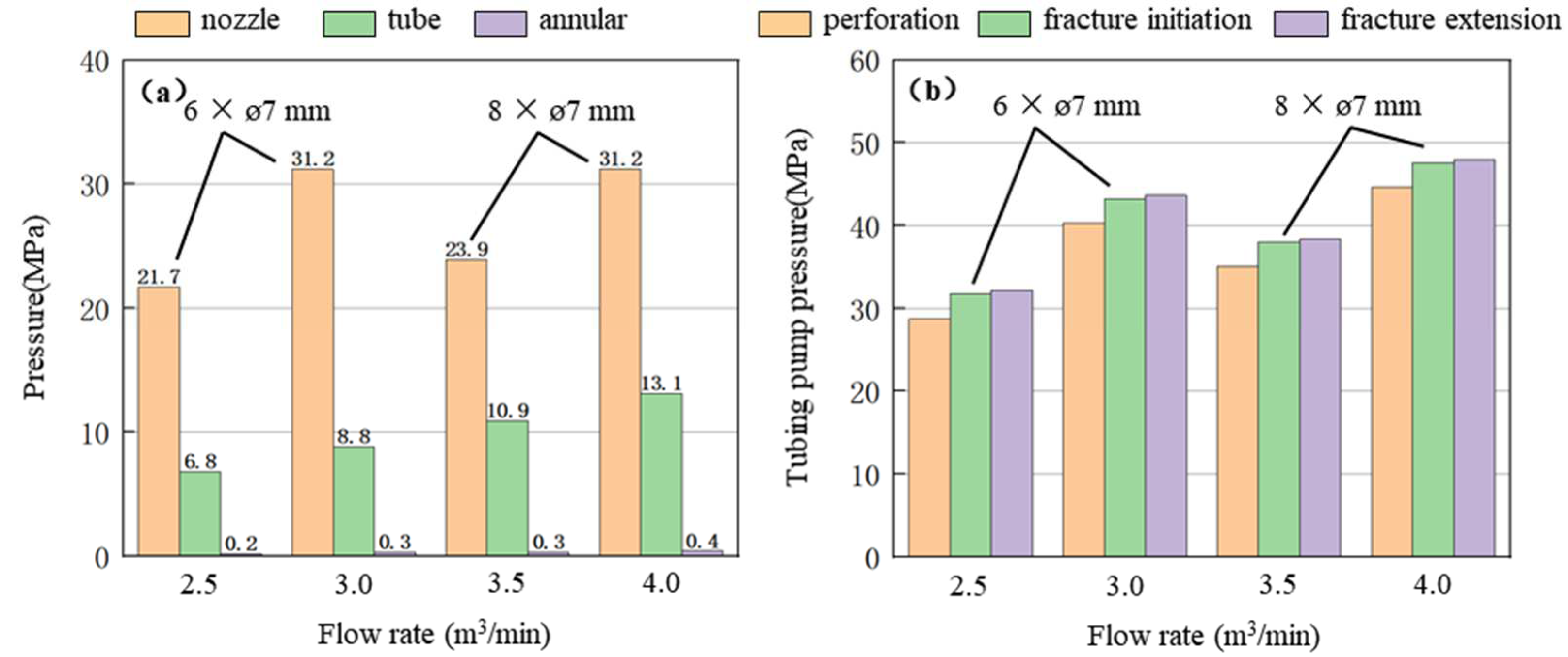
Figure 8a shows a comparison of the three tubing pump pressure components affected by pumping rate. When the pumping rate is 4.0 m3/min, the flow friction of the annular is 0.4 MPa. Compared with the onshore 5–1/2 inch casing, the offshore 9–5/8 inch casing has a much larger annular flow area, so the flow friction of the annular is negligible. At these four flow rates, the injection drop is at least 2.2 times the flow friction of the tubing. Injection drop accounts for more than 62% of the tubing pump pressure, and optimizing the nozzle combination can significantly reduce the tubing pump pressure. Figure 8b shows that all cases of hydra-jet fracturing satisfy the tubing pressure limit, which is below 56 MPa.

4.3. Operation and Requirements

Close the BOP and the four-way annular injection wing valve. Pump the low flow rate. Set the tubing flow rate to 0.5–1.0 m3/min. Fill the tubing with base fluid. Drop the valve ball; low feed the ball to block the check valve. After the base fluid is injected into the tubing at 11.0 m3, the design flow rate is increased to 3.0 m3/min. If the tubing pressure reaches 40.0–42.0 MPa, it indicates that the valve ball is in place and the following steps are carried out. If this pressure is not reached, continue to lower it to 3.0 m3, increase the design flow rate to 3.0 m3/min, and again judge whether the valve ball is in place. Increase tubing flow rate to 3.0 m3/min. Begin sand mixing with 20/40 mesh ceramic particles/sand ratio of 7%. Ensure the flow rate and sand ratio are stable. Maintain the 7% sand ratio and perforate for 3.0 min. Reduce sand ratio to 5%, maintain 3.0 m3/min flow rate, and continue perforating for 7.0 min. Stop adding sand, maintain the flow rate of the tubing, and pump gel to replace the ceramic in the tubing. Reduce the tubing flow rate to 1.0 m3/min, slowly close the annular return valve, and open the annular injection valve. Increase tubing flow rate to 3.0 m3/min. Start the annulus injection at a pressure not greater than the maximum design annulus pressure. In the first stage, the calculated value is 7 MPa. In the second and third stages, the maximum annulus pressure shall be determined according to the pump stop pressure in the first stage. Set annulus flow rate to 0.5~1.0 m3/min. Proppant is then pumped in. When the first stage of the fracturing pump injection is completed, stop pumping. When the pressure is reduced to 0.0 MPa, the well is washed. Rotate the string, and drag the string to the next injection point when there is no abnormality. If the string becomes stuck in the sand, reverse circulation should be used.
During the construction process, the construction flow rate and sand ratio should be adjusted according to the construction pressure. The fluid volume is calculated according to the actual running fracturing string. The fluid volume should not exceed 1.5 times the calculated column volume. Annulus pressure should be monitored throughout the fracturing stage. Within the allowable range of casing pressure, the annular flow rate can be appropriately increased. After fracturing is complete, wellbore losses and spills should be observed before the string is drawn up. If the jet gun fails during the fracturing process, the pump should be stopped, and the ball should be thrown to open the slide sleeve of the standby gun for hydraulic jet fracturing.

5. Conclusions

This paper proposed full-scale experiments for the waterjet perforation of unconsolidated sandstone, the waterjet penetration of screen liners and casing, and pumping pressure prediction. The results verified that multistage hydra-jet fracturing is a robust technology that can be to create multiple fractures in offshore unconsolidated sandstone. The study can be concluded as follows:
(1)
The abrasive water jet is capable of perforating the screen-casing in less than one minute with an over 10 mm diameter hole. The water jet perforates a deep and slim hole in unconsolidated sandstone by using less than 20 MPa pumping pressure. Recommended perforating parameters include: maintain 7% sand ratio and perforate for 3.0 min, reduce sand ratio to 5%, maintain 3.0 m3/min flow rate, and continue perforating for 7.0 min.
(2)
Nozzle pressure drop accounts for more than 62% of the tubing pump pressure. Optimizing the nozzle combination can significantly reduce the pump pressure. The recommended nozzle combinations for different fracturing flow rates are 8 × 6 mm or 6 × 7 mm for 2.5 m3/min and 3.0 m3/min, and 8 × 7 mm for 3.5 m3/min and 4.0 m3/min.
(3)
To avoid the sand sticking issue, a one-trip-multistage jet fracturing process is recommended for use in horizontal wells in offshore unconsolidated sandstone reservoirs.

Author Contributions

Writing—original draft, P.X.; Writing—review and editing, M.S.; Project administration, Y.L., L.Z., J.Z. and X.L. All authors have read and agreed to the published version of the manuscript.

Funding

This work was financially supported by the CNOOC Ltd. Scientific Research Project (No. YXKY-2021-TJ-02).

Data Availability Statement

Data are contained within the article.

Conflicts of Interest

The authors declare no conflict of interest.

References

  1. Yan, C.; Chen, Y.; Chen, T.; Cheng, Y.; Yan, X. Experimental Study of Hydraulic Fracturing for Unconsolidated Reservoirs. Rock Mech. Rock Eng. 2022, 55, 3399–3424. [Google Scholar] [CrossRef]
  2. Monus, F.L.; Broussard, F.W.; Ayoub, J.A.; Norman, W.D. Fracturing unconsolidated sand formations offshore Gulf of Mexico. In Proceedings of the SPE Annual Technical Conference and Exhibition, Washington, DC, USA, 4–7 October 1992. [Google Scholar]
  3. Molenaar, M.M.; Cox, B.E. Field cases of hydraulic fracture stimulation diagnostics using fiber optic distributed acoustic sensing (DAS) measurements and Analyses. In Proceedings of the SPE Unconventional Gas Conference and Exhibition, Muscat, Oman, 28–30 January 2013. [Google Scholar]
  4. Sheng, M.; Huang, Z.-W.; Tian, S.-C.; Zhang, Y.; Gao, S.-W.; Jia, Y.-P. CFD analysis and field observation of tool erosion caused by abrasive waterjet fracturing. Pet. Sci. 2020, 17, 701–711. [Google Scholar] [CrossRef]
  5. Surjaatmadja, J.B.; Bezanson, J.; Lindsay, S.; Ventosilla, P.; Rispler, K. New Hydrajet Tool Demonstrates Improved Life for Perforating and Fracturing Applications. In Proceedings of the SPE/ICoTA Coiled Tubing and Well Intervention Conference and Exhibition, The Woodlands, TX, USA, 1–2 April 2008. [Google Scholar]
  6. Huang, Z.; Li, G.; Tian, S.; Song, X.; Sheng, M.; Shah, S. Abrasive Water Jet Perforation and Multi-Stage Fracturing; Gulf Professional Publishing: Oxford, UK, 2017. [Google Scholar]
  7. Surjaatmadja, J.B.; Willett, R.; McDaniel, B.; Rosolen, M.A.; Franco, M.L.; dos Santos, F.C.R.; Fernandes, P.D.; Carneiro, F.A.; De Lima, B.B.; Cortes, M. Hydrajet-fracturing stimulation process proves effective for offshore brazil horizontal wells. In Proceedings of the SPE Asia Pacific Oil and Gas Conference and Exhibition, Richardson, TX, USA, 18–20 October 2004. [Google Scholar]
  8. Rodrigues, V.F.; Neumann, L.F.; Rosolen, M.A.; Fernandes, P.D.; Lima, C.; Surjaatmadja, J.B.; Gonzalez, C.M.; Carneiro, F. First Implementation of Hydrajet Fracture Acidizing in Deepwater Offshore Brazil Fields. In Proceedings of the SPE European Formation Damage Conference, Sheveningen, The Netherlands, 25–27 May 2005. [Google Scholar]
  9. McDaniel, B.W.; Surjaatmadja, J.B.; East, L.E. Use of hydrajet perforating to improve fracturing success sees global expansion. In Proceedings of the CIPC/SPE Gas Technology Symposium 2008 Joint Conference, Calgary, AB, Canada, 16–19 June 2008. [Google Scholar]
  10. Fu, J.; Ma, Y.; Zhang, M.; Ma, C.; Liu, Z.; Zhou, S.; He, L.; Feng, L. First Offshore Hydraulic-Jet-Fracturing Multizone Completion Application Case Study: Challenges and Lessons Learned in the Bozhong Oil Field, Bohai Bay, China. In Proceedings of the SPE Asia Pacific Oil & Gas Conference and Exhibition, Virtual, 17–19 November 2020. [Google Scholar]
  11. Li, S.; Yi, X.; Kuang, M.; Xie, Y.; Zhang, Z.; Wang, X.; Gao, Y. Integrated Technologies in the Floating Hydraulic Fracturing for Unconventional Offshore Reservoir. In Proceedings of the Offshore Technology Conference, Houston, TX, USA, 4–7 May 2020. [Google Scholar]
  12. Diaz, O.G.; Luna, G.G.; Liao, Z.; Axinte, D. The new challenges of machining Ceramic Matrix Composites (CMCs): Review of surface integrity. Int. J. Mach. Tools Manuf. 2019, 139, 24–36. [Google Scholar] [CrossRef]
  13. Kamel, A.H. RJD: A cost effective frackless solution for production enhancement in marginal fields. In Proceedings of the SPE Eastern Regional Meeting, Canton, OH, USA, 13–15 September 2016. [Google Scholar]
  14. Huang, M.; Wu, L.; Ning, F.; Wang, J.; Dou, X.; Zhang, L.; Liu, T.; Jiang, G. Research progress in natural gas hydrate reservoir stimulation. Nat. Gas Ind. B 2023, 10, 114–129. [Google Scholar] [CrossRef]
  15. Bi, G.; Wang, X.; Han, F.; Wu, J.; Yuan, P.; Fu, S.; Ma, Y. Study on the Mechanism of High-Efficiency Rock Breaking by Hydraulic Jet Based on Explicit Dynamics. Processes 2023, 11, 2165. [Google Scholar] [CrossRef]
  16. Meese, C.; Mullen, M.; Barree, R. Offshore Hydraulic Fracturing Technique. J. Pet. Technol. 1994, 46, 226–229. [Google Scholar] [CrossRef]
  17. Pandey, V.J.; Burton, R.C.; Nozaki, M. Evolution of Frac-Pack Design and Completion Procedures for High Permeability Gas Wells in Subsea Service. In Proceedings of the SPE Hydraulic Fracturing Technology Conference, Richardson, TX, USA, 4–6 February 2014. [Google Scholar]
  18. Shi, X.; Zhang, W.; Xu, H.; Xiao, C.; Jiang, S. Experimental study of hydraulic fracture initiation and propagation in unconsolidated sand with the injection of temporary plugging agent. J. Pet. Sci. Eng. 2019, 190, 106813. [Google Scholar] [CrossRef]
  19. Di, J.; Zhao, X.; Lv, J.; Rao, L. Application of Abrasive Waterjet Technology for Large and Multi-Casing Cutting. In Proceedings of the SPE/IADC Middle East Drilling Technology Conference and Exhibition, Abu Dhabi, United Arab Emirates, 23–25 May 2023. [Google Scholar]
  20. Surjaatmadja, J.B.; Bailey, A.; Sierra, S. HydraJet Testing Under Deep Well Conditions Defines New Requirements for Hard-Rock Perforating. In Proceedings of the SPE Rocky Mountain Petroleum Technology Conference, Denver, CO, USA, 14–16 April 2009. [Google Scholar]
  21. Pan, Y.; Zhai, S.; Meng, X.; Pei, K.; Huo, F. Study on the Fracturing of Rock by High-Speed Water Jet Impact. Processes 2022, 11, 114. [Google Scholar] [CrossRef]
  22. Shaykamalov, R.; Gaponov, M.; Mukhametshin, M.; Bildanov, V.; Katermin, A.; Bashirov, I. Multistage horizontal wells refracturing by means of abrasive jet perforation+ frac technology. In Proceedings of the SPE Symposium: Hydraulic Fracturing in Russia: Experience and Prospects, Richardson, TX, USA, 22–24 September 2020. [Google Scholar]
  23. Lee, K.K.; Chen, J.L.; Liu, Y.J.; Li, Y.K.; Zeng, X.Z.; Zhou, B.; Hu, G.; Wang, S.L. Application of Pin-Point Sand Jet Perforating Annular Fracturing in Multiple Coal Seams Unleashing Clean Energy in Southwest China. In Proceedings of the SPE Annual Technical Conference and Exhibition, Richardson, TX, USA, 9–11 October 2017. [Google Scholar]
  24. Zhu, D.; Wang, Y.; Cui, M.; Zhou, F.; Wang, Y.; Liang, C.; Zou, H.; Yao, F. Acid System and Stimulation Efficiency of Multistage Acid Fracturing in Porous Carbonate Reservoirs. Processes 2022, 10, 1883. [Google Scholar] [CrossRef]
  25. Li, G.; Sheng, M.; Tian, S.; Huang, Z.; Li, Y.; Yuan, X. Multistage hydraulic jet acid fracturing technique for horizontal wells. Pet. Explor. Dev. 2012, 39, 107–112. [Google Scholar] [CrossRef]
  26. Li, G.; Sheng, M.; Tian, S.; Huang, Z.; Li, Y.; Yuan, X. New technique: Hydra-jet fracturing for effectiveness of multi-zone acid fracturing on an ultra deep horizontal well and case study. In Proceedings of the IADC/SPE Asia Pacific Drilling Technology Conference and Exhibition, Tianjin, China, 9–11 July 2012. [Google Scholar]
  27. Sheng, M.; Li, G.; Huang, Z.; Tian, S.; Qu, H. Experimental study on hydraulic isolation mechanism during hydra-jet fracturing. Exp. Therm. Fluid Sci. 2012, 44, 722–726. [Google Scholar] [CrossRef]
  28. Huang, Z.; Li, G.; Tian, S.; Shen, Z.; Luo, H. Mechanism and numerical simulation of pressure stagnation during water jetting perforation. Pet. Sci. 2008, 5, 52–55. [Google Scholar] [CrossRef]
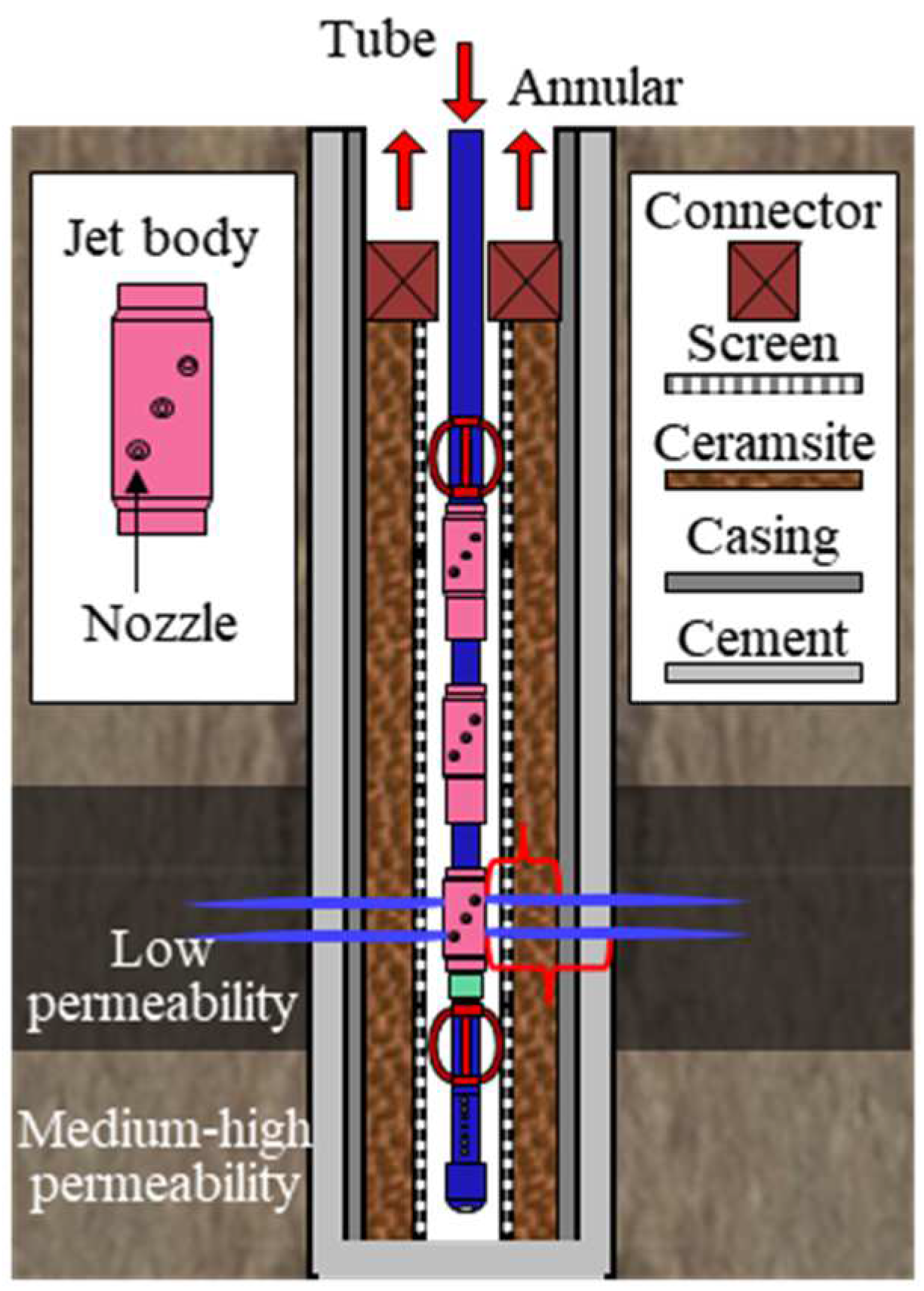
Figure 1. Illustration of abrasive waterjet perforation and multistage fracturing in unconsolidated sandstones.
Processes 11 03137 g001
Figure 2. Abrasive waterjet impact on screener-casing. (a) Schematic diagram of the experimental method. (b) Experimental facility. (c) Screener after experiment. (d) Gravel pack after experiment. (e) Casing after experiment. (f) Cement after experiment.
Processes 11 03137 g002
Figure 3. The process of abrasive water jet penetrating screen-casing at different jet rates.
Processes 11 03137 g003
Figure 4. Waterjet perforation experiments. (a) Schematic diagram of the experimental method. (b) Unconsolidated sandstone after experiment. (c) Red sandstone after experiment.
Processes 11 03137 g004
Figure 5. Comparison of jet impact on unconsolidated sandstone and red sandstone. (a) Rock breaking depth. (b) Rock breaking diameter. (c) CT scanning of #1 unconsolidated sandstone perforated by water jet.
Processes 11 03137 g005
Figure 6. Illustration of bottom-hole tool and the optimization of waterjet nozzles. (a) Key parameters of waterjet nozzles. (b) Correlations between pumping rate and waterjet velocity (c) Nozzle distance between two layers and its effects on perforating holes.
Processes 11 03137 g006
Figure 7. Bottom-hole tool string for offshore hydra-jet fracturing.
Processes 11 03137 g007
Figure 8. Pump pressure distribution and change throughout the jet fracturing process under different fracturing flow rates. (a) Comparison of pump pressure components affected by flow rate. (b) Comparison of pump pressure at different stages of jet fracturing.
Processes 11 03137 g008
Table 1. Comparison of field and experimental materials.
MaterialsField ParametersExperimental Parameters
Nozzleconical, outlet diameter 5–7 mmconical, outlet diameter 5 mm
Fluidfracturing fluidwater
Abrasivequartz sand, garnet, ceramisite, 20/40 meshceramisite, 20/40 mesh, volume density of 1620 kg/m3, apparent density of 2950 kg/m3, compressive strength of 69 MPa
Sand concentration6–8% Volume ratio5% Volume ratio
Screener139.7 mm wire-wound screener, base pipe of 25.3 kg/m and N80 rank139.7 mm wire-wound screener nipple, base pipe of 25.3 kg/m and N80 rank, side window for nozzle
Gravel packceramist, 20/40 mesh, thickness 37 mmceramist, 20/40 mesh, thickness 30 mm
Casing244.5 mm casing, 86.9 kg/m and N80 rank244.5 mm casing, 86.9 kg/m and N80 rank
CementPortland cement, Water-cement ratio 0.44, thickness 33 mmPortland cement, Water-cement ratio 0.44, thickness 30 mm
Table 2. Comparison of physical parameters between unconsolidated sandstone and red sandstone.
Physical ParametersUnconsolidated SandstoneRed Sandstone
Density, kg/m319902230
Porosity, %21.917.8
Permeability, mD56.332.6
Elasticity modulus, GPa0.298.71
Poisson ratio0.340.38
uniaxial compressive strength, MPa2.739.5
Table 3. The calculation parameters of cases.
ClassificationNameParameter
GeologyVertical depth, m2000
Fracture initiation pressure gradient, MPa/m0.0185
Fracture extension gradient, MPa/m0.0150
WellOblique depth, m2500
Inside diameter of casing, mm224.4
ToolNozzle combination6 × ø7 mm/8 × ø7 mm
Inside diameter of tubing, mm76
Outside diameter of tubing, mm88.9
ProcessPumping rate, m3/min2.5, 3.0 3.5, 4.0
Fracturing fluid density, kg/m31050
Fracturing fluid viscosity, mPa·s1.12
Flow coefficient0.22
Disclaimer/Publisher’s Note: The statements, opinions and data contained in all publications are solely those of the individual author(s) and contributor(s) and not of MDPI and/or the editor(s). MDPI and/or the editor(s) disclaim responsibility for any injury to people or property resulting from any ideas, methods, instructions or products referred to in the content.