
Compressed Air Energy Storage (CAES) and Liquid Air Energy Storage (LAES) Technologies—A Comparison Review of Technology Possibilities


Abstract
:1. Introduction
2. Technology Basic Principle Overview
2.1. CAES Basic Principle
2.2. LAES Basic Principle
3. Design Options and Possibilities
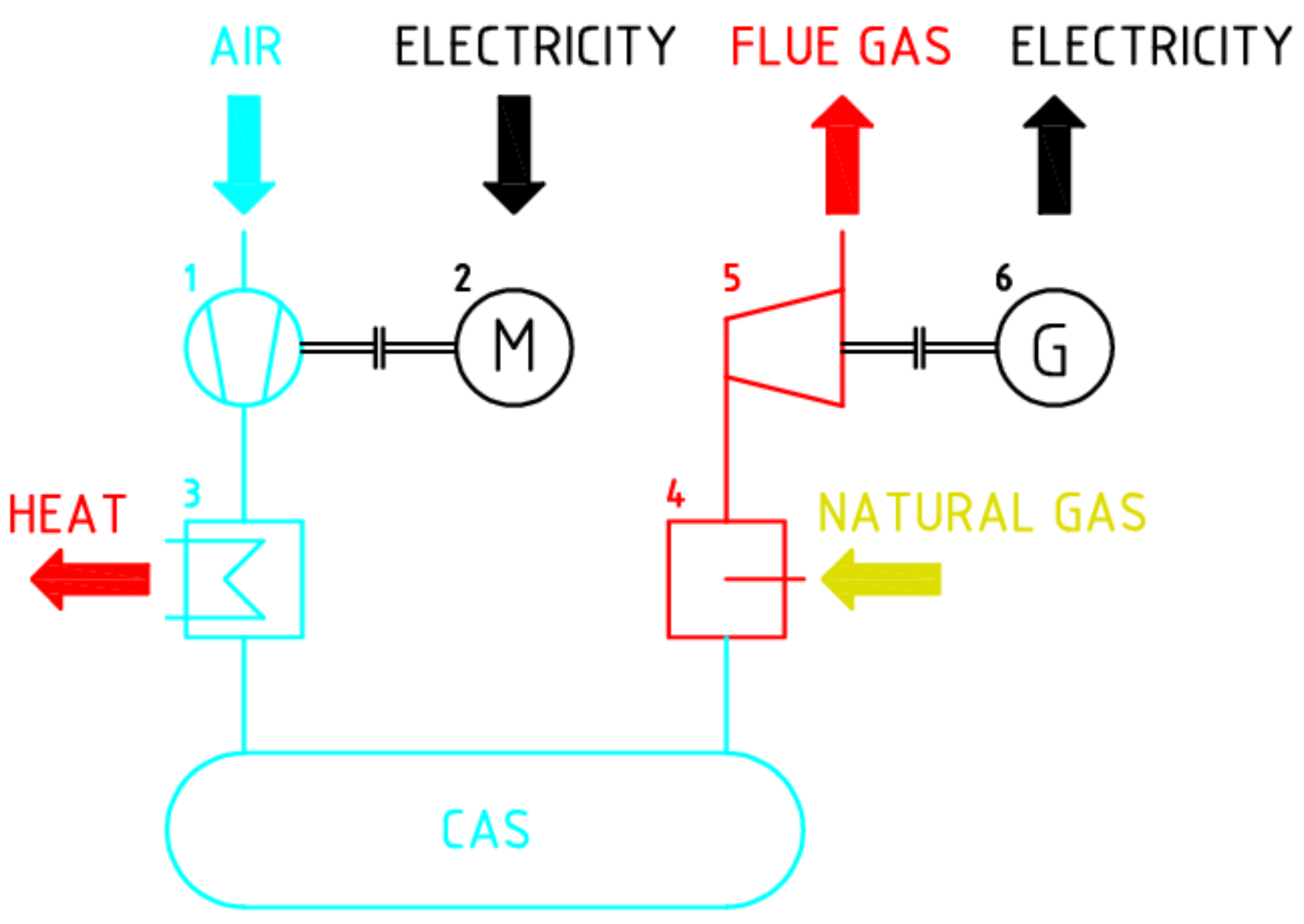
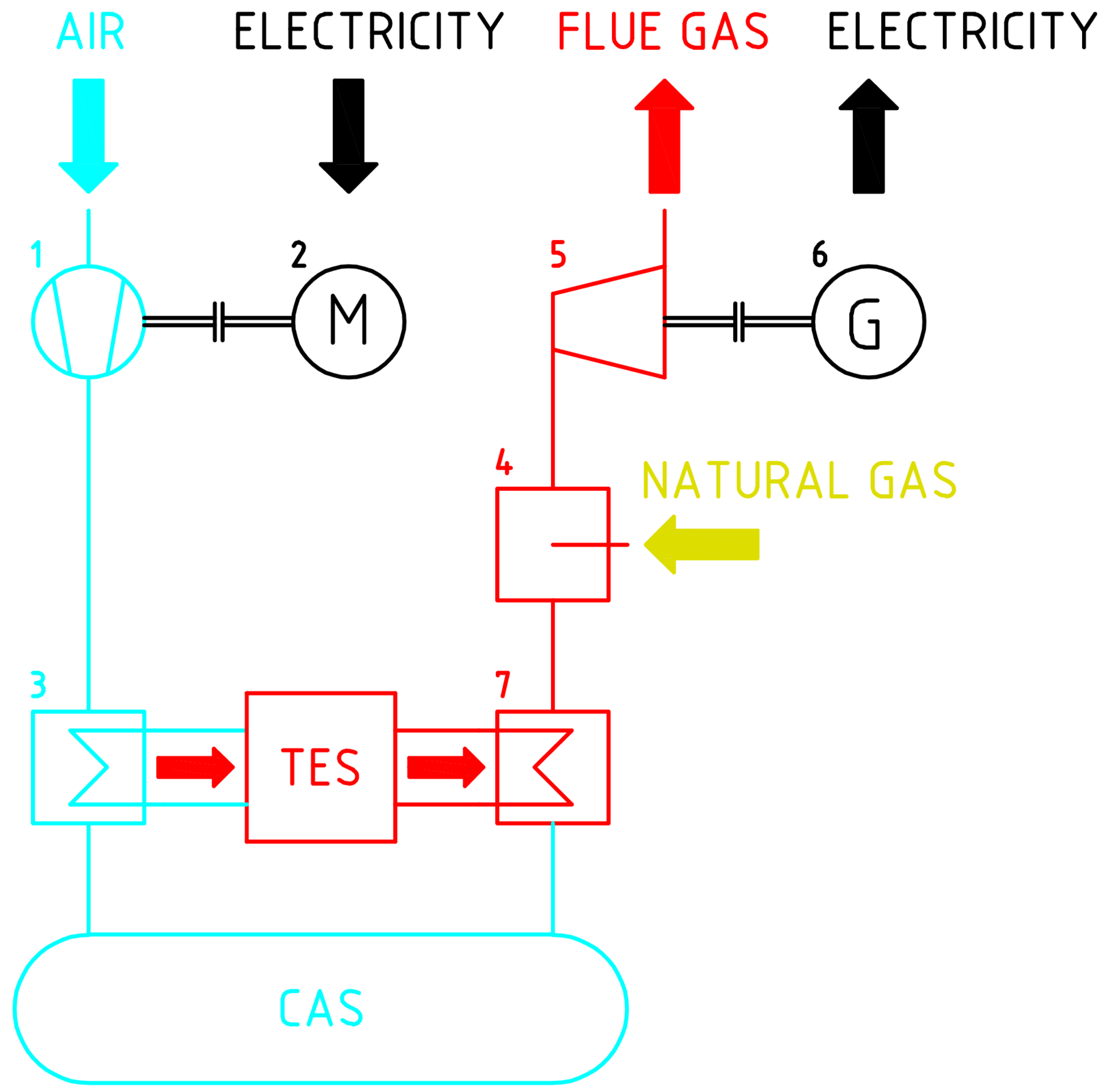
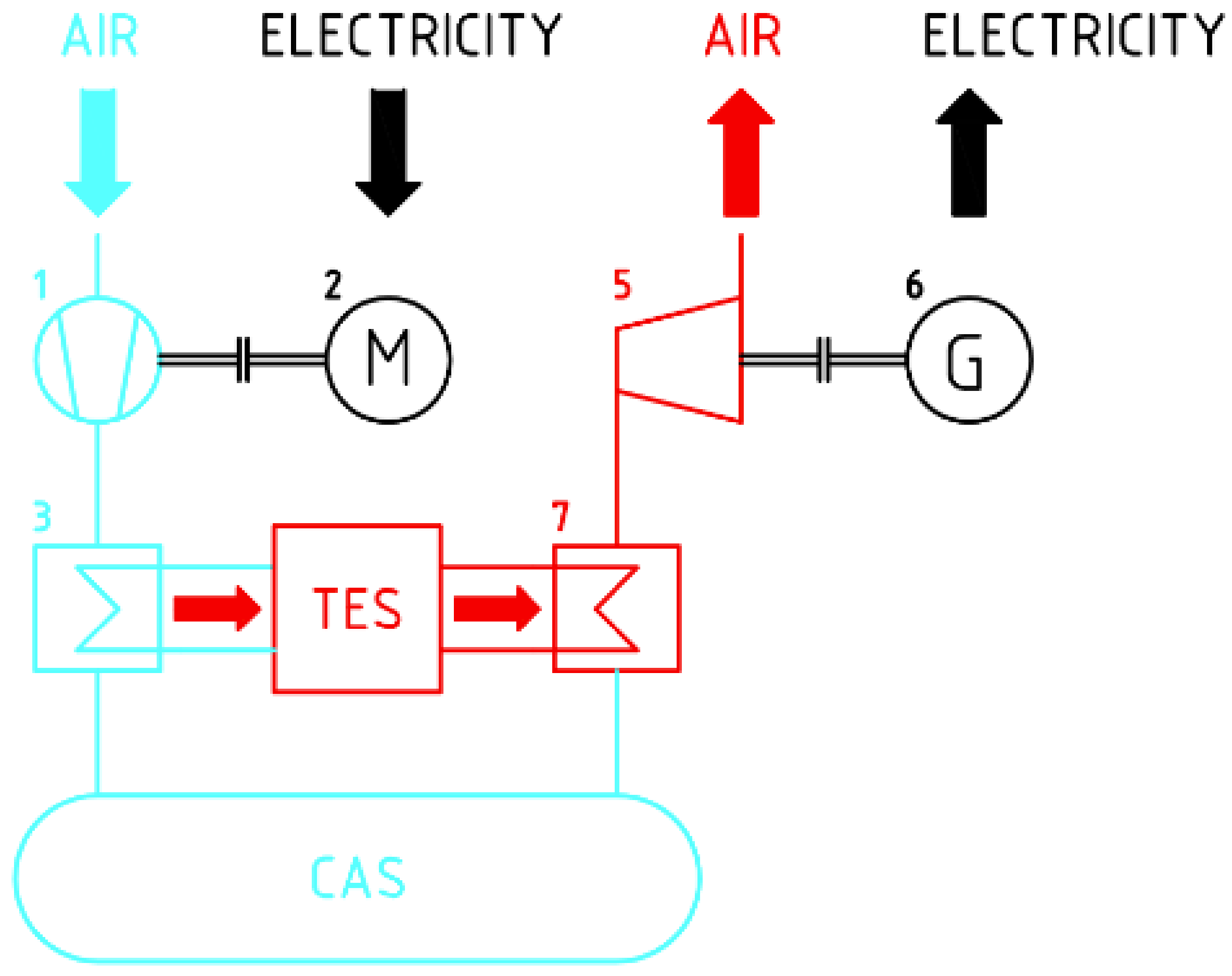
3.1. CAES Design
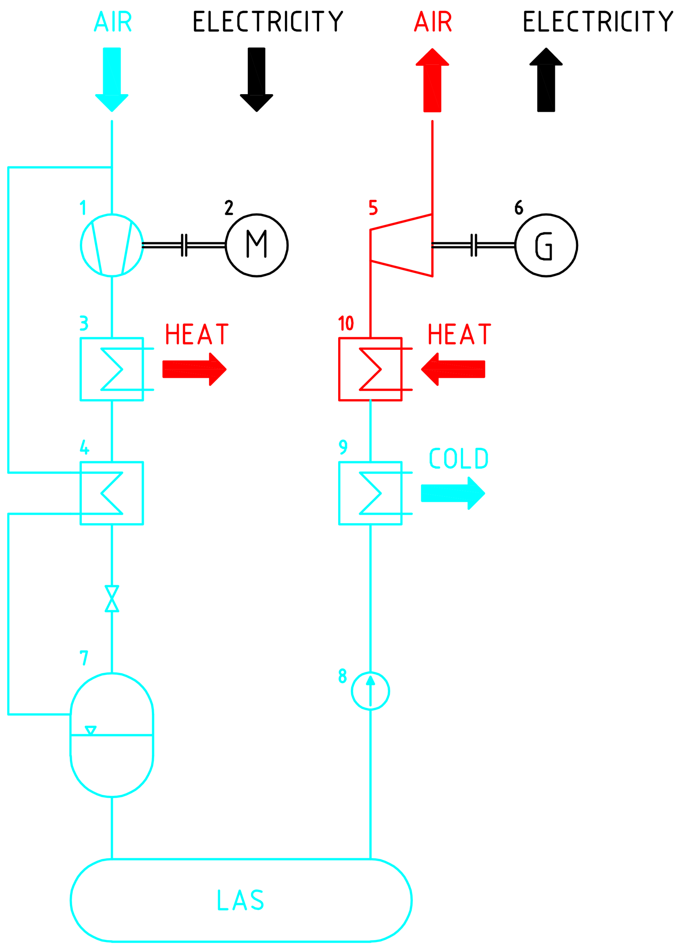
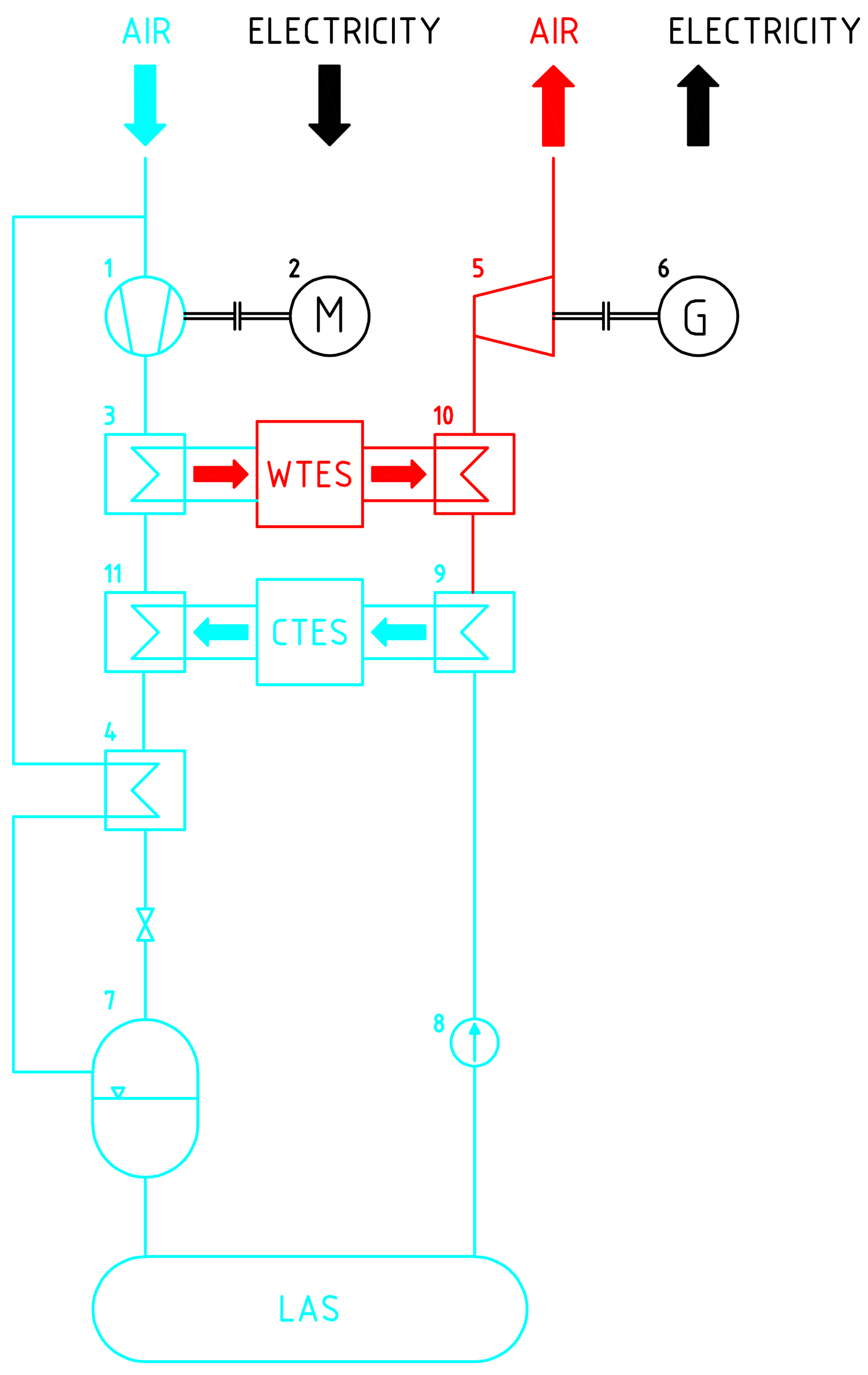
3.2. LAES Design
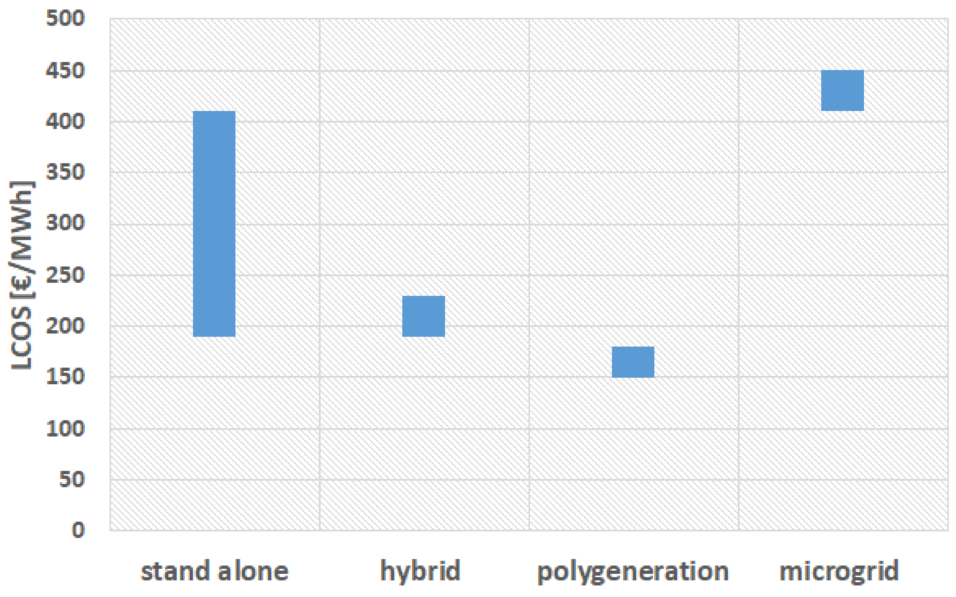
4. Technology Perspectives and Differences
- Standalone configuration: This design represents a single-purpose facility solely focused on the storage of electric energy. Typically, these facilities have large capacities, often reaching hundreds of MWh.
- Microgrid configuration: This configuration involves systems with smaller energy supply capacities that are connected in close proximity to the end user.
5. Technology SWOT Analysis
5.1. CAES Technology

| Strengths | Weaknesses |
|---|---|
|
|
| Opportunities | Threats |
|
|
5.2. LAES Technology
| Strengths | Weaknesses |
|---|---|
|
|
| Opportunities | Threats |
|
|
6. Design Indicators
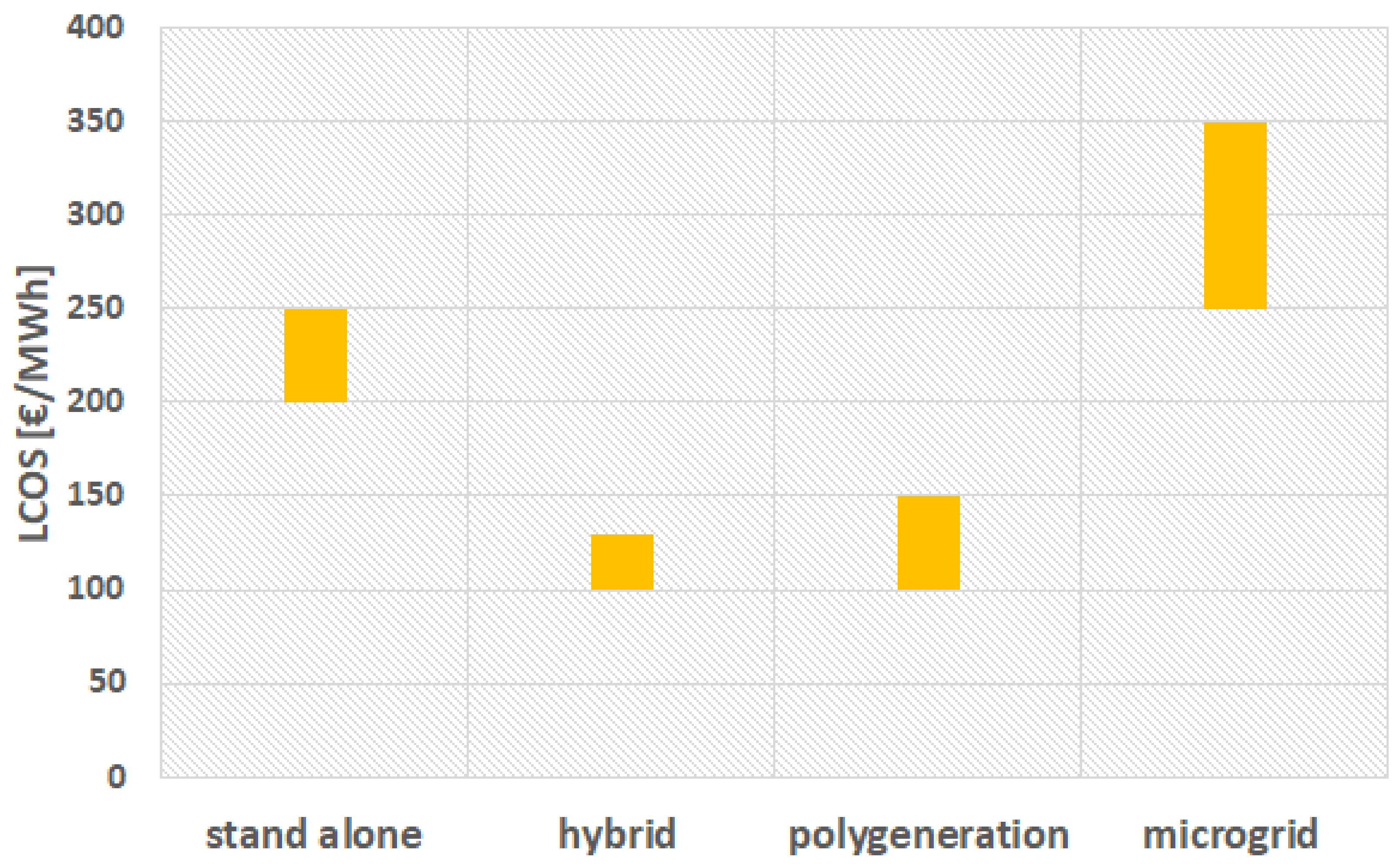
7. Economic Indicator
8. Conclusions
- Development of thermal energy storage technologies which will be cheaper, with fast charging and discharging.
- Development technologies for high-grade cold storage (LAES).
- Searching new locations with suitable geological conditions (CAES).
- Development of effective technologies for heat exchange between heat storage and other parts of the storage system.
- Development of new integrated technologies with involved CAES or LAES.
- Development of new operation models of CAES and LEAE operation in grits with renewables.
- Intensification of operational parameters of systems components (compressors, heat exchangers and atd.) of round trip efficiency improvement.
9. Literature Review
Author Contributions
Funding
Data Availability Statement
Conflicts of Interest
Abbreviations
| ARC | Absorption Refrigeration Cycle |
| CAES | Compressed Air Energy an Storage |
| AA-CAES | Advanced Adiabatic Compressed Air Energy Storage |
| A-CAES | Adiabatic Compressed Air Energy Storage |
| D-CAES | Diabatic Compressed Air Energy Storage |
| CAS | Compressed Air Storage |
| CHP | Combined Heat and Power |
| CTES | Cold Thermal Energy Storage |
| LAES | Liquid Air Energy Storage |
| LAS | Liquid Air Storage |
| LCOE | Levelized Cost of Electricity |
| LCOS | Levelized Cost of Storage |
| LNG | Liquefied Natural Gas |
| RTE | Round Trip Efficiency |
| TES | Thermal Energy Storage |
| ORC | Organic Rankine Cycle |
| UCAES | Underwater Compressed Air Energy Storage |
| WTES | Warm Thermal Energy Storage |
References
- Tan, K.M.; Babu, T.S.; Ramachandaramurthy, V.K.; Kasinathan, P.; Solanki, S.G.; Raveendran, S.K. Empowering smart grid: A comprehensive review of energy storage technology and application with renewable energy integration. J. Energy Storage 2021, 39, 102591. [Google Scholar] [CrossRef]
- Leonard, M.D.; Michaelides, E.E.; Michaelides, D.N. Energy storage needs for the substitution of fossil fuel power plants with renewables. Renew. Energy 2020, 145, 951–962. [Google Scholar] [CrossRef]
- Al kez, D.; Foley, A.M.; McIlwaine, N.; Morrow, D.J.; Hayes, B.P.; Zehir, M.A.; Mehigan, L.; Papari, B.; Edrington, C.S.; Baran, M. A critical evaluation of grid stability and codes, energy storage and smart loads in power systems with wind generation. Energy 2020, 205, 117671. [Google Scholar] [CrossRef]
- IEA. Technology Roadmap—Energy Storage; Technical Report; IEA: Paris, France, 2014. [Google Scholar]
- Guney, M.S.; Tepe, Y. Classification and assessment of energy storage systems. Renew. Sustain. Energy Rev. 2017, 75, 1187–1197. [Google Scholar] [CrossRef]
- Vecchi, A.; Li, Y.; Ding, Y.; Mancarella, P.; Sciacovelli, A. Liquid air energy storage (LAES): A review on technology state-of-the-art, integration pathways and future perspectives. Adv. Appl. Energy 2021, 3, 100047. [Google Scholar] [CrossRef]
- Steinmann, W.D. Thermo-mechanical concepts for bulk energy storage. Renew. Sustain. Energy Rev. 2017, 75, 205–219. [Google Scholar] [CrossRef]
- Dumont, O.; Frate, G.F.; Pillai, A.; Lecompte, S.; Paepe, M.D.; Lemort, V. Carnot battery technology: A state-of-the-art review. J. Energy Storage 2020, 32, 101756. [Google Scholar] [CrossRef]
- Zhou, Q.; Du, D.; Lu, C.; He, Q.; Liu, W. A review of thermal energy storage in compressed air energy storage system. Energy 2019, 188, 115993. [Google Scholar] [CrossRef]
- Borri, E.; Tafone, A.; Romagnoli, A.; Comodi, G. A review on liquid air energy storage: History, state of the art and recent developments. Renew. Sustain. Energy Rev. 2021, 137, 110572. [Google Scholar] [CrossRef]
- Bazdar, E.; Sameti, M.; Nasiri, F.; Haghighat, F. Compressed air energy storage in integrated energy systems: A review. Renew. Sustain. Energy Rev. 2022, 167, 112701. [Google Scholar] [CrossRef]
- Budt, M.; Wolf, D.; Span, R.; Yan, J. A review on compressed air energy storage: Basic principles, past milestones and recent developments. Appl. Energy 2016, 170, 250–268. [Google Scholar] [CrossRef]
- He, Y.; Chen, H.; Xu, Y.; Deng, J. Compression performance optimization considering variable charge pressure in an adiabatic compressed air energy storage system. Energy 2018, 165, 349–359. [Google Scholar] [CrossRef]
- He, W.; Wang, J. Optimal selection of air expansion machine in Compressed Air Energy Storage: A review. Renew. Sustain. Energy Rev. 2018, 87, 77–95. [Google Scholar] [CrossRef]
- Han, Y.; Cui, H.; Ma, H.; Chen, J.; Liu, N. Temperature and pressure variations in salt compressed air energy storage (CAES) caverns considering the air flow in the underground wellbore. J. Energy Storage 2022, 52, 104846. [Google Scholar] [CrossRef]
- Jafarizadeh, H.; Soltani, M.; Nathwani, J. Assessment of the Huntorf compressed air energy storage plant performance under enhanced modifications. Energy Convers. Manag. 2020, 209, 112662. [Google Scholar] [CrossRef]
- Borri, E.; Tafone, A.; Comodi, G.; Romagnoli, A.; Cabeza, L.F. Compressed Air Energy Storage—An Overview of Research Trends and Gaps through a Bibliometric Analysis. Energies 2022, 15, 7692. [Google Scholar] [CrossRef]
- Chen, L.; Wang, Y.; Xie, M.; Ye, K.; Mohtaram, S. Energy and exergy analysis of two modified adiabatic compressed air energy storage (A-CAES) system for cogeneration of power and cooling on the base of volatile fluid. J. Energy Storage 2021, 42, 103009. [Google Scholar] [CrossRef]
- O’Callaghan, O.; Donnellan, P. Liquid air energy storage systems: A review. Renew. Sustain. Energy Rev. 2021, 146, 111113. [Google Scholar] [CrossRef]
- Dzido, A.; Krawczyk, P.; Wołowicz, M.; Badyda, K. Comparison of advanced air liquefaction systems in Liquid Air Energy Storage applications. Renew. Energy 2022, 184, 727–739. [Google Scholar] [CrossRef]
- Li, J.; Li, X.; Yan, P.; Zhou, G.; Liu, J.; Yu, D. Thermodynamics, flexibility and techno-economics assessment of a novel integration of coal-fired combined heating and power generation unit and compressed air energy storage. Appl. Energy 2023, 339, 120924. [Google Scholar] [CrossRef]
- Park, J.H.; Heo, J.Y.; Lee, J.I. Techno-economic study of nuclear integrated liquid air energy storage system. Energy Convers. Manag. 2022, 251, 114937. [Google Scholar] [CrossRef]
- Lu, Y.; Xu, J.; Chen, X.; Tian, Y.; Zhang, H. Design and thermodynamic analysis of an advanced liquid air energy storage system coupled with LNG cold energy, ORCs and natural resources. Energy 2023, 275, 127538. [Google Scholar] [CrossRef]
- Peng, X.; She, X.; Li, C.; Luo, Y.; Zhang, T.; Li, Y.; Ding, Y. Liquid air energy storage flexibly coupled with LNG regasification for improving air liquefaction. Appl. Energy 2019, 250, 1190–1201. [Google Scholar] [CrossRef]
- Alirahmi, S.M.; Mousavi, S.B.; Razmi, A.R.; Ahmadi, P. A comprehensive techno-economic analysis and multi-criteria optimization of a compressed air energy storage (CAES) hybridized with solar and desalination units. Energy Convers. Manag. 2021, 236, 114053. [Google Scholar] [CrossRef]
- Razmi, A.; Soltani, M.; Tayefeh, M.; Torabi, M.; Dusseault, M.B. Thermodynamic analysis of compressed air energy storage (CAES) hybridized with a multi-effect desalination (MED) system. Energy Convers. Manag. 2019, 199, 112047. [Google Scholar] [CrossRef]
- Venkataramani, G.; Parankusam, P.; Ramalingam, V.; Wang, J. A review on compressed air energy storage—A pathway for smart grid and polygeneration. Renew. Sustain. Energy Rev. 2016, 62, 895–907. [Google Scholar] [CrossRef]
- Crotogino, F.; Mohmeyer, K.U.; Scharf, R. Huntorf CAES: More than 20 Years of Successful Operation. In Proceedings of the Solution Mining Research Institute (SMRI) Spring Meeting, Orlando, FL, USA, 15–18 April 2001; pp. 351–357. [Google Scholar]
- Olabi, A.G.; Wilberforce, T.; Ramadan, M.; Abdelkareem, M.A.; Alami, A.H. Compressed air energy storage systems: Components and operating parameters—A review. J. Energy Storage 2021, 34, 102000. [Google Scholar] [CrossRef]
- Neu, T.; Subrenat, A. Experimental investigation of internal air flow during slow piston compression into isothermal compressed air energy storage. J. Energy Storage 2021, 38, 102532. [Google Scholar] [CrossRef]
- Xu, W.; Du, Z.; Wang, X.; Cai, M.; Jia, G.; Shi, Y. Isothermal piston gas compression for compressed air energy storage. Int. J. Heat Mass Transf. 2020, 155, 119779. [Google Scholar] [CrossRef]
- Neu, T.; Solliec, C.; dos Santos Piccoli, B. Experimental study of convective heat transfer during liquid piston compressions applied to near isothermal underwater compressed-air energy storage. J. Energy Storage 2020, 32, 101827. [Google Scholar] [CrossRef]
- Hu, S.; Xu, W.; Cai, M.; Jia, G. Energy efficiency and power density analysis of a tube array liquid piston air compressor/expander for compressed air energy storage. J. Energy Storage 2022, 55, 105674. [Google Scholar] [CrossRef]
- Bennett, J.A.; Fitts, J.P.; Clarens, A.F. Compressed air energy storage capacity of offshore saline aquifers using isothermal cycling. Appl. Energy 2022, 325, 119830. [Google Scholar] [CrossRef]
- Arellano-Prieto, Y.; Chavez-Panduro, E.; Rossi, P.S.; Finotti, F. Energy Storage Solutions for Offshore Applications. Energies 2022, 15, 6153. [Google Scholar] [CrossRef]
- Liu, Z.; Liu, X.; Yang, S.; Hooman, K.; Yang, X. Assessment evaluation of a trigeneration system incorporated with an underwater compressed air energy storage. Appl. Energy 2021, 303, 117648. [Google Scholar] [CrossRef]
- Briffa, L.J.; Cutajar, C.; Sant, T.; Buhagiar, D. Numerical Modeling of the Thermal Behavior of Subsea Hydro-Pneumatic Energy Storage Accumulators Using Air and CO2. Energies 2022, 15, 8706. [Google Scholar] [CrossRef]
- Wang, S.; Zhang, X.; Yang, L.; Zhou, Y.; Wang, J. Experimental study of compressed air energy storage system with thermal energy storage. Energy 2016, 103, 182–191. [Google Scholar] [CrossRef]
- Zhang, Y.; Yang, K.; Li, X.; Xu, J. The thermodynamic effect of thermal energy storage on compressed air energy storage system. Renew. Energy 2013, 50, 227–235. [Google Scholar] [CrossRef]
- Barbour, E.; Mignard, D.; Ding, Y.; Li, Y. Adiabatic Compressed Air Energy Storage with packed bed thermal energy storage. Appl. Energy 2015, 155, 804–815. [Google Scholar] [CrossRef]
- Guo, H.; Xu, Y.; Huang, L.; Zhu, Y.; Liang, Q.; Chen, H. Concise analytical solution and optimization of compressed air energy storage systems with thermal storage. Energy 2022, 258, 124773. [Google Scholar] [CrossRef]
- Bartela, Ł.; Ochmann, J.; Waniczek, S.; Lutyński, M.; Smolnik, G.; Rulik, S. Evaluation of the energy potential of an adiabatic compressed air energy storage system based on a novel thermal energy storage system in a post mining shaft. J. Energy Storage 2022, 54, 105282. [Google Scholar] [CrossRef]
- Frate, G.F.; Antonelli, M.; Desideri, U. A novel Pumped Thermal Electricity Storage (PTES) system with thermal integration. Appl. Therm. Eng. 2017, 121, 1051–1058. [Google Scholar] [CrossRef]
- Morgan, R.; Nelmes, S.; Gibson, E.; Brett, G. Liquid air energy storage—Analysis and first results from a pilot scale demonstration plant. Appl. Energy 2015, 137, 845–853. [Google Scholar] [CrossRef]
- Szablowski, L.; Krawczyk, P.; Wolowicz, M. Exergy analysis of adiabatic liquid air energy storage (A-laes) system based on linde–hampson cycle. Energies 2021, 14, 945. [Google Scholar] [CrossRef]
- Mousavi, S.B.; Ahmadi, P.; Adib, M.; Izadi, A. Techno-economic assessment of an efficient liquid air energy storage with ejector refrigeration cycle for peak shaving of renewable energies. Renew. Energy 2023, 214, 96–113. [Google Scholar] [CrossRef]
- Hüttermann, L.; Span, R. Influence of the heat capacity of the storage material on the efficiency of thermal regenerators in liquid air energy storage systems. Energy 2019, 174, 236–245. [Google Scholar] [CrossRef]
- Tafone, A.; Romagnoli, A.; Li, Y.; Borri, E.; Comodi, G. Techno-economic Analysis of a Liquid Air Energy Storage (LAES) for Cooling Application in Hot Climates. Energy Procedia 2017, 105, 4450–4457. [Google Scholar] [CrossRef]
- Kim, J.; Chang, D. Pressurized cryogenic air energy storage for efficiency improvement of liquid air energy storage. Energy Procedia 2019, 158, 5086–5091. [Google Scholar] [CrossRef]
- Sciacovelli, A.; Vecchi, A.; Ding, Y. Liquid air energy storage (LAES) with packed bed cold thermal storage—From component to system level performance through dynamic modelling. Appl. Energy 2017, 190, 84–98. [Google Scholar] [CrossRef]
- Ameel, B.; T’Joen, C.; Kerpel, K.D.; Jaeger, P.D.; Huisseune, H.; Belleghem, M.V.; Paepe, M.D. Thermodynamic analysis of energy storage with a liquid air Rankine cycle. Appl. Therm. Eng. 2013, 52, 130–140. [Google Scholar] [CrossRef]
- Menezes, M.V.P.; Vilasboas, I.F.; Silva, J.A.M.D. Liquid Air Energy Storage System (LAES) Assisted by Cryogenic Air Rankine Cycle (ARC). Energies 2022, 15, 2730. [Google Scholar] [CrossRef]
- He, Q.; Wang, L.; Zhou, Q.; Lu, C.; Du, D.; Liu, W. Thermodynamic analysis and optimization of liquefied air energy storage system. Energy 2019, 173, 162–173. [Google Scholar] [CrossRef]
- Tafone, A.; Ding, Y.; Li, Y.; Xie, C.; Romagnoli, A. Levelised Cost of Storage (LCOS) analysis of liquid air energy storage system integrated with Organic Rankine Cycle. Energy 2020, 198, 117275. [Google Scholar] [CrossRef]
- Tafone, A.; Borri, E.; Comodi, G.; van den Broek, M.; Romagnoli, A. Liquid Air Energy Storage performance enhancement by means of Organic Rankine Cycle and Absorption Chiller. Appl. Energy 2018, 228, 1810–1821. [Google Scholar] [CrossRef]
- Wei, X.; Ban, S.; Shi, X.; Li, P.; Li, Y.; Zhu, S.; Yang, K.; Bai, W.; Yang, C. Carbon and energy storage in salt caverns under the background of carbon neutralization in China. Energy 2023, 272, 127120. [Google Scholar] [CrossRef]
- Xia, C.; Zhou, Y.; Zhou, S.; Zhang, P.; Wang, F. A simplified and unified analytical solution for temperature and pressure variations in compressed air energy storage caverns. Renew. Energy 2015, 74, 718–726. [Google Scholar] [CrossRef]
- Qin, S.; Xia, C.; Zhou, S. Air tightness of compressed air storage energy caverns with polymer sealing layer subjected to various air pressures. J. Rock Mech. Geotech. Eng. 2022, 15, 2105–2116. [Google Scholar] [CrossRef]
- Wang, T.; Yang, C.; Wang, H.; Ding, S.; Daemen, J.J. Debrining prediction of a salt cavern used for compressed air energy storage. Energy 2018, 147, 464–476. [Google Scholar] [CrossRef]
- Wang, X.; Wang, J.; Zhang, Q.; Song, Z.; Liu, X.; Feng, S. Long-term stability analysis and evaluation of salt cavern compressed air energy storage power plant under creep-fatigue interaction. J. Energy Storage 2022, 55, 105843. [Google Scholar] [CrossRef]
- Sarmast, S.; Rouindej, K.; Fraser, R.A.; Dusseault, M.B. Sizing-design method for compressed air energy storage (CAES) systems: A case study based on power grid in Ontario. Energy Convers. Manag. 2023, 277, 116656. [Google Scholar] [CrossRef]
- Karaca, A.E.; Dincer, I.; Nitefor, M. A new renewable energy system integrated with compressed air energy storage and multistage desalination. Energy 2023, 268, 126723. [Google Scholar] [CrossRef]
- Zhao, P.; Zhang, S.; Gou, F.; Xu, W.; Wang, J.; Dai, Y. The feasibility survey of an autonomous renewable seawater reverse osmosis system with underwater compressed air energy storage. Desalination 2021, 505, 114981. [Google Scholar] [CrossRef]
- Ebrahimi, M.; Carriveau, R.; Ting, D.S.; McGillis, A. Conventional and advanced exergy analysis of a grid connected underwater compressed air energy storage facility. Appl. Energy 2019, 242, 1198–1208. [Google Scholar] [CrossRef]
- Wang, S.X.; Xue, X.D.; Zhang, X.L.; Guo, J.; Zhou, Y.; Wang, J.J. The application of cryogens in liquid fluid energy storage systems. Phys. Procedia 2015, 67, 728–732. [Google Scholar] [CrossRef]
- Pimm, A.J.; Garvey, S.D.; de Jong, M. Design and testing of Energy Bags for underwater compressed air energy storage. Energy 2014, 66, 496–508. [Google Scholar] [CrossRef]
- Mas, J.; Rezola, J.M. Tubular design for underwater compressed air energy storage. J. Energy Storage 2016, 8, 27–34. [Google Scholar] [CrossRef]
- Sun, K.; Liu, M.; Lu, C.; You, Y.; Zhang, J.; Meng, W.; Kang, J. 2D design and characteristic analysis of an underwater airbag with mooring for underwater compressed air energy storage. Ocean Eng. 2023, 285, 115515. [Google Scholar] [CrossRef]
- Li, Y.; Cao, H.; Wang, S.; Jin, Y.; Li, D.; Wang, X.; Ding, Y. Load shifting of nuclear power plants using cryogenic energy storage technology. Appl. Energy 2014, 113, 1710–1716. [Google Scholar] [CrossRef]
- Cetin, T.H.; Kanoglu, M.; Yanikomer, N. Cryogenic energy storage powered by geothermal energy. Geothermics 2019, 77, 34–40. [Google Scholar] [CrossRef]
- She, X.; Zhang, T.; Cong, L.; Peng, X.; Li, C.; Luo, Y.; Ding, Y. Flexible integration of liquid air energy storage with liquefied natural gas regasification for power generation enhancement. Appl. Energy 2019, 251, 113355. [Google Scholar] [CrossRef]
- Lee, I.; You, F. Systems design and analysis of liquid air energy storage from liquefied natural gas cold energy. Appl. Energy 2019, 242, 168–180. [Google Scholar] [CrossRef]
- Li, Y.; Wang, X.; Li, D.; Ding, Y. A trigeneration system based on compressed air and thermal energy storage. Appl. Energy 2012, 99, 316–323. [Google Scholar] [CrossRef]
- Lee, I.; Park, J.; Moon, I. Conceptual design and exergy analysis of combined cryogenic energy storage and LNG regasification processes: Cold and power integration. Energy 2017, 140, 106–115. [Google Scholar] [CrossRef]
- Cao, Y.; Mousavi, S.B.; Ahmadi, P. Techno-economic assessment of a biomass-driven liquid air energy storage (LAES) system for optimal operation with wind turbines. Fuel 2022, 324, 124495. [Google Scholar] [CrossRef]
- Damak, C.; Leducq, D.; Hoang, H.M.; Negro, D.; Delahaye, A. Liquid Air Energy Storage (LAES) as a large-scale storage technology for renewable energy integration—A review of investigation studies and near perspectives of LAES. Int. J. Refrig. 2020, 110, 208–218. [Google Scholar] [CrossRef]
- Fan, X.; Ji, W.; Guo, L.; Gao, Z.; Chen, L.; Wang, J. Thermo-economic analysis of the integrated system of thermal power plant and liquid air energy storage. J. Energy Storage 2023, 57, 106233. [Google Scholar] [CrossRef]
- Yao, E.; Wang, H.; Wang, L.; Xi, G.; Maréchal, F. Thermo-economic optimization of a combined cooling, heating and power system based on small-scale compressed air energy storage. Energy Convers. Manag. 2016, 118, 377–386. [Google Scholar] [CrossRef]
- Cheayb, M.; Gallego, M.M.; Poncet, S.; Tazerout, M. Micro-scale trigenerative compressed air energy storage system: Modeling and parametric optimization study. J. Energy Storage 2019, 26, 100944. [Google Scholar] [CrossRef]
- Congedo, P.M.; Baglivo, C.; Panico, S.; Mazzeo, D.; Matera, N. Optimization of Micro-CAES and TES Systems for Trigeneration. Energies 2022, 15, 6232. [Google Scholar] [CrossRef]
- Cheekatamarla, P.K.; Kassaee, S.; Abu-Heiba, A.; Momen, A.M. Near isothermal compressed air energy storage system in residential and commercial buildings: Techno-economic analysis. Energy 2022, 251, 123963. [Google Scholar] [CrossRef]
- Vecchi, A.; Li, Y.; Mancarella, P.; Sciacovelli, A. Multi-energy liquid air energy storage: A novel solution for flexible operation of districts with thermal networks. Energy Convers. Manag. 2021, 238, 114161. [Google Scholar] [CrossRef]
- Mousavi, S.B.; Ahmadi, P.; Hanafizadeh, P.; Khanmohammadi, S. Dynamic simulation and techno-economic analysis of liquid air energy storage with cascade phase change materials as a cold storage system. J. Energy Storage 2022, 50, 104179. [Google Scholar] [CrossRef]
- Yang, M.; Duan, L.; Tong, Y.; Jiang, Y. Study on design optimization of new liquified air energy storage (LAES) system coupled with solar energy. J. Energy Storage 2022, 51, 104365. [Google Scholar] [CrossRef]
- Mousavi, S.B.; Nabat, M.H.; Razmi, A.R.; Ahmadi, P. A comprehensive study and multi-criteria optimization of a novel sub-critical liquid air energy storage (SC-LAES). Energy Convers. Manag. 2022, 258, 115549. [Google Scholar] [CrossRef]
- Tola, V.; Meloni, V.; Spadaccini, F.; Cau, G. Performance assessment of Adiabatic Compressed Air Energy Storage (A-CAES) power plants integrated with packed-bed thermocline storage systems. Energy Convers. Manag. 2017, 151, 343–356. [Google Scholar] [CrossRef]
- Smallbone, A.; Jülch, V.; Wardle, R.; Roskilly, A.P. Levelised Cost of Storage for Pumped Heat Energy Storage in comparison with other energy storage technologies. Energy Convers. Manag. 2017, 152, 221–228. [Google Scholar] [CrossRef]
- Gandhi, A.; Zantye, M.S.; Hasan, M.M.F. Cryogenic energy storage: Standalone design, rigorous optimization and techno-economic analysis. Appl. Energy 2022, 322, 119413. [Google Scholar] [CrossRef]
- Yang, K.; Zhang, Y.; Li, X.; Xu, J. Theoretical evaluation on the impact of heat exchanger in Advanced Adiabatic Compressed Air Energy Storage system. Energy Convers. Manag. 2014, 86, 1031–1044. [Google Scholar] [CrossRef]
- Raju, M.; Khaitan, S.K. Modeling and simulation of compressed air storage in caverns: A case study of the Huntorf plant. Appl. Energy 2012, 89, 474–481. [Google Scholar] [CrossRef]
- Zhao, P.; Dai, Y.; Wang, J. Design and thermodynamic analysis of a hybrid energy storage system based on A-CAES (adiabatic compressed air energy storage) and FESS (flywheel energy storage system) for wind power application. Energy 2014, 70, 674–684. [Google Scholar] [CrossRef]
- Popov, D.; Fikiin, K.; Stankov, B.; Alvarez, G.; Youbi-Idrissi, M.; Damas, A.; Evans, J.; Brown, T. Cryogenic heat exchangers for process cooling and renewable energy storage: A review. Appl. Therm. Eng. 2019, 153, 275–290. [Google Scholar] [CrossRef]
- Tafone, A.; Borri, E.; Cabeza, L.F.; Romagnoli, A. Innovative cryogenic Phase Change Material (PCM) based cold thermal energy storage for Liquid Air Energy Storage (LAES)—Numerical dynamic modelling and experimental study of a packed bed unit. Appl. Energy 2021, 301, 117417. [Google Scholar] [CrossRef]
- Hüttermann, L.; Span, R.; Maas, P.; Scherer, V. Investigation of a liquid air energy storage (LAES) system with different cryogenic heat storage devices. Energy Procedia 2019, 158, 4410–4415. [Google Scholar] [CrossRef]
- Hamdy, S.; Morosuk, T.; Tsatsaronis, G. Cryogenics-based energy storage: Evaluation of cold exergy recovery cycles. Energy 2017, 138, 1069–1080. [Google Scholar] [CrossRef]
- Xue, X.D.; Wang, S.X.; Zhang, X.L.; Cui, C.; Chen, L.B.; Zhou, Y.; Wang, J.J. Thermodynamic analysis of a novel liquid air energy storage system. Phys. Procedia 2015, 67, 733–738. [Google Scholar] [CrossRef]
- Zhang, T.; Zhang, X.L.; He, Y.L.; Xue, X.D.; Mei, S.W. Thermodynamic analysis of hybrid liquid air energy storage systems based on cascaded storage and effective utilization of compression heat. Appl. Therm. Eng. 2020, 164, 114526. [Google Scholar] [CrossRef]
- Zhang, S.; Wang, H.; Li, R.; Li, C.; Hou, F.; Ben, Y. Thermodynamic analysis of cavern and throttle valve in large-scale compressed air energy storage system. Energy Convers. Manag. 2019, 183, 721–731. [Google Scholar] [CrossRef]
- Nabat, M.H.; Sharifi, S.; Razmi, A.R. Thermodynamic and economic analyses of a novel liquid air energy storage (LAES) coupled with thermoelectric generator and Kalina cycle. J. Energy Storage 2022, 45, 103711. [Google Scholar] [CrossRef]


| Technology | Power Range [MW] | Capacity Range [MWh] | Energy Density [kWh/(m)] | Round Trip Efficiency [%] |
| CAES | 1–320 | ≤1000 | 0.5–20 | 42–70 |
| LAES | 1–300 | ≤1000 | 50–200 | 45–70 |
| PTES | 10–150 | ≤1000 | 10–100 | 48–75 |
| PHS | 30–5000 | 100–2000 | 0.5–1.5 | 65–87 |
| Technology | Power CAPEX [$/kW] | Energy CAPEX [$/kWh] | Operation Lifetime [Years] | Site Constraints [-] |
| CAES | 400–1000 | 2–250 | 20–40 | Yes |
| LAES | 300–1000 | 1300–2200 | 20–40 | No |
| PTES | - | - | 20–40 | No |
| PHS | 2000–4000 | 5–100 | 30–60 | Yes |
| Technical Indicators | Economical Indicators |
|---|---|
|
|
| Huntorf | McIntosh | |
|---|---|---|
| Year of commissioning | 1978 | 1991 |
| Power of compression train [MW] | 60 | 49 |
| Duration of charging [hour] | 8 | 41 |
| Power provided during discharge [MW] | 321 | 110 |
| Duration of discharging at full power [hour] | 2 | 26 |
| Volume of cavern [(m)] | 310,000 | 5,380,000 |
| Pressure in cavern [bar] | 43–70 | 46–75 |
| Max. air mass flow [kg/s] | 417 | 154 |
| Electric energy required per kWh output [/] | 0.8 | 0.82 |
| Fossil energy required per kWh output [/] | 1.6 | 1.21 |
| Highview 1 | Highview 2 | |
|---|---|---|
| Year of commissioning | 2010 | 2018 |
| Discharge power [MW] | 0.35 | 2.5 |
| Capacity [MWh] | 5 | 15 |
| Cycle | Optimal Pressure [MPa] | Consumption [kW/kg] | Exergy Efficiency [%] |
|---|---|---|---|
| Linde–Hampton | 25–26 | 2.5–2.6 | 2.47 |
| Claude | 3.8–4.5 | 0.72–0.73 | 12.16 |
| Kapitza | 3.8–4.5 | 0.71–0.72 | 12.1 |
| Cycle Description | Round Trip Efficiency [%] | Exergy Efficiency [%] | Operation Temperature Range [°C] | Power Range [MW] |
|---|---|---|---|---|
| Original LAES system [84] | 58–61 | 51–61 | −194–237 | 0.009–0.011 |
| Original LAES system [48] | 45 | 67 | −194–5 | 0.982 |
| LAES system coupled with solar heliostats [84] | 75–90 | 36–51 | −194–350 | 0.014–0.15 |
| LAES system with isothermal compression, coupled with solar heliostats [84] | 115–124 | 53–55 | −194–350 | 0.014–0.15 |
| LAES system integrated into steam power plant [77] | 49- 94 | - | −194–181 | 27–80 |
| LAES system with gas thermal cycle [85] | 77 | 65 | −194–1270 | 1 |
| LAES system, coupled with nuclear power plant [69] | 71 | - | −194–280 | 77 |
| Standard D-CAES system (Huntorf) [12] | 42 | - | 20–945 | 321 |
| Standard AA-CAES system [86] | 71–77 | - | 25–600 | 100 |
| Type of Technology | Article Focus | Reference |
|---|---|---|
| CAES | Topic and technology overall review | [11,12,29] |
| Technology components review and study | [13,14,68,89] | |
| Thermal energy storage and CAES technology | [9] | |
| Compressed air storage and caverns | [25,56,57,58,59,60,61] | |
| Thermodynamic analysis, thermal cycles and optimization | [36,39,41,86,90,91] | |
| Polygeneration | [23,78,79,80,81,82] | |
| Underwater energy storage | [34,36,62,63,64,65,66,67,68] | |
| LAES | Topic and technology overall review | [6,10,19,76] |
| Technology components review and study | [20,47,49,92] | |
| Thermal energy storage and LAES technology | [93,94] | |
| Techno-economic analysis of LAES system | [46,72,75,77,83] | |
| Thermodynamic analysis, thermal cycles and optimization | [24,45,51,65,84,95,96,97,98,99] | |
| Technology integration with nuclear power plants | [22,69] | |
| Technology integration with renewable power sources | [70,75,84] | |
| Polygeneration | [82] | |
| Industrial integration and LNG regesification | [71,72,74] |
Disclaimer/Publisher’s Note: The statements, opinions and data contained in all publications are solely those of the individual author(s) and contributor(s) and not of MDPI and/or the editor(s). MDPI and/or the editor(s) disclaim responsibility for any injury to people or property resulting from any ideas, methods, instructions or products referred to in the content. |
© 2023 by the authors. Licensee MDPI, Basel, Switzerland. This article is an open access article distributed under the terms and conditions of the Creative Commons Attribution (CC BY) license (https://creativecommons.org/licenses/by/4.0/).
Share and Cite
Burian, O.; Dančová, P. Compressed Air Energy Storage (CAES) and Liquid Air Energy Storage (LAES) Technologies—A Comparison Review of Technology Possibilities. Processes 2023, 11, 3061. https://doi.org/10.3390/pr11113061
Burian O, Dančová P. Compressed Air Energy Storage (CAES) and Liquid Air Energy Storage (LAES) Technologies—A Comparison Review of Technology Possibilities. Processes. 2023; 11(11):3061. https://doi.org/10.3390/pr11113061
Chicago/Turabian StyleBurian, Ondřej, and Petra Dančová. 2023. "Compressed Air Energy Storage (CAES) and Liquid Air Energy Storage (LAES) Technologies—A Comparison Review of Technology Possibilities" Processes 11, no. 11: 3061. https://doi.org/10.3390/pr11113061
APA StyleBurian, O., & Dančová, P. (2023). Compressed Air Energy Storage (CAES) and Liquid Air Energy Storage (LAES) Technologies—A Comparison Review of Technology Possibilities. Processes, 11(11), 3061. https://doi.org/10.3390/pr11113061