Article

Development of an Energy Harvesting System for the Conversion of Mechanical Energy of Human Movement into Electrical Energy and Its Integration into High Performance Wearable Clothing

1
Institute of Design Technologies, Riga Technical University, 1048 Riga, Latvia
2
Institute of Technical Physics, Riga Technical University, 1048 Riga, Latvia
3
Institute of Biomedical Engineering and Nanotechnologies, Riga Technical University, 1048 Riga, Latvia
*
Authors to whom correspondence should be addressed.
Processes 2023, 11(11), 3056; https://doi.org/10.3390/pr11113056
Submission received: 31 August 2023 / Revised: 18 October 2023 / Accepted: 20 October 2023 / Published: 24 October 2023
(This article belongs to the Special Issue Future Prospects of Energy Harvesting Technologies)

Abstract

:
In many smart textile development studies, sensors and electro-conductive yarns have been widely investigated and used as essential components, especially in the fields of medicine, sport, work wear, and special applications. Wearable sensors provide a means to monitor the wearer’s health through physiological measurements in a natural setting or are used to detect potential hazards and alert users and/or caretakers. The aim of the research is to develop a prototype of wearable electronics that consists of high-performance clothing with an integrated energy harvesting system for converting the mechanical energy of human movements into electrical energy. Within the framework of the research, a system for determining human physiological and/or environmental parameters and transmitting data was developed and integrated into clothing modified with sol–gel technology for indoor and outdoor use. Although the created flat inductive elements of the energy harvesting system retain their performance during the hydrothermal treatment process, at the same time, the other elements of the smart clothing system (especially electro-conductive yarns) rapidly lose their electrical conductivity. The modified knitwear provided a longer time between washing cycles to protect the embedded wearable electronics, and the impact of surface modification with sol–gel on wearing comfort was evaluated.

1. Introduction

In recent decades, more and more studies around the world have focused on integrating diverse functional electronic systems, both in vitro and in vivo. Their control and execution components are typically sensors and actuators connected to information transmission, storage, and power supply systems, generally forming an efficient autonomous complex capable of responding to changes in a controlled object (Figure 1) [1,2].
In many smart textile development studies, sensors and electro-conductive yarns have been widely investigated and used as an essential component [5], especially in the fields of medicine, sport, work wear, and special applications. Wearable sensors provide a means to monitor the wearers’ health through physiological measurements in a natural setting or can be used to detect potential hazards and alert users and/or caretakers [2,6,7].
However, to date, such textiles have generally used sewn-in sensors, but the energy supply system solutions are not easily incorporated into wearable textiles, as their elements generally have not been adaptable enough in design to create the variety of shapes and sizes needed for most useful applications [8,9]. It is made clear that conventional methods for electronics fabrication are insufficient for the creation of the next generation of smart textiles, and the pursuit of new solutions is topical [10]. As all electronic devices require electricity, much attention is paid to developing new energy harvesters for wearable electronic systems that can be integrated into clothes.
One of the most attractive and inexhaustible energy sources is the person himself, his movements, and the warmth of the body. In the past, attempts to create human motion energy converters based on piezoelectric, triboelectric, and electromagnetic mechanisms have been reported, but the disadvantages to these solutions are either that the integration of a converter into clothing elements is prevented by a three-dimensional structure or an insufficient amount of energy generated [8,11].
Authors have previously shown that it is possible to use flat spiral-shaped coils [12] as inductors in electrodynamic human motion energy harvesters and induce a current in such inductors by the motion of permanent magnets along them. This is a very important advantage to the above-mentioned inductors for wearable applications, where parts of clothes also move along with each other and can be integrated into parts of conventional clothes.
Since in most applications, the entire complex moves with its carrier, there are several limitations depending on the environment in which it is to be placed. If it is a garment or casual accessory, it should be considered how comfortable the wearer feels, how much it weighs, how well it fits with the visual image, and to what extent it must be subjected to the regular care required for clothing or textiles. Until now, no universal set of components has been developed that would provide for its intended functions, implementation, and environmentally compatible configuration, while providing other user-important features [12,13].
In smart clothing, human aspects arise from the integrated properties of clothing and electronic devices. As shown in Figure 2, the characteristics of electronic devices include ease of use, functionality, durability, and safety, while the characteristics of clothing include comfort, fashion, durability, and safety. Therefore, smart clothing should simultaneously provide the usability and functionality of electronic devices and the comfort and fashion of clothing, in addition to the safety and durability that clothing and electronics have in common.
For real wearability, maintenance and durability active research must address integrating system components into clothing items. To ensure user comfort, it is necessary to consider its three aspects [15]:
  • Thermophysiological comfort relates to the way in which clothing affects heat, moisture, and air transfers as well as the way in which the body interacts with clothing.
  • Sensorial or neurophysiological comfort relates to how the user feels when clothing comes into contact with the skin.
  • Body movement comfort relates to the ability of clothing to allow free movement, reduce burden, and support the body.
Thus, special care is required when integrating electronic components into textiles, as they are easily damaged by hydrothermal treatment, especially if clothing is in contact with human skin. For the first base layer of clothing moisture, temperature and nutrient abundance are the main factors leading to an increase in bacteria growth [16,17]. Metabolic products of microorganisms are a source of contamination and odors requiring frequent washing, which can significantly reduce the overall products life. Textile functionality can be complimented using nano-scale coatings. As concluded in previous studies, the sol–gel technique is effective for the modification of cotton and mixed fiber textiles. Using a multifunctional textile finish in one process can give it the ability to repel water, creating an unfavorable habitat for microorganisms, weakening dirt bonding to textiles, and providing improved UV protection [18,19].
Given the above, not only the functional relevance of each component but also the impact of their interaction affects the sustainability of the final product.
The aim of this study is to modify cotton shirts or yarns before the electro-conductive systems are integrated into knitwear and develop an autonomous power converter. This research demonstrated for the first time the possibility of creating a human motion energy harvester with energy-generating elements that can be integrated into clothing and with sufficient energy production to be efficiently accumulated and used to operate the connected sensors. This research is divided into two phases, including the fabrication of the energy harvester and converter and the modification of the shirt surface to improve performance. The experimental part includes the testing of the electrical elements and the evaluation of the modified surface properties and wearer comfort.

2. Materials and Methods

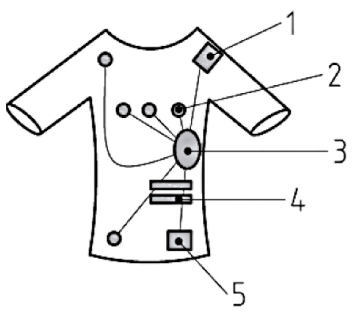
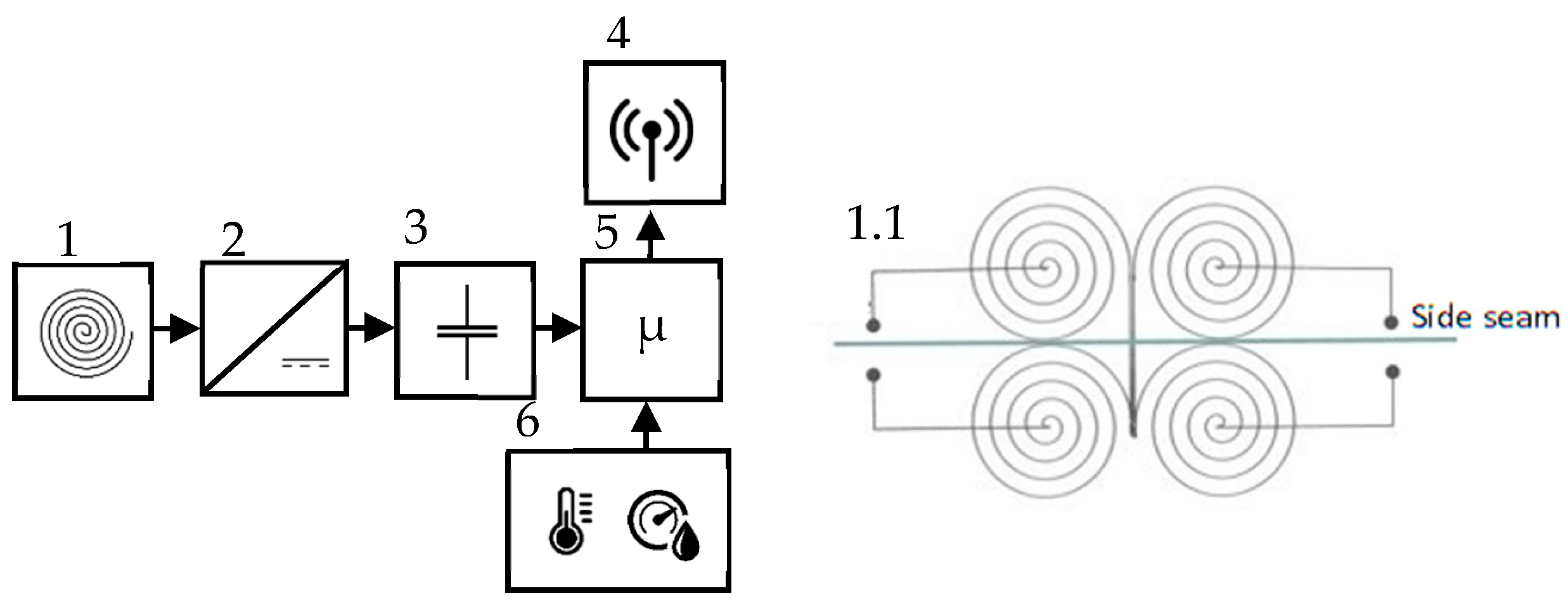
2.1. Development of an Electromagnetic Energy Converter

Within the framework of the research, an external energy source for a battery-independent human physiological and/or environmental parameter measurement and data transmission system was developed and integrated into clothing. The used source of energy was an electromagnetic human motion energy converter (EMC) integrated into the garment.
The system seen in Figure 3 consists of the following:
(1)
The transducer of human motion into electricity, operating on the principle of electromagnetic induction and consisting of four flat inductive elements connected in sequence and magnets moving along them (Figure 3, panel 1).
(1.1)
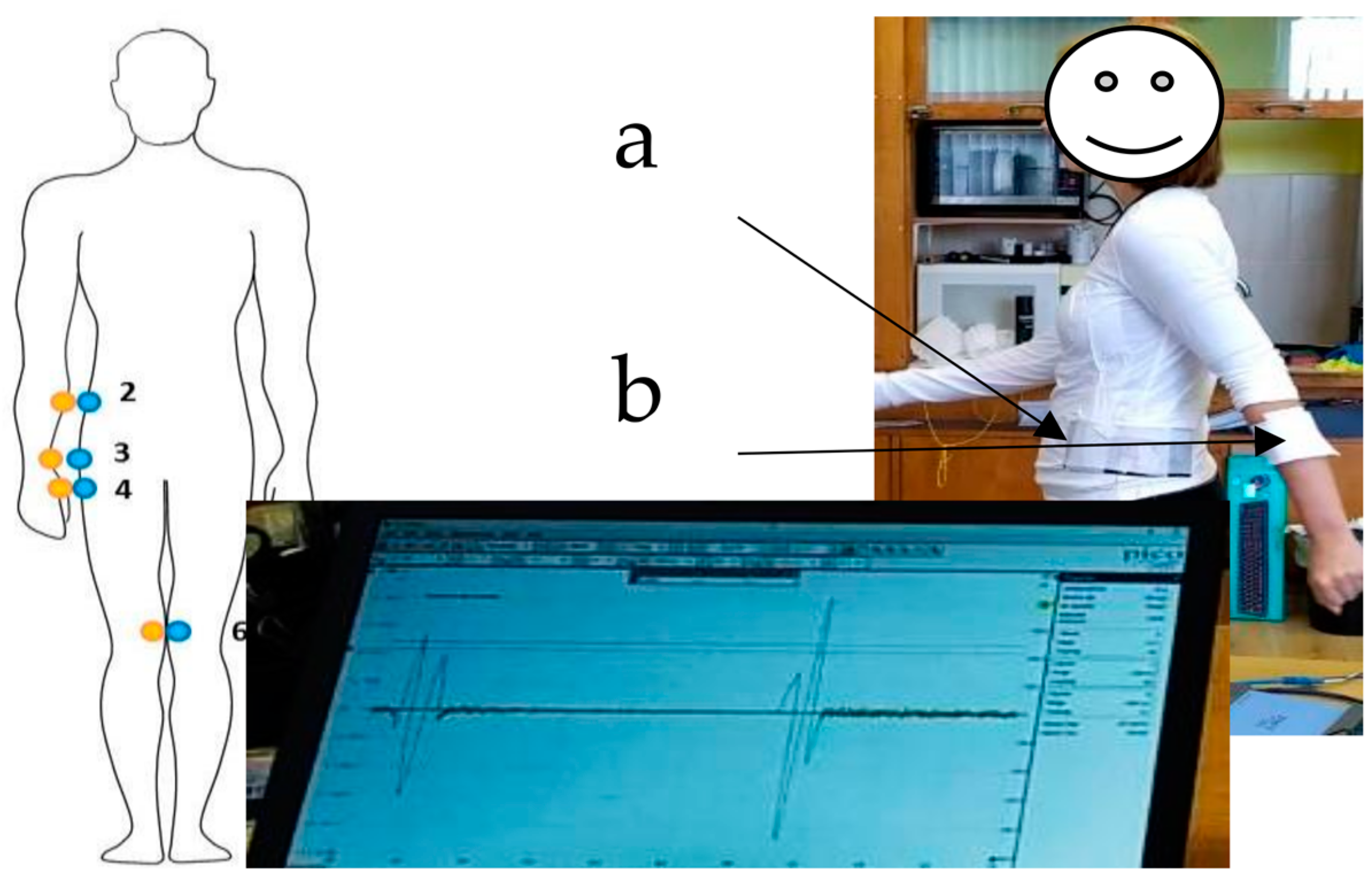
Each inductive element consists of five-layer coils in series (number of turns 50). The inductive elements are connected in such a way that the generated voltage pulses have opposite polarity, and the distance between the coil edges is 0 mm. The inductive elements are positioned so that the side seam of the long-sleeved shirt lies between the inductive elements (Figure 3, panel 1.1).
(2)
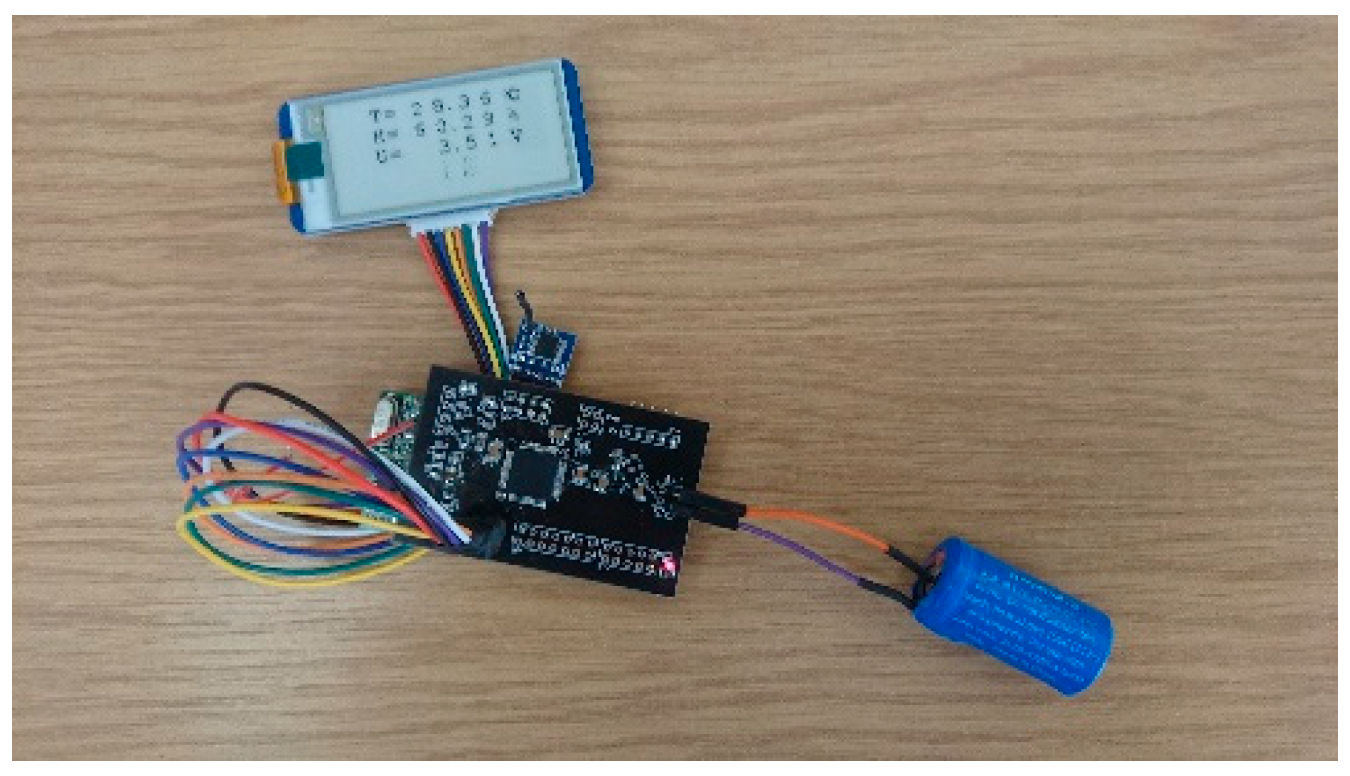
Module of the generated very low AC voltage conversion to the higher and more usable DC voltage (Figure 3, panel 2).
(3)
Module of energy storage, consisting of electrolytic capacitor, (Figure 3, panel 3).
(4)
Wireless data transmission module (Figure 3, panel 4).
(5)
Microcontroller unit to supervise work of data transmission and measurement modules (Figure 3, panel 5).
(6)
Module for measuring physiological and environmental parameters, consisting of temperature and relative humidity sensing units, placed on the inner surface of the shirt next to the induction elements and determining the corresponding parameters in the sub-cloth area (Figure 3, panel 6).
The manufactured coils were tested for electrical resistance compliance before and after one, five and ten washing and drying cycles. Motion capture technology provided by the Qualisys system (camera parameters: ProReflex MCU 240 Motion Capture) (Göteborg, Sweden) [12] was used for the speed of movement when walking. EMC electrical voltage measurement and data recording were carried out with a digital oscilloscope Tektronix TDS 2014 and Picoscope 2205 (Pico Technology), Cambridge UK) to observe the change of electrical voltage in a certain period of time.
The data processing of the experimental studies of the energy converter placed in the clothing, the generated energy and power calculations, and the statistical analysis and graphic visualization of the data were carried out using OriginPro 8.5 (Originlab, Northampton, MA, USA) and Excel computer programs (Microsoft, Redmond, WA, USA).

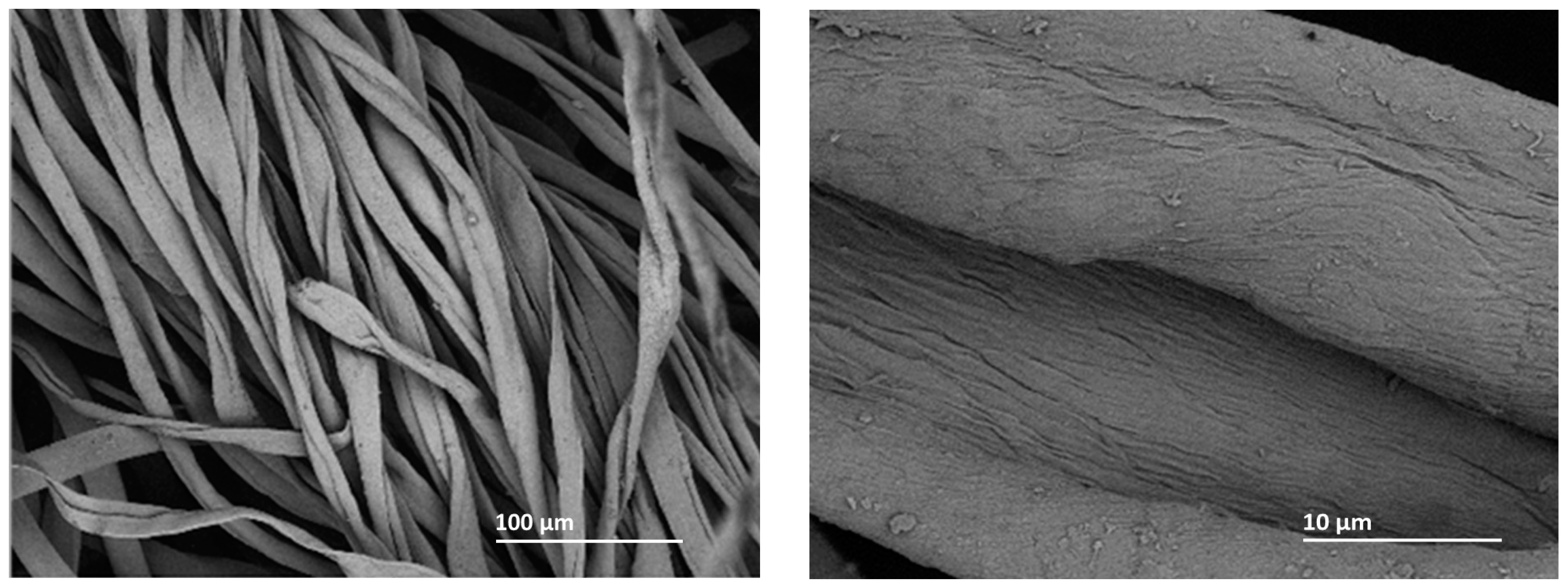
2.2. Nano-Scale Cotton Shirt Modification to Improve Wearer Comfort and Smart Shirt Sustainability

Sol–gel technique of film preparation is a comparatively low-cost process and is attractive as the coating properties can be tailored conveniently for a given application. In this paper, we present a discussion with the purpose of modifying a single jersey knitted cotton shirt (cotton 95%, elastane 5%). Nanosol coating with tetraethyl orthosilicate, TEOS (Acrōs Organics, Geel, Belgium) as the precursor was used since it allows the formation of coatings on such thermally unstable materials as textiles. Modification of cotton shirts has been conducted using a sol–gel reaction with TEOS. Ethanol (Sia Enola, Riga, Latvia) and water were added for the hydrolysis and condensation process, and hydrofluoric acid, HF (Sigma-Aldrich, Darmstadt, Germany) was used as a catalyst for the process. Zinc acetate dehydrate, ZAD 7.5 wt.% (Lach:ner, Neratovice, Czech Republic) was applied as a functional modifier [18].
For our studies, infrared-spectroscopy (ATR FT-IR) was adapted since analysis of the IR spectra has given important indications on the microstructural evolution with temperature and the influence of processing parameters. The spectra analysis is based on changes in absorption intensities and their differences between groups of samples because the complex composition of sample vibrational bands and peaks specific to the cotton cellulose overlap with the deposited nano-scale coating chemical compound’s vibrational bands and peaks. The spectra of the samples were taken with the Bruker Tensor II (Bruker, Billerica, MA, USA) spectrometer using the attenuated total reflection (ATR) method. Ten parallel measurements were performed in each set. Spectra processing was performed with the SpectraGryph Spectroscopy Software v1.2.16.1. (Dr. Friedrich Menges Software-Entwicklung, Oberstdorf, Germany) online program.
Micrograms of the surface of the samples were taken with a scanning electron microscope (SEM) with “SEM Mira Tescan H F”. The chemical composition analysis of the samples was performed using the “SEM Mira Tescan HF with Oxford Inca X-sight EDX” detector (Tescan, Brno, Chez Republic).
The air permeability was evaluated using the air permeability coefficient, measuring the amount of air that passes through a 5.07 cm2 sample area each time and at an air pressure difference on both sides of 50 and 100 Pa. The test was performed with the SDL Atlas Air Permeability device (SDL Atlas, Rock Hill, SC, USA) according to the standard (ISO 9237:1995) [20]. For each sample, 10 measurements were taken at different locations.
The wetting angle was determined with the optical tensiometer Theta Attention (Biolin Scientific, Gothenburg, Sweden) using the drop method with an accuracy of ±0.1°. The device automatically performs and records all measurements, recording droplet volume changes and wetting angle. For each sample, 3–5 measurements were made at one-minute intervals.
The Permetest Skin Model (Sensora, Liberec, Czech Republic) device determines relative water vapor permeability in the range of 0.5 to 100%. Before testing, the device is calibrated with standardized cloths (ISO 11092:2014) [21]. The temperature of the device and the air is set to 35 °C, and the relative humidity should be around 40%.
The processing of data obtained by following the appropriate standards of air permeability, wetting angle, and relative water vapor permeability was carried out by applying the appropriate methods of mathematical statistics using the EXCEL technological environment.

3. Results

3.1. Electromagnetic Energy Converter

Other studies have shown that the flat spiral shaped inductors can be used for converting human and apparel motion energy into electric energy [12]. An examination of the various coil placements has shown that preference has to be given to the set, where four induction coils are placed at the corners of a square and connected in a series circuit. Such an arrangement allows the use of all the coils in a useful space, and a series circuit ensures the mutually generated voltage impulse reinforcement. Effective operation of the electromagnetic energy converter (EMC) requires several conditions to be met [14]:
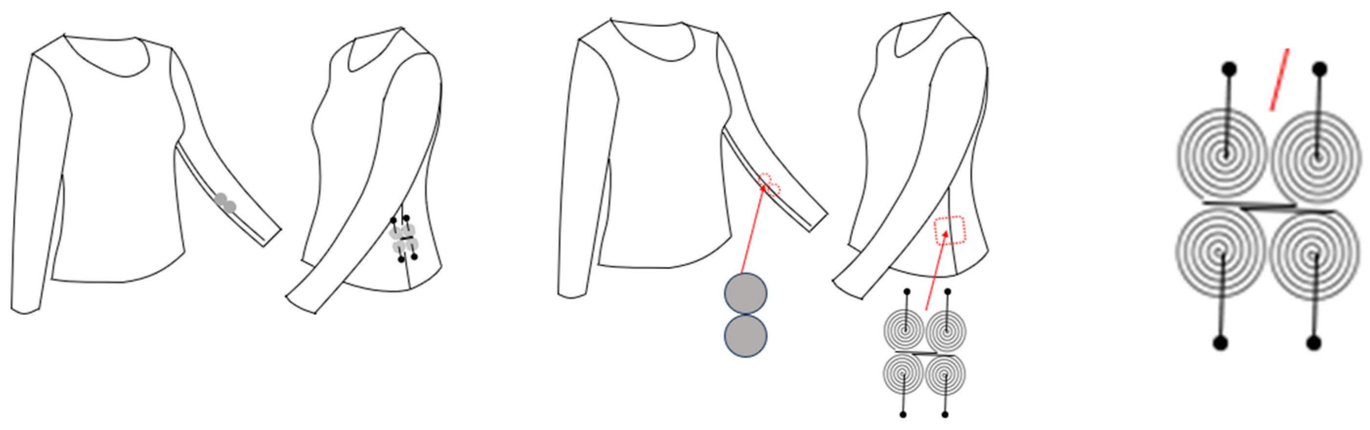
  • Parts of the converter must be positioned so that they move in relation to each other along with the corresponding parts of the clothing during its movement (Figure 4);
  • The surfaces with EMC parts should move along each other as closely as possible;
  • The location of the inductive elements should be as flat as possible and should not be subjected to deformation during movement;
  • The parts of the converter must not alter the characteristics of the garment and its appearance;
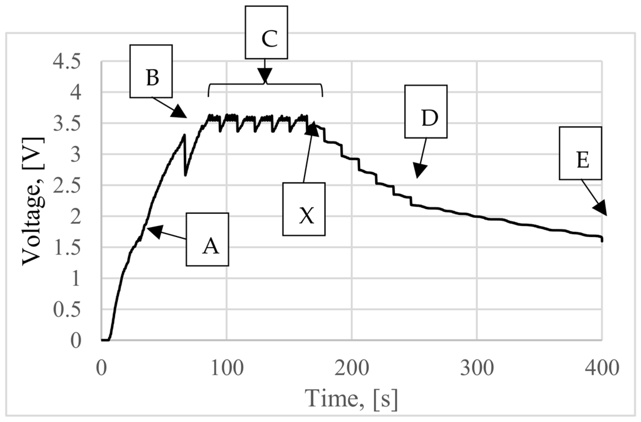
  • It is desirable to provide the maximum speed of magnet movement along inductive elements because the amount of energy generated is directly proportional to the energy of the magnet movement.
The most suitable EMC element placement is for a set to be about 8 cm under the waist (Figure 4 and Figure 5, left) of an upper or whole-body garment and the level of the wrist base [12]. The volume of the EMC is about 4.8 cm3, and the weight is 45 g.
The set of flat inductive elements integrated into the cotton shirt (Figure 4 and Figure 5, right, (a)) was placed at position 2, and the magnet set was placed on the wearers hand (Figure 5, right, (b)). Generated pulses of voltage were verified for various speeds (Figure 5, bottom). In the experiment, a test person was moving hands as during walking, making about 85 hand strokes per minute. The magnet moving along the stationary inductors created alternating magnetic flux, inducing a voltage in the inductors (Figure 4 and Figure 5).
The raw signal from flat inductor coils is further rectified, smoothed, and stored in the output capacitor that acts as a power source for measuring and data transmission blocks. Figure 5 illustrates the voltage on the output capacitor (1 mF, element 3 in Figure 3). It starts fully discharged, and after reaching 1.8 V, the microcontroller starts up and controls further processes. Figure 6 (bottom) shows how the voltage in the storage element changes during marching.
To minimize power loss and thus decrease charging time, the microcontroller does not initialize any module until a voltage level of above 3 V is achieved (Figure 7 (A)). Upon reaching a level with enough energy stored in a capacitor to safely initialize the data transmitter, the entire startup of the power control and energy accumulation system is complete (Figure 7, voltage drop at (B)), and the transmitter is put into sleep mode. The microcontroller maintains voltage monitoring and performs temperature and relative humidity measurements in regular intervals of 15 s, sending the data immediately to the remote station via 2.4 GHz frequency (Figure 7, voltage at (C)). These intervals were chosen for autonomous operation sustainability testing, showing that such an intensive operation is maintainable without additional power sources. In real-life operation, intervals could vary depending on specific tasks and energy stored in the capacitor; also, measurements can be stored for later batch transmission to save energy. When stored energy is too low and can result in unsuccessful measurement and transmission, the system stops operation to wait for more energy (Figure 7 (X to D)). Upon reaching a low voltage, the power is cut off (Figure 7 (E)).
The data are received on a remote host and displayed on an e-ink screen (Figure 8). The power source for the remote system is not limited to energy harvesters.
It was shown during the experiments that it took 175 s to charge the capacitor up to the first measurement at an average walking speed of about 3 km/h, accumulating about 4 mJ during this time. For energy usage, see Table 1.
By interrupting the movement and thus the resulting power flow to the output capacitor (at about 170 s, Figure 7), the system is still able to make a few measurements and only then stop working (voltage drops between points C and D, Figure 7).
The experimental evidence suggests that an electromagnetic human motion energy harvester with a flat structure can provide power for wireless data transfer and several sensor operations. By making the whole system modular, the overall volume and mass (20 cm3 and 150 g) do not use space as one block and can be distributed, allowing integration without significant effect on clothing. The obtained energy density is thus higher than other published motion energy harvesting solutions [12].

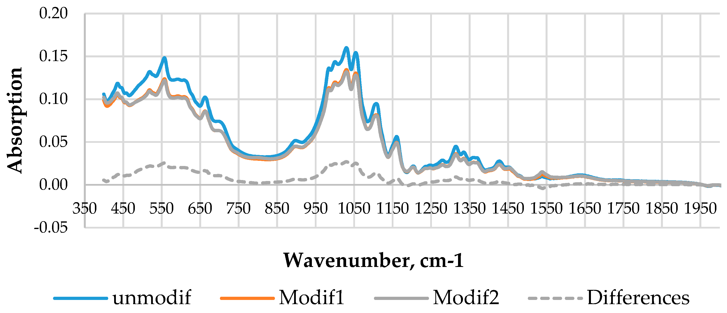
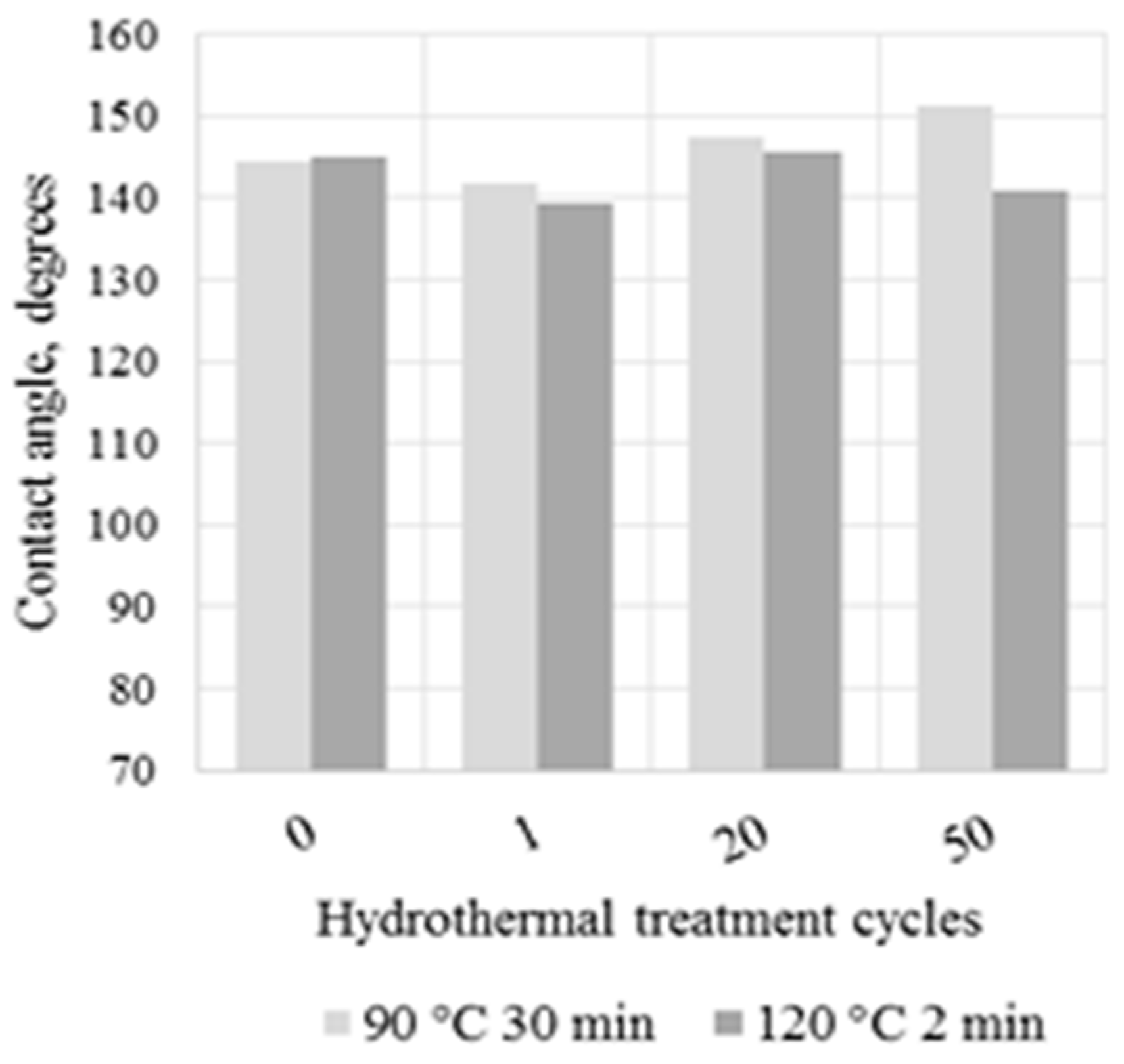
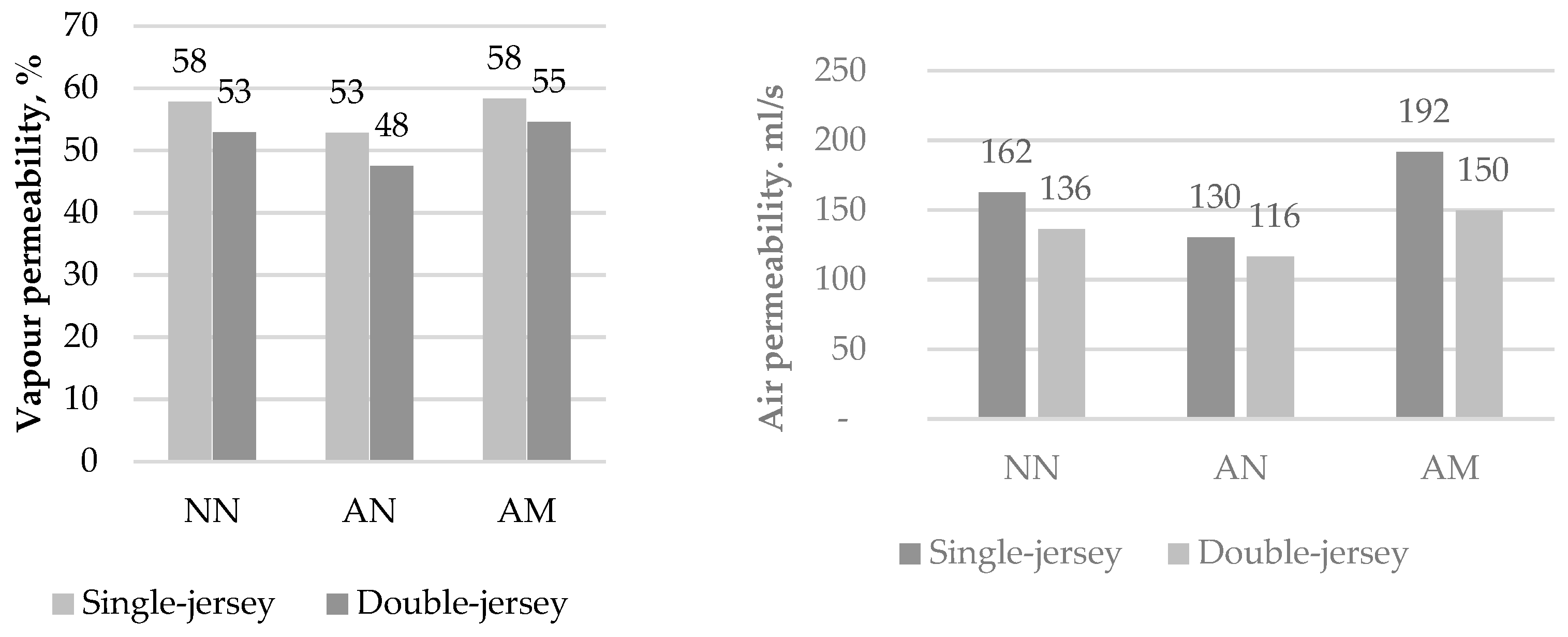
3.2. Nano-Scale Cotton Shirt Modification to Improve Wearer Comfort and Smart Shirt Sustainability

Nowadays, the sol–gel method is widely used due to its use of simple equipment and the possibility of using various precursors, and the method is relatively simple and allows processing of bulky products at a relatively low cost [22]. It has become an important method for obtaining nanoparticles and thin coatings based on inorganic or inorganic-organic materials [23], as it is possible to cover a wide range of diverse materials: glass, paper, wood, metals, polymers, and textiles [24].
Using this type of modification is expected to provide such additional functions as hydrophobicity, providing the self-cleaning effect that prolongs the product’s time between washing cycles, which is an important aspect to ensure the longevity of wearable electronic elements.
Nanosols were applied to the shirts using a pad-dry-cure process. As a result, a Zn acetate-incorporated silica network formed, and subsequent heat treatment results in a smooth, even hydrophobic film formation on fibers that is about 60 nanometers thick (Figure 9).
A comparison of the normalized spectra of unmodified and modified shirts (Figure 10 reveals that the spectra of the two sequentially modified shirts (Modif1 and Modif2) are virtually identical, demonstrating good repeatability of the modification process. In contrast, the spectra of differences allow estimation of the change in absorbance intensity of the coating in the frequency areas where characteristic peaks of cotton and sol compounds overlap.
The decrease in the absorption band of modified samples in the range of 3200 to 3400 cm−1 as well out-of-plane C-OH bond oscillations in the 660–670 cm−1 wavelength range indicate a reduced presence of intrinsic hydrogen bonds in comparison with the unmodified shirt. It means the amount of water present on the knit surface decreases.
Infrared radiation (IR) bands at 1090–1010 cm−1 and 955–830 cm−1 characterize the siloxane Si-O-Si and Si-OH groups, respectively, which are involved in the Si-O stretch. Alkoxy silanes, Si-O-R, are characterized by an out-of-phase stretch (1110–1000 cm−1) that results in a strong IR band and an in-phase stretch (1070–990 cm−1) [24,25,26,27]; thus, in the frequency range of 900–1300 cm−1, an almost complete overlap of the Si-alkoxy compounds with those specific for cotton is observed.
A crucial requirement for the use of sol–gel technology in textile-coating applications is a sufficient strength of bonding with the textile fibers to prevent the coating from peeling off during the hydrothermal treatment and use. Durability tests of modified cotton textile coatings with two condensation regimes (temperature respectively 90 and 120 °C; time 30 and 2 min) under multiple hydrothermal treatments indicate that a very good bonding strength was obtained between the coating and the cotton textile surface (Figure 11).
The movement of air, water vapor, and heat depend on the air space within the fabric and hence would obviously depend to some extent on the fabric structure guided by the total air space, and its distribution as it can be seen in graphs NN of Figure 12.
Vapor permeability tests of single- and double-jersey cotton long-sleeved shirts show an approximately 8–9% reduction in permeability after modification, but vapor permeability recovery is seen after the modified shirts are subjected to the hydrothermal treatment (Figure 12, left). A similar trend can be observed in graphs of Figure 12, right. Specifically, after modification, air permeability is decreased by 20% and 14% in single- and double-jersey cotton long-sleeved shirts, respectively, and increases by 18% and 10%, respectively, after hydrothermal treatment, during which the coating structure is completed.

4. Discussion

The voltage on the output capacitor is shown in Figure 5. This study demonstrates that the amount of the energy obtained from the human motion energy harvester and accumulated in a capacitor is enough to set up a system integrated into clothing for human physiological and/or environmental parameters detection and data transmission without dependence on an external power supply. The developed energy harvesting system for the conversion of mechanical energy of human movement into electrical energy is easily integrated both into clothing that comes into direct contact with the wearer’s skin and the outer layers of clothing, thus ensuring a wide range of applications without increasing the weight of the clothing significantly. By properly incorporating both elements of the converter into clothing, their long-lasting performance and the wearer’s comfort during body movement are ensured. This is especially important in smart clothing for work wear and special applications, sports, and recreation.
Nano-level coatings on cotton clothing surfaces retain the characteristic properties of cotton, including elasticity, lightweight, and breathability, and add multiple new features that are important to users, such as protection against ultraviolet radiation throughout its spectrum, antimicrobial activity, and resistance to wetting giving the effect of easy cleaning. This ensures the possibility of significantly reducing the washing intensity and intervals while increasing the overall performance of the entire smart clothing system. At the same time, the wearer’s thermophysiological and sensorial comfort is ensured. Various tests were conducted under the force of existing standards, displaying the new attribute of the efficiency of cotton textiles and durability of coatings even after multiple washer-drying cycles.

5. Conclusions

It is expedient to place elements of the developed system in clothing modified to provide comfortable outdoor use and simultaneous durability and physiological comfort for the wearer. Applying sol–gel technology (modified with 7.5 wt.% ZAD), it is possible to maintain such important properties for wearing comfort, such as water vapor and air permeability, and improve the hydrophobicity of the treated surface by maintaining the equilibrium angle of the surface above 100 degrees by applying a lower heating temperature and a longer time (90 °C and 30 min). These features also represent important characteristics for self-cleaning effects.
FTIR results indicate that the water amount decreased on the modified knitwear surface.
One of the challenges in modelling effective the operation of the electromagnetic energy converter (EMC) is the requirement that several conditions are met: the converter must be positioned perfectly, parts should move along each other as close as possible, and the maximum speed of magnet movement should occur along inductive elements. We can conclude that this electromagnetic human motion energy harvester with a flat structure can provide power for wireless data transfer and several sensor operations.
The research has succeeded in obtaining an energy harvesting system for converting the mechanical energy of human movements into electrical energy and integrating it into high-performance wearable clothing by combining an electromagnetic energy converter and nano-scale cotton shirt modification to improve wearer comfort and smart shirt sustainability.

Author Contributions

Conceptualization, S.K., J.B., G.T. and A.K.; methodology, S.K., J.B., A.K., V.J., I.G. and G.T; investigation, I.B., V.J., I.G., Z.Z. and A.O.; data curation, V.J. and I.G.; writing—original draft preparation, S.K., J.B., A.K. and I.B.; writing—review and editing, I.B. and Z.Z. All authors have read and agreed to the published version of the manuscript.

Funding

The article is published with the financial support from the RTU Research Support Fund. This work was supported by the ESF funded project “Synthesis of textile surface coating modified in nano-level and energetically independent measurement system integration in smart clothing with functions of medical monitoring” Nr.1.1.1.1. /16/A/020 (PVS ID 2588).

Institutional Review Board Statement

Not applicable, as the authors do not consider involving the Ethics Committee because the experiment involves casual clothing which does not affect the wearer.

Informed Consent Statement

Informed consent was obtained from all subjects involved in the study.

Data Availability Statement

The data presented in this study are available on request from the corresponding author.

Conflicts of Interest

The authors declare no conflict of interest.

References

  1. Singha, K.; Kumar, J.; Pandit, P. Recent Advancements in Wearable & Smart Textiles: An Overview. Mater. Today Proc. 2019, 16, 1518–1523. [Google Scholar]
  2. Okss, A.; Kataševs, A. Textile Transducer Device (TTD) for Strain and Pressure Measurements, System of TTD Used for Skin and Muscle Control and Stimulation, and Method of TTD Production from Conductive Piezoresistive Yarn Using Tuft or Terry Weaving or Knitting. Patent LV 14920 B, 2015. Available online: https://databases.lrpv.gov.lv/patents/P-14-58 (accessed on 15 October 2023).
  3. CEN/TR 16298:2011; Textiles and Textile Products—Smart Textiles—Defnitions, Categorization, Application and Standardization Needs. iTeh, Inc.: Newark, DE, USA, 2011.
  4. Stygiene, L.; Varnaite-Zuravliova, S.; Abraitienė, A.; Padleckiene, I.; Krauledas, S. Investigation of Textile Heating Element in Simulated Wearing Conditions. Autex Res. J. 2020, 21, 207–215. [Google Scholar] [CrossRef]
  5. Hou, Z.; Liu, X.; Tian, M.; Zhang, X.; Qu, L.; Fan, T.; Miao, J. Smart fibers and textiles for emerging clothe-based wearable electronics: Materials, fabrications, and applications. J. Mater. Chem. A 2023, 11, 17336–17372. [Google Scholar] [CrossRef]
  6. Jeong, K.S.; Yoo, S.K. Electro-Textile Interfaces: Textile-Based Sensors and Actuators. In Smart Clothing—Technology and Applications—Human Factors and Ergonomics; Cho, G., Ed.; CRC Press: Boca Raton, FL, USA, 2010; pp. 89–114. [Google Scholar]
  7. McKnight, M.; Agcayazi, T.; Ghosh, T.; Bozkurt, A. Chapter 8—Fiber-Based Sensors: Enabling Next-Generation Ubiquitous Textile Systems. In Wearable Technology in Medicine and Health Care; Raymond, K.-Y.T., Ed.; Academic Press: Cambridge, MA, USA, 2018; pp. 153–171. ISBN 9780128118108. [Google Scholar]
  8. Vagott, J.; Parachuru, R. An Overview of Recent Developments in the Field of Wearable Smart Textiles. J. Textile Sci. Eng. 2018, 8, 4. [Google Scholar] [CrossRef]
  9. Kang, D.; Rongzhou, L.; Lu, Y.; John, S.; Ho, J.W.; Chwee, T.L. Electronic textiles for energy, sensing, and communication. iScience 2022, 25, 104174, ISSN 2589-004. [Google Scholar]
  10. Jatoi, A.S.; Khan, F.S.A.; Mazari, S.A.; Mubarak, N.M.; Abro, R.; Ahmed, J.; Ahmed, M.; Baloch, H.; Sabzoi, N. Current applications of smart nanotextiles and future trends. In Nanosensors and Nanodevices for Smart Multifunctional Textiles; Elsevier: Amsterdam, The Netherlands, 2021; Chapter 19, pp. 343–365. [Google Scholar]
  11. Nagamine, K.; Sekine, T.; Tokito, S. Printed Electronics-Enabled Wearable/Portable Physical and Chemical Sensors for Personal Digital Healthcare. In Encyclopedia of Sensors and Biosensors, 1st ed.; Narayan, R., Ed.; Elsevier: Amsterdam, The Netherlands, 2023; pp. 68–79. ISBN 9780128225493. [Google Scholar]
  12. Terļecka, G. Integration of Human Motion Energy Converter into Clothing. Ph.D. Thesis, Riga Technical University, Riga, Latvia, 2019. [Google Scholar]
  13. Grabham, N.J.; Li, Y.; Clare, L.R.; Stark, B.H.; Beeby, S.P. Fabrication Techniques for Manufacturing Flexible Coils on Textiles for Inductive Power Transfer. IEEE Sens. J. 2018, 18, 2599–2606. [Google Scholar] [CrossRef]
  14. Gurova, O.; Merritt, T.; Papachristos, L.; Vajakaari, J. Sustainable Solutions for Wearable Technologies: Mapping the Product Development Lifecycle. Sustainability 2020, 12, 8444. [Google Scholar] [CrossRef]
  15. McCann, J. Identification of design requirements for smart clothes and wearable technology. In Smart Clothes and Wearable Technology, 2nd ed.; The Textile Institute Book Series; Woodhead Publishing: Sawston, UK, 2023; pp. 327–369. [Google Scholar]
  16. Morais, D.S.; Guedes, R.M.; Lopes, M.A. Review: Antimicrobial Approaches for Textiles: From Research to Market. Materials 2016, 9, 498. [Google Scholar] [CrossRef] [PubMed]
  17. Moellebjerg, A.; Palmén, L.; Gori, K.; Meyer, R. The Bacterial Life Cycle in Textiles is Governed by Fiber Hydrophobicity. Microbiol. Spectr. 2021, 9, e0118521. [Google Scholar] [CrossRef] [PubMed]
  18. Vihodceva, S.; Kukle, S.; Bitenieks, J. Durable Hydrophobic Sol-Gel Finishing for Textiles. IOP Conf. Ser. Mater. Sci. Eng. 2015, 77, 012023. [Google Scholar] [CrossRef]
  19. Schubert, U. Chemistry and Fundamentals of the Sol–Gel Process. In The Sol–Gel Handbook: Synthesis, Characterization, and Applications, Levy D., Zayat, M., Eds., 1st ed.; Wiley-VCH Verlag GmbH & Co. KgaA: Weinheim, Germany, 2015. [Google Scholar]
  20. ISO 9237:1995; Textiles—Determination of the Permeability of Fabrics to Air. ISO: Geneva, Switzerland, 1995. Available online: https://www.iso.org/standard/16869.html (accessed on 15 October 2023).
  21. ISO 11092:2014; Textiles—Physiological Effects—Measurement of Thermal and Water-Vapour Resistance under Steady-State Conditions (Sweating Guarded-Hotplate Test). ISO: Geneva, Switzerland, 2014. Available online: https://www.iso.org/standard/65962.html (accessed on 15 October 2023).
  22. Shah, M.A.; Pirzada, B.M.; Price, G.; Shibiru, A.L.; Qurashi, A. Applications of nanotechnology in smart textile industry: A critical review. J. Adv. Res. 2022, 38, 55–75. [Google Scholar] [CrossRef] [PubMed]
  23. Periyasamy, A.P.; Venkataraman, M.; Kremenakova, D.; Militky, J.; Zhou, Y. Progress in Sol-Gel Technology for the Coatings of Fabrics. Materials 2020, 13, 1838. [Google Scholar] [CrossRef] [PubMed]
  24. Baķe, I.; Kukle, S.; Beļakova, D. Surface Characteristics of Sol-Gel Treated Single Jersey Plated Socks. J. Eng. Fibers Fabr. 2021, 16, 1–9. [Google Scholar] [CrossRef]
  25. Larkin, P. Infrared and Raman Spectroscopy Principles and Spectral Interpretation; Elsevier: Amsterdam, The Netherlands, 2017; ISBN 978-0-12-386984-5. [Google Scholar]
  26. Yang, G.; Song, J.; Hou, X. Fabrication of highly hydrophobic two-component thermosetting polyurethane surfaces with silica nanoparticles. Appl. Surf. Sci. 2018, 439, 772–779. [Google Scholar] [CrossRef]
  27. Saputra, R.E.; Astuti, Y.; Darmawan, A. Hydrophobicity of silica thin films: The deconvolution and interpretation by Fourier-transform infrared spectroscopy. Spectrochim. Acta Part A Mol. Biomol. Spectrosc. 2018, 199, 12–20. [Google Scholar] [CrossRef]
Figure 1. Smart clothing system. (1) Communication links components of the clothing, transferring information and energy; (2) sensors provide information from wearer, devices, or the environment; (3) microprocessor refers to memory and data processing; and (4) energy source; (5) actuator—energy management relates to energy supply and storage [3,4].
Processes 11 03056 g001
Figure 2. Human aspects in smart clothing [14].
Processes 11 03056 g002
Figure 3. Electronic system structure scheme.
Processes 11 03056 g003
Figure 4. Placement of four flat inductive elements connected in sequence and magnets embedded in the sleeve of the shirt and moving relative to inductive elements when the wearer marches.
Processes 11 03056 g004
Figure 5. Selected locations of the electromagnetic energy converter components and testing. (a) Placement of flat inductors; (b) placement of permanent magnets. (2) Chosen position of energy converter and it components and (3, 4, 6) other possible positions.
Processes 11 03056 g005
Figure 6. Voltage pulses induced during motion of wearers hand. Generated pulses of voltage (top); two voltage pulses generated over two consecutive steps (bottom).
Processes 11 03056 g006
Figure 7. Voltage on output capacitor during the energy accumulation, configuration of the system, sensor powering, and data transmission.
Processes 11 03056 g007
Figure 8. Remote data receiver with one data packet on the screen; received information contains temperature, relative humidity, and output capacitor voltage measurements.
Processes 11 03056 g008
Figure 9. Micrographs of coated cotton fibers from the knitted shirts. SEM mag.: (left) 5.00×, (right) 500×.
Processes 11 03056 g009
Figure 10. FTIR absorption spectra of unmodified and modified single-jersey cotton shirts.
Processes 11 03056 g010
Figure 11. Contact angle changes (surface wettability) depending on the number of hydrothermal treatment cycles.
Processes 11 03056 g011
Figure 12. Vapor permeability (left) and air permeability (right). NN unmodified; AN modified; AM modified, washed.
Processes 11 03056 g012
Table 1. Energy usage.
Nr.ActionEnergy Usage
1Microcontroller initialization0.3 mJ
2Transmitter initialization2.8 mJ
3Measurement and data transmission0.4 mJ
Disclaimer/Publisher’s Note: The statements, opinions and data contained in all publications are solely those of the individual author(s) and contributor(s) and not of MDPI and/or the editor(s). MDPI and/or the editor(s) disclaim responsibility for any injury to people or property resulting from any ideas, methods, instructions or products referred to in the content.

