Article

An Automatic Welding Robot for the Roof of Spiral Steel Silo

1
School of Mechanical Engineering, Jiangsu University, Zhenjiang 212013, China
2
Jiangsu Hengxin Silo Equipment Co., Ltd., Changzhou 213000, China
*
Author to whom correspondence should be addressed.
Processes 2023, 11(11), 3049; https://doi.org/10.3390/pr11113049
Submission received: 13 September 2023 / Revised: 30 September 2023 / Accepted: 18 October 2023 / Published: 24 October 2023

Abstract

:
A spiral steel silo has become the preferred choice for building steel silos because of its short construction period, low cost, and high strength. Owing to the harsh outdoor welding conditions of the spiral steel silo and the high risk of manual welding, in this paper, an automatic welding robot is proposed, and its key technology is studied. The welding process parameters consisted of welding voltage, current, and the distance between the conductive nozzle and the base material, which were determined through experiments. The key technology of seam tracking on the roof of a spiral steel silo was studied. Finally, a weld bead tracking experiment and prototype welding experiment were carried out. The results suggest that the prototype can track the weld bead stably and accurately, and the welding effect can meet welding process requirements when the welding current is 200 A, the voltage is 20 V, and the distance between the welding nozzle and the base material is 12 mm.

1. Introduction

A steel silo is a type of storage equipment that is used to store cement, grains, fly ash, clinker, aggregate, coke, pellets, and other powdery granular materials [1,2,3]. The dimensions of a spiral steel silo are usually large. The length of the weld bead on the roof of a steel silo tends to be more than 30 m [4,5]. The number of weld beads on the roof of the steel silo reaches more than 60 and a total length of nearly 600 m. The roof of the spiral steel silo has a certain slope, usually 25 degrees, and the welding condition is extremely harsh [6]. Traditional manual welding can no longer meet the welding needs of spiral steel plate silos, and ordinary welding robots on the market cannot weld such large workpieces as well. Hundreds of hours and tens of thousands of yuan need to be spent on welding spiral steel silos.
Therefore, it is necessary to develop a welding robot that is dedicated to special welding conditions on the roof of spiral steel silo. The use of mobile welding robots to replace manual work can not only significantly reduce labor costs but also improve welding efficiency and ensure the quality of welding, which has become a critical development direction in the field of engineering and welding.
At present, different degrees of exploration and research have been carried out on welding automation at home and abroad [7,8,9,10]. The DANDY welding system developed by Lee JH has been used for hull welding at the Daewoo Shipyard in South Korea [11]. The advanced automatic welding system for offshore pipeline systems with a seam-tracking function developed by Jin Hyeong Park in South Korea greatly improved the efficiency of pipeline welding [12]. Hascoet J Y and other scholars of the French National Academy of Sciences developed a new robot welding system in combination with SHIPWELD [13]. The system also had a camera that allowed the operator to monitor the welding process in real-time. A novel on-site all-position welding robot system for the steel box girder studied by Guo Jichang and others from China realized the all-position automatic welding of the girth butt weld of the box girder in a spatial position [14]. Scholars, such as Li Aimin from China University of Mining and Technology, have developed an automatic welding robot based on PLC [15]. This PLC-controlled automatic welding robot can improve welding quality and efficiency, reduce labor intensity, and bring huge economic benefits. The Portuguese GECAD Scientific Engineering and Decision Center developed a wheel-type wall-climbing robot with controlled magnetic adsorption [16]. The robot driving system regulated the adsorption by varying the distance between the permanent magnet and the wall of structural steel by changing the screw. Research on the electromagnetic and negative pressure coupling adsorption technology of wall–climbing robots, which was developed by Ying Xu from China, is of great significance in improving the level of safety monitoring during the construction and service of coal mine shafts [17]. Lu Hong from China proposed an intelligent welding path generation algorithm based on the multi-section interpolation for non-standard multi-pass welding grooves, which are difficult to handle by automatic welding equipment on the construction site [18]. In order to solve the problem of poor mechanical properties in filling materials compared with substrates that have excellent mechanical properties, Jaewoong Kim from South Korea performed the application of fiber laser welding with low welding deformation and no filler material to high-manganese steel [19]. However, there is relatively little research on welding technology for the long-straight welding of the outdoor slope, especially the automatic welding of the steel silo roof.
In this study, based on existing automatic welding technology [20], automatic welding technology for the roof of a spiral steel silo was studied and developed according to the welding process and special working conditions of the roof of a spiral steel silo [5,21]. The main studies are as follows:
  • The structural design of the prototype was carried out for the weld bead characteristics of the spiral steel silo and special welding conditions at the roof of the silo.
  • In this paper, material properties and the weldability of the roof for a spiral steel silo were analyzed, the welding process experiment of a spiral steel silo was carried out, and appropriate welding process parameters were selected.
  • Critical technologies for monitoring the weld bead on the roof of a spiral steel silo were investigated, and the structural light detection principle of the laser weld bead sensor was analyzed. The principles of related algorithms consisting of weld bead image enhancement, image filtering, binarization processing, and Harris corner detection processing based on Halcon were studied, and least squares polynomials were used to fit the weld bead trajectory.
  • Finally, weld-tracking experiments and prototype-welding experiments were carried out, and the experimental results were analyzed. The results suggest that the prototype has a certain stability and accuracy in tracking the weld bead.

2. Materials and Methods

2.1. Weld Bead Characteristics and Welding Process at the Roof of Spiral Steel Silo

2.1.1. Characteristics of Roof of Steel Silo

The spiral steel silo roof mainly consists of channel steel and the steel silo roof plate. As shown in Figure 1, the models of channel steel are generally No. 5, 6.3, and 8. The plurality of channel steel as a structural part includes an umbrella-shaped distribution, where the slope is generally 25°, as the skeleton of the whole silo roof, which supports the upper silo roof. As shown in Figure 2, the steel silo roof plate is made of double-sided high-quality hot-dip galvanized steel plate with a thickness of 2.5 mm, a coating density of 275 g/m2, and the base material of the steel plate is Q235B.
Because the spiral steel silo needs to store a large amount of material for a long time, the strength and stiffness of the material is very important. It needs to be able to withstand the loads and external forces of the steel silo in the process of use. And water vapor in the atmosphere and the materials stored in the steel silo exert some corrosion on the steel. Q235B is a common low-carbon steel that not only has good strength and stiffness but also has good corrosion resistance. In addition, the price of Q235B is relatively low, which can save costs.

2.1.2. Determination of Welding Process

The welding test in this project adopts gas metal arc welding with CO2. The main parameters of the steel silo roof plate welding process experiment consist of the welding current, welding voltage, gas flow, welding speed, and distance between the conductive nozzle and the base metal. The thickness of the workpiece is 2.5 mm. According to the relevant literature [22], a 1.2 mm diameter Flux-Cored wire commonly used on the market was selected for the test. The gas flow value of welding shielding gas is usually 10 times the diameter of Flux-Cored wire and the welding speed is 40 cm/min.
The three parameters mentioned above were fixed. The width and height data of the welding path under different welding currents, voltage, and the distance between the conductive nozzle, and the base metal were measured, and mathematical analyses were carried out to select the appropriate process parameters.
A large number of steel plates with overlap welds of 120 mm in length were prepared for the following tests:
  • Welding current and voltage test
    • Experimental process
    The welding current and voltage test which includes 12 groups of welding tests, as shown in Table 1.
    ii.
    Analysis of experimental results
    After the completion of the welding test, an average of 12 points were selected for each weld path, and the height and width of each spot weld path were measured, respectively. The point-line diagrams were drawn according to data of the measurement points, and the comparisons of experimental data are shown in Figure 3.
2.
Distance test between conductive nozzle and base metal
i.
The experimental process
Based on the previous experimental results, four sets of experiments were carried out by adjusting the welding current and voltage to optimum values, and the data obtained are shown in Table 2.
ii.
Analysis of experimental results
Consistent with the analysis method of the current and voltage experimental results mentioned above, measurement points were selected, and point line diagrams were drawn. The curve of the height and width of the weld pass is shown in Figure 4.
It is concluded that the error of curve 8 in Figure 3 is the smallest through the error calculation and analysis, in which the mean squared error of curve 8 in Figure 3a,b is 0.31 mm and 0.29 mm, respectively, and the mean absolute errors are all 0.23 mm. The error of curve 2 in Figure 4 is the smallest, in which the mean squared error of Figure 4a,b is 0.23 mm and 0.27 mm, respectively, and the mean absolute is 0.19 mm and 0.23 mm, respectively.
Finally, the optimal welding process parameters for the silo roof plate were as follows: current at 200 A, voltage at 20 V, and distance between the conductive nozzle and the base metal was 12 mm.

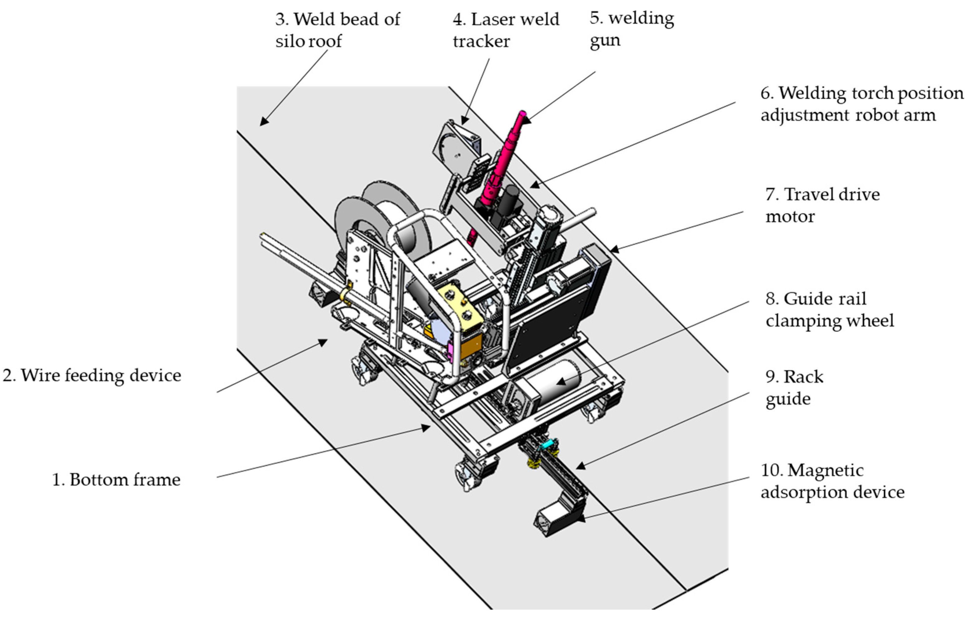
2.2. Mechanical Structure

The overall mechanical structure of automatic welding on the roof of the spiral steel silo plate is shown in Figure 5. The equipment mainly included the following parts: the aluminum alloy bottom frame ensured that the whole frame met the strength requirements and greatly reduced the weight of the equipment, which is convenient for handling and the warehouse roof operation. For the wire feeding device, because the weld bead of the silo roof was long, this device could move with the whole equipment and reduce the wire transmission cable between the welding gun and the welding current and voltage, facilitating real-time regulation. The rack guide rail ensured the stability and safety of the equipment during welding through the traveling mode of the guide rail. A magnetic adsorption device was used for the installation and fixation of the guide rail on the silo roof. It can manually adjust the on-off of the magnetic circuit to ensure that the magnetic adsorption force meets the technical requirements and is easy to install and disassemble [23,24,25,26]. The guide rail clamping wheel is used to clamp the guide rail, prevent the equipment from derailing, and improve the safety and stability of the equipment. The welding gun position adjusting robot arm can adjust the position, clamping posture, and welding angle of the welding gun in multiple positions, which sufficiently meets the adaptability of the equipment to the welding position of the silo roof and greatly improves welding quality. The laser weld tracker uses the direct laser triangulation method to detect, which can quickly identify and extract weld bead feature point information, complete the trajectory fitting, and feedback to the main controller to complete the welding.

2.3. Key Technologies of Welding Seam Tracking at the Roof of Spiral Steel Silo

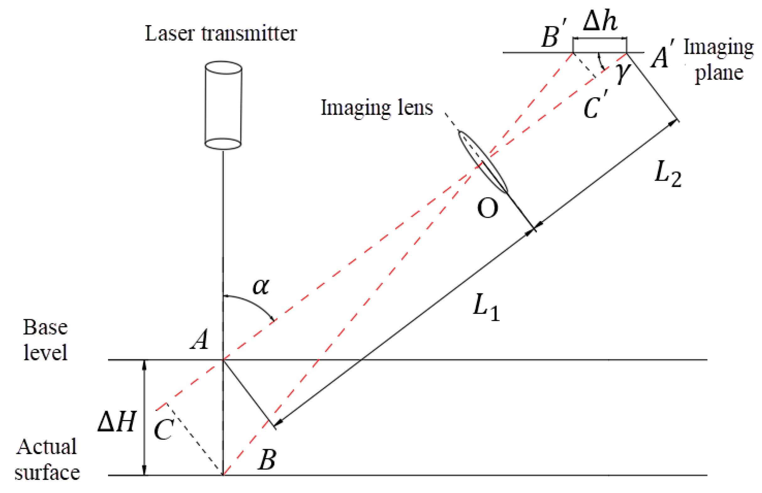
2.3.1. Principle of Structured Light Detection

The weld bead tracking system is composed of the weld bead tracking sensor and related image processing software. The main function of the weld bead tracking sensor is to quickly identify and locate the position of the weld bead feature point, the shape of the groove and the weld bead trajectory [27].
The active optical weld bead tracking sensor was generally composed of a laser generator, camera, filter, corresponding signal processor, and so on. Weld bead information was obtained using the optical imaging principle and visual processing technology. The laser was used as an auxiliary light source to project the surface of the workpiece, and laser stripes were formed on the surface of the workpiece. The textured shape of the light band was captured by the camera. After image acquisition, the weld bead shape and position information were processed to realize the automatic tracking of the weld bead. The weld bead on the roof of the spiral steel silo needed to be tested and tracked outdoors. The structure of the testing equipment was simple and convenient, and the volume was small. The silo roof plate as hot-dip galvanized material produced large spatter and smoke during welding. The scattering property of the detection equipment and the corresponding relationship between the spot, and the position was good; the laser was concentrated, and the spot was small. In this paper, direct laser seam tracking was used for seam identification and tracking.
The principle of direct laser triangulation is shown in Figure 6. The laser emitter emits a laser beam to the actual plane. According to Scheimpfulg’s law, the laser beam reflects on the measured surface, and part of the diffuse reflected light appears on the imaging surface through the imaging lens. The laser beam intersects with the datum plane at point A. This light is projected onto the imaging surface to form point A′ on the imaging plane, and α is the working angle. The actual plane is moved to point B with a moving distance of Δ H . This light is projected onto the imaging surface to form point B′ on the imaging plane, and the distance between point A′ and point B′ on the imaging plane is Δ h . Points C and C′ are the pedal points of B and B′ are on line AA′. The object distance is L 1 and the image distance is L 2 , according to the following mathematical knowledge: Δ A B C Δ A B C , Δ O B C Δ O B C .
From the similar properties of triangles, the following expression can be obtained:
B C B C = O C O C
In the equation above,
B C = Δ H sin α , B C = Δ h sin γ , O C = L 1 + Δ H cos α , O C = L 2 Δ h cos γ
Δ H sin α Δ h sin γ = L 1 + Δ H cos α L 2 Δ h cos γ
According to Equation (3), the actual surface displacement distance is as follows:
Δ H = L 1 Δ h sin γ L 2 sin α Δ h sin ( α + γ )
The displacement distance on the imaging surface is as follows:
Δ h = L 2 Δ H sin α L 1 sin γ + Δ H sin ( α + γ )
Similarly, when the actual surface moves toward the laser emitter relative to the reference surface, the displacement distance formula between the actual surface and the imaging surface is as follows:
Δ H = L 1 Δ h sin γ L 2 sin α + Δ h sin ( α + γ )
Δ h = L 2 Δ H sin α L 1 sin γ Δ H sin ( α + γ )
It can be seen from the above equation that the actual moving distance Δ H of the object can only be found by finding the moving distance Δ h of the point on the imaging surface [28].

2.3.2. Image Processing

Image processing for the weld tracking system includes image acquisition, image preprocessing, weld seam feature extraction, weld seam fitting, etc. The image acquisition of Halcon can be divided into real-time image acquisition and delayed image acquisition. According to the needs of the project, real-time image acquisition is selected. The original weld bead image acquired is shown in Figure 7.
There are various kinds of noise in the original image captured by the camera. Image enhancement can highlight the details of the image and eliminate useless noise information.
  • Image graying
In the process of image processing, to reduce the redundant workload and extract useful weld seam information faster, it is necessary to extract the ROI area of the image and convert it into a gray-scale image. This operation can only focus on the laser irradiation area, which is conducive to the extraction of weld seam feature points in the later stage. As shown in Figure 8, it is a gray-scale image of the ROI (region of interest) area divided by the original image.
2.
Median filtering
The principle of median filtering is to take the middle value of the sequence of gray value sizes within the neighborhood of the pixel center.
Value filtering can effectively remove isolated noise points while retaining most edge information in image smoothing. However, if the filter size is too large, the image can become blurred. The median filtering effect is shown in Figure 9.
3.
Image binarization
After image smoothing and denoising are completed, image binarization is needed to separate the laser fringe from the whole background, which is convenient for welding seam feature point extraction in the next step.
In this paper, the image acquisition is disturbed by various noises in the field conditions, and the image processing needs to be flexible. Therefore, the adaptive threshold method was selected in this paper to carry out image threshold segmentation, and the processing effect is shown in Figure 10. The current threshold value is 157.
4.
Feature point detection
The feature point of the weld bead is the point that can express the information of the weld bead’s position. For the corner point, the mathematics field has not yet been clearly defined, and it can generally be considered as the point with special prominent attributes. In the welding image in this paper, the intersection of the laser line and weld bead is the required corner point, and Harris corner detection identifies and extracts the feature point of the weld. Harris corner detection generally uses the local window to calculate the image gray value, where the local window is moving, and the calculated gray value also changes.
As shown in Figure 11, Harris is used for corner detection. The red cross point in the figure is the corner point, which can adequately find the position of the weld bead.
5.
Trajectory fitting
After the recognition and extraction of weld bead feature points, a series of weld bead position points appear. At the same time, the information of these position points is in a discrete state. It is necessary to conduct trajectory fitting to obtain a weld bead trajectory, which is transmitted to the control system to command the welding gun to track welding. In this paper, the least square method principle was used for polynomial fitting [29]. The trajectory fitting is shown in Figure 12.

3. Results

3.1. Weld Tracking Test

A number of experimental steel plates with an overlap weld bead length of 300 mm were prepared, and the position of the cross-module was adjusted for the experiment. The spatial coordinate system was established with the roof plate plane as the reference plane: the left–right direction of the welding gun’s movement was set as the X-axis, the walking direction of the welding robot was set as the Y-axis, and the up–down direction of the welding gun’s movement was set as the Z-axis. The moving speed of the prototype was set to 400 mm/min. The X-axis and Z-axis movement information from the upper computer was recorded every 3 s, and the actual position of the weld bead point was measured simultaneously. Ten sets of data were recorded. The weld tracking experiment is shown in Figure 13.
According to the test process, the prototype moved on the rack guide rail, and the guide rail was parallel to the Y-axis. The Y-axis coordinate of the welding trajectory was equal to the actual Y-axis coordinate theoretically, and the position information of the weld points for ten experiments is shown in Table 3. A schematic diagram is shown for the weld point location information in Table 3, where L1 is the actual measured weld bead point trajectory and L2 is the weld point trajectory fed back by the upper computer, as shown in Figure 14.
It can be seen from Table 3 that the mean absolute error of the X-axis measurement was 0.38 mm, and the maximum absolute error was 0.63 mm, while the mean absolute error of the Z-axis measurement was 0.67 mm, and the maximum absolute error was 1.18 mm. Combined with Figure 14, it can be seen that the prototype in this test had good accuracy and stability in terms of weld tracking.

3.2. Welding Test

The prototype welding robot test was conducted on a small test platform with a slope of 25 degrees, simulating the actual working conditions of a spiral steel plate silo, as shown in Figure 15. The position of the prototype was adjusted, and the selected welding process parameters were set before conducting ten sets of experiments, with each welding length reaching 1500 mm.
The effect diagram of the welding experiment is shown in Figure 16. Twenty-one points were selected on average along the weld path, and the width and height of the weld bead were measured. The scatter plot, as shown in Figure 17, was created to illustrate variations in height and width.
The error was calculated according to the measured data. In ten welding tests, the maximum mean squared error and mean absolute error for the height change in the welding channel were 0.22 mm and 0.19 mm, respectively, and the maximum mean squared error and mean absolute error of the width change in the welding channel were 0.30 mm and 0.26 mm, respectively.
It can be found that the mean absolute error and the mean square error of the height and width of the welded bead were within a reasonable range, and the height and width of the welded bead did not show any significant abnormal changes, proving that the welding process was relatively smooth and the effect of welding was good.

4. Discussion

The novelty of this paper is the development of a specialized welding robot that can climb slopes for the special working conditions of the spiral steel silo roof. This type of welding robot is currently rare in the domestic and international markets. It adopts the magnetic adsorption method to lay the track, which is easy to install and dismantle. In the process of climbing, the crawling is stable. From the final data, the mean absolute error in the horizontal positioning of the welding gun was 0.38 mm, and the maximum absolute error was 0.63 mm. The mean absolute error of the vertical positioning of the welding gun was 0.67 mm, and the maximum error was 1.18 mm, from which it can be seen that the weld bead tracking effect is suitable.
However, our study also has some limitations:
Because at the beginning or end of welding, the welding gun needed to move up and down, it resulted in the longer residence time of the welding robot in these two areas. Therefore, the width deviation in these two areas is slightly larger than that of other positions. We aim to solve this problem in the following research.
At present, we conducted the test in a sunny environment and did not study the influence of cloudy or rainy days on weld tracking. In the future, we aim to consider the influence of various weather conditions on the positioning of the weld bead.

5. Conclusions

This paper draws the following conclusions from the development of the welding robot:
  • Considering the special working condition of the spiral steel plate silo roof, we developed a rail-type crawling robot, which is a good solution to this problem.
  • Welding process parameter tests were implemented to determine the optimal parameters for welding: a current of 200 A, voltage of 20 V, and a distance of 12 mm between the conductive nozzle and the base material.
  • The principal algorithms of image processing of weld beads were investigated, then the weld bead feature points were successfully identified and extracted using the principle of the Harris corner point detection algorithm, and finally, the trajectories were fitted using the least squares method.
  • Finally, the weld tracking experiments and the prototype welding test were carried out. The weld tracking test showed that the tracking error of the weld bead was small. The mean absolute error in the horizontal positioning of the welding gun was 0.38 mm, and the maximum absolute error was 0.63 mm. The mean absolute error of the vertical positioning of the welding gun was 0.67 mm, and the maximum error was 1.18 mm. The results show that the tracking and positioning of the prototype for the weld bead are accurate. The welding test for the prototype shows that the welding process is stable and the welding effect is good.

Author Contributions

Conceptualization, Y.Z.; Methodology, Y.Z.; Software, Y.Z. and D.Z.; Validation, D.Z.; Investigation, D.Z.; Resources, H.Y. and W.C.; Writing—original draft, Y.Z.; Writing—review & editing, Y.Z., H.Y. and Z.Y.; Supervision, H.Y., W.C., X.P. and Z.Y.; Project administration, H.Y., W.C. and X.P.; Funding acquisition, W.C. and X.P. All authors have read and agreed to the published version of the manuscript.

Funding

This research is supported by Jiangsu Provincial Science and Technology Project (Grant BE2022107) from China.

Data Availability Statement

Not applicable.

Conflicts of Interest

The authors declare no conflict of interest.

References

  1. Zhang, H.; Wang, H.; Yang, J.; Wang, F. A novel vertical waterproofing joint with trapezoidal steel plate connections for steel–concrete underground silos: Bending test and numerical simulation. Tunn. Undergr. Space Technol. 2023, 137, 105150. [Google Scholar] [CrossRef]
  2. Wójcik, M.; Sondej, M.; Rejowski, K.; Tejchman, J. Full-scale experiments on wheat flow in steel silo composed of corrugated walls and columns. Powder Technol. 2017, 311, 527–555. [Google Scholar] [CrossRef]
  3. Yan, R.; Chen, Z.; Wang, X. Structural Design and Stability Analysis of Large Welded Coal Storage Steel Plate Warehouse. Ind. Archit. 2014, 44, 158–165, 180. [Google Scholar] [CrossRef]
  4. Gao, B.; Wei, L. Discussion on the Construction Technology of Spiral Steel Plate Warehouse. Qinghai Sci. Technol. 2009, 16, 78–81. [Google Scholar]
  5. Zhou, X. Research on Roll Forming Technology and Unit Design of 50-Type Spiral Steel Silo. Ph.D. Thesis, Jiangsu University, Zhenjiang, China, 2020. [Google Scholar]
  6. Sun, J. Analysis on development of welding automation technology. Sci. Consult. (Sci. Technol. Adm.) 2021, 68–69. [Google Scholar]
  7. Li, D.; Fu, T.; Yuan, Z.; Liu, Z.; Su, Y. Application status and development trend of domestic welding technology. Mod. Weld. 2008, 1, 5. [Google Scholar]
  8. Li, L.; Lin, B.; Zou, Y. Study on Seam Tracking System Based on Stripe Type Laser Sensor and Welding Robot. Chin. J. Lasers 2015, 42, 34–41. [Google Scholar]
  9. Rui, C.; Mcclamroch, N.H. Stabilization and Asymptotic Path Tracking of a Rolling Disk. In Proceedings of the IEEE Conference on Decision & Control, Kobe, Japan, 13 December 1996. [Google Scholar]
  10. Hong, J.; Zhao, H.; Zhang, K. Research on the welding process of tubular joints of pile legs of truss offshore platforms. China Water Transp. (Second. Half Mon.) 2014, 14, 340–341. [Google Scholar]
  11. Kam, B.O.; Jeon, Y.B.; Kim, S.B. Motion Control of Two-Wheeled Welding Mobile Robot with Seam Tracking Sensor. In Proceedings of the IEEE International Symposium on Industrial Electronics, Rio de Janeiro, Brazil, 9–11 June 2003. [Google Scholar]
  12. Park, J.-H.; Moon, H.-S. Advanced Automatic Welding System for Offshore Pipeline System with Seam Tracking Function. Appl. Sci. 2020, 101, 324. [Google Scholar] [CrossRef]
  13. Hascoet, J.Y.; Hamilton, K.; Carabin, G.; Rauch, M.; Alonso, M.; Ares, E. Shiphull Welding: Trajectory Generation Strategies Using a Retrofit Welding Robot. Mater. Sci. Forum 2012, 713, 115–120. [Google Scholar] [CrossRef]
  14. Guo, J.; Zhu, Z.; Sun, B.; Zhang, T. A novel field box girder welding robot and realization of all-position welding process based on visual servoing. J. Manuf. Process. 2021, 63, 70–79. [Google Scholar] [CrossRef]
  15. Li, A.M.; Zhang, C.H.; Li, H.L.; Xu, Z.Y.; Chen, X.H.; Qin, G.L.; Ye, S.W. Design of Automatic Welding Machine Based on PLC. In Proceedings of the International Conference on Intelligent Computation Technology & Automation, Shenzhen, China, 28–29 March 2011; IEEE: Piscataway, NY, USA, 2011. [Google Scholar] [CrossRef]
  16. Silva, M.F.; Barbosa, R.S.; Oliveira, A.L.C. Climbing Robot for Ferromagnetic Surfaces with Dynamic Adjustment of the Adhesion System. J. Robot. 2012, 2012, 906545. [Google Scholar] [CrossRef]
  17. Xu, Y.; Fu, W. Research on Coupling Adsorption Experiments for Wall–Climbing Robots in Coal Mine Shafts. Processes 2023, 11, 2016. [Google Scholar] [CrossRef]
  18. Lu, H.; Ma, M.; Liu, S.; Alghannam, E.; Zang, Y.; Li, S.; Zhang, W. Visual-Based Multi-Section Welding Path Generation Algorithm. Processes 2020, 8, 821. [Google Scholar] [CrossRef]
  19. Kim, J.; Kim, J.; Pyo, C. A Study on Fiber Laser Welding of High-Manganese Steel for Cryogenic Tanks. Processes 2020, 8, 1536. [Google Scholar] [CrossRef]
  20. Hu, S. Welding Automation Technology and Its Application; China Machine Press: Beijing, China, 2015. [Google Scholar]
  21. Chen, S. Welding Automation Technology; Science Press: Beijing, China, 2020. [Google Scholar]
  22. Qiu, Y.; Nie, Z.; Lei, Z. Practical Technical Manual for Welders; China Electric Power Press: Beijing, China, 2008. [Google Scholar]
  23. Yan, M.; Peng, X. Fundamentals of Magnetics and Magnetic Materials, 2nd ed.; Zhejiang University Press: Hangzhou, Chian, 2019. [Google Scholar]
  24. Shen, Q.; Zhang, J.; Gen, L.I. Optimized Design of Magnetic Adsorption Unit for Wall-Climbing Robots Based on Halbach Array. Light Ind. Mach. 2014, 32, 17–21. [Google Scholar]
  25. Zhang, X. Design of magnetic circuit (I)-static part of permanent magnet. Instrum. Mater. 1974, 55–71. [Google Scholar]
  26. Song, H.; Chen, P. Permanent Magnet Materials and Their Applications; Cambridge University Press: Cambridge, UK, 1984. [Google Scholar]
  27. Hao, W. Research on Automatic Weld Seam Tracking System Based on Machine Vision. Ph.D. Thesis, China University of Mining d Technology, Xuzhou, China, 2017. [Google Scholar]
  28. Yang, Q. Halcon Machine Vision Algorithms Principle and Programming Practice; Peking University Press: Beijing, China, 2019. [Google Scholar]
  29. Hao, L.; Xu, C.; Wang, D. Weld extraction based on least squares polynomial fitting method. Electron. Des. Eng. 2020, 28, 5. [Google Scholar]
Figure 1. Diagram of channel steel frame.
Processes 11 03049 g001
Figure 2. Diagram of galvanized sheet for steel silo roof.
Processes 11 03049 g002
Figure 3. Comparison of current and voltage test weld bead: (a) Comparison of weld bead heights; (b) Comparison of weld bead width.
Processes 11 03049 g003
Figure 4. Comparison of test weld bead between the conducting nozzle and base metal: (a) Comparison of weld bead height; (b) Comparison of weld bead width.
Processes 11 03049 g004
Figure 5. General structure image of welding equipment.
Processes 11 03049 g005
Figure 6. Direct light path diagram.
Processes 11 03049 g006
Figure 7. Original weld bead image.
Processes 11 03049 g007
Figure 8. ROI area of the gray image.
Processes 11 03049 g008
Figure 9. Effect image of median filtering.
Processes 11 03049 g009
Figure 10. Binarization effect image.
Processes 11 03049 g010
Figure 11. Harris feature point identification image.
Processes 11 03049 g011
Figure 12. Least square polynomial fitting diagram.
Processes 11 03049 g012
Figure 13. Weld bead identification tracking test image.
Processes 11 03049 g013
Figure 14. Schematic diagram of weld bead point position information.
Processes 11 03049 g014
Figure 15. Welding test image.
Processes 11 03049 g015
Figure 16. Effect drawing of welding test.
Processes 11 03049 g016
Figure 17. Variation diagram of weld bead height and width: (a) Weld bead height variation diagram; (b) Weld bead width variation diagram.
Processes 11 03049 g017
Table 1. Current and voltage test.
TestWelding Voltage (V)Welding Current
(A)
Welding Speed (cm/min)Wire Diameter (mm)Distance (mm)Gas Flow (L/min)
116150401.21212
2160401.21212
3170401.21212
418170401.21212
5180401.21212
6190401.21212
720190401.21212
8200401.21212
9210401.21212
1022210401.21212
11220401.21212
12230401.21212
Table 2. Test table of distance between conducting nozzle and base metal.
TestDistance (mm)Welding Voltage (V)Welding Current
(A)
Welding Speed (cm/min)Wire
Diameter (mm)
Gas Flow (L/min)
11020200401.212
212
314
416
Table 3. Position information of weld points.
NO.X
Actual Upper Computer
YZ
Actual Upper Computer
10.000.000.000.000.00
20.120.532.030.350.99
30.280.794.010.651.23
40.981.236.121.281.79
51.651.158.111.981.34
62.031.6510.032.012.79
72.351.7512.062.363.11
82.682.0514.112.783.54
93.062.6816.053.053.89
103.162.9818.133.184.36
Mean absolute error0.380.000.67
Maximum absolute error0.630.001.18
Disclaimer/Publisher’s Note: The statements, opinions and data contained in all publications are solely those of the individual author(s) and contributor(s) and not of MDPI and/or the editor(s). MDPI and/or the editor(s) disclaim responsibility for any injury to people or property resulting from any ideas, methods, instructions or products referred to in the content.

