Abstract
The powered roof support in a mining complex protects machines and people from the harmful effects of the rockmass. The design of the powered roof support should be strictly prepared for adverse working conditions. This especially applies to the construction of the hydraulic actuator, which is designed to transfer uncontrolled load relief. The hydraulic actuators and an adequately selected safety valve determine the requirements for safe work. The study analyses the hydraulic actuators based on the signal obtained from the dynamic impact. The signal obtained from the load of the powered roof support in the bench tests allowed us to determine the opening time of the safety valve, which is not much different than the time of the pressure increase. Until now, the valve’s operation has been primarily analysed regarding pressure increase. This research was intended to determine whether introducing the sound power method for developing powered roof support research in the near future would be helpful. The sub-piston pressure increased during bench testing, generating a dynamic impact signal. The analysed results of the sound power tests in terms of their suitability for the development of standards related to powered roof support. This paper describes a new approach to research on powered roof support. Determining the acoustic power based on bench tests for the hydraulic actuator of a powered longwall support is ground-breaking research. The research results pave the way for new technologies based on acoustic information.
1. Introduction
The global increase in the demand for raw materials used to provide for the present world means there is a need for developing technologies for their extraction [1,2,3]. One of the most advanced technologies related to the extraction of ore needed to obtain copper can be seen in the works of [4,5,6]. The use of mathematical modelling [7,8,9] describing the technological possibilities for the future development of technologies allowing for the extraction of raw ore was taken into account in works [10,11,12]. Problems associated with copper ore mining development and current technology can be seen in the following research work [13,14,15]. Several natural hazards cause considerable risk in the extraction of this raw material [16,17,18]. Research on combating natural hazards can be seen in [15,19,20].
The European Union’s environmental policy does not currently rely on technologies based on energy resources such as coal [21]. On the other hand, the European Union’s economy cannot function without coal, as it is the coking material used for producing steel [22]. Therefore, coking coal is on the European Union’s list of strategic raw materials [23,24,25]. The main priority that the European Commission has adopted is the protection of the environment and the development of technologies respecting it [26]. Based on the copper ore mining technology and methods of combating natural hazards, we should look at the mining industry related to the extraction of energy and coking materials from a similar perspective [27,28,29]. Coal is extracted exclusively using the deep mining method. In deep mining, the mines use technologies constituting the wall complex. There are two types of wall complexes: plane wall complexes and coal miner wall complexes [30,31,32].
A wall complex comprises machines and devices used to mechanise extracting, loading, transporting, and stacking the coal [8,33,34]. The machines and devices included in the wall are assembled into sets called the mechanised complex. The complex consists of powered roof support, a scraper wall conveyor, and a mining machine; it can also include a coal miner or a plane [35,36,37]. The essential function of the complex is to obtain the expected efficiency and extract the predicted amount of coal [38,39,40]. The complex may fulfil this function only if the needed level of safety is provided [41,42,43]. This also minimises the natural environmental impact [44,45,46]. Figure 1 shows the extraction wall.
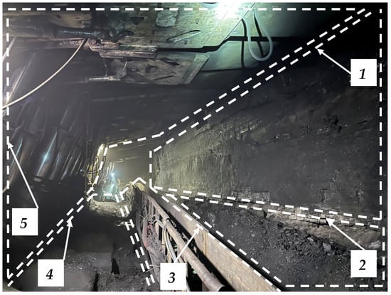
Figure 1.
View of the longwall, where its significant areas are marked: (1) coal sidewall, (2) path of the combine shearer, (3) scraper conveyor, (4) crew passage path, and (5) powered roof support.
The machines and devices included in the complex are characterised by the interrelationship of design and movement [31,47]. It results from the functionality of the mechanised complex and the geometric parameters of the wall, taking into account particular mining and geological conditions [17,48]. The coal miner wall complex is used in medium and high coal beds. The coal miner design allows for two mining heads to be placed at the beginning and end of the machine. The central part is where the electric and hydraulic parts are; it is connected to the arms in which the mining devices are built. A fundamental part of the machine is the haulage system [49,50]. The system was recently developed to increase the machine’s efficiency [51,52].
The wall complex with the planer is used in thin and medium bed coals. The main advantage of this technology is that it does not require an operator to move behind the machine, which is very cumbersome and dangerous for thin coal beds [53]. The design of the planers allows for selecting coal beds with easily and moderately extractable coal, providing a production volume comparable to that of walls using a coal miner with similar parameters. Currently, various types of stationary planers are used in the industry. The mining and loading body in the planer is a planer head drawn using a chain through drives fixed to the conveyor’s propulsive fuselage [54]. The work of the planer includes its head moving along the thrust of the scraper conveyor. The coal is mined employing the pulling force of the planer’s head [55,56].
Individual powered roof support types differ structurally, depending on the purpose. The purpose depends on the mining and geological conditions in which they will be used. These include the thickness and inclination of the coal bed, the roof control system (roof caving, backfill), and the type of cooperating mining machine. The powered roof support consists of many components designed to perform specific tasks. The structural part includes the foot piece, the cap piece, the shield, the lemniscate connectors, and the beams of the sliding systems. In contrast, the hydraulic force part includes actuators and shifters. The hydraulic control part includes control separating funnels, valve blocks, valves, wires, and fasteners (see Figure 2).
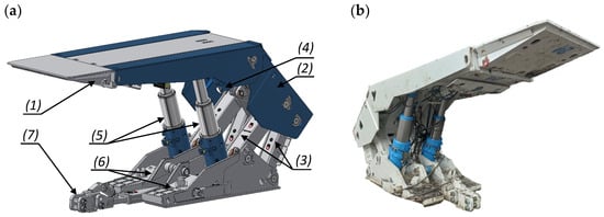
Figure 2.
View of the powered roof support section: design (a), canopy (1), shield support (2), lemniscate mechanism (3), ceiling support actuator (4), hydraulic actuators (5), floor base (6), beam of sliding system (7), and prototype (b).
The powered roof support’s most crucial parameter is the load-carrying capacity. This includes initial, operational, and nominal load-carrying capacity. The initial load-carrying capacity is characterised by the maximum pressure on the roof exerted with the section of the powered roof support expanded in the excavation. The pressure depends on the force exerted with the hydraulic actuators under the influence of the supply pressure and on the current height of the powered roof support’s operation. The area where the pressure is exerted is specified using the dimensions for the working load-carrying capacity of the powered roof support. The initial load-carrying capacity of the powered roof support can also be stated as a vertical component of the forces (with horizontal section adjustment) exerted with the hydraulic actuators under the influence of supply pressure, depending on the current working height of the powered roof support. Nominal load-carrying capacity is the maximum load-carrying capacity that a powered roof support can achieve under static load. It depends on the opening pressure of the safety valves in the resistance system of the hydraulic actuators of the powered roof support [57,58].
The working load-carrying capacity of powered roof support is a parameter that determines the border ability to transfer pressures using a roof opened for mining. It is measured as the pressure of the roof rocks on a single section of the powered roof support. It induces pressure equal to the overflow valve setting in the valve blocks protecting the actuators. The surface of the roof pressure on one section is determined using two perpendicular measurements: the partition of the section and the roof’s expansion limited by a coal sidewall and by the rear-edge break for the cap. The working load-carrying capacity of the powered roof support can also be specified as the vertical component of the forces (with a horizontal section setting). Roof rocks’ pressure on a single section of powered roof support causes a pressure equal to the setting of the overflow valves in the valve blocks protecting the actuators [59,60].
The requirements for powered roof support are constantly developing. The main reason is the increase in the depth of exploitation, which significantly affects the deterioration of mining and geological conditions. It results in an increasing pressure of the roof on the powered roof support. Maintaining the excavation roof becomes increasingly tricky. Research is still needed to improve the safety of people employed in the wall. Research is conducted to improve working comfort and adapt the powered roof support to changing mining and geological conditions. They require manufacturers and users to be highly involved in scientific and technological development [61,62].
The designed and manufactured prototype of the powered roof support section in the European Union is subject to tests based on harmonised standards. They are part of the product evaluation process, which verifies that the product meets the relevant requirements. Machinery Directive 2006/42/EC [63] includes detailed procedural characteristics related to the safety requirements for the powered roof support’s use. An integral part of the method evaluation is to verify that the powered roof support section meets the requirements of the ATEX Directive [64], and in the case of equipping it additionally with electrical and electronic equipment, it needs to comply with the Low Voltage Directive and Electrical Compatibility Directive [65]. There are currently three standards for powered roof support testing, which were updated in 2022. The first standard describes the general safety requirements [66]. The second standard contains information on the safety requirements of hydraulic actuators and other cylinders. The third standard contains requirements for the hydraulic control system of powered roof support [67]. The requirements describe the testing and qualification of the powered roof support. No standard would determine the suitability of powered roof support for the conditions of the threat of rockmass shocks.
The noise source in the powered roof support required an analysis regarding its operation parameters and environment. The data collection allowed for an objective assessment of its working conditions. In addition, information about the source effort (sound force, sound pressure, sound level) and the frequency spectrum of the source is necessary. These characteristics can be used to draw up an acoustic certificate of the machine. In general, the measurement of sound power is used to identify noise sources to minimise their impact on the environment. This information is also needed when conducting environmental assessments of industrial installations for noise emissions.
This paper aims to present the research results on the development of the method of sound power. A dynamic research station was used for this research. This method is intended to complement basic research to improve the safety of powered roof support sections.
2. Materials and Methods
Previous research and analyses have focused on obtaining the appropriate power in the actuator based on the pressure increase caused by a dynamic load in the sub-piston space. Examining the current European Directive [68] concerning the safety of machinery, its requirements concern defining the sound power level as a measure of the noise emission of machinery. The method of determining the sound power level shall be harmonised with that directive [69,70]. The tests complying with the Directive’s standards are part of the certification tests covered with the obligation of safety certification and the manufacturer’s obligation to issue a declaration of conformity. The test procedure shall use the methods described with the standards [71].
The reliability of the sound power level’s definition for machines depends on the standard reproducibility deviation and the required confidence level. The standard deviation of reproducibility is defined [72] as the standard deviation of the sound power levels under reproducibility conditions (repeated application of the same measurement method and source at different time intervals and under different measurement conditions). The standard deviation of the reproducibility of the test results of the sound power level of a particular method is related to the test conditions and the adopted measurement procedures and not to the source itself.
This is partly due to the difference between measurement laboratories and atmospheric conditions in the case of tests in open space. Another difference is the geometry of the test room or open space, the acoustic properties of the sound-reflecting surfaces, the sound absorption with the walls of the measuring room, the background noise, and the type and calibration of the measuring apparatus. There are also differences in the adopted measurement procedures: the location of the test source, the size and shape of the measuring surface, the number and location of the microphone on the measuring surface, the time of integration, and the determination of environmental corrections. The values of the standard deviation of reproducibility are given with the following standards [73,74]. In the case of a specific family of noise sources with similar dimensions, similar sound power spectra, and similar operating conditions, the standard deviations of reproducibility may be more minor. Therefore, the noise test procedure of a given machine type may predict a minor standard deviation.
If the results of appropriate inter-laboratory tests justify this, the author decided to conduct research and an analysis using the theory of the sound power of the sound source. It is defined as the total power of the sound wave emitted with the source. It is determined as a sound source using a closed surface and summing the streams of sound power through this surface. In this method, it is assumed that the absorption of the sound wave in the centre is negligible or the surface closely surrounds the source. In the case of air, the first condition is met for smaller distances. The formation of an acoustic wave is defined as a disturbance of density and pressure diverging in the centre in the form of a longitudinal wave, which is accompanied by vibrations of the particles of the centre. The centres in which such waves can move are elastic (solid, liquid, and gas). These disturbances involve transferring the mechanical energy through the vibrating particles of the centre (densification and dilution) without changing their average position. The resulting longitudinal wave is characterised by vibrations in the direction consistent with the direction of its propagation [75]. An example of a longitudinal wave is a sound wave.
The author proposes the following methodology for testing the sound power level of a hydraulic actuator of powered roof support (see Figure 3):
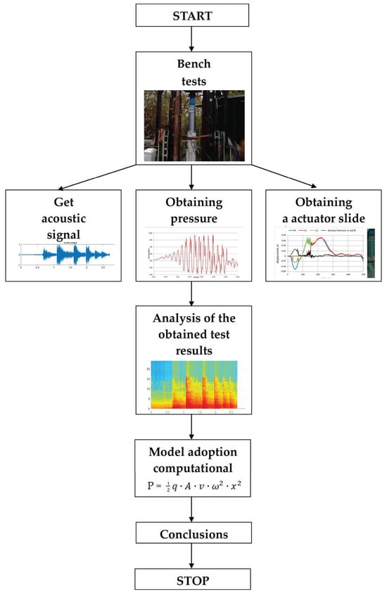
Figure 3.
Methodology of proceeding for acoustic power assessment.
- -
- hydraulic actuator tests in an open space;
- -
- using different heights of the load drop;
- -
- using different distances of the measuring surface from the source;
- -
- an analysis of test results based on the sound power dependence.
Adopted Calculation Model
For the adopted calculation model, the formula for the sound wave energy was used, which was divided by the time increase ∆t. The general formula for power is just energy divided by time:
For our considered case it will be
Assuming that is the speed of the sound wave, we obtain the formula
P—sound source power (W);
q—density of air (kg/m3);
∆x—distance travelled by the disturbance (m);
∆t—the time it takes the disturbance to travel the distance x (m);
x—the amplitude of shallow vibrations harmonically vibrating (m);
v—the speed of the sound wave equal to the quotient of the distance travelled by the disturbance (wave) to the time in which it occurs (m/s);
A—cross-sectional area perpendicular to the direction of the sound waves;
3. Results
During the exploitation of the coal bed using the powered roof support, the rockmass exerts a dynamic load on the machine. Inadequate protection against this phenomenon damages the structure, especially the hydraulic actuator. This research aims to map the dynamic load and determine the sound power. The test consisted of the free fall of the impact mass from a certain height and then determining a parameter defining the sound power based on the dynamic load during the bench tests (and in underground conditions of rockmass shocks). Free-falling mass as an impactor is a good example of the dynamic phenomena in affected rockmass.
Dynamic testing of hydraulic actuators for powered roof support can be carried out at three research centres in Europe. Two are in Poland: the Main Mining Institute and the KOMAG Institute of Mining Technology. The third centre is located in TLO Opava in the Czech Republic, where the author researched acoustic power. In this type of testing, the source of the load is a freely falling impact mass moving along the guides. In this position, a hoisting frame, loaded with an impact mass falling from a certain height, rests on the hydraulic actuator. The test result is recorded using a measuring system. A safety valve is connected to the sub-piston part of the actuator. Figure 4 shows the conduct of the study. The test consisted of setting the hydraulic actuator and loading it from a certain height. The drop test started at a height of 0.2 m and ended at a height of 0.9 m.
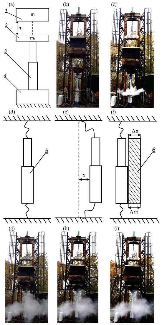
Figure 4.
Stand for testing hydraulic actuators of powered roof support loaded with mass impact: (a) construction of a test stand, 1—impact mass, 2—traverse, 3—hydraulic stand cylinder with pressure sensor, 4—foundation of the position; (b) view of the test bench located at TLO Opava in the Czech Republic; (c) view of the hydraulic actuator after the dynamic test; (d) actuator analysis, 5—vibrating rack surface after dynamic impact; (e) the amplitude of harmonic vibrations was created; (f–i) air layer formed after a dynamic impact; 6—air layer.
During testing, the actuator bends under the load impacting it. As a result of the accumulated pressure, the built-in safety valve for the sub-piston space drops the excess pressure. This is the only and most important protection of the actuator. During the tests, the safety valve’s task is to prevent exceeding the expected pressure value in the sub-piston space of the actuator. For this reason, a safety valve was used.
According to the scheme presented in Figure 4, the test consisted of putting the axial load on the hydraulic actuator with an impact mass (m) falling from a certain height (h) to a resting hoisting frame of a mass value at (mt). During the tests, the value of the impact mass (m) and the mass of the hoisting frame (mt) were constant. The impact mass was 20,000 kg, and the mass of the hoisting frame was 1800 kg. Tests were conducted for different heights.
The actual signal obtained during the bench tests was used to verify the sound power’s effectiveness. It was measured at a distance of about 5 m from the source using a microphone. The data were processed in the Matlab environment. Measurement duration reached up to 3 s at a sampling rate of 2.5 kHz. As you can see in the charts (see Figure 5), there are high-energy broadband pulses in the region of 0.5 to 1.5 s associated with decreasing mass shock. The resulting actual vibration signal contains various components with a complex structure. Components that could indicate damage occurring during the test are not visible in the signal regarding time due to the noise. The signal received in Figure 5 shows the most important results of bench tests.
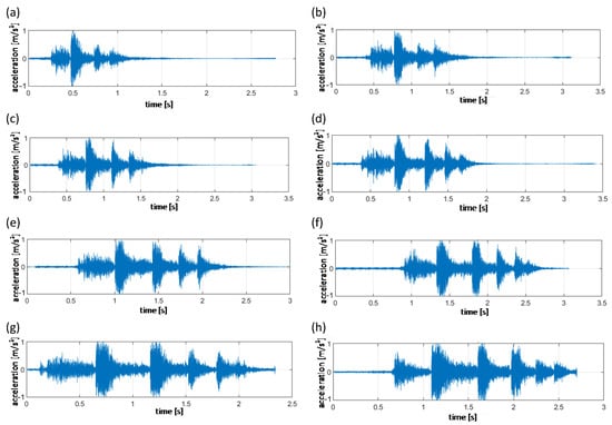
Figure 5.
The obtained test results for the resulting real signal, where the height of the drop for a particular measurement was as follows: (a) drop height of 0.2 m, (b) drop height of 0.3 m, (c) drop height of 0.4 m, (d) drop height of 0.5 m, (e) drop height of 0.6 m, (f) drop height of 0.7 m, (g) drop height of 0.8 m, and (h) drop height of 0.9 m.
The result of sound power positional tests for the sampled sound source is the resulting impact. In this case, the reverb time ranged from 0.5 to 1.5 s. Since the tests were performed in an open room, the reliability of the results is determined with the measuring distance and the sound propagation wave. If performed in a closed room, the sound wave propagation in the above test would be significantly different.
4. Discussion
The author performed a literature review on seismic events directly impacting the dynamic load of powered roof support. The hydraulic actuator was put under a load (see Figure 4) to determine its sound power. During the study, a number of different actual signals were obtained (see Figure 5) and in order to interpret them, an algorithm for finding the P wave was used [76].
Obtaining information about the sound power without detecting the moment of arrival of the P wave to the sensor is almost impossible. The main goal of the algorithm (where finding the P wave announces the moment of the beginning of a dynamic impact) is the high accuracy and automaticity of the method. In the research, an innovative method was used, including analysing the seismic signal. It is based on the analysis of the main components using the time–frequency representation of the signal (PCA—Principal Component Analysis).
The results were subjected to a time–frequency analysis for better accuracy in detecting changes in the signal structure. Figure 6 presents a spectrogram of the analysed dynamic data. The use of time–frequency representation makes it possible to observe the behaviour of the signal in regard to time and frequency. Introducing a change in the signal representation to the time–frequency map increases the computational complexity. Analysing the information about the energy flow in the signal is important from the point of detection of the P wave. It can cause a sudden change of value in the vibration signal. Therefore, the PCA method was used in the analysis, known for its high efficiency in reducing data dimensions while maintaining the greatest data variability.
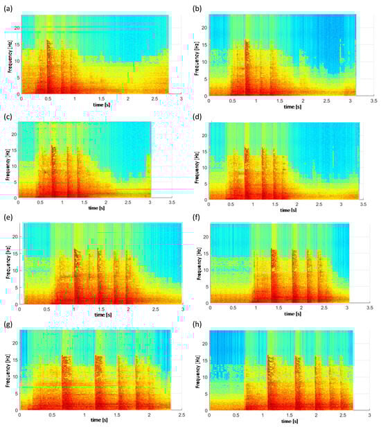
Figure 6.
Spectrogram of data from the obtained dynamic impact for the resulting real signal, where the drop height for each measurement was as follows: (a) drop height of 0.2 m, (b) drop height of 0.3 m, (c) drop height of 0.4 m, (d) drop height of 0.5 m, (e) drop height of 0.6 m, (f) drop height of 0.7 m, (g) drop height of 0.8 m, and (h) drop height of 0.9 m.
The goal of PCA is to rotate the local coordinate system to maximise variance in a new set of dimensions. The first dimension is characterised by the largest variance, the second dimension by the second-largest variance, etc. The analysis of the principal components is widely known in statistical analyses [76]. This transformed layout consists of new data values in a new set of dimensions. PCA is considered to be a method of dimensional reduction. The original data set is described mainly within the first few main components for the newly created feature space. They provide the most original information. Usually, the information contained in the first components is sufficient. This is because they contain a large amount of information.
In the studies conducted on the arrival of the P wave, it was noticed that there is a significant, abrupt change in variance. The time–frequency analysis is for the raw dynamic signal (see Figure 5). Using the PCA algorithm to extract the greatest variability in the data is important. For the PCA algorithm, a P wave detection technique was used based on the main principle of finding the maximum value on the derivative of the function’s first components of PCA. Determining the greatest variability in the data can be interpreted as the moment of arrival of the P wave. The method is intuitive and very effective. This method made it possible to analyse the research material. Figure 6 presents the spectrogram of the analysed data from the studies on the determination of sound power.
The results show that (see Figure 6) the alignment of the power intensity during impact is one of the criteria that can determine the usefulness or suitability of the hydraulic actuator of powered roof support. Objective measurement of this parameter is fraught with several difficulties, the greatest of which is the impossibility of accurately measuring the energy transmitted through the position beam. The sound power method can solve this problem by using the energy obtained to reference the power intensity for individual hydraulic shocks.
The results of the obtained measurements and the obtained sound power based on the relationships described in the adopted calculation model, listed in Table 1, are presented in Figure 7. The test results presented in this way constitute the entirety of research and research analyses on obtaining the acoustic power of the hydraulic support actuator based on stand tests.

Table 1.
Sound power occurring in a hydraulic actuator under load dynamic.
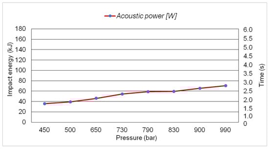
Figure 7.
Acoustic power graph for all bench tests.
5. Conclusions
In the context of the tests and analyses, it is necessary to amend the existing standards for the testing and design of powered roof support and to develop a standard for its protection under dynamic conditions concerning sound power. The lack of development of standards for testing and protecting the powered roof support against the dynamic impact of rockmass seems particularly incomprehensible, as in most cases, we are dealing with operation under dynamic impact. The conducted studies clearly show that the dynamic load is particularly disadvantageous due to the strong vibration amplitude, which regards the functionality of the control system of the powered roof support.
The sound power produced with the hydraulic actuator of the powered roof support during the bench tests must be greater than its load. During the impact load of the mass, the hydraulic actuator produces sound power. It results from the hydraulic actuator slipping to the limit value. Energy is generated due to the transfer of energy using the pile driver to the hydraulic actuator. The resulting energy is temporary because the safety valve dissipates it. The sound power is generated when the energy accumulates, which significantly affects the slip of the hydraulic actuator and the moment of dispersion through the safety valve. The most important cognitive conclusions are as follows:
- (1)
- It would be important to introduce a standard determining the utility of the powered roof support for the conditions of risk of rockmass tremors.
- (2)
- Manufacturers of powered roof support should extend their tests with the hydraulic impact sound power method.
- (3)
- The result of sound power tests based on the signal is more accurate than the pressure increase in the sub-piston space of the actuator.
- (4)
- The pressure increase in the sub-piston space causes the safety valve to operate against damage effects. The analysis of the signal generated during the dynamic impact can determine whether the behaviour of the safety valve is correct.
- (5)
- The sound power method based on the resulting signal should be considered in the analysis.
The results obtained from the bench tests made it possible to determine the sound power developed with the hydraulic actuator of a powered roof support due to dynamic load. In this paper, individual standards were analysed to develop the sound power method for studying the powered roof support’s hydraulic actuator. The sound power analysis is an additional requirement for studying powered roof support under adverse rockmass shocks (dynamic load) conditions. There are ambiguous provisions of the applicable standards and an increase in the threat of rockmass shocks.
The adoption of this proposal for universal application would have an impact on improving workplace safety. The research and the results indicate that the adopted methodology is correct. However, the research results do not exhaust the research problem of obtaining sound power. The proposed sound power method is based on positional (dynamic) tests and the energy of impact. This allows for an objective and accurate measurement of the sound power parameter. Thus, it can be of valuable help for both constructors and explorers of powered roof support.
Funding
This research received no external funding.
Institutional Review Board Statement
Not applicable.
Informed Consent Statement
Not applicable.
Data Availability Statement
Not applicable.
Conflicts of Interest
The author declares no conflict of interest.
References
- Bortnowski, P.; Gładysiewicz, L.; Król, R.; Ozdoba, M. Energy Efficiency Analysis of Copper Ore Ball Mill Drive Systems. Energies 2021, 14, 1786. [Google Scholar] [CrossRef]
- Bajda, M.; Błażej, R.; Hardygóra, M. Optimizing splice geometry in multiply conveyor belts with respect to stress in adhesive bonds. Min. Sci. 2018, 25, 195–206. [Google Scholar]
- Zimroz, P.; Trybała, P.; Wróblewski, A.; Góralczyk, M.; Szrek, J.; Wójcik, A.; Zimroz, R. Application of UAV in Search and Rescue Actions in Underground Mine—A Specific Sound Detection in Noisy Acoustic Signal. Energies 2021, 14, 3725. [Google Scholar] [CrossRef]
- Ziętek, B.; Banasiewicz, A.; Zimroz, R.; Szrek, J.; Gola, S. A Portable Environmental Data-Monitoring System for Air Hazard Evaluation in Deep Underground Mines. Energies 2020, 13, 6331. [Google Scholar] [CrossRef]
- Kawalec, W.; Suchorab, N.; Konieczna-Fuławka, M.; Król, R. Specific energy consumption of a belt conveyor system in a continuous surface mine. Energies 2020, 13, 5214. [Google Scholar] [CrossRef]
- Chuang, L.; Huamin, L.; Dongjie, J. Numerical simulation study on the relationship between mining heights and shield resistance in longwall panel. Int. J. Min. Sci. Technol. 2017, 27, 293–297. [Google Scholar] [CrossRef]
- Dlouhá, D.; Dubovský, V.; Pospíšil, L. Optimal calibration of evaporation models against Penman-Monteith equatíon. Water 2021, 13, 1484. [Google Scholar] [CrossRef]
- Huaiwei, R.; Desheng, Z.; Shixin, G.; Kai, Z.; Chenyang, X.; Ming, H.; Tijian, L. Dynamic impact experiment and response characteristics analysis for 1:2 reduced-scale model of hydraulic support. Int. J. Min. Sci. Technol. 2021, 3, 347–356. [Google Scholar]
- Gładysiewicz, L.; Król, R.; Kisielewski, W.; Kaszuba, D. Experimental determination of belt conveyors artificial friction coefficient. Acta Montan. Slovaca 2017, 22, 206–214. [Google Scholar]
- Adach-Pawelus, K.; Pawelus, D. Influence of Driving Direction on the Stability of a Group of Headings Located in a Field of High Horizontal Stresses in the Polish Underground Copper Mines. Energies 2021, 14, 5955. [Google Scholar] [CrossRef]
- Skrzypkowski, K.; Korzeniowski, W.; Zagórski, K.; Zagórska, A. Modified Rock Bolt Support for Mining Method with Controlled Roof Bending. Energies 2020, 13, 1868. [Google Scholar] [CrossRef]
- Doroszuk, B.; Król, R. Analysis of conveyor belt wear caused by material acceleration in transfer station. Min. Sci. 2019, 26, 189–201. [Google Scholar]
- Korbiel, T.; Stepien, B.; Batko, W.; Pawlik, P.; Blaut, J. Recognition of the 24-hour Noise Exposure of a Human. Arch. Acoust. 2017, 42, 601–607. [Google Scholar] [CrossRef]
- Prostański, D. Empirical Models of Zones Protecting against Coal Dust Explosion. Arch. Min. Sci. 2017, 62, 611–619. [Google Scholar] [CrossRef][Green Version]
- Wajs, J.; Trybała, P.; Górniak-Zimroz, J.; Krupa-Kurzynowska, J.; Kasza, D. Modern Solution for Fast and Accurate Inventorization of Open-Pit Mines by the Active Remote Sensing Technique—Case Study of Mikoszów Granite Mine (Lower Silesia, SW Poland). Energies 2021, 14, 6853. [Google Scholar] [CrossRef]
- Wodecki, J.; Góralczyk, M.; Krot, P.; Ziętek, B.; Szrek, J.; Worsa-Kozak, M.; Zimroz, R.; Śliwiński, P.; Czajkowski, A. Process Monitoring in Heavy Duty Drilling Rigs—Data Acquisition System and Cycle Identification Algorithms. Energies 2020, 13, 6748. [Google Scholar] [CrossRef]
- Bardzinski, P.; Jurdziak, L.; Kawalec, W.; Król, R. Copper ore quality tracking in a belt conveyor system using simulation tools. Nat. Resour. Res. 2020, 29, 1031–1040. [Google Scholar] [CrossRef]
- Grzesiek, A.; Zimroz, R.; Śliwiński, P.; Gomolla, N.; Wyłomańska, A. A Method for Structure Breaking Point Detection in Engine Oil Pressure Data. Energies 2021, 14, 5496. [Google Scholar] [CrossRef]
- Woźniak, D.; Hardygóra, M. Method for laboratory testing rubber penetration of steel cords in conveyor belts. Min. Sci. 2020, 27, 105–117. [Google Scholar] [CrossRef]
- Król, R.; Kisielewski, W. Research of loading carrying idlers used in belt conveyor-practical applications. Diagnostyka 2014, 15, 67–74. [Google Scholar]
- Bezyk, Y.; Dorodnikov, M.; Górka, M.; Sówka, I.; Sawiński, T. Temperature and soil moisture control CO2 flux and CH4 oxidation in urban ecosystems. Geochemistry 2023, 125989. [Google Scholar] [CrossRef]
- Qiao, S.; Zhang, Z.; Zhu, Z.; Zhang, K. Influence of cutting angle on mechanical properties of rock cutting by conical pick based on finite element analysis. J. Min. Sci. 2021, 28, 161–173. [Google Scholar] [CrossRef]
- Ji, Y.; Ren, T.; Wynne, P.; Wan, Z.; Zhaoyang, M.; Wang, Z. A comparative study of dust control practices in Chinese and Australian longwall coal mines. Int. J. Min. Sci. Technol. 2016, 25, 687–706. [Google Scholar] [CrossRef]
- Ralston, J.C.; Reid, D.C.; Dunn, M.T.; Hainsworth, D.W. Longwall automation: Delivering enabling technology to achieve safer and more productive underground mining. Int. J. Min. Sci. Technol. 2015, 25, 865–876. [Google Scholar] [CrossRef]
- Bazaluk, O.; Slabyi, O.; Vekeryk, V.; Velychkovych, A.; Ropyak, L.; Lozynskyi, V. A Technology of Hydrocarbon Fluid Production Intensification by Productive Stratum Drainage Zone Reaming. Energies 2021, 14, 3514. [Google Scholar] [CrossRef]
- Kawalec, W.; Błażej, R.; Konieczna, M.; Król, R. Laboratory Tests on e-pellets effectiveness for ore tracking. Min. Sci. 2018, 25, 7–18. [Google Scholar]
- Uth, F.; Polnik, B.; Kurpiel, W.; Baltes, R.; Kriegsch, P.; Clause, E. An innovate person detection system based on thermal imaging cameras dedicate for underground belt conveyors. Min. Sci. 2019, 26, 263–276. [Google Scholar]
- Bajda, M.; Hardygóra, M. Analysis of Reasons for Reduced Strength of Multiply Conveyor Belt Splices. Energies 2021, 14, 1512. [Google Scholar] [CrossRef]
- Peng, S.S.; Feng, D.; Cheng, J.; Yang, L. Automation in U.S. longwall coal mining: A state-of-the-art review. Int. J. Min. Sci. Technol. 2019, 29, 151–159. [Google Scholar]
- Hamříková, R.; Dlouhá, D. Video tutorials for students of the master’s program. In Open Education as a Way to a Knowledge Society; DisCo, Centre for Higher Education Studies: Praha, Czech Republic, 2017; pp. 446–451. [Google Scholar]
- Gabov, V.V.; Zadkov, D.A.; Babyr, N.V.; Xie, F. Nonimpact rock pressure regulation with energy recovery into the hydraulic system of the longwall powered support. Eurasian Min. 2021, 36, 55–59. [Google Scholar] [CrossRef]
- Juganda, A.; Strebinger, C.; Brune, J.F.; Bogin, G.E. Discrete modeling of a longwall coal mine gob for CFD simulation. Int. J. Min. Sci. Technol. 2020, 30, 463–469. [Google Scholar] [CrossRef]
- Toraño, J.; Diego, I.; Menéndez, M.; Gent, M. A finite element method (FEM)—Fuzzy logic (Soft Computing)—Virtual reality model approach in a coalface longwall mining simulation. Autom. Constr. 2008, 17, 413–424. [Google Scholar] [CrossRef]
- Hu, S.; Ma, L.; Guo, J.; Yang, P. Support-surrounding rock relationship and top-coal movement laws in large dip angle fully-mechanized caving face. Int. J. Min. Sci. Technol. 2018, 28, 533–539. [Google Scholar]
- Dlouhá, D.; Kozlová, K. Knowledge assessment of student’s high school mathematics. In Proceedings of the 18th Conference on Applied Mathematics, Bratislava, Slovakia, 5–7 February 2019; Volume 1, pp. 243–252. [Google Scholar]
- Bazaluk, O.; Velychkovych, A.; Ropyak, L.; Pashechko, M.; Pryhorovska, T.; Lozynskyi, V. Influence of Heavy Weight Drill Pipe Material and Drill Bit Manufacturing Errors on Stress State of Steel Blades. Energies 2021, 14, 4198. [Google Scholar] [CrossRef]
- Klishin, V.I.; Klishin, S.V. Coal Extraction from Thick Flat and Steep Beds. J. Min. Sci. 2010, 46, 149–159. [Google Scholar] [CrossRef]
- Juárez-Ferreras, R.; González-Nicieza, C.; Menéndez-Díaz, A.; Álvarez-Vigil, A.E.; Álvarez-Fernández, M.I. Measurement and analysis of the roof pressure on hydraulic props in longwall. Int. J. Coal Geol. 2008, 75, 49–62. [Google Scholar] [CrossRef]
- Buyalich, G.; Byakov, M.; Buyalich, K. Factors Determining Operation of Lip Seal in the Sealed Gap of the Hydraulic Props of Powered Supports. E3S Web Conf. 2017, 41, 1045. [Google Scholar] [CrossRef]
- Abu-Abed, F.; Pivovarov, K.; Zhironkin, V.; Zhironkin, S. Development of a Software Tool for Visualizing a Mine (Wellbore) in the Industrial Drilling of Oil Wells. Processes 2023, 11, 624. [Google Scholar] [CrossRef]
- Dubovský, V.; Dlouhá, D.; Pospíšil, L. The calibration of evaporation models against the Penman-Monteith equation on lake Most. Sustainability 2021, 13, 313. [Google Scholar] [CrossRef]
- Buyalich, G.; Byakov, M.; Buyalich, K.; Shtenin, E. Development of Powered Support Hydraulic Legs with Improved Performance. E3S Web Conf. 2019, 105, 3025. [Google Scholar] [CrossRef]
- Ralston, J.C.; Hargrave, C.O.; Dunn, M.T. Longwall automation: Trends, challenges and opportunities. Int. J. Min. Sci. Technol. 2017, 27, 733–739. [Google Scholar] [CrossRef]
- Frith, R.C. A holistic examination of the load rating design of longwall shields after more than half a century of mechanised longwall mining. Int. J. Min. Sci. Technol. 2015, 26, 199–208. [Google Scholar] [CrossRef]
- Zhao, X.; Li, F.; Li, Y.; Fan, Y. Fatigue Behavior of a Box-Type Welded Structure of Hydraulic Support Used in Coal Mine. Materials 2015, 8, 6609–6622. [Google Scholar] [CrossRef]
- Khayrutdinov, M.M.; Golik, V.I.; Aleksakhin, A.V.; Trushina, E.V.; Lazareva, N.V.; Aleksakhina, Y.V. Proposal of an Algorithm for Choice of a Development System for Operational and Environmental Safety in Mining. Resources 2022, 11, 88. [Google Scholar] [CrossRef]
- Smoliński, A.; Malashkevych, D.; Petlovanyi, M.; Rysbekov, K.; Lozynskyi, V.; Sai, K. Research into Impact of Leaving Waste Rocks in the Mined-Out Space on the Geomechanical State of the Rock Mass Surrounding the Longwall Face. Energies 2022, 15, 9522. [Google Scholar] [CrossRef]
- Luo, H.; Liang, S.; Yao, Q.; Hao, Y.; Li, X.; Wang, F.; Chen, X.; Yang, M. Mechanism and Application of Hydraulic Fracturing in the High-Level Thick and Hard Gangue Layer to Improve Top Coal Caving in Fully Mechanized Caving Mining of an Ultra-Thick Coal Seam. Minerals 2022, 12, 1605. [Google Scholar] [CrossRef]
- Gabov, V.V.; Zadkov, D.A.; Stebnev, A.V. Evaluation of structure and variables within performance rating of hydraulically powered roof sup-port legs with smooth roof control. Eurasian Min. 2016, 2, 37–40. [Google Scholar]
- Wang, D.; Li, R.; Cheng, J.; Zheng, W.; Shen, Y.; Zhao, S.; Wu, M. Research on the Calculation Model and Control Method of Initial Supporting Force for Temporary Support in the Underground Excavation Roadway of Coal Mine. Axioms 2023, 12, 948. [Google Scholar] [CrossRef]
- Krauze, K.; Mucha, K.; Wydro, T.; Pieczora, E. Functional and Operational Requirements to Be Fulfilled by Conical Picks Regarding Their Wear Rate and Investment Costs. Energies 2021, 14, 3696. [Google Scholar] [CrossRef]
- Hao, Y.; Li, M.; Wang, W.; Zhang, Z.; Li, Z. Study on the Stress Distribution and Stability Control of Surrounding Rock of Reserved Roadway with Hard Roof. Sustainability 2023, 15, 14111. [Google Scholar] [CrossRef]
- Rajwa, S.; Janoszek, T.; Prusek, S. Influence of canopy ratio of powered roof support on longwall working stability—A case study. Int. J. Min. Sci. Technol. 2019, 29, 591–598. [Google Scholar] [CrossRef]
- Huang, P.; Spearing, S.; Ju, F.; Jessu, K.V.; Wang, Z.; Ning, P. Control Effects of Five Common Solid Waste Backfilling Materials on In Situ Strata of Gob. Energies 2019, 12, 154. [Google Scholar] [CrossRef]
- Kotwica, K.; Stopka, G.; Kalita, M.; Bałaga, D.; Siegmund, M. Impact of Geometry of Toothed Segments of the Innovative KOMTRACK Longwall Shearer Haulage System on Load and Slip during the Travel of a Track Wheel. Energies 2021, 14, 2720. [Google Scholar] [CrossRef]
- Stoiński, K.; Mika, M. Dynamics of Hydraulic Leg of Powered Longwall Support. J. Min. Sci. 2003, 39, 72–77. [Google Scholar] [CrossRef]
- Buevich, V.V.; Gabov, V.V.; Zadkov, D.A.; Vasileva, P.A. Adaptation of the mechanized roof support to changeable rock pressure. Eurasian Min. 2015, 2, 11–14. [Google Scholar] [CrossRef]
- Stoiński, K. Mining Roof Support in Hazardous Conditions of Mining Tremors. In Collective Work for Editing Kazimierza Stoińskiego; The Central Mining Institute: Katowice, Poland, 2018. [Google Scholar]
- Babyr, N.; Babyr, K. To improve the contact adaptability of mechanical roof support. E3S Web Conf. 2021, 266, 03015. [Google Scholar] [CrossRef]
- Wang, J.; Wang, Z. Systematic principles of surrounding rock control in longwall mining within thick coal seams. Int. J. Min. Sci. Technol. 2019, 29, 591–598. [Google Scholar] [CrossRef]
- Świątek, J.; Janoszek, T.; Cichy, T.; Stoiński, K. Computational Fluid Dynamics Simulations for Investigation of the Damage Causes in Safety Elements of Powered Roof Supports—A Case Study. Energies 2021, 14, 1027. [Google Scholar] [CrossRef]
- Buyalich, G.; Buyalich, K.; Byakov, M. Factors Determining the Size of Sealing Clearance in Hydraulic Legs of Powered Supports. E3S Web Conf. 2017, 21, 3018. [Google Scholar] [CrossRef]
- Directive 2006/42/EC of the European Parliament. Available online: https://eur-lex.europa.eu/LexUriServ/LexUriServ.do?uri=OJ:L:2006:157:0024:0086:en:PDF (accessed on 1 October 2023).
- ATEX 2014/34/EU Equipment Directives of the European Parliament. Available online: https://eur-lex.europa.eu/legal-content/EN/TXT/?uri=CELEX:32014L0034 (accessed on 1 October 2023).
- PN-EN 1804-1:2021:5; Underground Mining Machinery—Safety Requirements for Powered Supports—Part 1: Support Sections and General Requirements. The Polish Committee for Standardization: Warsaw, Poland, 2021.
- PN-EN 1804-2:2021:5; Underground Mining Machinery—Safety Requirements for Powered Supports—Part 2: Stands and Other Actuators. The Polish Committee for Standardization: Warsaw, Poland, 2021.
- PN-EN 1804-2:2021:6; Machines for Underground Mining—Safety Requirements for Powered Supports—Part 3: Hydraulic and Electro-Hydraulic Control Systems. The Polish Committee for Standardization: Warsaw, Poland, 2021.
- Directive 98/97/WE of the European Parliament. Available online: https://eur-lex.europa.eu/LexUriServ/LexUriServ.do?uri=CONSLEG:1998L0079:20090807:en:PDF (accessed on 1 October 2023).
- EN ISO 3740:2019; Acoustics Determination of Sound Power Levels of Noise Sources Guidelines for the Use of Basic Standards. International Organization for Standardization: Geneva, Switzerland, 2019.
- EN ISO 9614-3:2002; Acoustics Determination of Sound Power Levels of Noise Sources Using Sound Intensity Part 3: Precision Method for Measurement by Scanning. International Organization for Standardization: Geneva, Switzerland, 2019.
- PN EN ISO 3744:2011; Acoustics—Determination of Sound Power Levels and Sound Energy Levels of Noise Sources Using Sound Pressure—Engineering Methods for an Essentially Free Field over a reflecting Plane. International Organization for Standardization: Geneva, Switzerland, 2011.
- PN-EN 27574-1:1997; Acoustics—Statistical Methods for Determining and Verifying Stated Noise Emission Values of Machinery and Equipment—Part 1: General Considerations and Definitions. International Organization for Standardization: Geneva, Switzerland, 2013.
- PN-EN ISO 3746; Acoustics—Termination of Sound Power Levels and Sound Energy Levels of Noise Sources Using Sound Pressure—Survey Method Using an Enveloping Measurement Surface Over a Reflecting Plane. International Organization for Standardization: Geneva, Switzerland, 2013.
- Lim, C.W.; Tong, L.H.; Li, Y.C. Theory of suspended carbon nanotube thinfilm as a thermal-acoustic source. J. Sound Vib. 2013, 332, 5451–5461. [Google Scholar] [CrossRef]
- Wodecki, J.; Hebda-Sobkowicz, J.; Mirek, A.; Zimroz, R.; Wyłomańska, A. Combination of Principal Component Analysis and Time-Frequency Representation for P-Wave Arrival Detection. Shock. Vib. 2019, 2019, 5961073. [Google Scholar] [CrossRef]
- Moore, B. Principal component analysis in linear systems: Controllability, observability, and model reduction. IEEE Trans. Autom. Control 1981, 26, 17–32. [Google Scholar] [CrossRef]
Disclaimer/Publisher’s Note: The statements, opinions, and data contained in all publications are solely those of the individual author(s) and contributor(s) and not of MDPI and/or the editor(s). MDPI and/or the editor(s) disclaim responsibility for any injury to people or property resulting from any ideas, methods, instructions, or products referred to in the content. |
Disclaimer/Publisher’s Note: The statements, opinions and data contained in all publications are solely those of the individual author(s) and contributor(s) and not of MDPI and/or the editor(s). MDPI and/or the editor(s) disclaim responsibility for any injury to people or property resulting from any ideas, methods, instructions or products referred to in the content. |
© 2023 by the author. Licensee MDPI, Basel, Switzerland. This article is an open access article distributed under the terms and conditions of the Creative Commons Attribution (CC BY) license (https://creativecommons.org/licenses/by/4.0/).