Design of the LIMELIGHT Test Rig for Component Testing for High-Temperature Thermal Energy Storage with Liquid Metals
Abstract
:1. Introduction
2. Materials Used for the Liquid Metal Loop
2.1. Liquid Metal: Lead (Pb)
2.2. Structural Material
2.3. Pre-Tests of Structural Material under Stagnant Conditions
3. Design of the LIMELIGHT Facility
3.1. Overall Layout of the Test Rig
3.2. Design of the Pipe System
3.3. Design of the Sump Tank
3.4. Design of the Pump Tank
3.5. Leak Detection and Design of the Safety Trough
3.6. Realization of Pressure Measurement
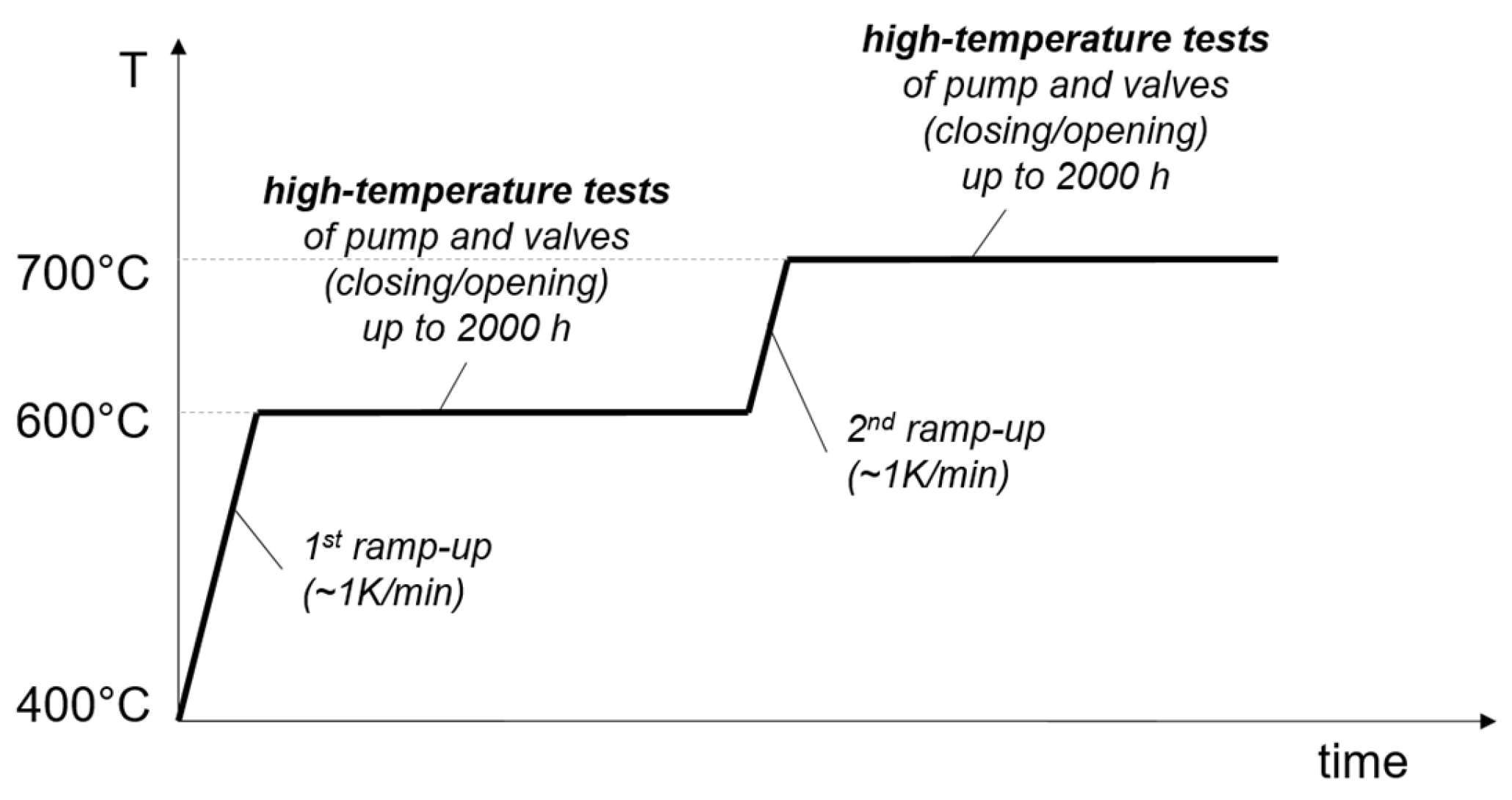
3.7. Planned Start-Up of the Loop and High-Temperature Experiments
4. Conclusions
Author Contributions
Funding
Data Availability Statement
Acknowledgments
Conflicts of Interest
References
- EERA White Paper, Industrial Thermal Energy Storage—Supporting the Transition to Decarbonise Industry. Available online: https://www.eera-set.eu/news-resources/3850-thermal-energy-storage-could-save-the-eu-over-500mt-co2-per-year.html (accessed on 23 August 2023).
- Profile of Heating and Cooling Demand in 2015. Technical Report D3.1, 2017, Heat Roadmap Europe. Available online: https://heatroadmap.eu/wp-content/uploads/2018/09/3.1-Profile-of-the-heating-and-cooling-demand-in-the-base-year-in-the-14-MSs-in-the-EU28-2.pdf (accessed on 23 August 2023).
- Steinmann, W.-D. Thermal Energy Storage for Medium and High Temperatures; Springer Fachmedien: Wiesbaden, Germany, 2022; pp. 77–114. [Google Scholar]
- Niedermeier, K.; Flesch, J.; Marocco, L.; Wetzel, T. Assessment of thermal energy storage options in a sodium-based CSP plant. Appl. Therm. Eng. 2016, 107, 386–397. [Google Scholar] [CrossRef]
- Laube, T.; Marocco, L.; Niedermeier, K.; Pacio, J.; Wetzel, T. Thermodynamic Analysis of High-Temperature Energy Storage Concepts Based on Liquid Metal Technology. Energy Technol. 2020, 8, 1900908. [Google Scholar] [CrossRef]
- Boerema, N.; Morrison, G.; Taylor, R.; Rosengarten, G. Liquid sodium versus Hitec as a heat transfer fluid in solar thermal central receiver systems. Sol. Energy 2012, 86, 2293–2305. [Google Scholar] [CrossRef]
- Pacio, J.; Wetzel, T. Assessment of liquid metal technology status and research paths for their use as efficient heat transfer fluids in solar central receiver systems. Sol. Energy 2013, 93, 11–22. [Google Scholar] [CrossRef]
- Pacio, J.; Singer, C.; Wetzel, T.; Uhlig, R. Thermodynamic evaluation of liquid metals as heat transfer fluids in concentrated solar power plants. Appl. Therm. Eng. 2013, 60, 295–302. [Google Scholar] [CrossRef]
- Fontalvo, A.; Guccione, S.; Wang, Y.; Wang, S.; Kee, Z.; Asselineau, C.-A.; Potter, D.; Venn, F.; Martinek, J.; Turchi, C.; et al. System-level comparison of sodium and salt systems in support of the Gen3 liquids pathway. AIP Conf. Proc. 2022, 2445, 030007. [Google Scholar]
- Müller-Trefzer, F.; Niedermeier, K.; Daubner, M.; Wetzel, T. Experimental investigations on the design of a dual-media thermal energy storage with liquid metal. Appl. Therm. Eng. 2022, 213, 118619. [Google Scholar] [CrossRef]
- OECD; NEA. Handbook on Lead-Bismuth Eutectic Alloy and Lead Properties, Materials Compatibility, Thermal-Hydraulics and Technologies, 2015th ed.; OECD/NEA: Paris, France, 2015. [Google Scholar]
- Ballinger, R.G.; Lim, J. An overview of corrosion issues for the design and operation of high-temperature lead- and lead-bismuth-cooled reactor systems. Nucl. Technol. 2004, 147, 418–435. [Google Scholar] [CrossRef]
- Zhang, J.; Li, N. Review of the studies on fundamental issues in LBE corrosion. J. Nuclear Mater. 2008, 373, 351–377. [Google Scholar] [CrossRef]
- Anderoglu, O.; Cakez, C.; Ghosh, S.; Talaat, K.; Lee, S.; Lee, Y.; Woloshun, K.A.; Kim, S.J.; Maloy, S.A.; Unal, C.; et al. Establishment of a Lead Loop Facility to Support Lead Cooled Fast Reactor Design. In TMS 2020 149th Annual Meeting & Exhibition Supplemental Proceedings; The Minerals, Metals & Materials Series; Springer: Berlin/Heidelberg, Germany, 2020. [Google Scholar]
- Talaat, K.; Hassan, M.M.; Cakez, C.; Ghosh, S.; Bohanon, B.; Woloshun, K.; Unal, C.; Anderoglu, O. Design of specimen holders for flow accelerated corrosion experiments in molten lead with numerical evaluation of pressure losses. Nucl. Eng. Des. 2021, 385, 111522. [Google Scholar] [CrossRef]
- Piazza, I.D.; Tincani, A.; Marinari, R.; Valdiserri, M.; Bassini, S.; Rinaldi, A.; Serra, M.; Antonelli, A.; Delfino, D. Conceptual design of the CSP lead demonstrator SOLEAD. Adv. Mater. Lett. 2020, 11, 1–7. [Google Scholar] [CrossRef]
- Rinaldi, A.; Barbieri, G.; Kosykh, E.; Szakalos, P.; Testani, C. Materials for high temperature liquid lead storage for concentrated solar power (CSP) air tower systems. Materials 2021, 14, 3261. [Google Scholar] [CrossRef] [PubMed]
- Kim, J.-S.; Dawson, A.; Wilson, R.; Venkatesan, K.; Stein, W. High-temperature heat transport and storage using LBE alloy for concentrated solar power system. In Proceedings of the ASME 2015 9th International Conference on Energy Sustainability, San Diego, CA, USA, 28 June–2 July 2015. [Google Scholar]
- Shi, H.; Azmi, R.; Han, L.; Tang, C.; Weisenburger, A.; Heinzel, A.; Maibach, J.; Stüber, M.; Wang, K.; Müller, G. Corrosion behavior of Al-containing MAX-phase coatings exposed to oxygen containing molten Pb at 600 °C. Corros. Sci. 2022, 201, 110275. [Google Scholar] [CrossRef]
- Deloffre, P.; Balbaud-Célérier, F.; Terlain, A. Corrosion behaviour of aluminized martensitic and austenitic steels in liquid Pb–Bi. J. Nucl. Mater. 2004, 335, 180–184. [Google Scholar] [CrossRef]
- ISO 5167-4:2022; Measurement of Fluid Flow by Means of Pressure Differential Devices Inserted in Circular Cross-Section CONDUITS Running Full—Part 4: Venturi Tubes. ISO: Geneva, Switzerland, 2022. Available online: https://www.iso.org/standard/79181.html (accessed on 6 October 2023).
- AD 2000 Code. TÜV Verband. Available online: https://www.ad-2000-online.de/en (accessed on 6 October 2023).

| Lead Properties | |
|---|---|
| Density | 10,196 kg/m3 |
| Thermal conductivity | 19.9 W/(m K) |
| Dynamic viscosity | 1.4 mPa s |
| Specific heat capacity | 142.1 J/(kg K) |
Disclaimer/Publisher’s Note: The statements, opinions and data contained in all publications are solely those of the individual author(s) and contributor(s) and not of MDPI and/or the editor(s). MDPI and/or the editor(s) disclaim responsibility for any injury to people or property resulting from any ideas, methods, instructions or products referred to in the content. |
© 2023 by the authors. Licensee MDPI, Basel, Switzerland. This article is an open access article distributed under the terms and conditions of the Creative Commons Attribution (CC BY) license (https://creativecommons.org/licenses/by/4.0/).
Share and Cite
Niedermeier, K.; Lux, M.; Purwitasari, A.; Weisenburger, A.; Daubner, M.; Müller-Trefzer, F.; Wetzel, T. Design of the LIMELIGHT Test Rig for Component Testing for High-Temperature Thermal Energy Storage with Liquid Metals. Processes 2023, 11, 2975. https://doi.org/10.3390/pr11102975
Niedermeier K, Lux M, Purwitasari A, Weisenburger A, Daubner M, Müller-Trefzer F, Wetzel T. Design of the LIMELIGHT Test Rig for Component Testing for High-Temperature Thermal Energy Storage with Liquid Metals. Processes. 2023; 11(10):2975. https://doi.org/10.3390/pr11102975
Chicago/Turabian StyleNiedermeier, Klarissa, Martin Lux, Anisa Purwitasari, Alfons Weisenburger, Markus Daubner, Franziska Müller-Trefzer, and Thomas Wetzel. 2023. "Design of the LIMELIGHT Test Rig for Component Testing for High-Temperature Thermal Energy Storage with Liquid Metals" Processes 11, no. 10: 2975. https://doi.org/10.3390/pr11102975
APA StyleNiedermeier, K., Lux, M., Purwitasari, A., Weisenburger, A., Daubner, M., Müller-Trefzer, F., & Wetzel, T. (2023). Design of the LIMELIGHT Test Rig for Component Testing for High-Temperature Thermal Energy Storage with Liquid Metals. Processes, 11(10), 2975. https://doi.org/10.3390/pr11102975


