Abstract
To solve the trajectory planning problem of the flexible manipulator under various constraints such as end-camera attitude, drive space, and obstacles during video inspection along a continuous path in narrow three-dimensional space, this paper proposes a time-optimal trajectory planning method from the initial configuration to the final configuration. The trajectory planning problem is transformed into a multi-constraint optimization problem. First, to realize continuous video inspection in an unstructured complex environment, by analyzing the geometric model of the two-segment flexible manipulator with a camera at the end, the pose constraints between the camera and the shooting surface are formulated by the space vector method, the driving constraints are formulated based on kinematics, and the obstacle constraints are formulated by space mapping. Then, a multi-constraint optimization model is constructed to generate the smooth trajectory of the drive cable of the flexible manipulator by minimizing the total time of continuous path motion. Compared with the conventional point-to-point collision avoidance planning solution method, this paper starts from the global perspective and investigates the less considered continuous path trajectory planning problem; also, the swarm intelligence algorithm artificial jellyfish search algorithm (JS) is employed to optimize the solution and find the minimum time trajectory conforming to a variety of complex constraints. Finally, a simulation is conducted with CoppeliaSim, and the continuous path video inspection experiment is carried out in the 500KV GIS (Gas Insulated Switchgear) equipment, the simulation and experimental results indicate that the planned drive cable trajectory is smooth and effective. In addition, each path point is tracked and obstacles are avoided safely. When the flexible manipulator moves along the whole path, the pose of the camera satisfies the relaxed attitude constrain The proposed method can guide the two-segment flexible manipulator to complete the continuous video inspection task of the GIS cavity wall and conductive column surface.
1. Introduction
A flexible manipulator moves by the deformation of the body and has good bending characteristics. Within the deformation range, it can flexibly change its shape in narrow working spaces and unstructured complex environments, demonstrating strong adaptability. The flexible manipulator is used to operate and maintain the equipment. At present, it has excellent application prospects in the fields of nuclear energy [1,2], aerospace [3], electric power energy [4], and medical [5,6].
For GIS (Gas Insulated Switchgear) cavity maintenance and operation tasks, due to the environmental constraints, the common solution is to use a flexible manipulator driven by cable/tendon. It has the characteristics of miniaturization, flexible operation, relatively simple driving, and easy modular transplantation, and it has been used to detect a narrow cavity in recent years [4,7]. In the above applications, besides the requirements for motor flexibility, the time to complete the operation or inspection is also critical. The redundant degree of freedom of the flexible manipulator enables the flexible manipulator to have high movement ability in the narrow space of the chaotic environment, but it also increases the complexity of the motion planning problem. Therefore, it is important to establish a trajectory planning method that comprehensively considers the structural characteristics and constraints of the flexible manipulator.
In an environment with obstacles, for a given end-continuous path, there is an infinite number of robot configurations, and as a result, the inverse kinematics and trajectory planning of redundant operators all choose the best configurations from infinite sets of configurations, thus formulating a problem of redundant solution. How to ensure the shortest movement time of the robot and satisfy the attitude constraints of the end camera and the driving constraints of the manipulator when moving between each path point is an urgent problem to be solved.
Due to the complexity of redundancy solving, some motion planning methods based on instructional learning are favored by relevant scholars. For example, reference [8,9,10] proposed a PTP motion planning framework of continuum manipulators based on instructional learning. In this framework, the two-segment continuum manipulator is guided by teleoperation to conduct PTP motion instructional learning, and model reference adaptive control is used to track and control the instructional motion path, thus achieving good results. In reference [11], the PTP motion trajectory is obtained based on the established interactive motion control framework, the PTP motion is reproduced by using the learning algorithm, and the method is further extended to multi-point trajectory planning. The experimental results verified the effectiveness of the framework based on instructional learning for the PTP motion of the continuum manipulator. Other scholars also used numerical solutions [12], geometric solutions [13], artificial neural networks [14], and other methods to study the PTP planning of flexible manipulators. Reference [15] proposed a real-time path planning method to solve the end path to the target position and the corresponding joint variables. Although the method can plan the end in real-time, it has no constraints on the attitude of the end. Reference [16] adopted the area clipping method to detect and clean foreign bodies in aircraft fuel tanks, but this method did not make sufficient use of space obstacle information, leading to a slow planning speed. In the work of reference [17], a shape-fitting algorithm was proposed to plan the end trajectory of a snake robot with multiple degrees of freedom, and the head-following strategy was adopted to realize the end navigation. Although this method does not require any time-consuming calculations, its accuracy is low due to the way of fitting. In the work of reference [18], a new method to calculate the performance of the new permutation was proposed, which was taken as the objective function of sequential quadratic programming (SQP), and then the optimization process was realized in the snake arm. Although the method has no requirements for environmental data and is in real-time, its terminal trajectory control precision is low; also, it fails to consider global information, so the attitude of the terminal to reach the target cannot be specified. After the study of the above reference, it is found that the above solutions cannot satisfy the requirements of continuous video inspection of GIS cavity walls and conductive column surfaces. Therefore, for the continuous inspection task, this paper considers the attitude constraints and driving constraints between any two points in a series of path points from a global perspective, thus ensuring that the normal line of the camera at the end of the flexible manipulator is as perpendicular to the shooting surface as possible. In this way, continuous video inspection of the surface to be detected can be realized.
To improve the working efficiency of the manipulator or reduce the energy loss, many scholars have investigated the optimization of some parameters in the robot motion process to improve the motion trajectory performance [19], including the optimal motion time [20], the optimal energy consumption [21], the optimal motion impact, and the optimal mixing [22]. However, no matter which type of parameter target is optimized, the purpose is to plan the optimal motion trajectory for the robot that satisfies various constraints, so that a specific task can be completed. To optimize the trajectory of the robot to achieve the minimum energy [23] and minimum torque [24], reference [25] proposed a method to optimize the torque at the joint and used a genetic algorithm to solve this problem. To minimize the total energy consumption of the robot, a new scheme was proposed in the reference [26] to realize the trajectory of the redundant manipulator. Generally, the motion time of the manipulator needs to be considered in the planning problem. Based on the optimization of energy consumption and motion time, a new trajectory planning method for the manipulator was developed in reference [27]. Additionally, Ding et al. [28] used neural networks to optimize the dynamics of redundant robots. Zhang et al. [29] proposed a method to minimize the applied torque of redundant robots based on a unified quadratic programming dynamic system. The above references indicates that few studies have been conducted on optimizing the continuous video inspection efficiency of the flexible manipulator in the narrow cavity. Therefore, to improve the complete video inspection efficiency on the surface of the cylindrical cavity and conductive column, from a global perspective, this paper optimizes the time of any PTP movement and takes the time to complete the video inspection of the whole path as the optimization parameter for trajectory planning. Compared with the PTP trajectory, the obtained continuous trajectory has improved maintenance efficiency.
Some studies try to transform the motion planning problem of the flexible manipulator into a constrained optimization problem, and then obtain the driver trajectory sequence satisfying the conditions by solving the optimization problem [30]. For example, reference [31] proposed a task space planning method based on an optimization solution. The method represents the quasi-static motion model of the manipulator as a potential energy minimization problem, represents the task space with inequality constraints, and calculates the driving force that makes the end move in the direction of the target according to the Jacobian matrix of the motion model. Experimental results indicate that this motion planning method can generate ideal terminal trajectories in the task space. Based on inverse differential kinematics, reference [32] formulated a constrained optimization problem for trajectory planning of flexible manipulators and solved the optimization problem with a fast gradient algorithm and a quadratic programming method. The analysis of the above references show that most planning methods based on optimization problems only consider simple constraints such as differential kinematics or task space, and other constraints in complex/congested non-structural environments are ignored, such as attitude constraints and collision constraints in the GIS cavity.
Currently, the common optimization algorithms include the gradient optimization algorithm and heuristic optimization algorithm. However, the optimization problem considered in this paper has many complex constraints, and the conventional solving methods cannot work effectively. Therefore, a more efficient swarm intelligence algorithm is needed to solve the optimization problem. Jui-Sheng Chou et al. [33], inspired by the foraging behavior of jellyfish in the ocean, proposed the artificial jellyfish search algorithm (JS algorithm). Meanwhile, references [33,34] shows that compared with other heuristic swarm intelligence algorithms, the artificial JS algorithm has faster search speed and solving accuracy when solving different optimization problems. Therefore, the JS algorithm is selected in this paper to solve the optimal trajectory optimization problem of the PTP movement time of a two-segment flexible manipulator with attitude constraints.
This paper proposes a time-optimal trajectory planning method for flexible manipulators moving along a multi-constraint continuous path and avoiding obstacles. Under the condition that the end of the flexible manipulators maintains the attitude constraint, the flexible manipulators can move from the initial configuration to the final configuration in the complex GIS cavity Then, the motion planning problem is presented as a global optimization problem, and the artificial JS algorithm is adopted to solve the optimization problem. The main innovations and contributions of this paper are as follows: (1) For the first time, a variety of constraints in the complex unstructured environment such as actuator constraints, obstacle constraints, and attitude constraints are considered to solve the trajectory. (2) Most scholars only focus on PTP trajectory planning. Considering the optimal continuous path time, this paper extends PTP collision avoidance planning to continuous path planning to improve the continuous video inspection efficiency of the manipulator. (3) A simulation model with dynamic property is established, and the flexible manipulator experiment platform is constructed. Meanwhile, Matlab, CoppeliaSim, and the prototype are used to conduct real experiments under the actual working conditions to verify the effectiveness of the proposed algorithm.
The rest of this paper is organized as follows: In Section 2, the task description and requirements, and the geometric model of the flexible manipulator prototype are presented. In Section 3, a kinematic model with multiple constraints is established. In Section 4, the time optimal trajectory planning algorithm is proposed. In Section 5, simulation and experimental verification are conducted, and the effectiveness of the method is discussed. Finally, Section 6 summarizes the contribution of this paper.
2. Problem Description
2.1. Task Description
In a narrow and unstructured environment such as GIS, a four-wheel omnidirectional mobile robot equipped with a two-segment flexible manipulator is used to perform video inspection inside the cavity. In the inspection and maintenance of the GIS equipment, continuous video inspection tasks are conducted on the inner wall of the GIS cavity and the surface of the conductive cylinder. Such tasks require that the center line of the camera at the end of the flexible manipulator should be as perpendicular as possible to the photographed surface (i.e., attitude constraints), thus obtaining the clearest actual situation of the photographed surface. Essentially, the continuous video inspection of the inner wall of the GIS cavity is a continuous path motion problem for the manipulator. For such a problem, besides the start and end poses, several path points need to be given. When the flexible manipulator moves, it needs to start from the starting point and then pass through the necessary points successively to reach the end pose and avoid obstacles.
As shown in Figure 1, in the continuous video inspection task of the inner wall of the GIS cavity, to accurately obtain the actual situation of the inner wall, it is required that the end camera of the arm of the GIS maintenance robot should move continuously along the circular arc of the inner wall of the GIS cavity, and the arm should not collide with the conductive column and wall. Due to the narrow and complex GIS environment, the problem of continuous video inspection with attitude constraints in this environment is transformed into an optimization problem, and the trajectory planning under the optimal time is considered.
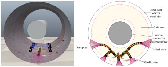
Figure 1.
The diagram of the intracavitary overhaul.
2.2. Geometric Model of the Flexible Manipulator
A GIS cavity is characterized by narrow and limited space, a complex assembly structure, many obstacles, and different layouts of phase lines in and out. Besides, GIS is a high-voltage device, and the inner wall is not allowed to be scratched. Therefore, operation and maintenance tools are required to not cause damage to the power equipment. Thus, the flexible manipulator adopts the rigid-flexible coupled composite structure, as shown in Figure 2. It is driven by six NITI alloy wires that are evenly distributed in each universal joint. The motion of the flexible manipulator is controlled by the action of the ball screw sliding table mechanism. The new flexible manipulator has the characteristics of a small volume, lightweight, and flexible movement.
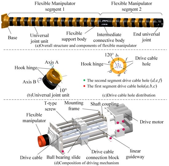
Figure 2.
The structure of the flexible manipulator.
A geometric model based on the piecewise constant curvature hypothesis is established in this paper for the cable-driven flexible manipulator, and virtual joint space variables are introduced to represent the rotation angle and the bending angle of the single segment joint, respectively. represents the length change of the drive cable, where i represents the number of current segment, and j represents the number of drive cable. In this case, the kinematic model of the linear drive flexible manipulator consists of two parts: one is the mutual mapping between the drive space composed of all the drive cables and the artificially introduced virtual joint space; the other is the mutual mapping between the artificially introduced virtual joint space and the working space of the manipulator end. Then, the forward kinematics relationship () can be summarized as the mapping () from the manipulator drive space to the virtual joint space and the mapping () from the virtual joint space to the working space of the manipulator end. Meanwhile, the inverse kinematic relationship () is the mapping () from the end workspace of the manipulator to the virtual joint space and the mapping () from the virtual joint space to the drive space of the manipulator, as shown in Figure 3. In the first two spaces, the subscript i represents the continuous joint of the first segment; the superscript j represents the number of drive cables required by the joint of this segment, and its value can be 3 or 4.

Figure 3.
Kinematic relation.
To establish the constraint model, the geometric model of the flexible manipulator is analyzed first. The manipulator body consists of two continuous joints and two translation segments. The base coordinate system is established at the center of the bottom of the first continuous joint, the coordinate system is established at the center of the end of the first continuous joint, the second continuous joint base coordinate system is established at the end of the first continuous joint, the second continuous joint end coordinate system is established at the end of the second continuous joint, and the robot workspace coordinate system is established at the center of the second continuous joint. Specifically, the positive direction of the X-axis of the base coordinate system points to the direction of the first drive cable hole, the positive direction of the Z-axis is the upward direction of the x-y plane of the vertical base coordinate system, and the positive direction of the Y-axis is determined following the right-hand rule. All other coordinate axes are the same as those in the base coordinate system . In Figure 4, are the bending angles of the first segment and the second segment with respect to the plane of their base coordinate systems, and the rotation angles are the rotation angles with respect to the X-axis of their base coordinate systems. Each segment of the designed two-segment flexible manipulator is driven by three driving lines. Therefore, in the base coordinate system of the first segment, a through hole is designed every 60° in the counterclockwise direction from the X-axis, with a total of six through holes to drive the movement of the two-segment flexible manipulator. The hole number ~ is the drive cable through hole of the first continuous joint, ~ is the drive cable through hole of the second continuous joint, and r is the distance from the center of the base coordinate system to the drive cable through hole.
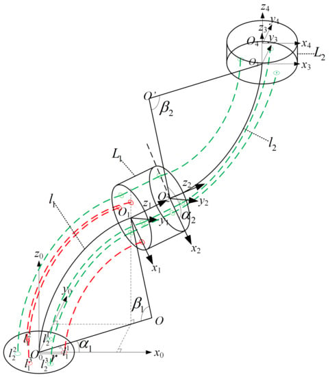
Figure 4.
The geometric model of the two-segment flexible manipulator.
3. Model of Constraints
When the two-segment flexible manipulator is used for video inspection of the continuous path of the inner wall surface of the GIS cavity, there are many constraints, such as relaxed attitude constraint, collision-free constraint, and driving constraint. The attitude constraint model of the center line and the photographed surface of the flexible manipulator is established by using the spatial vector representation method. Based on continuous path planning and aiming at time optimization, the trajectory optimization of PTP motion time with the attitude constraint in the GIS environment is presented in this paper. The optimal driving trajectory is provided for the continuous manipulator to perform a continuous video inspection of the inner wall of the GIS cavity, thus improving the working efficiency of the manipulator.
3.1. Relaxed Attitude Constraint
In continuous video inspection of the inner wall of the GIS cavity or the surface of the internal conductive column by using the flexible manipulator, the center line of the camera at the end of the flexible manipulator is always perpendicular to the positive section of the photographed surface under ideal conditions (the angle between the normal vector of the camera center line and the positive section of the photographed surface is ), i.e., the strict attitude constraints are satisfied. However, the actual situation is that the two-segment flexible manipulator is difficult to satisfy the strict attitude constraints in real motion. Therefore, this paper considers further relaxing the strict attitude constraint so that the center line of the camera at the end of the manipulator is always within a certain angle with the normal vector of the positive section of the photographed surface, i.e., the relaxed attitude constraint conditions are satisfied. The comparison of the strict attitude constraint model and the relaxed attitude constraint model is shown in Figure 5. Each of these constraints is described mathematically below.
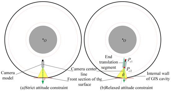
Figure 5.
The attitude constraint model.
The above attitude constraint problem can be expressed in mathematics by a space vector method. Since the camera is fixed on the central axis of the translation segment at the end of the two-segment flexible manipulator, two points and on the central axis at the end of the translation segment in Figure 5 can form a vector to represent the center line of the camera. The normal vector of the tangent face of the photographed surface can be represented by the vector composed of the center O of the GIS equipment and the endpoint of the manipulator. Then, the angle between the vector of the center line of the camera and the normal vector of the positive section of the photographed surface can be obtained by the following formula:
Note that when calculating the space coordinates of the vector , it should be ensured that points O and are on the same circular section, i.e., the two points in the manipulator base coordinate system have the same Z-axis values. When the surface of the conductive cylinder needs to be checked, the normal vector of the positive section of the photographed surface should be .
Therefore, in the trajectory optimization problem of PTP motion of any two adjacent points in a continuous path, the angle between the center line vector of the camera at the end of the manipulator and the normal vector of the positive section of the photographed surface should satisfy the relaxation pose constraint at any time t, namely:
where is the angle threshold, and it can be adjusted according to the actual situation.
3.2. Collision-Free Constraint
In the optimization of the PTP trajectory of any two adjacent points in the continuous path, it is necessary to ensure that the forward kinematics arm corresponding to the trajectory planned by the drive cable at time t cannot collide with the obstacle environment. In this paper, the joint space to three-dimensional space mapping is used to solve the collision-free constraint problem. Firstly, the forward kinematic relation is exploited to obtain the discrete point of the arm shape of the two-segment flexible manipulator in three-dimensional space, as shown in Equation (3):
Then, the distance between each discrete point and the GIS center O is calculated, and the maximum distance and minimum distance are determined so that the following requirements are met:
3.3. Driving Constraint
Due to the limitation of T-type screw length, in addition to the above constraints, it is also necessary to satisfy the constraint for the position of the drive cable of the two-segment cable-driven flexible manipulator. In addition to the position constraint, due to the limitations of motor speed and acceleration length, velocity and acceleration constraints of the drive cable should also be satisfied at any time in the trajectory planning results, as shown below.
The constraint of position:
where is the change value of the length of the six drive wires over time, and they can be obtained from Equations (A1)–(A3) in the Appendix A.
The constraint of velocity:
where is the change value of the speed of the six drive cables over time, and they can be obtained from Equation (A4) in the Appendix A.
The constraint of acceleration:
where, is the change value of the acceleration of the six driving lines with time, and they can be calculated by the time derivative of Equation (A4) in the Appendix A.
4. Time Optimization Programming Algorithm
In the continuous video inspection task of a two-segment flexible manipulator, the continuous path can be decomposed into several groups of PTP motion. Thus, the study of PTP trajectory optimization with attitude constraints can guide the motion control of continuous video inspection tasks. Assume that the continuous path of the video inspection task of the flexible manipulator is , take any two adjacent points and in the path as examples, and select the path point as the starting point and the path point as the target point. The interpolation time of the motion of the flexible manipulator from the starting point to the target point is , and the end attitude, collision, and drive constraints must be satisfied in the intermediate process. For the PTP movement from and , the optimization problem is formulated with time optimization as the goal:
where, represents the total motion time from the starting point to the target point, and represents the time interpolation sequence of the intermediate process from the starting point to the target point. in the collision constraint includes the minimum distance and maximum distance .
When Equation (8) obtains the minimum value, the minimum time of the PTP motion satisfying the constraint can be obtained, namely:
In this case, the trajectory of the drive cable corresponding to the shortest motion time between the starting point and the target point is the optimal trajectory of the flexible manipulator satisfying the attitude constraint, namely:
where represents the trajectory change sequence of the six drive cables.
According to the above method, when the motion time between any two adjacent points in the continuous path of video inspection is the shortest, the whole moving process of continuous video inspection can be guaranteed to be the shortest. In the trajectory optimization problem of this paper, quintic polynomial trajectory planning is conducted between any two adjacent points in the continuous path according to the motion time. The trajectory planning results must satisfy the constraints of attitude, no collision, and drive at any time.
The JS algorithm is adopted to solve the optimal trajectory optimization problem of the continuous path motion time of the two-segment flexible manipulator with attitude constraints in this paper. The flow chart of the solution is as follows:
To solve the above optimization problem, the JS algorithm is used to solve the time-optimal trajectory optimization problem under the attitude constraint for any two adjacent path points in the continuous path of the inner wall video inspection task. Assume that the motion time between any two adjacent waypoints is t. To minimize the total motion time, the motion time t of any two adjacent waypoints should be as small as possible. Therefore, the exercise time t is taken as the optimization parameter, and the fitness function is established as follows:
When the motion time between two adjacent path points is known, the quintic polynomial method is employed for trajectory planning. The specific method is as follows: the continuous path is checked by the video on the inner wall of the GIS cavity to determine the positions of two adjacent path points. Assuming that both the velocity and acceleration of the two points are 0 and the movement time is t, the planned polynomial trajectory can be obtained by substituting these parameters into Equation (A5) in the Appendix A. Then, whether the planned trajectory satisfies all constraints is determined. If all constraints are satisfied, the planned trajectory is regarded as a feasible solution, and then the motion time is optimized until the iterative process is removed. When the iteration is completed, the trajectory with the shortest time is output.
In Figure 6, it should be noted that the position with the lowest fitness value is not selected as the best position when initializing the JS and the optimal position. Since the trajectory planning results of the location with the smallest fitness value may not satisfy all the constraints, this paper selects the location with the largest fitness value as the best location.
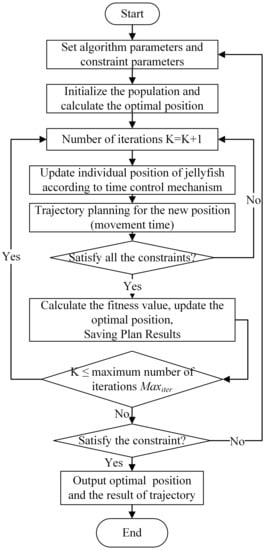
Figure 6.
The flow chart of the solution process.
5. Analysis of Simulation and Experiment Results
The simulation is conducted on a desktop computer running the 64-bit Windows10 operating system. The processor is Inter(R) Core(TM) i7-9700@3.00GHz 8, the graphics card is NVIDIA GeForce GTX1660Ti, the simulation software is MATLAB R2021a, and robot simulation software is CoppeliaSim 4.0.0.
To verify the actual effect of the JS algorithm in solving the trajectory optimization problem of a flexible manipulator with attitude constraints, the JS algorithm is used to solve the problem following the optimization solution process presented in Figure 6. Firstly, the continuous path points that the two-segment flexible manipulator needs to pass through during the video inspection of the inner wall of the GIS cavity are illustrated, and the continuous path is presented in the form of terminal pose, where the first three numbers represent the in the base coordinate system, and the last three numbers represent the RPY Angle., as shown in Table 1.

Table 1.
The video inspection of the internal wall continuous path point sequence in the GIS cavity.
Since the continuous path points of video inspection are given in the form of terminal points, the trajectory planning needs to be conducted in the virtual joint space. Therefore, before the trajectory optimization of two adjacent points in the continuous path, the inverse kinematics solution based on particle swarm optimization should be exploited to obtain the mapping from the workspace to the virtual joint space to solve the inverse kinematics. In this way, the virtual joint sequence corresponding to the continuous path is obtained.
In the optimization calculation with the JS algorithm, the parameters are set as follows: the population number is set to 20, the ocean current motion factor , the motion coefficient , the upper boundary of position , the lower boundary , and the maximum number of iterations . Among the constraints, angle threshold , the drive position constraint mm, the velocity constraint mm/s, and the acceleration constraint = 0.2 mm/. After obtaining the virtual joint sequence of the continuous path, the JS algorithm is used to optimize the trajectory of the two adjacent path points in the path, and the shortest motion time and solving time between the corresponding two points are obtained, as shown in Table 2.

Table 2.
The JS algorithm to obtain the shortest motion time and solving time for two path points.
It can be seen from Table 2 that according to the given continuous path for video inspection of the inner wall of the GIS cavity, the minimum total motion time of the trajectory satisfying all constraints is about 166 s. Meanwhile, the optimal drive cable trajectory for continuous video inspection of the inner wall of the GIS cavity can be obtained by connecting the drive cable trajectory from path point 1 to 11, as shown in Figure 7. By taking the time-optimal trajectory as the control input of the flexible manipulator, the two-segment flexible manipulator of the GIS maintenance robot can be controlled to perform video inspection according to the given continuous path points.

Figure 7.
The trajectory planning results of the drive cable.
5.1. Verification by Experiment
To verify the effectiveness of the JS algorithm in solving the trajectory optimization problem of the flexible manipulator with attitude constraints, the time-optimal drive cable trajectory obtained in the previous section is used for the motion control simulation and prototype experiment. The simulation involves two parts: Matlab numerical simulation and CoppeliaSim virtual model simulation. The experiment is conducted in 500KV GIS equipment by using the developed two-segment flexible manipulator prototype (Figure 8).
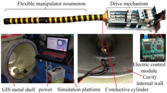
Figure 8.
The prototype and experimental environment.
The time-optimal drive cable trajectory obtained by the optimization algorithm is used as the input to control the two-segment flexible manipulator, and the experiment is conducted according to the simulation and experimental schematic diagram shown in Figure 9. In the process of simulation and experiment, when the target drive cable is positive, the DC motor should draw the line towards the base of the flexible manipulator; when the target drive cable is negative, the motor should release the line towards the end of the manipulator. Since pure numerical simulation is conducted in Matlab, the Matlab simulation results are taken as the reference target to compare the virtual simulation of the manipulator motion control with the experimental results of the prototype. Meanwhile, to test whether the camera at the end of the flexible manipulator arm can capture specific conditions in the environment during its movement, small squares with different colors are added to the surface of the GIS simulation body wall in CoppeliaSim to simulate small foreign bodies in the actual environment.

Figure 9.
The scheme of the motion control simulation experiment.
5.2. Analysis of Experimental Results
After the completion of Matlab simulation, CoppeliaSim simulation, and GIS prototype experiment, the simulation and experimental results are compared. Figure 10 shows the comparison of the motion timing sequence obtained by simulation and prototype experiment. The transparent arm shape in the motion timing sequence obtained by Matlab represents continuous video inspection path points, and the arm shape of the camera field marked with red at the end is the actual path in motion. It can be seen from the figure that from t = 0 s to t = 166.34 s, the two-segment continuous manipulator can pass through the intermediate waypoint successively to complete the continuous video inspection of the inner wall surface of the GIS cavity. During the whole process, there is no collision between the manipulator and the environment. Meanwhile, in the whole process, the center line of the camera at the end of the manipulator should be as perpendicular as possible to the normal section of the inspected surface to satisfy the constraint of relaxed posture. The upper right picture of the CoppeliaSim simulation sequence diagram in Figure 10 records the camera field of view at the end of the flexible manipulator during the moving process, indicating that the trajectory obtained by the JS algorithm can be used for video inspection tasks.
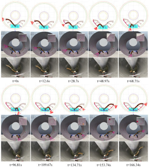
Figure 10.
Comparison of the motion sequence obtained by Matlab (top), CoppeliaSim (middle), and simulation and prototype experiment (bottom).
Besides the motion sequence diagram, the trajectory of the endpoint of the manipulator, the spatial coordinates of the endpoint, the virtual joint variables, and the changes of the drive cable are compared and analyzed. The experimental environment of the prototype is a complex and narrow GIS cavity. The motion trajectories of the endpoints of the manipulator and the changes of the virtual joint variables cannot be collected by appropriate external equipment, but only the changes of the six driving wires with the movement time can be collected by the prototype electronic control system. Figure 11 and Figure 12 illustrate the comparison of the end track and coordinate changes in the motion simulation of the continuous video inspection trajectory of the inner wall of the GIS cavity. It can be seen from the figures that the end trajectory of the virtual simulation is almost the same as the target trajectory (the Matlab result).
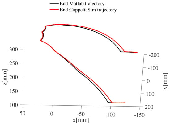
Figure 11.
The trajectory of the end.
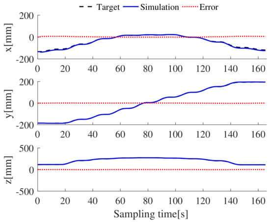
Figure 12.
The change in the space coordinates of the endpoints.
The length of the whole flexible manipulator is 304 mm. Figure 12 shows that the average error of the X-axis is 3.22 mm, the average error of the Y-axis is 1.45 mm, and the average error of the Z-axis is 2.12 mm. Virtual joint variables play an indirect role in trajectory optimization, and they can directly display the arm shape state of the two-segment flexible manipulator. Therefore, the target joint is also compared with the CoppeliaSim simulation results, as shown in Figure 13 and Figure 14. Meanwhile, the change of drive cable is the only data that can be collected from the prototype experiment, and it is compared with the virtual simulation results and target values, as shown in Figure 15 and Figure 16. It can be seen from the figures that the simulation value, the experimental value, and the target drive cable length exhibit the same variation trend, but there is an unknown error between them and the target value. It is suggested that the error of the virtual simulation results comes from the error of the virtual model and the error of the open loop control, while the error of the prototype experiment may be caused by the mechanical error of the prototype and the blockage of the DC motor. The simulation and experimental results indicate that the proposed method can solve the trajectory optimization problem of the flexible manipulator with attitude constraints.
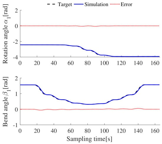
Figure 13.
The comparison of the virtual joints in the continuous segment 1.
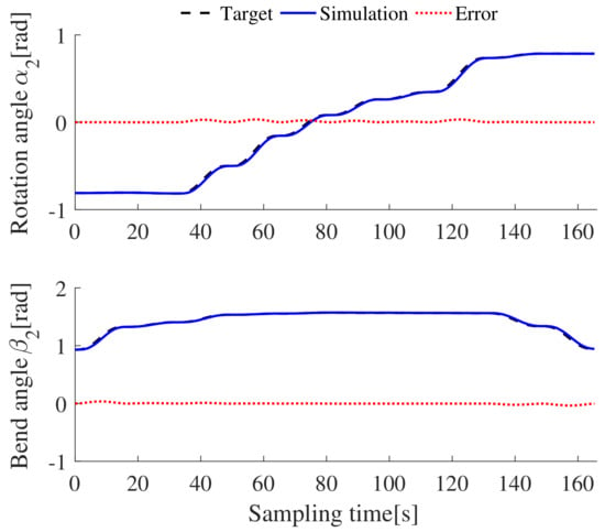
Figure 14.
The comparison of the virtual joints in the continuous segment 2.
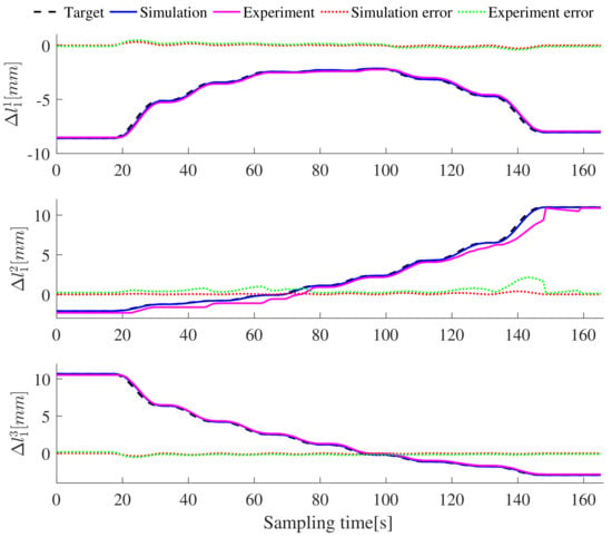
Figure 15.
Length change of ~ in segment 1.
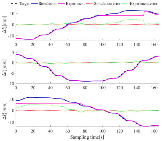
Figure 16.
Length change of ~ in segment 2.
6. Conclusions
This paper discusses the time-optimal trajectory planning problem of the flexible manipulator moving along a multi-constraint continuous path and avoiding obstacles in the maintenance task of the GIS cavity. The constrained optimization problem is formulated to optimize the movement time of any two adjacent points in the continuous path. Then, the JS algorithm is employed to solve the optimization problem. According to the solution process, the optimal driving cable trajectory of the optimization problem satisfying the constraints is obtained. Finally, the optimal drive cable trajectory is used as the input for the motion control simulation and prototype experiment for verification. The simulation and experimental results indicate that the proposed solution can guide the two-segment flexible manipulator to complete the continuous video inspection task of the inner wall surface of the GIS cavity. Moreover, when the flexible manipulator moves along the whole path, the pose of the camera satisfies the relaxed attitude constraint, and the average tracking error of in three-dimensional space is about 1% of the arm length. This method can be well extended to other flexible manipulators. The main work in the future is to extend its application to various complex surfaces.
Author Contributions
Conceptualization, S.D.; methodology, writing, visualization, Q.X.; investigation, Y.C.; Validation, Y.Z.; supervision, G.X. All authors have read and agreed to the published version of the manuscript.
Funding
This work was partially supported by the Scientific and Technical Programs of Sichuan Province of China under Grant 23NSFSC1186.
Institutional Review Board Statement
Not applicable.
Informed Consent Statement
Not applicable.
Data Availability Statement
Not applicable.
Conflicts of Interest
The authors declare no conflict of interest.
Appendix A
References
- Burgner-Kahrs, J.; Rucker, D.C.; Choset, H. Continuum robots for medical applications: A survey. IEEE Trans. Robot. 2015, 31, 1261–1280. [Google Scholar] [CrossRef]
- Shi, C.; Luo, X.; Qi, P.; Li, T.; Song, S.; Najdovski, Z.; Fukuda, T.; Ren, H. Shape sensing techniques for continuum robots in minimally invasive surgery: A survey. IEEE Trans. Biomed. Eng. 2017, 64, 1665–1678. [Google Scholar] [CrossRef] [PubMed]
- Hwang, M.; Kwon, D.S. K-FLEX: A flexible robotic platform for scar-free endoscopic surgery. Int. J. Med. Robot. 2020, 16, 1–14. [Google Scholar] [CrossRef]
- Ma, C.; Zhao, T.; Xiang, G.; Ren, J.; Chen, Y.; Dian, S. End positioning control of flexible manipulator based on inverse kinematics. J. Mech. Eng. 2021, 64, 1665–1678. [Google Scholar]
- Chitalia, Y.; Deaton, N.J.; Jeong, S.; Rahman, N.; Desai, J.P. Towards FBG-based shape sensing for micro-scale and meso-scale continuum robots with large deflection. IEEE Robot. Autom. Lett. 2020, 5, 1712–1719. [Google Scholar] [CrossRef]
- Nahar, D.; Yanik, P.M.; Walker, I.D. Robot tendrils: Long, thin continuum robots for inspection in space operations. In Proceedings of the 2017 IEEE Aerospace Conference, Big Sky, MT, USA, 4–11 March 2017. [Google Scholar]
- Neumann, M.; Burgner-Kahrs, J. Considerations for follow-the-leader motion of extensible tendon-driven continuum robots. In Proceedings of the 2016 IEEE International Conference on Robotics & Automation, Stockholm, Sweden, 16–21 May 2016. [Google Scholar]
- Seleem, I.; El-Hussieny, H.; Assal, S. Development of a demonstration-guided motion planning for multi-section continuum robots. In Proceedings of the 2018 IEEE International Conference on Systems, Man, and Cybernetics, Miyazaki, Japan, 7–10 October 2018. [Google Scholar]
- Seleem, I.A.; Assal, S.F.M.; Ishii, H.; El-Hussieny, H. Demonstration-guided pose planning and tracking for multi-section continuum robots considering robot dynamics. IEEE Access 2019, 7, 166690–166703. [Google Scholar] [CrossRef]
- Seleem, I.A.; El-Hussieny, H.; Assal, S.F.M.; Ishii, H. Development and stability analysis of an imitation learning-based pose planning approach for multi-section continuum robot. IEEE Access 2020, 8, 99366–99379. [Google Scholar] [CrossRef]
- Mayer, A.; Müller, D.; Raisch, A.; Hildebrandt, A.; Sawodny, O. Demonstration-based programming of multi-point trajectories for collaborative continuum robots. IFAC-PapersOnLine 2019, 52, 513–518. [Google Scholar] [CrossRef]
- Song, S.; Li, Z.; Meng, Q.H.; Yu, H.; Ren, H. Real-time shape estimation for wire-driven flexible robots with multiple bending sections based on quadratic Bézier curves. IEEE Sens. J. 2015, 15, 6326–6334. [Google Scholar] [CrossRef]
- Giorelli, M.; Renda, F.; Ferri, G.; Laschi, C. A feed-forward neural network learning the inverse kinetics of a soft cable-driven manipulator moving in three-dimensional space. In Proceedings of the 2013 IEEE/RSJ International Conference on Intelligent Robots and Systems, Tokyo, Japan, 3–7 November 2013. [Google Scholar]
- Godage, I.S.; Branson, D.T.; Guglielmino, E.; Caldwell, D.G. Path planning for multisection continuum arms. In Proceedings of the 2012 International Conference on Mechatronics & Automation, Chengdu, China, 5–8 August 2012. [Google Scholar]
- Ataka, A.; Peng, Q.; Liu, H.; Althoefer, K. Real-time planner for multi-segment continuum manipulator in dynamic environments. In Proceedings of the 2016 IEEE International Conference on Robotics & Automation, Stockholm, Sweden, 16–21 May 2016. [Google Scholar]
- Niu, G.; Zheng, Z.; Gao, Q. Collision free path planning based on region clipping for aircraft fuel tank inspection robot. In Proceedings of the 2014 IEEE International Conference on Robotics and Automation, Hong Kong, China, 31 May–7 June 2014. [Google Scholar]
- Mohammad, A.; Russo, M.; Fang, Y.; Dong, X.; Axinte, D.; Kell, J. An efficient follow-the-leader strategy for continuum robot navigation and coiling. IEEE Robot. Autom. Lett. 2021, 6, 7493–7500. [Google Scholar] [CrossRef]
- Palmer, D.; Cobos-Guzman, S.; Axinte, D. Real-time method for tip following navigation of continuum snake arm robots-ScienceDirect. Rob. Rob. Auton. Syst. 2014, 62, 1478–1485. [Google Scholar] [CrossRef]
- Kim, J.; Croft, E.A. Online near time-optimal trajectory planning for industrial robots. Robot. Comput. Integr. Manuf. 2019, 58, 158–171. [Google Scholar] [CrossRef]
- Xidias, E.K. Time-optimal trajectory planning for hyper-redundant manipulators in 3D workspaces. Robot. Comput. Integr. Manuf. 2018, 50, 286–298. [Google Scholar] [CrossRef]
- Paes, K.; Dewulf, W.; Vander Elst, K.; Kellens, K.; Slaets, P. Energy efficient trajectories for an industrial ABB robot. Procedia Cirp. 2014, 15, 105–110. [Google Scholar] [CrossRef]
- Frego, M.; Bevilacqua, P.; Divan, S.; Zenatti, F.; Palopoli, L.; Biral, F.; Fontanelli, D. Minimum time-minimum jerk optimal traffic management for AGVs. IEEE Robot. Autom. Lett. 2020, 5, 5307–5314. [Google Scholar] [CrossRef]
- Mahdavian, M.; Shariat-Panahi, M.; Yousefi-Koma, A.; Ghasemi-Toudeshki, A. Optimal trajectory generation for energy consumption minimization and moving obstacle avoidance of a 4DOF robot arm. In Proceedings of the 2015 3rd RSI International Conference on Robotics and Mechatronics, Tehran, Iran, 7–9 October 2015. [Google Scholar]
- Hollerbach, J.; Suh, K. Redundancy resolution of manipulators through torque optimization. IEEE Trans. Rob. Autom. 1987, 3, 308–316. [Google Scholar] [CrossRef]
- Garg, D.P.; Kumar, M. Optimization techniques applied to multiple manipulators for path planning and torque minimization. Eng. Appl. Artif. Intell. 2002, 15, 241–252. [Google Scholar] [CrossRef]
- Hirakawa, A.R.; Kawamura, A. Trajectory planning of redundant manipulators for minimum energy consumption without matrix inversion. In Proceedings of the Proceedings of International Conference on Robotics and Automation, Albuquerque, NM, USA, 25 April 1997. [Google Scholar]
- Saramago, S.F.P.; Steffen, V., Jr. Optimization of the trajectory planning of robot manipulators taking into account the dynamics of the system. Mech. Mach. Theory. 1998, 33, 883–894. [Google Scholar] [CrossRef]
- Ding, H.; Li, Y.F.; Tso, S.K. Dynamic optimization of redundant manipulators in worst case using recurrent neural networks. Mech. Mach. Theory. 2000, 35, 55–70. [Google Scholar] [CrossRef]
- Zhang, Y.; Ge, S.S.; Lee, T.H. A unified quadratic-programming-based dynamical system approach to joint torque optimization of physically constrained redundant manipulators. IEEE Trans. Syst. Man Cybern. B Cybern. 2004, 34, 2126–2132. [Google Scholar] [CrossRef]
- Lai, J.; Lu, B.; Zhao, Q.; Chu, H.K. Constrained motion planning of a cable-driven soft robot with compressible curvature modeling. IEEE Robot. Autom. Lett. 2022, 7, 4813–4820. [Google Scholar] [CrossRef]
- Greigarn, T.; Poirot, N.L.; Xu, X.; Çavuşoğlu, M.C. Jacobian-based task-space motion planning for MRI-actuated continuum robots. IEEE Robot. Autom. Lett. 2018, 4, 145–152. [Google Scholar] [CrossRef] [PubMed]
- Falkenhahn, V.; Bender, F.A.; Hildebrandt, A.; Neumann, R.; Sawodny, O. Online TCP trajectory planning for redundant continuum manipulators using quadratic programming. In Proceedings of the 2016 IEEE International Conference on Advanced Intelligent Mechatronics, Banff, AB, Canada, 12–15 July 2016. [Google Scholar]
- Chou, J.S.; Truong, D.N. A novel metaheuristic optimizer inspired by behavior of jellyfish in ocean. Appl. Math. Comput. 2021, 389, 125535. [Google Scholar] [CrossRef]
- Chou, J.S.; Truong, D.N. Multiobjective optimization inspired by behavior of jellyfish for solving structural design problems. Chaos Solitons Fractals 2020, 135, 109738. [Google Scholar] [CrossRef]
Disclaimer/Publisher’s Note: The statements, opinions and data contained in all publications are solely those of the individual author(s) and contributor(s) and not of MDPI and/or the editor(s). MDPI and/or the editor(s) disclaim responsibility for any injury to people or property resulting from any ideas, methods, instructions or products referred to in the content. |
© 2023 by the authors. Licensee MDPI, Basel, Switzerland. This article is an open access article distributed under the terms and conditions of the Creative Commons Attribution (CC BY) license (https://creativecommons.org/licenses/by/4.0/).