Article

Dissolvable Film-Controlled Buoyancy Pumping and Aliquoting on a Lab-On-A-Disc

1
School of Physical Sciences, Dublin City University, Glasnevin, D09 NR58 Dublin, Ireland
2
Laboratory for Machine Tools and Production Engineering (WZL), RWTH Aachen University, 52062 Aachen, Germany
3
Fraunhofer Institute for Production Technology IPT, Steinbachstr. 17, 52074 Aachen, Germany
4
Fraunhofer Project Centre at Dublin City University (FPC@DCU), Dublin City University, Glasnevin, D09 NR58 Dublin, Ireland
5
Télécom Physique Strasbourg, Université de Strasbourg, 67412 Illkirch Graffenstaden, France
6
INSA Toulouse (Institut National des Sciences Appliquées), 135 Avenue de Rangueil, 31077 Toulouse, France
7
National Centre for Sensor Research (NCSR), Dublin City University, Glasnevin, D09 NR58 Dublin, Ireland
8
Biodesign Europe, Dublin City University, Glasnevin, D09 NR58 Dublin, Ireland
9
Advanced Processing Technology Research Centre (APT), Dublin City University, D09 NR58 Dublin, Ireland
10
I-Form, the SFI Research Centre for Advanced Manufacturing, Dublin City University, D09 NR58 Dublin, Ireland
11
School of Mechanical and Manufacturing Engineering, Dublin City University, D09 NR58 Dublin, Ireland
*
Author to whom correspondence should be addressed.
These authors contributed equally to this work.
Processes 2023, 11(1), 128; https://doi.org/10.3390/pr11010128
Submission received: 13 December 2022 / Revised: 28 December 2022 / Accepted: 29 December 2022 / Published: 1 January 2023
(This article belongs to the Special Issue Advances in Microfluidics Technology for Diagnostics and Detection)

Abstract

:
Lab-on-a-Disc (LoaD) has great potential for applications in decentralised bioanalytical testing where speed and robustness are critical. Here, a disc-shaped microfluidic chip is rotated to pump liquid radially outwards; thus, all microfluidic structures must be fitted into the available radial length. To overcome this limitation, several centripetal pumping technologies have been developed. In this work, we combine buoyancy pumping, enabled by displacing aqueous samples and reagents centripetally inwards by a dense liquid (fluorocarbon FC-40), with dissolvable film (DF) to automate a multi-step assay. The DF dissolves in the presence of water but is not in contact with the FC-40. Therefore, the FC-40 can be stored behind the DF membranes and is autonomously released by contact with the arriving aqueous sample. Using this technology, tasks such as blood centrifugation can be located on the disc periphery where ‘disc real estate’ is less valuable and centrifugal forces are higher. To demonstrate this, we use the combination of the buoyancy-driven centripetal pumping with DF barriers to implement a fully automated multi-parameter diagnostic assay on the LoaD platform. The implemented steps include plasma extraction from a structure, automatically triggered metering/aliquoting, and the management of five onboard stored liquid reagents. Critically, we also demonstrate highly accurate aliquoting of reagents using centripetal pumping. We also provide a mathematical model to describe the pumping mechanism and apply lumped-element modelling and Monte Carlo simulation to estimate errors in the aliquoting volumes caused by manufacturing deviations.

1. Introduction

On centrifugal microfluidic systems [1,2,3,4,5,6,7], also called Lab-on-a-Disc (LoaD) platforms, liquid handling protocols are integrated and automated on a cartridge that typically exhibits dimensions similar to disc-shaped optical data storage media (e.g., CD or DVD). These LoaD platforms offer conceptually simple liquid handling within a disposable cartridge with user-friendly ‘world-to-chip’ interfacing. Furthermore, the centrifugal field, and thus the sedimentation force and (equivalent) pumping pressure, can be varied by orders of magnitude by modifying the speed of the disc rotation. The resulting ruggedness, cost-efficiency, autonomy, and portability make the LoaD platform a promising candidate for bioanalytical assay automation in decentralised/low-resource settings, e.g., for point-of-care testing [3], in-field environmental monitoring [8,9,10], at-line bioprocess monitoring [11], and global diagnostics [12].
However, the unidirectional nature of the centrifugal field, combined with the disc’s finite radial extension, severely restricts the space to perform discrete Laboratory Unit Operations (LUOs) [4] such as mixing and metering. As a consequence, initial sample preparation modules such as centrifugal plasma extraction [13,14] must be placed near the centre where sedimentation forces, which scale linearly with the radial position, are smallest. Similarly, reagent reservoirs must be located near the axis of rotation where disc real estate is limited and precious.
To address this limitation, a repertoire of centripetal pumping methods has been developed. In a common approach, external support instrumentation directly or indirectly applies pressure to pump liquids radially inwards. These ancillary energy sources include compressed air bottles [8], micro-pumps integrated into the spindle motor [15], heaters to expand trapped gas [16], and electric power driving on-disc electrolysis [17]. Although undoubtedly useful, these methods require additional and often specialised equipment beyond a conventional spindle motor and so critically compromise the inherently simple instrumentation of LoaD systems.
Non-instrumentation-based methods have also been implemented, for instance, the capillary force has been used to reciprocally pump liquid inwards and outwards on a centrifugal system [18]. Approaches that compress and then rapidly expand a trapped gas have also demonstrated great potential. In this approach, the rapid acceleration of the disc spin rate pressurises a gas pocket [19]; upon subsequent deceleration, this gas pocket expands to propel centripetal pumping [20,21,22]. This has also been applied to sample aliquoting/metering [23]. However, the efficiency of this technique usually relies on the ratio of the flow resistances of the inlet and outlet channels and the use of a powerful motor to vigorously change the rate of rotation. In a notable exception, using immiscible liquid check valves with pumping structures has permitted efficient pumping at more sedate acceleration/deceleration profiles [24]. Chemical pumping, where gas is released from a chemical reaction and displaces a liquid inwards, has also been demonstrated to have a good effect [24,25,26].
Alongside approaches using gas expansion, liquid displacement pumping has also been demonstrated. In a positive displacement approach [27], an ancillary pumping liquid is stored near the centre of the disc. In this paper, pumping is via direct displacement by immiscible liquid (carbon tetrachloride, specific gravity (SG) of ~1.6) and indirect displacement, where the pumping liquid is separated from the sample by a pocket of trapped air. In a similar method based on negative displacement [28], an intermediary air pocket is used as a ‘microfluidic pulley’ to drive liquid from the periphery to the centre of rotation. A disadvantage of both concepts is the requirement for laborious and complex sample loading procedures and sealing to create trapped gas pockets. Similarly, the use of capillary burst valves limits the practical range of operational spin frequencies.
Based on water-dissolvable film (DF) technology [29,30,31], we recently introduced a new ‘event-triggered’ flow control paradigm [32,33,34], whereby valving is actuated by the arrival of liquid at strategic locations on the disc. In particular, we demonstrated the use of a DF valve to initially restrain a heavier, non-aqueous, and low-viscosity ancillary pumping liquid (FC-40 fluorocarbon, specific gravity ~1.85) [35], which is largely chemically inert. The DF is then dissolved in contact with an aqueous sample to initiate pumping by displacement. This centripetal pumping approach was used to aliquot/spatially multiplex a sample to multiple reservoirs.
In this paper, we build on the pumping methods previously described [35] by developing a detailed model of the functionality of the pumping mechanism. We also investigate the impact that manufacturing tolerances/deviations have on the volumes of liquid transferred by fluidic pumping using Monte Carlo simulation. Next, we demonstrate the ability of this DF-controlled pumping mechanism to move a liquid radially inwards and outwards multiple times at a fixed disc spin rate. Finally, we demonstrate how the control of buoyancy-driven pumping via DFs leverages accurate metering towards automating a multi-step liver assay panel [31,34].

2. Materials and Methods

2.1. Disc Manufacture and Assembly

The microfluidic cartridges used in this study were assembled with four layers of Poly(methyl methacrylate) (PMMA) and four layers of Pressure Sensitive Adhesive (PSA, Adhesives Research, Limerick, Ireland) by a previously described multi-lamination method [32]. Microchannels and other small features were cut into 86 μm thick PSA [36] using a knife cutter (Graphtec, Yokohama, Japan). Larger features such as reservoirs were laser cut (Epilog Zing, Golden, CO, USA) in 1.5 mm PMMA. These disc-shaped layers were manually aligned on a custom assembly jig and subsequently sealed using hot-roll lamination (Hot Roll Laminator, Chemsultant Int., Mentor, OH, USA). DF tabs were incorporated into the disc as described previously [32].

2.2. Experimental Test Stand

As the discs must be tested under rotation, they were characterised using an experimental test platform commonly referred to as a “spin stand” [37,38,39]. A computer-controlled motor (Faulhaber Minimotor SA, Croglio, Switzerland) spun the discs at defined rates, which were read out by an integrated encoder. The rotation was synchronised using custom hardware with a stroboscopic light source (Drelloscop 3244, Drello, Moenchengladbach, Germany) and a sensitive, short-exposure time camera (Pixelfly, PCO, Kelheim, Germany). Due to the stroboscopic principle, a stationary image of the same disc section was obtained for each rotation. Aside from where otherwise specified, all discs were tested at a 30 Hz rate of rotation. The discs were accelerated and slowed down at 12.5 Hz s−1. Image frames were acquired at a rate of ~6 Hz as individual files (PCO’s propriety format) and converted to png format for later use.

2.3. Absorbance Measurements

For the liver assay panel, samples were removed from the discs and measured using a commercial plate reader (TECAN Infinite® 200 PRO) from transparent, flat-bottomed microtitre plates (Greiner) loaded with a 120 μL sample volume. The calibrant reagent was also processed on-bench using the reduced volume protocol reported previously [31].

3. Pumping Concepts

3.1. Fundamental Description of Pumping Mechanism

Within the interconnected channel network shown in Figure 1 and Figure 2, hydrostatic equilibrium was characterised by stacked segments of lighter water (aq) on top of the immiscible FC-40. The liquid levels established once the hydrostatic pressure
Δ p j = 0.5 ω 2 i ρ i ( R i , j 2 r i , j 2 )
was induced by rotation at an angular frequency of ω = 2πν, were balanced between all arms j (where ν is the disc spin rate in Hz). In (1), the inner and outer radial positions of the plugs are denoted by ri,j and Ri,j, respectively, where i refers to the liquid (i   aq ,   FC of density ρi) and j refers to an arm (microchannel) of the pumping structure ( j   A ,   B ,   C ). The immiscible liquids in this work are water (aq) and FC-40.
At first (Figure 1a,b), the denser FC-40 in arm C is restrained by a DF barrier so the aqueous sample seeks equal filling levels in arms A and B to balance the hydrostatic pressures in each arm. Due to the large channel expansion, most of the water volume Vaq will now reside in central channel B. Upon dissolution of the DF (Figure 1b,c) by the sample, FC-40 is introduced (Figure 1c) into the network. Owing to the density difference ρFC > ρaq, the immiscible FC-40 of volume VFC stays radially outwards, thus centripetally displacing the lighter water radially inwards. At the same time, the immiscible FC-40 isolates the water plugs in the branches from each other and so accurately meters the sample.
Once the DF dissolves, the system moves towards a new hydrostatic equilibrium. Here, the hydrostatic pressure created in arm C by FC-40 must equal the hydrostatic pressure in arm A (a combination of FC-40 and water) and arm B (also a combination of FC-40 and water). Referring to Figure 1c, and disregarding arm A, at a given point in time during the pumping, we can define RFC,BC as the radially outward boundary of FC-40 shared by both arms B and C (i.e., where FC-40 from arm C flows into arm B). In arm C, rFC,C is the radially inward location of the FC-40 liquid element. Furthermore, the liquid in arm B can be divided into two elements: an inner element of an aqueous liquid (defined between inner radial location raq,B and outer radial location Raq,B) and an outer element of FC-40 (defined between the interface of Raq,B and RFC,BC).
Thus, the hydrostatic pressure equilibrium (1) can then be rewritten as
ρ aq R aq , B 2 r aq , B 2 + ρ FC R FC , BC 2 R aq , B 2 = ρ FC R FC , BC 2 r FC , C 2
but because both arms are filled with FC-40 radially outward of Raq,B, we can use this point as a reference datum level and simplify (2) to
ρ aq R aq , B 2 r aq , B 2 = ρ FC R aq , B 2 r FC , C 2
where, under static flow conditions, the hydrostatic pressure at point R aq , B in both arms B and C is equal. Rearranging the equation in terms of r aq , B , which is the inner radial position to which the sample can be pumped, this equation becomes
r aq , B = R aq , B 2 ρ FC R aq , B 2 r FC , C 2 ρ aq
Analysing Equation (4), it must be noted that for optimal pumping, r aq , B 0 ; in physical terms to indicate that the sample liquid can, if necessary, be displaced to the centre of rotation of the disc. This condition can be met when ρ FC R aq , B 2 r FC , C 2 ρ aq = R aq , B 2 .
Should R aq , B 2 > ρ FC R aq , B 2 r FC , C 2 ρ aq   , the system will reach an equilibrium condition such that r aq , B > 0 ; the sample cannot be displaced to the centre of rotation. However, should ρ FC R aq , B 2 r FC , C 2 ρ aq > R aq , B 2   , the system will be out of equilibrium and the sample will continue to pump (which, due to liquid displacement, decreases R aq , B while increasing r FC , C ) until it reaches an equilibrium condition of ρ FC R aq , B 2 r FC , C 2 ρ aq = R aq , B 2   . Thus, it can be determined that, in general, pumping efficiency can be maximised by ensuring ρ FC R aq , B 2 r FC , C 2 ρ aq is as large as possible. Physically, this means the density ratio of the pumping liquid to the sample must be as large as possible (i.e., increase the relative buoyancy of the sample) and the pumping liquid in arm C must be as radially inwards as possible (thus increasing the potential energy of the pumping liquid). This distance is defined in Figure 2a as the transfer zone. In Figure 2b, Equation (4) is used to calculate the relationship between the location of the pumping reservoir (rFC,C) and the inlet to the receiving reservoir (raq,B) for a fixed radially outward location (Raq,B = 50 mm). This demonstrates the impact of the location of the pumping reservoir and the relative density of the pumping liquid on the ability to displace liquid inwards.
If careful design is not considered, it is possible that the sample could be displaced from the disc through venting structures and cause unintended leaks. It is, therefore, important to consider the shape of pumping structures, the volume of sample used, and the radial location of both the pumping chamber and sample collection chambers. As described in Section 3.2 and shown in Figure 3, manufacturing tolerances must be taken into account. The shape and radial location of the sample reservoir must also be considered. To this end and as illustrated in Figure 2, a list of design recommendations is provided:
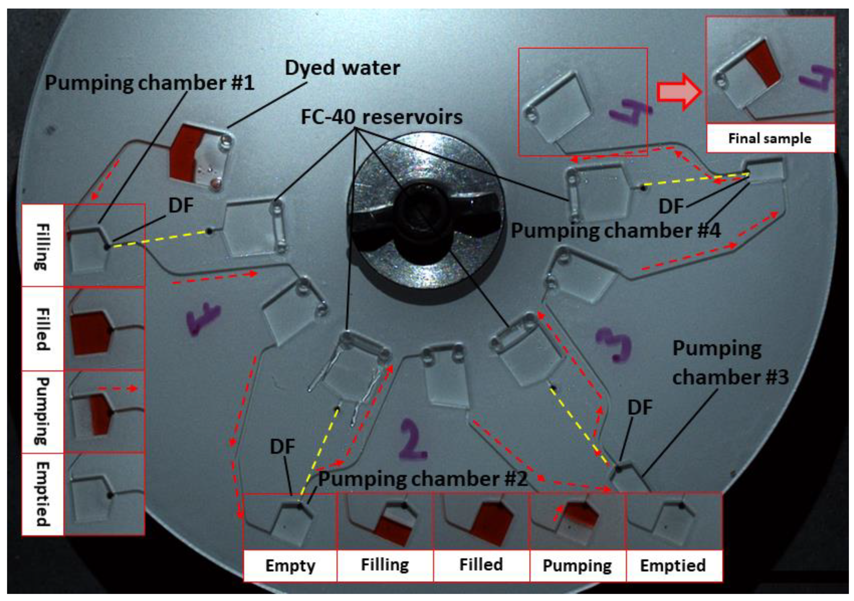
  • The sample volume Vaq should slightly exceed the volume of the pumping chamber. The sample will be metered by a pumping chamber and overflow will be returned to the sample reservoir. For example, in the reciprocal pumping design shown in Figure 4, a 90 µL volume is loaded and pumping chamber #1 is designed to be filled with 80 µL, and it is estimated that 80 µL is pumped to the next chamber (pumping chamber #2). In the case of the design shown in Figure 4, pumping chamber #2 and subsequent chambers, are sequentially smaller in size to ensure that they are filled by the sample prior to pumping.
  • Channel/reservoir volumes in the transfer zone (see Figure 2) should be as small as possible to minimise the volume of the pumping liquid required.
  • Before DF opening, the volume of pumping liquid VFC located radially inwards of r FC , C should slightly exceed the total dead volume of the reservoirs/channels located in the transfer and pumping zones. When pumping completes, the inner location of the pumping liquid should be at or radially inwards of r FC , C .
  • No air vents should be located in the transfer zone in order to prevent leakage of the sample or pumping liquid during operation.
  • The receiving reservoir radius, r aq , B , should be radially inwards of the pumping reservoir r FC , C . This prevents the pumping liquid from being displaced into the sample collection reservoir (which might cause issues with later downstream processing).
  • The length and cross-section of the connecting microchannels should be minimised as much as possible to reduce sample loss.
  • Variations in the microchannel parameters due to manufacturing tolerances should be taken into account in the designing phase.

3.2. Simulation of Manufacturing Tolerances

The mechanism of buoyancy-based centripetal pumping described in this paper can provide a mechanism for splitting and metering volumes of liquid [35]. For a LoaD to become a commercially viable prospect, the capability to mass-produce microfluidic discs must be demonstrated. In particular, the capability to inject mould discs [40] in an accurate and repeatable manner is key. Although the discs used in this study are manufactured using multi-layer methods as previously described [32], we analysed the impact that manufacturing tolerances have on a fluidic volume using Monte Carlo methods. As shown in Figure 3, dimensional variations, which are typical of high-precision injection moulding, resulted in a reduction in the volume of ~600 nL from an 80 μL chamber (~0.75%). Pumping liquid from smaller chambers manufactured with the same tolerances is expected to result in a larger percentage variation in the volume displaced. Furthermore, even larger variations in the volume pumped can be expected if using lower precision manufacturing such as the multi-layer method used in this paper.

3.3. Multi-Step Pumping

The basic principle described in Figure 1 can be applied to bidirectionally pump a single sample without any change in the disc spin rate. This multi-step pumping demonstrates the capability to reciprocate a liquid sample without impacting upstream or downstream LUOs, which might depend on a specific spin profile of the disc.
Figure 4 shows a structure that can pump a sample radially outwards and inwards four times. Here, the DF restraining the FC-40 is located at the top of the pumping chamber; pumping is only triggered when this chamber is filled. Additionally, this structure also allows accurate metering. Before the dissolution of the DFs, the aqueous sample reaches hydrostatic equilibrium (in a state similar to that in Figure 1a). Assuming the outlet, arm B, extends radially inwards of the loading chamber on arm A, once the structure is filled beyond its capacity, hydrostatic equilibrium is reached where the sample fully occupies the pumping chamber and partially fills the loading chamber and arm B to the same radial height. As the cross-sectional area of arm B is smaller than that of the reservoir (~0.05 mm2 vs. 15 mm2), any excess volume that is loaded will almost entirely be pumped back up arm A rather than being pumped forwards through arm B.
In the structure shown in Figure 4, when the sample enters the pumping chambers, the first DF dissolves. The sample is then displaced radially inwards by the inflow of FC-40. Informed by the analysis described in Section 3.2, the geometries of the pumping chambers are successively smaller than the volume pumped into them. This ensures that the DFs are wetted and the system accurately meters the liquid to the volumes defined by the chamber dimension. The remaining volume (overflow) pumped into each chamber is returned up the inlet arm, ensuring that the metered volume is dependent only on the volume of the metering chamber.

3.4. Recirculating Multi-Step Pumping

Figure 5 shows a more advanced version of the basic pumping structure. Here, when the DF is dissolved, the sample is displaced radially inwards on top of the FC-40 volume. Effectively, controlled recirculation is used to invert the system, whereby the lighter liquid is layered on top of the heavier liquid. As this happens, the FC-40 levels are reduced until the water-dissolvable film is exposed to the aqueous sample. The dissolving of this film allows the reagent to be directed into a peripheral sample collection chamber. This approach has several advantages. In the first case, the hydraulic pumping efficiency is enhanced as the aqueous sample layered on top of the FC-40 contributes to the buoyancy effect. Importantly, this concept allows significant space saving at the radially inward section of the disc, where real estate is at a premium. Thus, it might allow the automation of assays of greater complexities in smaller spaces by permitting the pumping of samples inwards multiple times from the edge of the disc.

3.5. Sample Aliquoting

As mentioned previously, DF-mediated buoyancy pumping can also allow a sample to be evenly and accurately split and metered and the excess sample will be returned through the loading channel. To demonstrate this capability, a combined aliquoting/metering/pumping structure is developed. This design is composed of four inverted pockets where three identical, defined pockets effectuate aliquoting and the fourth structure acts effectively as a waste or ‘overflow’ chamber.
In this approach (Figure 6), the sample is pumped into the metering structure and the DF is dissolved to initiate pumping. In the ideal case, the sample should fully occupy the metering structures before the DF dissolves (Figure 6c). As the FC-40 is released, the larger waste chamber is filled with the sample until the sample is discretised (Figure 6d). Here, the sample is pumped inwards and accurately aliquoted (Figure 6e,f).
The metering structure presented in Figure 6 (also Figure 7 and Figure 8) was characterised by the absorbance of dyed water using a method described previously [30]. Briefly, samples of dyed water were aliquoted, metered, and pumped to chambers on a disc, which were pre-loaded with a known volume of undyed water. At this point, the dyed water and non-dyed water mixed. The dye concentration in this mixture, measured via absorbance, was compared to a standard curve to estimate the initial volume of dyed water added to the chamber. The structures used in this study were found by this method to meter 24.4 μL ± 280 nL (n = 9); only a slight deviation from the nominal design value of 25 μL.
This structure can accurately aliquot and meter samples and then deliver them to distant locations on the disc. Rather than using a conventional metering structure, which often uses valves with significant dead volumes, the outlet from this structure is a microchannel of a minimal cross-section (0.5 × 0.086 mm2, as manufactured using the methods described here). If extended across the entire 120 mm diameter of a typical disc, this microchannel has a maximum dead volume of ~5 µL. Additionally, unlike conventional DF-valving technologies, metering using open microchannels is compatible with all non-aqueous liquids [41].

4. Liver Assay Panel

To exemplify how this pumping mechanism can be used for a multi-parameter bioassay, a liquid-handling protocol is developed to implement a three-parameter liver assay panel (Figure 7a). This structure is then tested using a calibrant (provided in the test kit) in lieu of a blood sample.
Three parameters are tested using the protocol and calibrant/reagents previously described [28]. Direct Bilirubin (DB, Reagent A) is an endpoint assay where the sample is added to the reagent and incubated. For Alkaline Phosphatase (ALP), the sample is added to the ALP reagent (Reagent B) and mixed for 3 min. After this reaction interval, the mixture is transferred to another chamber filled with ALP stop reagent (Reagent B’). Similarly, for Total Bilirubin (TB), the sample is added to the TB reagent (Reagent C) and incubated for 10 min before being transferred to another chamber to mix with the TB stop reagent (Reagent C’). As shown in the experiment’s spin protocol (Figure 7b), the sample is first centrifuged near the periphery of the disc, where the centrifugal field is strongest, to support fast blood separation. The mechanism of operation of the DF valves used has been previously described [29], whereas the particular architecture implemented in this paper is based on the work by Mishra et al. [42].
Subsequent reagent mixing is implemented using ‘shake mode’ [43], i.e., rapid cycles of disc acceleration and slowdown. The timed transfer of the stop reagents about the disc is governed by centrifugo-pneumatic DF valves, which are tuned to burst at 45 Hz (transfer Reagent B to Reagent B’) and 55 Hz (transfer Reagent C to Reagent C’). The operation of this disc is shown in Figure 8.
The results obtained using the calibrant sample are shown in Figure 9. The results acquired for ALP and TB show good agreement with the benchtop controls, whereas the results from the DB assay do not show good agreement. However, as the results from all three assays show good precision (i.e., minimal experiment-to-experiment variations), it can be surmised that this inaccuracy is a result of a systemic problem with the disc design, for example, unaccounted sample loss between the pumping structure and the Reagent A chamber. However, as the innovation focus of this work is on describing fully this buoyancy pumping and metering mechanism and from the good precision of this assay, it can be surmised that with a greater focus on assay optimisation and more reproducible manufacturing methods, the metering/pumping method could be used to reach a performance comparable to current ‘gold standard’ methods.

5. Conclusions and Outlook

In this work, we have presented a buoyancy-driven pumping technique controlled using dissolvable film valves driven by an (ancillary) immiscible liquid that centripetally displaces a lower-density aqueous liquid (sample). This new technology offers a number of advantages related to both the higher centrifugal field present in this area of the disc and the large available area at the edge of the disc. For example, blood processing, which takes place at the edge of the disc with plasma centripetally pumped inwards, will be much faster than if the blood is centrifuged near the centre of the disc. Furthermore, reagent reservoirs can be placed at the outer rim of the disc where a lot of space is available. For example, on a conventional CD-format disc with an outer diameter of 12 cm and an inner hole measuring 1.5 cm, more than 30% of its surface area is located within 10 mm of the outer edge. Conversely, less than 8.5% is contained within 10 mm of the inner edge around the central hole. Importantly, as shown in Figure 2, with a sufficient density difference between the pumping liquid and the sample, a reservoir of pumping liquid can be located in the ‘middle’ of the disc and generate sufficient buoyancy to displace a liquid to the more valuable inner locations of the disc.
The DFs dissolve upon contact with the (aqueous) sample so the initiation of centripetal pumping is ‘event triggered’; it is actuated by the movement of liquid into a reservoir. As the DFs can take up to 40 s to dissolve, the sample can enter the chamber fully before pumping is initiated. Any centrifugally pumped liquid flow on the Lab-on-a-Disc will only occur at a minimum disc spin rate, which is largely defined by parameters such as the geometry of the disc structures (e.g., microchannel cross-sections) and the contact angle between the liquid and the disc material [44], as well as the density of the liquids and the radial length and location of the fluid plugs. However, provided these interfacial effects are overcome by a minimum disc spin rate (found in this work to be approximately 15 Hz), the pumping method is largely independent of the spin rate so the method has a minimal impact on upstream and downstream LUOs, which might be dependent on a specific spin profile. As demonstrated, the method also has an inherent capability to accurately meter and aliquot samples during pumping from the disc periphery.
The combination of aqueous samples, water DFs, and non-aqueous dense pumping liquids can increase the number and nature of LUOs that can be integrated on the centrifugal platform, and thus offers an important step towards the development of highly automated and parallelised multi-parameter bioassay protocols.

Supplementary Materials

The following supporting information can be downloaded at: https://www.mdpi.com/article/10.3390/pr11010128/s1, Video S1: Single Pumping, Video S2: Multistep Pumping, Video S3: Recirculating Pumping, Video S4: Multistep Recirculating Pumping, Video S5: Liver Assay Panel Disc.

Author Contributions

Conceptualization, N.A.K., T.C.V., M.T.G., D.Z., C.B., J.D. and D.J.K. methodology, N.A.K., T.C.V. and D.J.K.; investigation and formal analysis, N.A.K., T.C.V., P.L.E., N.A.M., M.R., J.R., G.S.-M. and D.J.K.; resources, D.Z., C.B. and J.D.; writing—original draft preparation, N.A.K., T.C.V. and D.J.K.; writing—review and editing, N.A.K., T.C.V., P.L.E., N.A.M., M.R., J.R., G.S.-M., M.T.G., D.Z., C.B., J.D. and D.J.K.; supervision, D.Z., C.B., J.D. and D.J.K.; funding acquisition, C.B. and J.D. All authors have read and agreed to the published version of the manuscript.

Funding

This work was supported by Science Foundation Ireland under Grant No. 10/CE/B1821, Enterprise Ireland under Grant No. CF/2011/1317, the European Union under Grant No. FP7-KBBE-2013-7-613908-DECATHLON, and Science Foundation Ireland (SFI) and Fraunhofer-Gesellschaft under the SFI Strategic Partnership Programme Grant Number 16/SPP/3321.

Data Availability Statement

The data acquired to demonstrate centripetal pumping in this study is available in video form as Supplementary Material to this article at the links provided above.

Acknowledgments

The authors would like to acknowledge and thank Tríona M. O’Connell and Charles E. Nwankire for providing kind advice regarding the liver assay chemistry.

Conflicts of Interest

The authors declare no conflict of interest. The funders had no role in the design of the study; in the collection, analyses, or interpretation of data; in the writing of the manuscript; or in the decision to publish the results.

References

  1. Madou, M.; Zoval, J.; Jia, G.; Kido, H.; Kim, J.; Kim, N. Lab on a CD. Annu. Rev. Biomed. Eng. 2006, 8, 601–628. [Google Scholar] [CrossRef] [PubMed] [Green Version]
  2. Ducrée, J.; Haeberle, S.; Lutz, S.; Pausch, S.; Von Stetten, F.; Zengerle, R. The Centrifugal Microfluidic Bio-Disk Platform. J. Micromechanics Microengineering 2007, 17, S103. [Google Scholar] [CrossRef]
  3. Gorkin, R.; Park, J.; Siegrist, J.; Amasia, M.; Lee, B.S.; Park, J.-M.; Kim, J.; Kim, H.; Madou, M.; Cho, Y.-K. Centrifugal Microfluidics for Biomedical Applications. Lab A Chip 2010, 10, 1758–1773. [Google Scholar] [CrossRef] [PubMed] [Green Version]
  4. Strohmeier, O.; Keller, M.; Schwemmer, F.; Zehnle, S.; Mark, D.; von Stetten, F.; Zengerle, R.; Paust, N. Centrifugal Microfluidic Platforms: Advanced Unit Operations and Applications. Chem. Soc. Rev. 2015, 44, 6187–6229. [Google Scholar] [CrossRef] [Green Version]
  5. Chen, Q.; Cheung, K.; Kong, S.; Zhou, J.; Kwan, Y.; Wong, C.; Ho, H. An Integrated Lab-on-a-Disc for Automated Cell-Based Allergen Screening Bioassays. Talanta 2012, 97, 48–54. [Google Scholar] [CrossRef]
  6. Tang, M.; Wang, G.; Kong, S.-K.; Ho, H.-P. A Review of Biomedical Centrifugal Microfluidic Platforms. Micromachines 2016, 7, 26. [Google Scholar] [CrossRef] [Green Version]
  7. Smith, S.; Mager, D.; Perebikovsky, A.; Shamloo, E.; Kinahan, D.; Mishra, R.; Torres Delgado, S.M.; Kido, H.; Saha, S.; Ducrée, J. CD-Based Microfluidics for Primary Care in Extreme Point-of-Care Settings. Micromachines 2016, 7, 22. [Google Scholar] [CrossRef] [PubMed] [Green Version]
  8. Kong, M.C.; Salin, E.D. Spectrophotometric Determination of Aqueous Sulfide on a Pneumatically Enhanced Centrifugal Microfluidic Platform. Anal. Chem. 2012, 84, 10038–10043. [Google Scholar] [CrossRef]
  9. Hwang, H.; Kim, Y.; Cho, J.; Lee, J.; Choi, M.-S.; Cho, Y.-K. Lab-on-a-Disc for Simultaneous Determination of Nutrients in Water. Anal. Chem. 2013, 85, 2954–2960. [Google Scholar] [CrossRef]
  10. Czugala, M.; Maher, D.; Collins, F.; Burger, R.; Hopfgartner, F.; Yang, Y.; Zhaou, J.; Ducrée, J.; Smeaton, A.; Fraser, K.J. CMAS: Fully Integrated Portable Centrifugal Microfluidic Analysis System for on-Site Colorimetric Analysis. RSC Adv. 2013, 3, 15928–15938. [Google Scholar] [CrossRef]
  11. Nwankire, C.E.; Donohoe, G.G.; Zhang, X.; Siegrist, J.; Somers, M.; Kurzbuch, D.; Monaghan, R.; Kitsara, M.; Burger, R.; Hearty, S. At-Line Bioprocess Monitoring by Immunoassay with Rotationally Controlled Serial Siphoning and Integrated Supercritical Angle Fluorescence Optics. Anal. Chim. Acta 2013, 781, 54–62. [Google Scholar] [CrossRef]
  12. Glynn, M.; Kirby, D.; Chung, D.; Kinahan, D.J.; Kijanka, G.; Ducrée, J. Centrifugo-Magnetophoretic Purification of CD4+ Cells from Whole Blood toward Future HIV/AIDS Point-of-Care Applications. J. Lab. Autom. 2014, 19, 285–296. [Google Scholar] [CrossRef] [PubMed]
  13. Kinahan, D.J.; Kearney, S.M.; Kilcawley, N.A.; Early, P.L.; Glynn, M.T.; Ducree, J. Density-Gradient Mediated Band Extraction of Leukocytes from Whole Blood Using Centrifugo-Pneumatic Siphon Valving on Centrifugal Microfluidic Discs. PLoS ONE 2016, 11, e0155545. [Google Scholar] [CrossRef] [Green Version]
  14. Kinahan, D.J.; Kearney, S.M.; Glynn, M.T.; Ducrée, J. Spira Mirabilis Enhanced Whole Blood Processing in a Lab-on-a-Disk. Sens. Actuators A Phys. 2014, 215, 71–76. [Google Scholar] [CrossRef]
  15. Clime, L.; Brassard, D.; Geissler, M.; Veres, T. Active Pneumatic Control of Centrifugal Microfluidic Flows for Lab-on-a-Chip Applications. Lab A Chip 2015, 15, 2400–2411. [Google Scholar] [CrossRef] [PubMed]
  16. Abi-Samra, K.; Clime, L.; Kong, L.; Gorkin, R., III; Kim, T.-H.; Cho, Y.-K.; Madou, M. Thermo-Pneumatic Pumping in Centrifugal Microfluidic Platforms. Microfluid. Nanofluidics 2011, 11, 643–652. [Google Scholar] [CrossRef]
  17. Noroozi, Z.; Kido, H.; Madou, M.J. Electrolysis-Induced Pneumatic Pressure for Control of Liquids in a Centrifugal System. J. Electrochem. Soc. 2011, 158, P130. [Google Scholar] [CrossRef]
  18. Garcia-Cordero, J.L.; Basabe-Desmonts, L.; Ducrée, J.; Ricco, A.J. Liquid Recirculation in Microfluidic Channels by the Interplay of Capillary and Centrifugal Forces. Microfluid. Nanofluidics 2010, 9, 695–703. [Google Scholar] [CrossRef] [Green Version]
  19. Godino, N.; Gorkin, R., III; Linares, A.V.; Burger, R.; Ducrée, J. Comprehensive Integration of Homogeneous Bioassays via Centrifugo-Pneumatic Cascading. Lab A Chip 2013, 13, 685–694. [Google Scholar] [CrossRef]
  20. Zehnle, S.; Schwemmer, F.; Roth, G.; von Stetten, F.; Zengerle, R.; Paust, N. Centrifugo-Dynamic Inward Pumping of Liquids on a Centrifugal Microfluidic Platform. Lab A Chip 2012, 12, 5142–5145. [Google Scholar] [CrossRef]
  21. Schwemmer, F.; Zehnle, S.; Mark, D.; von Stetten, F.; Zengerle, R.; Paust, N. A Microfluidic Timer for Timed Valving and Pumping in Centrifugal Microfluidics. Lab A Chip 2015, 15, 1545–1553. [Google Scholar] [CrossRef] [Green Version]
  22. Gorkin, R., III; Clime, L.; Madou, M.; Kido, H. Pneumatic Pumping in Centrifugal Microfluidic Platforms. Microfluid. Nanofluidics 2010, 9, 541–549. [Google Scholar] [CrossRef] [Green Version]
  23. Schwemmer, F.; Hutzenlaub, T.; Buselmeier, D.; Paust, N.; von Stetten, F.; Mark, D.; Zengerle, R.; Kosse, D. Centrifugo-Pneumatic Multi-Liquid Aliquoting—Parallel Aliquoting and Combination of Multiple Liquids in Centrifugal Microfluidics. Lab A Chip 2015, 15, 3250–3258. [Google Scholar] [CrossRef] [Green Version]
  24. Kinahan, D.J.; Burger, R.; Lawlor, D.; Early, P.L.; Vembadi, A.; McArdle, N.A.; Kilcawley, N.A.; Glynn, M.T.; Ducrée, J. Centrifugally Automated Solid-Phase Extraction of DNA by Immiscible Liquid Valving and Chemically Powered Centripetal Pumping of Peripherally Stored Reagents. Biosens. Bioelectron. X 2021, 9, 100085. [Google Scholar] [CrossRef]
  25. Dignan, L.M.; Karas, S.M.; Mighell, I.K.; Treene, W.R.; Landers, J.P.; Woolf, M.S. A Novel Method for Inward Fluid Displacement in Centrifugal Microdevices for Highly Integrated Nucleic Acid Processing with Long-Term Reagent Storage. Anal. Chim. Acta 2022, 1221, 340063. [Google Scholar] [CrossRef]
  26. Krauss, S.T.; Woolf, M.S.; Hadley, K.C.; Collins, N.M.; Nauman, A.Q.; Landers, J.P. Centrifugal Microfluidic Devices Using Low-Volume Reagent Storage and Inward Fluid Displacement for Presumptive Drug Detection. Sens. Actuators B Chem. 2019, 284, 704–710. [Google Scholar] [CrossRef]
  27. Kong, M.C.; Bouchard, A.P.; Salin, E.D. Displacement Pumping of Liquids Radially Inward on Centrifugal Microfluidic Platforms in Motion. Micromachines 2011, 3, 1–9. [Google Scholar] [CrossRef] [Green Version]
  28. Soroori, S.; Kulinsky, L.; Kido, H.; Madou, M. Design and Implementation of Fluidic Micro-Pulleys for Flow Control on Centrifugal Microfluidic Platforms. Microfluid. Nanofluidics 2014, 16, 1117–1129. [Google Scholar] [CrossRef] [Green Version]
  29. Gorkin, R., III; Nwankire, C.E.; Gaughran, J.; Zhang, X.; Donohoe, G.G.; Rook, M.; O’Kennedy, R.; Ducrée, J. Centrifugo-Pneumatic Valving Utilizing Dissolvable Films. Lab A Chip 2012, 12, 2894–2902. [Google Scholar] [CrossRef] [PubMed]
  30. Nwankire, C.E.; Chan, D.-S.S.; Gaughran, J.; Burger, R.; Gorkin, R., III; Ducrée, J. Fluidic Automation of Nitrate and Nitrite Bioassays in Whole Blood by Dissolvable-Film Based Centrifugo-Pneumatic Actuation. Sensors 2013, 13, 11336–11349. [Google Scholar] [CrossRef]
  31. Nwankire, C.E.; Czugala, M.; Burger, R.; Fraser, K.J.; Glennon, T.; Onwuliri, B.E.; Nduaguibe, I.E.; Diamond, D.; Ducrée, J. A Portable Centrifugal Analyser for Liver Function Screening. Biosens. Bioelectron. 2014, 56, 352–358. [Google Scholar] [CrossRef] [Green Version]
  32. Kinahan, D.J.; Kearney, S.M.; Dimov, N.; Glynn, M.T.; Ducrée, J. Event-Triggered Logical Flow Control for Comprehensive Process Integration of Multi-Step Assays on Centrifugal Microfluidic Platforms. Lab A Chip 2014, 14, 2249–2258. [Google Scholar] [CrossRef] [Green Version]
  33. Kinahan, D.J.; Kearney, S.M.; Faneuil, O.P.; Glynn, M.T.; Dimov, N.; Ducrée, J. Paper Imbibition for Timing of Multi-Step Liquid Handling Protocols on Event-Triggered Centrifugal Microfluidic Lab-on-a-Disc Platforms. RSC Adv. 2015, 5, 1818–1826. [Google Scholar] [CrossRef] [Green Version]
  34. Kinahan, D.J.; Early, P.L.; Vembadi, A.; MacNamara, E.; Kilcawley, N.A.; Glennon, T.; Diamond, D.; Brabazon, D.; Ducrée, J. Xurography Actuated Valving for Centrifugal Flow Control. Lab A Chip 2016, 16, 3454–3459. [Google Scholar] [CrossRef]
  35. Miyazaki, C.M.; Kinahan, D.J.; Mishra, R.; Mangwanya, F.; Kilcawley, N.; Ferreira, M.; Ducrée, J. Label-Free, Spatially Multiplexed SPR Detection of Immunoassays on a Highly Integrated Centrifugal Lab-on-a-Disc Platform. Biosens. Bioelectron. 2018, 119, 86–93. [Google Scholar] [CrossRef]
  36. Bartholomeusz, D.A.; Boutté, R.W.; Andrade, J.D. Xurography: Rapid Prototyping of Microstructures Using a Cutting Plotter. J. Microelectromechanical Syst. 2005, 14, 1364–1374. [Google Scholar] [CrossRef]
  37. Grumann, M.; Brenner, T.; Beer, C.; Zengerle, R.; Ducrée, J. Visualization of Flow Patterning in High-Speed Centrifugal Microfluidics. Rev. Sci. Instrum. 2005, 76, 025101. [Google Scholar] [CrossRef] [Green Version]
  38. Brennan, D.; Coughlan, H.; Clancy, E.; Dimov, N.; Barry, T.; Kinahan, D.; Ducrée, J.; Smith, T.J.; Galvin, P. Development of an On-Disc Isothermal In Vitro Amplification and Detection of Bacterial RNA. Sens. Actuators B Chem. 2017, 239, 235–242. [Google Scholar] [CrossRef] [Green Version]
  39. Delgado, S.M.T.; Kinahan, D.J.; Julius, L.A.N.; Mallette, A.; Ardila, D.S.; Mishra, R.; Miyazaki, C.M.; Korvink, J.G.; Ducrée, J.; Mager, D. Wirelessly Powered and Remotely Controlled Valve-Array for Highly Multiplexed Analytical Assay Automation on a Centrifugal Microfluidic Platform. Biosens. Bioelectron. 2018, 109, 214–223. [Google Scholar] [CrossRef] [PubMed] [Green Version]
  40. Morelli, L.; Serioli, L.; Centorbi, F.A.; Jendresen, C.B.; Matteucci, M.; Ilchenko, O.; Demarchi, D.; Nielsen, A.T.; Zór, K.; Boisen, A. Injection Molded Lab-on-a-Disc Platform for Screening of Genetically Modified, E. Coli Using Liquid-Liquid Extraction and Surface Enhanced Raman Scattering. Lab A Chip 2018, 18, 869–877. [Google Scholar] [CrossRef]
  41. Mishra, R.; Alam, R.; McAuley, D.; Bharaj, T.; Chung, D.; Kinahan, D.J.; Nwankire, C.; Anderson, K.S.; Ducrée, J. Solvent Selective Membrane Routing and Microfluidic Architecture towards Centrifugal Automation of Customisable Bead Based Immunoassays. Sens. Actuators B Chem. 2022, 356, 131305. [Google Scholar] [CrossRef]
  42. Mishra, R.; Zapatero-Rodriguez, J.; Sharma, S.; Kelly, D.; McAuley, D.; Gilgunn, S.; O’Kennedy, R.; Ducree, J. Automation of Multi-Analyte Prostate Cancer Biomarker Immunoassay Panel from Whole Blood by Minimum-Instrumentation Rotational Flow Control. Sens. Actuators B Chem. 2018, 263, 668–675. [Google Scholar] [CrossRef]
  43. Grumann, M.; Geipel, A.; Riegger, L.; Zengerle, R.; Ducrée, J. Batch-Mode Mixing on Centrifugal Microfluidic Platforms. Lab A Chip 2005, 5, 560–565. [Google Scholar] [CrossRef] [PubMed]
  44. Chen, J.M.; Huang, P.-C.; Lin, M.-G. Analysis and Experiment of Capillary Valves for Microfluidics on a Rotating Disk. Microfluid. Nanofluidics 2008, 4, 427–437. [Google Scholar] [CrossRef]
Figure 1. Basic pumping concept. (a) Disc loaded at a lower spin rate. The FC-40 (red) is restrained by a DF table. The aqueous sample (yellow) is stopped by a capillary valve. (b) Upon elevation of the spin rate beyond its burst frequency, the sample is transferred into the pumping chamber through arm A. The DF is wetted and opened. (c) The high-density FC-40 is centrifugally pumped (arm C) to flow underneath and then lift the aqueous layer. The sample is then displaced radially inwards (arm B) into the collection chamber. (d) Pumping is completed when the system reaches hydrostatic equilibrium.
Processes 11 00128 g001
Figure 2. Effect of the location of the pumping reservoir and the density of the pumping liquid on the radial distance to which the sample can be pumped. Here, it is assumed that the sample is pumped from a chamber at or radially outward of 50 mm (Raq,B). (a) Basic pumping structure displaying reservoirs for the high-density pumping liquid and sample. Arm A, arm B, and arm C correspond to the inlet arm, outlet arm, and pumping liquid arm, as defined in Figure 1. (b) The location of the outlet of the reservoir (rFC,C) is on the minimum radial location of the inlet to the receiving reservoir (raq,B), where a sample must be pumped centripetally from a radius of 50 mm. Here, should the pumping reservoir outlet be located at rFC,C = 40 mm, it might be expected that the sample can be pumped centripetally to raq,B = 29 mm should the pumping liquid be FC-40, but only to 38 mm if the pumping liquid is typical heavy oil (SG 1.1). Should the outlet of the pumping reservoir (rFC,C) be located radially inwards of 33 mm, FC-40 can displace the aqueous sample to the centre of the rotation.
Processes 11 00128 g002
Figure 3. Monte Carlo simulation (99,999 runs) for the distribution of (aqueous) sample from a chamber in an injection-moulded part. The chamber has a nominal volume of 80 μL (dimensions 12.5 mm long, 8 mm wide, and 1 mm deep) and the model assumes manufacturing of an 8 μm systematic thermal shrinkage and a 2 µm tolerance in thickness.
Processes 11 00128 g003
Figure 4. Multi-step reciprocating pumping is demonstrated using coloured water and FC-40. The organic-based FC-40 is prevented from entering the pumping chamber from the underside by the water-specific DFs. Hidden connecting channels are illustrated by dashed yellow lines. The sample is loaded and the disc is rotated at 30 Hz. Pumping chamber #1 fills with dyed water and wets the DF from the topside. Due to its higher density, the released FC-40 flows underneath the coloured water, which is then displaced radially inwards. This sample is then pumped radially outwards to the next pumping chamber. This buoyancy-driven reciprocation of flow is repeated four times. Note that the volume of the pumping chambers decreases due to losses. However, this volume reduction also accurately meters the samples pumped from each chamber (see Videos S1 and S2 in ESI).
Processes 11 00128 g004
Figure 5. Recirculating pumping. (a) Disc cartridge in the initial configuration. At the start, non-aqueous FC-40 is restrained by the lower DF from entering the pumping chamber and by the upper DF from entering the collection chamber. The sample is restrained behind a DF burst valve. Connecting channels on the underside of the disc are shown with dashed yellow lines. (b) The spin rate is increased and centrifugally drives the sample into the pumping chamber. (c) The lower DF is wetted to pneumatically release the FC-40. (d,e) The recirculating flow is powered by the centripetal displacement of the sample containing the higher-density FC-40. This process continues until hydrostatic equilibrium is reached. (f) The upper DF is wetted by the (aqueous) sample and dissolves. (g,h) The sample is released to the collection chamber representing further LUOs. Note that in the experiment above, the volumes of FC-40 were tailored to minimise both the amount of FC-40 passed to the collection chamber and the volume of sample lost during pumping. Proper reduction of this FC-40 volume permits metering of the sample in the upper chamber (see also Videos S3 and S4 in the ESI).
Processes 11 00128 g005
Figure 6. Schematic of metering function. Here, the sample is aliquoted into three identical volumes. (a) Metering structure. (b) The sample (yellow) enters the system and wets the DF. (c) The sample fills the structure. Within the 40 s dissolution time of the DF, the filling of the metering structure completes. (d) FC-40 (red) is released and centripetally displaces the lighter sample. The sample aliquots are isolated once their outer end has fully risen into the V-shaped metering structures. (e,f) The system seeks hydrostatic equilibrium by centripetal pumping of the aliquoted and metered samples.
Processes 11 00128 g006
Figure 7. (a) Schematic of multi-parameter disc with the optimised spatial distribution of chambers. Note that the crossing channels are enabled by the multilayer architecture. (b) The operational spin protocols. The spin rates used are defined in the article text.
Processes 11 00128 g007
Figure 8. Disc designed for integrated bio-assays using integrated metering/mixing/pumping. (a) The disc is pre-loaded with FC-40 as the pumping liquid, clear (DI) water and dyed water to represent the bio-reagents, and working sample (blood/plasma), respectively. Connecting channels on the underside of the disc are shown by dashed yellow lines. (b) Increasing the spin rate to 30 Hz (Figure 7b) releases dyed water into the metering structure. (c) The DF located in the metering structure opens to release the FC-40. The sample is aliquoted, accurately metered, and pumped radially inwards. (d) The sample is added to Reagents A, B, and C and mixed using the rotational ‘shake mode’-induced Euler force. (e) After 3 min, the spin rate is increased to 45 Hz and plasma/Reagent B solution is released into the read chamber where it mixes with the ‘stop reagent’ Reagent B’. (f) Similarly, after a further 12 min, the spin rate is increased to 55 Hz and the plasma/Reagent C solution is mixed with Reagent C’. Note that the disc shown in this figure has an identical function but a slightly different architecture (location of waste collection chamber; size of read chambers) compared to the disc shown in Video S5 (the disc in Video S5 was used to generate the results described in Section 4).
Processes 11 00128 g008
Figure 9. Comparison of benchtop results (n = 5) vs. sample processed on disc (n = 3). The 0% calibrant (i.e., for baseline subtraction) was DI water. The 100% calibrants are 21.2 µmol L−1 DB, 127 U L−1 ALP, and 29.2 μmol L−1, respectively.
Processes 11 00128 g009
Disclaimer/Publisher’s Note: The statements, opinions and data contained in all publications are solely those of the individual author(s) and contributor(s) and not of MDPI and/or the editor(s). MDPI and/or the editor(s) disclaim responsibility for any injury to people or property resulting from any ideas, methods, instructions or products referred to in the content.

