Article

Study on Optimization of Initial Support for a Tunnel in the Fracture Zone Based on the Strength Reduction Method

State Key Laboratory for Geomechanics and Deep Underground Engineering, China University of Mining and Technology, Xuzhou 221116, China
*
Author to whom correspondence should be addressed.
Processes 2022, 10(8), 1558; https://doi.org/10.3390/pr10081558
Submission received: 5 July 2022 / Revised: 3 August 2022 / Accepted: 3 August 2022 / Published: 9 August 2022
(This article belongs to the Special Issue Advanced Processes Creating New Technologies in Tomorrow's Industry)

Abstract

:
In this paper, the fracture zone of the Chunxuan Road Tunnel in Jinan, Shandong Province, China was selected for the engineering background. With reference to the field monitoring data, a finite element model was established based on the strength reduction method. With the aid of this model, the influences of different initial support parameters (including lining, bolt and steel arch) on the tunnel deformation in the fracture zone were analyzed to obtain reasonable initial support parameters. The results show that the tunnel deformation under the original initial support is severe. Among the initial support methods, such as lining, bolt, and steel arch, the parameters of the lining and steel arch significantly influence the tunnel deformation in the fracture zone. Therefore, selecting appropriate initial support parameters can effectively control the tunnel deformation in the fracture zone. After the optimized support scheme is adopted, failure instability no longer occurs in the tunnel and the tunnel deformation is also effectively controlled. The research findings provide a clear reference for deformation control and support scheme optimization of similar projects.

1. Introduction

In recent years, there has been a rapid development of China’s transportation system, and remarkable breakthroughs have been made in railway tunnel construction. To date, over 17,000 tunnels have been put into operation [1]. Tunnel construction that crosses geologically unfavorable regions has become quite common. When crossing the fracture zone, tunnels are likely to deform seriously, due to poor lithology of their surrounding rock. The resultant problems, such as arch distortion, lining fracturing, and exceeding the clearance limit, bring significant potential safety hazards to the tunnel support structure and normal construction and so have come a focus in the engineering industry [2].
At present, research methods of tunnel deformation control and support optimization mainly include theoretical analysis, on-site test monitoring, and numerical simulation. Tomanovic et al. [3] researched the deformation characteristics and support measures of surrounding rock in the shallow-buried section at the entrance of the soft-rock tunnel through numerical simulation and on-site monitoring. Based on the research results, they put forward measures for controlling deformation in the Dafalang Tunnel. Guo et al. [4,5] monitored four experimental support schemes for serious deformation of surrounding rock on the construction site. By comparing the support effects of those schemes according to the monitoring results, they proposed a reasonable support scheme to solve the serious deformation of the Zhongyi Tunnel. Through on-site tunnel deformation monitoring and numerical simulation analysis, Chen et al. [6] and Wu et al. [7] explored the deformation and support stress of the tunnel under different support parameters and adjusted the original support parameters of the tunnel. By taking loess tunnels with large cross sections in the Zhengzhou–Xi’an Passenger Dedicated Line as the engineering background, Mu et al. [8] and Chen et al. [9] concluded that the arch system anchor bolts had a limited effect on deep-buried and shallow-buried loess tunnels, based on on-site test analysis, and removing the arch system anchor bolts could accelerate the section closure, control the subsidence and deformation, and save the project investment. By conducting on-site tests in the Baojiashan Highway Tunnel, Sun et al. [10] found that the steel frame played a notable supporting role in the tunnel with soft surrounding rock; removing the system anchor bolt did not affect the stability of the initial supporting structure. Instead, it not only shortened the procedure cycle time, but also saved project costs. Wu et al. [11] systematically explored the action mechanism and the on-site support effect of the section steel frame support structure and the grid steel frame support structure by means of laboratory test, numerical simulation, theoretical analysis, and on-site test, which provided the basis for the design and construction of initial support in the future. According to the results of numerical simulation and on-site monitoring in the Youfangping Tunnel of Guzhu Expressway, Chen et al. [12] believed that weakening bolts and enhancing the stiffness and strength of the initial support could effectively control the serious deformation in the soft-rock tunnel, which provides a reference for support in similar tunnels. Although many studies have been conducted on tunnel deformation control and support optimization, research into the mechanical response, design parameters, and construction methods of the support structure during construction remain limited. As the Chunxuan Road Tunnel in Ji’nan City crosses the fracture zone where the lithology of the surrounding rock is relatively poor, numerous support optimization methods and supporting approaches are not fully applicable to its deformation control [13,14,15,16,17,18,19,20,21].
In this study, with the Chunxuan Road Tunnel in the fracture zone in the Ji’nan Province taken as an example, in view of the characteristics of rock fragmentation and joint fissure development in the contact fracture zone between limestone and diorite in Chunxuan road tunnel, the strength reserve of surrounding rock was calculated by the strength reduction method. On this basis, the control effects of different support parameters on tunnel deformation were systematically investigated. Furthermore, the design of the initial support was optimized. Finally, the rationality of the support optimization scheme was verified with reference to on-site monitoring data. The research results provide a reference for the support optimization of this tunnel and similar projects in the future.

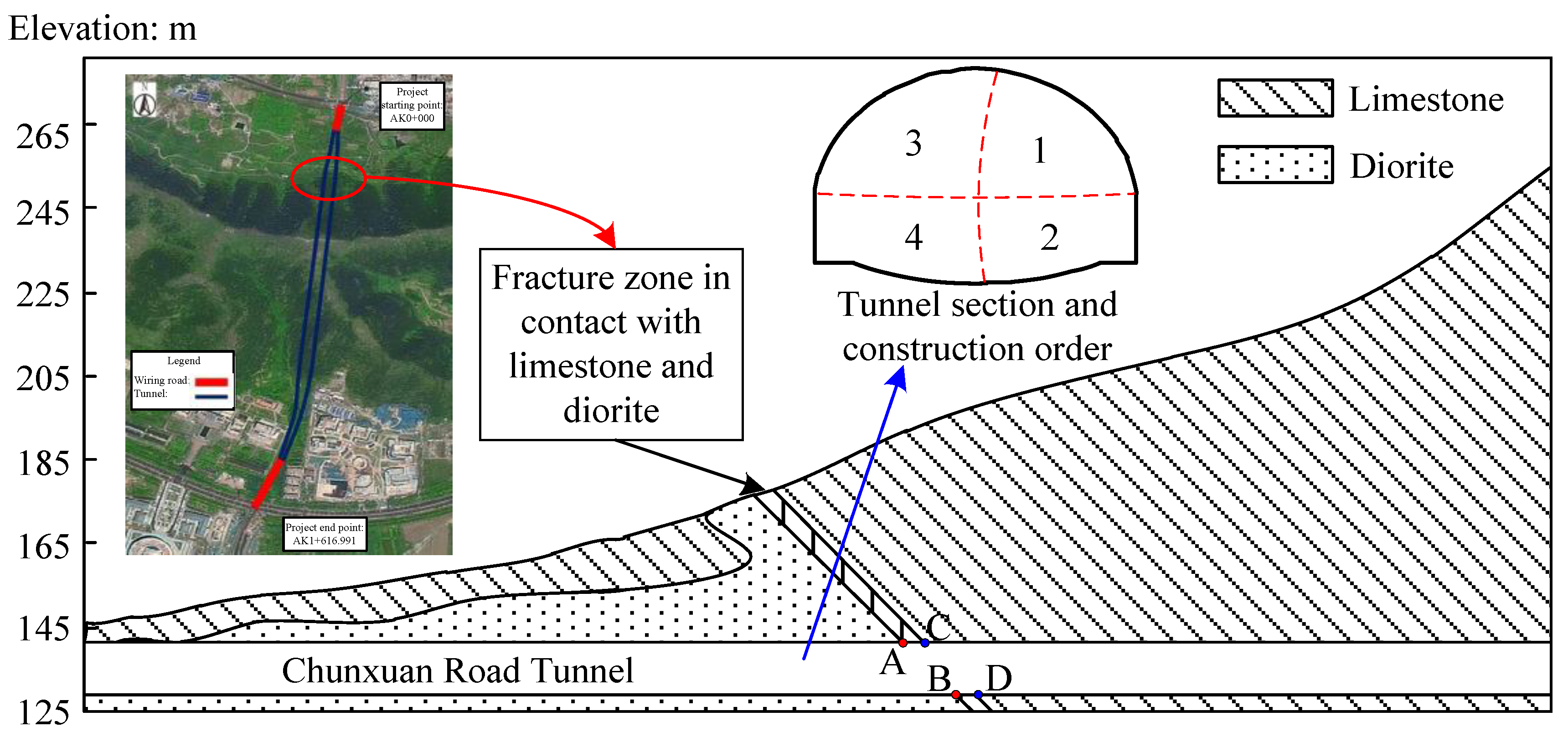
2. Analysis of the Deformation of the Chunxuan Road Tunnel in the Fracture Zone

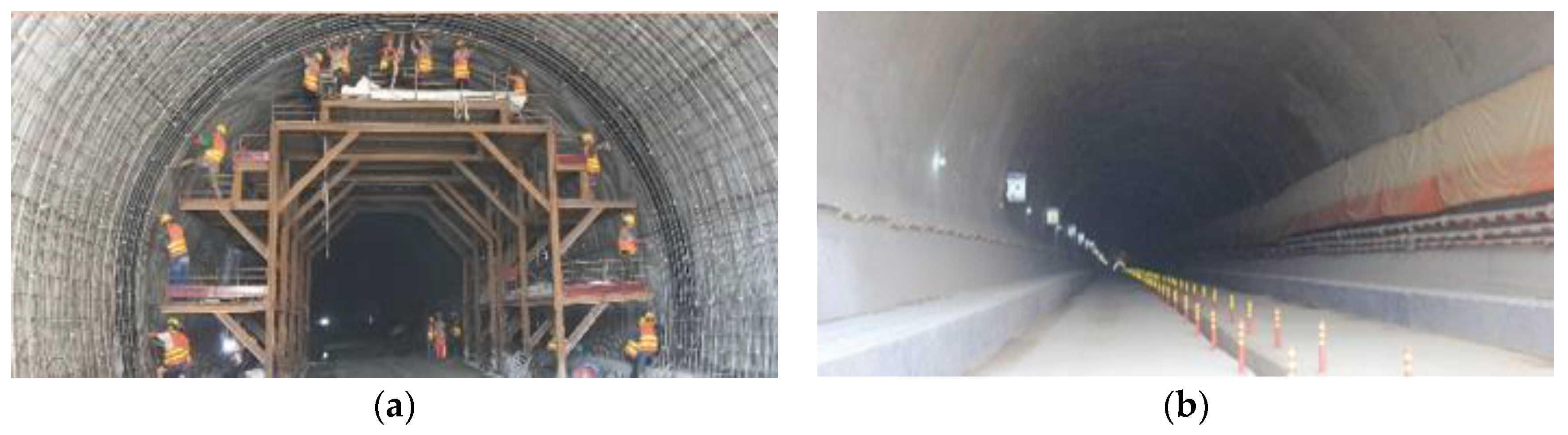
2.1. Project Profile

This study is based on the Chunxuan Road (Chunxiu Road–East Jingshi Road) Tunnel in Ji’nan, Shandong Province, China. This tunnel is located near the junction of Caishi Street and Suncun Street in the Licheng District, Ji’nan Province. It starts from the intersection of the current Chunxuan Road and Chunxiu Road in the north, and ends at the intersection of the Chunxuan Road under construction and East Jingshi Road in the south. Yuhuang Mountain is the main construction area at present. The cuttings on the north and south sides are located at the foot of the Yuhuang Mountain. The tunnel has a total length of 1150 m and it is a double-hole and double-line tunnel. Limestone and diorite exposed during tunnel construction are in contact with the fracture zone where the rock mass is rather broken and the joints and fractures are developed. The thickness of the limestone/diorite layer above the fracture zone is 50 m. The geological condition of the tunnel in the fracture zone is shown in Figure 1. The tunnel is constructed by the CD double-step method, and the support parameters of surrounding rock design are given in Table 1.
Deformation intensified suddenly when tunnel construction entered the fracture zone that is in contact with the limestone and diorite, which is manifested by lining fracturing, the initial support exceeding the clearance limit and arch distortion. Continuous monitoring of this section reveals that the maximum vertical displacement of the tunnel has reached 267 mm. To control the large vertical deformation of the tunnel, the departments involved in the construction adjusted the support scheme in good time. Subsequently, the horizontal convergence of the tunnel decreased to 195 mm, but it still exceeded the monitoring and early warning value. Therefore, the on-site tunnel face was temporarily closed, and reinforcement measures, such as a temporary inverted arch, were adopted to continuously monitor and test this section.

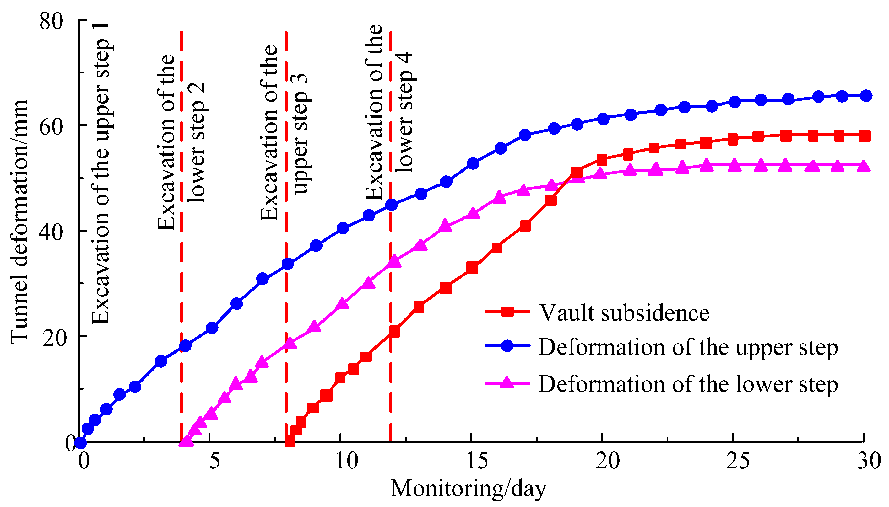
2.2. On-Site Deformation Analysis

To further analyze the causes of tunnel deformation and optimize the original support parameters, the surrounding rock deformation of the tunnel in the fracture zone was monitored. The layout of measuring points is shown in Figure 2, where A–E are the monitoring points of surrounding rock deformation.
Based on Figure 2, the surrounding rock deformation of the monitored section was examined according to the monitoring procedure, and the monitoring results are displayed in Figure 3. It can be seen from Figure 3 that the maximum subsidence value of the vault is 151.7 mm; the maximum subsidence rate is approximately 13.6 mm/d. The maximum horizontal convergence of the upper step is 187.9 mm; the maximum horizontal convergence rate is around 20.5 mm/d. The maximum horizontal convergence of the lower step is 128.4 mm; the maximum horizontal convergence rate is approximately 11.5 mm/d. On the 17th day, the inverted arch is constructed, marking the completion of tunnel support. On the 23rd day, the surrounding rock deformation converges and gradually stabilizes. The analysis reveals that the upper step corresponds to a clearly larger deformation value than the lower step. The reason is as follows: the inverted arch construction is completed soon after the excavation of the lower step, and thus the support structure becomes integrated, which enhances the ability to restrain the deformation of the tunnel surrounding rock; consequently, the surrounding rock deformation of the lower step converges much more easily. This indicates that early completion of the support structure can lead to early convergence of the surrounding rock deformation. The monitoring results suggest serious tunnel deformation, and the high deformation rate of the tunnel poses considerable pressure to the support structure, so that the tunnel is prone to failure and instability.

3. Analysis of Tunnel Support Optimization Based on the Strength Reduction Method

3.1. Numerical Simulation Application of the Strength Reduction Method

According to Specification for Design of Highway Tunnels (JTG 3370.1-2018), the initial uniaxial compressive strength of rock σ0 is correlated with the ultimate uniaxial compressive strength σ1:
σ 1 = 1 K σ 0
  • where σ0 is the initial uniaxial compressive strength, MPa;
  • σ1 is the ultimate uniaxial compressive strength, MPa;
  • K is the strength reduction coefficient.
The strength reduction coefficient K is determined by the development degree of joints and fractures of macro rock mass. The strength reduction method is introduced into the FLAC3D numerical simulation analysis to reduce the strength of surrounding rock materials and to optimize the initial support parameters of the tunnel. The reduced strength of surrounding rock is expressed as [22,23]:
{ c 1 = 1 K c 0 tan φ 1 = 1 K tan φ 0
  • where c0 is the initial cohesion, MPa;
  • c1 is the ultimate cohesion, MPa;
  • φ0 is the initial internal friction angle, °;
  • φ1 is the ultimate internal friction angle, °.

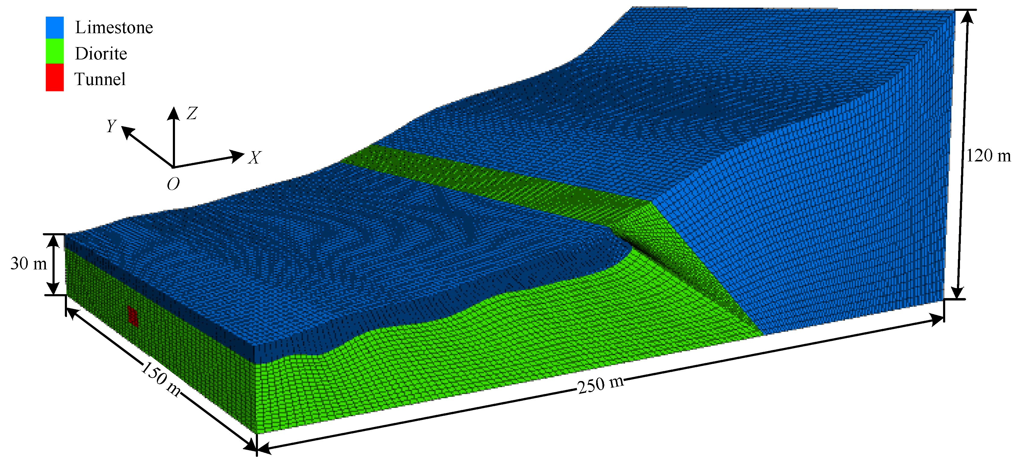
3.2. The Model for Numerical Calculation

According to the engineering geological condition of the Chunxuan Road Tunnel, a 250 m × 150 m × 30~120 m finite element model was established. The model includes self-weight. The grid division of tunnel is shown in Figure 4.
The tunnel was excavated by the CD double-step method, and the surrounding rock follows the Mohr Coulomb yield criterion. The lining adopted the shell element and the steel arch frame adopted the beam element. In this paper, the mechanical parameters of the surrounding rock supporting the project are measured by the conventional triaxial test of rock, so as to obtain accurate and reliable mechanical parameters of the surrounding rock for numerical calculation research. The model material parameters are listed shown in Table 2.

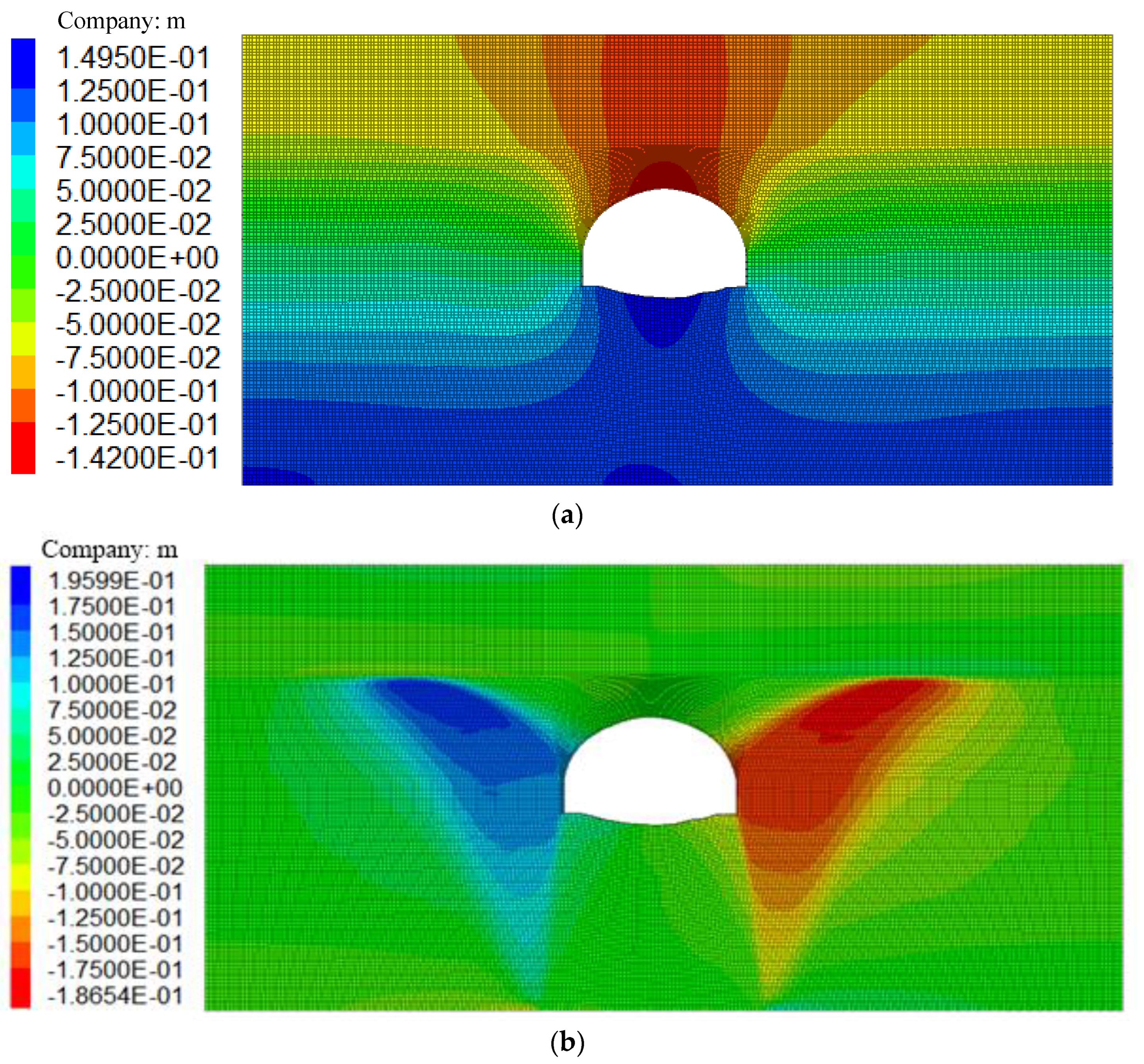
3.3. Simulation Analysis of the Original Initial Support Scheme

The original initial support condition of the tunnel was modeled and calculated, and the results are illustrated in Figure 5. After the completion of the support for tunnel excavation, the vertical displacement at the vault is 142.7 mm, and the maximum horizontal deformation occurs at the side wall of the upper step, with a deformation value of 186.5 mm.
The numerical simulation results of the original initial support scheme were contrasted with the on-site measured data (Figure 6). It can be seen from Figure 6 that the numerical simulation results vary in a similar trend to the actual on-site measured data overall, but their tunnel deformations differ slightly. The deviation is attributable to the complex and changeable actual geological conditions, as well as the on-site measurement errors. Nevertheless, the on-site measurement errors are all ±15 mm, considering that the deviation is limited, and that the simulation results and the measured data share overall similar variations, the established model can be used for the analysis of tunnel support optimization.

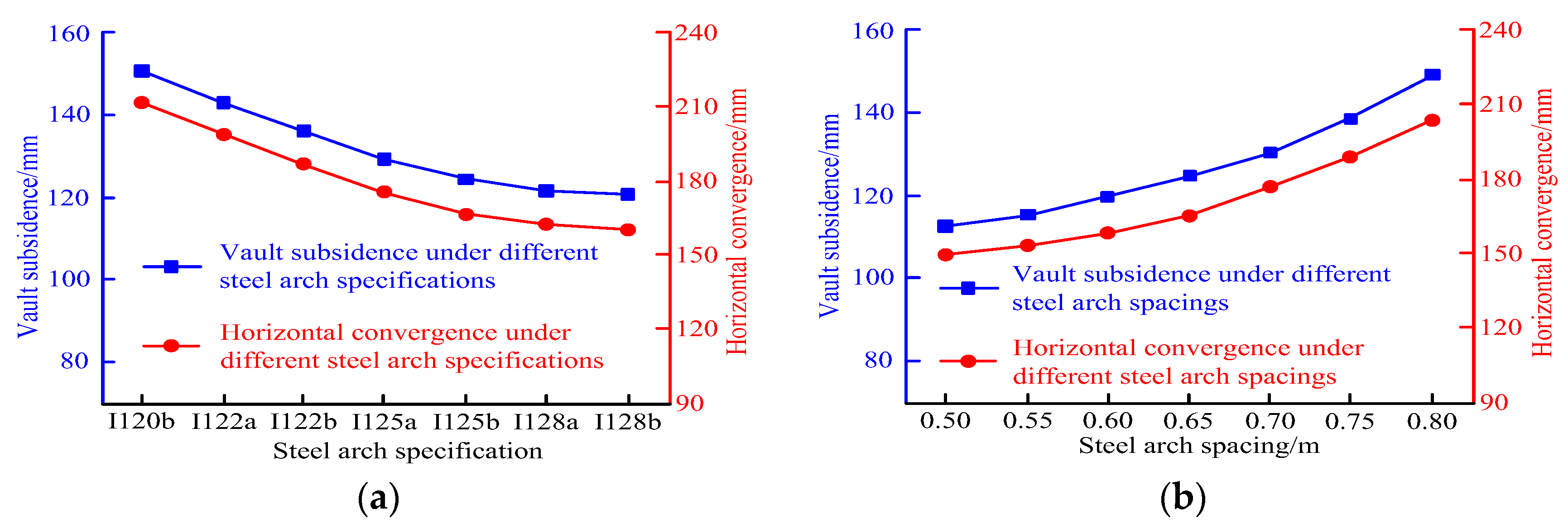
3.4. Analysis of Steel Arch Frame Parameter Optimization

A steel arch frame, one of the commonly used support structure measures in railway and highway tunnels, can influence the deformation of the tunnel’s surrounding rock to different extents [24,25]. The difference is mainly reflected in the support stiffness and arch frame spacing, and the corresponding parameters of the steel arch frame are steel arch frame specification and spacing. Seven commonly used steel arch frame models with different specifications, namely I20b, I22a, I22b, I25a, I25b, I28a, and I28b, were selected. Seven different steel arch frame spacings, i.e., 0.50 m, 0.55 m, 0.60 m, 0.65 m, 0.70 m, 0.75 m, and 0.80 m, were selected. On the basis of the existing support condition, the steel arch frame parameters were optimized by simulating the layout of steel arch frames with different specifications and spacings, respectively. The simulation results are shown in Figure 7.
According to Figure 7, for I20b, the tunnel vault subsidence is 152.1 m and the maximum horizontal displacement is 211.7 m. For I22b, the above two values are 139.6 m and 178.5 m, respectively. For I28a, they decline to 122.5 m and 163.1 m, respectively. When the steel arch spacing is 0.5 m, the two values are 114.7 m and 151.3 m, respectively. When the spacing is 0.8 m, the two values rise to 149.8 m and 204.5 m, respectively. On the whole, the tunnel deformation decreases with the increase in steel arch specification at a falling rate; yet it increases with the rise of steel arch spacing at a rising rate. In the optimization of steel arch frame parameters, considering the actual tunnel situation, the specification of steel arch frame should be no lower than I28a, and the spacing should be no less than 0.55 m to meet the requirements of tunnel support.

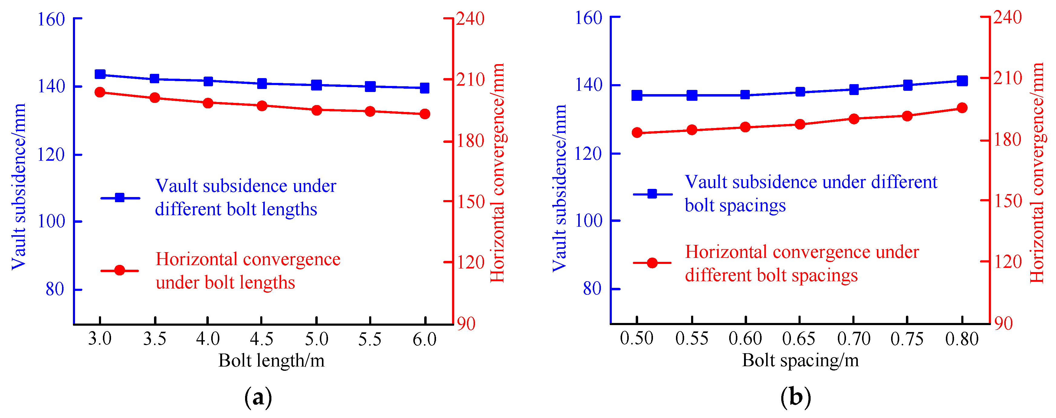
3.5. Analysis of Bolt Parameter Optimization

Bolt length and bolt spacing are the primary parameters for the layout of tunnel bolts. Seven bolt lengths, i.e., 3.0 m, 3.5 m, 4.0 m, 4.5 m, 5.0 m, 5.5 m, and 6.0 m, and seven bolt spacings, i.e., 0.50 m, 0.55 m, 0.60 m, 0.65 m, 0.70 m, 0.75 m, and 0.80 m, were set to optimize the bolt parameters. The simulation results are shown in Figure 8.
As presented in Figure 8, when the length of the anchor bolt is 3.0 m, the subsidence of the tunnel vault is 147.4 m and the maximum horizontal displacement is 207.7 m. When the bolt length increases to 6.0 m, the two parameters are 141.3 m and 195.5 m, respectively. When the bolt spacing is 0.5 m, the two parameters are 139.2 m and 185.3 m, respectively. When the bolt spacing increases to 0.8 m, they rise to 141.6 m and 204.7 m respectively. Overall, the tunnel deformation decreases with the increase in the bolt length, and it rises gradually with the increase in the bolt spacing, but the bolt parameters slightly influence the tunnel deformation in a certain range.

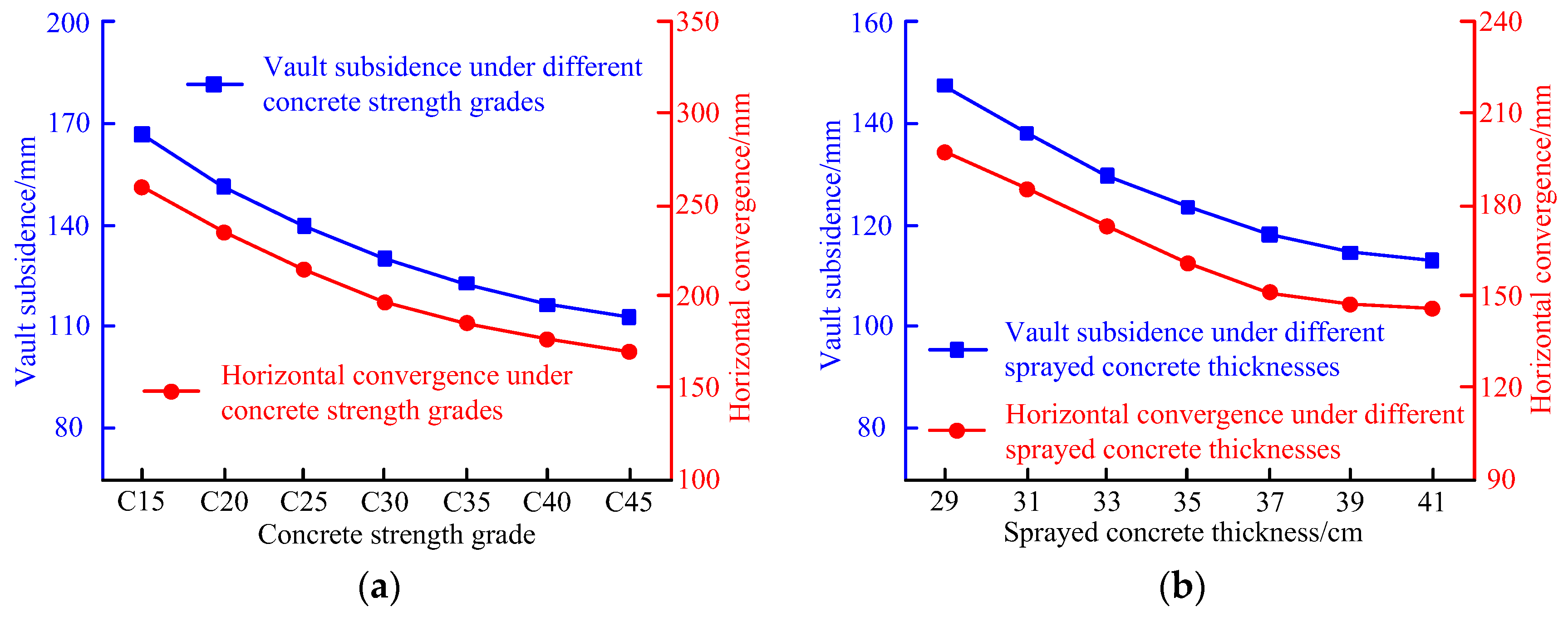
3.6. Analysis of Lining Parameter Optimization

An insufficient strength of the lining structure is a major factor for tunnel deformation, and the main factors affecting the strength of the lining structure are the strength grade of concrete, and the thickness of sprayed concrete. Based on the original support condition, lining parameters were changed for simulation and calculation, and an analysis of the lining parameter optimization was conducted. Seven concrete strength grades, i.e., C15, C20, C25, C30, C35, C40 and C45, and seven sprayed concrete thicknesses, i.e., 29 cm, 31 cm, 33 cm, 35 cm, 37 cm, 39 cm and 41 cm, were selected. The simulation results are displayed in Figure 9.
According to Figure 9, when the concrete strength grade is C15, the subsidence of the tunnel vault is 169.1 m and the maximum horizontal displacement is 247.5 m; when the grade rises to C45, they decline to 117.7 m and 165.9 m, respectively. When the sprayed concrete thickness is 29 cm, the two parameters are 151.2 m and 189.4 m, respectively. When the thickness increases to 41 cm, they decrease to 112.6 m and 147.3 m, respectively. On the whole, both the concrete strength grade and the sprayed concrete thickness greatly influence the tunnel deformation. When the grade or the thickness rises, the tunnel deformation decreases. In the optimization of lining parameters, according to the actual tunnel situation, the concrete strength grade should be no lower than C25, and the sprayed concrete thickness should be no less than 35 cm to satisfy the requirements of tunnel support.
Taking into consideration the influences of lining, anchor bolt, and steel arch parameters on tunnel deformation, the final support optimization scheme is provided in Table 3.

4. On-Site Application of the Optimization Scheme

According to the layout scheme of the original measuring points, the monitored data of tunnel deformation after the support optimization are shown in Figure 10. Phenomena, such as fracturing and bulging, no longer occur in the section where the support optimization scheme is adopted (Figure 11), which demonstrates that the safety performance of the scheme meets the requirements.
As exhibited in Figure 10, after the tunnel deformation stabilizes, the maximum subsidence of the vault reaches 58.1 mm, and the convergences of the upper and lower steps reach 66.7 mm and 51.2 mm, respectively. The deformation is significantly smaller than before, indicating that the optimized support design parameters can greatly constrain the surrounding rock deformation and effectively solve the problem of serious deformation of the tunnel in the fracture zone.

5. Conclusions

(1) During the tunnel construction, the deformation and stress of the tunnel vault and the upper step side wall are relatively large under the initial support of the original tunnel section, because limestone and diorite are in contact with the fracture zone. According to such on-site monitoring results, the initial support scheme needs to be optimized.
(2) Through numerical simulation and analysis on tunnel deformation under different initial support parameters, it is found that lining parameters and steel arch parameters have a greater effect on tunnel deformation than bolt reinforcement. Optimizing the parameters of the steel arch frame and lining can effectively improve the resistance of the initial support to large tunnel deformation. However, the deformation-restraining effect fails to be significantly improved after the support parameters are enhanced to a certain range.
(3) As can be seen from the on-site application results, the safety performance of the support optimization scheme has significantly improved. After the tunnel deformation stabilizes, the maximum subsidence of the vault reaches 58.1 mm, and the convergences of the upper and lower steps reach 66.7 mm and 51.2 mm, respectively. Since the stabilized tunnel deformation has met the operational requirements of the tunnel, and continuing to increase the support parameters does little to reduce the tunnel deformation but increases the cost, the initial optimized support method of the fracture zone tunnel in the light of the strength reduction method is favorable for the construction of the fracture zone of the Chunxuan Road Tunnel, and it provides a sufficient reference for the construction of similar engineering.

Author Contributions

Conceptualization, K.D. and L.W.; methodology, K.D.; software, B.R.; validation, C.J.; formal analysis, B.R.; investigation, S.W.; resources, L.W.; data curation, K.D.; writing—original draft preparation, K.D.; writing—review and editing, K.D.; visualization, S.W.; supervision, B.R.; project administration, C.J. All authors have read and agreed to the published version of the manuscript.

Funding

This study was supported by Natural Science Foundation of Jiangsu Province, China (Grant No. BK20200628).

Institutional Review Board Statement

Not applicable.

Informed Consent Statement

Not applicable.

Data Availability Statement

The data used to support the findings of this study are included within the article.

Acknowledgments

This study was supported by Natural Science Foundation of Jiangsu Province, China (Grant No. BK20200628) and the support is gratefully acknowledged.

Conflicts of Interest

The authors declare no conflict of interest.

References

  1. Bai, C.; Xue, Y.; Qiu, D.; Su, M.; Ma, X.; Liu, H. Analysis of Factors Affecting the Deformation of Soft Rock Tunnels by Data Envelopment Analysis and a Risk Assessment Model. Tunn. Undergr. Space Technol. 2021, 116, 104111. [Google Scholar] [CrossRef]
  2. Chen, J.; Liu, W.; Chen, L.; Luo, Y.; Li, Y.; Gao, H.; Zhong, D. Failure Mechanisms and Modes of Tunnels in Monoclinic and Soft-Hard Interbedded Rocks: A Case Study. Ksce J. Civ. Eng. 2020, 24, 1357–1373. [Google Scholar] [CrossRef]
  3. Tomanovic, Z. Effects of the Soft Rock Pre-consolidation on Time-dependent Deformations Around the Tunnel Excavation. Teh. Vjesn.-Tech. Gaz. 2015, 22, 401–406. [Google Scholar] [CrossRef]
  4. Guo, X.; Zhu, Y.; Tan, Z.; Li, L.; Li, A.; Yan, Y.-T. Research on Support Method in Soft Rock Tunnel Considering the Rheological Characteristics of Rock. Arab. J. Geosci. 2021, 14, 2703. [Google Scholar] [CrossRef]
  5. Sun, X.; Zhang, B.; Gan, L.; Tao, Z.; Zhao, C. Application of Constant Resistance and Large Deformation Anchor Cable in Soft Rock Highway Tunnel. Adv. Civ. Eng. 2019, 2019, 4347302. [Google Scholar] [CrossRef] [Green Version]
  6. Chen, Z.; He, C.; Wang, J.; Ma, C. Time-dependent Squeezing Deformation Mechanism of Tunnels in Layered Soft-rock Stratum Under High Geo-stress. J. Mt. Sci. 2021, 18, 1371–1390. [Google Scholar] [CrossRef]
  7. Wu, Z.; Zhang, B.; Weng, L.; Liu, Q.; Wong, L.N.Y. A New Way to Replicate the Highly Stressed Soft Rock: 3D Printing Exploration. Rock Mech. Rock Eng. 2020, 53, 467–476. [Google Scholar] [CrossRef]
  8. Mu, W.; Li, L.; Chen, D.; Wang, S.; Xiao, F. Long-term Deformation and Control Structure of Rheological Tunnels Based on Numerical Simulation and On-site Monitoring. Eng. Fail. Anal. 2020, 118, 104928. [Google Scholar] [CrossRef]
  9. Chen, Z.; He, C.; Xu, G.; Ma, G.; Wu, D. A Case Study on the Asymmetric Deformation Characteristics and Mechanical Behavior of Deep-Buried Tunnel in Phyllite. Rock Mech. Rock Eng. 2019, 52, 4527–4545. [Google Scholar] [CrossRef]
  10. Sun, X.; Zhao, C.; Tao, Z.; Kang, H.; He, M. Failure Mechanism and Control Technology of Large Deformation for Muzhailing Tunnel in Stratified Rock Masses. Bull. Eng. Geol. Environ. 2019, 80, 4731–4750. [Google Scholar] [CrossRef]
  11. Wu, K.; Shao, Z. Study on the Effect of Flexible Layer on Support Structures of Tunnel Excavated in Viscoelastic Rocks. J. Eng. Mech. 2019, 145, 04019077. [Google Scholar] [CrossRef]
  12. Chen, Z.; He, C.; Yang, W.; Guo, W.; Li, Z.; Xu, G. Impacts of Geological Conditions on Instability Causes and Mechanical Behavior of Large-scale Tunnels: A Case Study from the Sichuan-tibet Highway, China. Bull. Eng. Geol. Environ. 2020, 79, 3667–3688. [Google Scholar] [CrossRef]
  13. Li, G.; Hu, Y.; Tian, S.; Weibin, M.; Huang, H.-L. Analysis of Deformation Control Mechanism of Prestressed Anchor on Jointed Soft Rock in Large Cross-section Tunnel. Bull. Eng. Geol. Environ. 2021, 80, 9089–9103. [Google Scholar] [CrossRef]
  14. Tan, Z.; Li, S.; Yang, Y.; Wang, J. Large Deformation Characteristics and Controlling Measures of Steeply Inclined and Layered Soft Rock of Tunnels in Plate Suture Zones. Eng. Fail. Anal. 2022, 131, 105831. [Google Scholar] [CrossRef]
  15. Cao, C.; Shi, C.; Lei, M.; Yang, W.; Liu, J. Squeezing Failure of Tunnels: A Case Study. Tunn. Undergr. Space Technol. 2018, 77, 188–203. [Google Scholar] [CrossRef]
  16. Chu, Z.; Wu, Z.; Liu, Q.; Liu, B. Analytical Solutions for Deep-Buried Lined Tunnels Considering Longitudinal Discontinuous Excavation in Rheological Rock Mass. J. Eng. Mech. 2020, 146, 04020047. [Google Scholar] [CrossRef]
  17. Zhang, J.; Zhang, B. Reliability Analysis for Seismic Stability of Tunnel Faces in Soft Rock Masses Based on a 3d Stochastic Collapse Model. J. Cent. South Univ. 2019, 26, 1706–1718. [Google Scholar] [CrossRef]
  18. Fang, Z.; Zhu, Z.; Chen, X. Research on Construction Method and Deformation Control Technology of High Ground Stress Interbedded Soft Rock Tunnel. J. Intell. Fuzzy Syst. 2021, 40, 6175–6183. [Google Scholar] [CrossRef]
  19. Wu, K.; Shao, Z.; Qin, S.; Zhao, N. Mechanical Analysis of Tunnels Supported by Yieldable Steel Ribs in Rheological Rocks. Geomech. Eng. 2019, 19, 61–70. [Google Scholar]
  20. Liu, W.; Chen, J.; Luo, Y.; Chen, L.; Shi, Z.; Wu, Y. Deformation Behaviors and Mechanical Mechanisms of Double Primary Linings for Large-Span Tunnels in Squeezing Rock: A Case Study. Rock Mech. Rock Eng. 2021, 54, 2291–2310. [Google Scholar] [CrossRef]
  21. Du, D.; Dias, D.; Do, N. Effect of Surcharge Loading on Horseshoe-shaped Tunnels Excavated in Saturated Soft Rocks. J. Rock Mech. Geotech. Eng. 2021, 12, 1339–1346. [Google Scholar] [CrossRef]
  22. Feng, Q.; Jin, J.; Zhang, S.; Liu, W.; Yang, X.; Li, W. Study on a Damage Model and Uniaxial Compression Simulation Method of Frozen–Thawed Rock. Rock Mech. Rock Eng. 2022, 55, 187–211. [Google Scholar] [CrossRef]
  23. Schneider-Muntau, B.; Medicus, G.; Fellin, W. Strength Reduction Method in Barodesy. Comput. Geotech. 2018, 95, 57–67. [Google Scholar] [CrossRef]
  24. He, Y.; Wang, J.; Zhou, X.; He, Q.; Ai, S. Static and Stability Analyses of Pretensioned Latticed Arch Frame with Integrated Cable-Strut Arrangement. Thin-Walled Struct. 2019, 145, 106400. [Google Scholar] [CrossRef]
  25. Wang, Z.; Du, K.; Xie, Y.; Su, X.; Shi, Y.; Li, X.; Liu, T. Buckling Analysis of an Innovative Type of Steel-concrete Composite Support in Tunnels. J. Constr. Steel Res. 2021, 179, 106503. [Google Scholar] [CrossRef]
Figure 1. Geological section of the tunnel in the fracture zone.
Processes 10 01558 g001
Figure 2. Layout of measuring points for the tunnel. A is the vault subsidence monitoring point. B and C are the horizontal convergence monitoring points of the upper step of the tunnel. D and E are the horizontal convergence monitoring points of the lower step of the tunnel.
Processes 10 01558 g002
Figure 3. Monitoring curves for tunnel deformation.
Processes 10 01558 g003
Figure 4. Grid division of tunnel.
Processes 10 01558 g004
Figure 5. (a) Nephogram of vertical displacement and (b) nephogram of horizontal displacement. Nephograms of the displacement of the rock surrounding the tunnel.
Processes 10 01558 g005
Figure 6. Curves of contrast between the simulation results and measured data.
Processes 10 01558 g006
Figure 7. (a) Tunnel deformation curves under different steel arch specifications and (b) tunnel deformation curves under different steel arch spacings. Tunnel deformation curves under different steel arch frame parameters.
Processes 10 01558 g007
Figure 8. (a) Tunnel deformation curves under different bolt lengths and (b) tunnel deformation curves under different bolt spacings. Tunnel deformation curves under different bolt parameters.
Processes 10 01558 g008
Figure 9. (a) Tunnel deformation curves under different concrete strength grades and (b) tunnel deformation curves under different sprayed concrete thicknesses. Tunnel deformation curves under different lining parameters.
Processes 10 01558 g009
Figure 10. Monitoring curves of tunnel deformation after support optimization.
Processes 10 01558 g010
Figure 11. (a) Tunnel support construction and (b) tunnel after support. On-site condition of tunnel after support optimization.
Processes 10 01558 g011
Table 1. Initial support parameters of the tunnel section.
Surrounding Rock GradeC25 ShotcreteHollow Bolt/Low-Pre-Stressed BoltReinforcing MeshSteel Arch
Thickness/cmSpecificationLength/mSpacing/mSpecificationSpacing/mSpecificationSpacing/m
V29Φ2551.0 × 0.75Φ820 × 20 (double layers)I22b0.75
Table 2. Tunnel model parameters.
NameElastic Modulus/GPAPoisson’s RatioDensity/(kg·m−3)Cohesion/MPaInternal Friction Angle/(°)
Diorite0.020.2918000.02830
Limestone1.70.3520000.1225
C25 shotcrete260.22400//
Steel arch2100.37850//
Table 3. Optimization scheme for the initial support parameters of tunnel section.
Surrounding Rock GradeC25 ShotcreteHollow Bolt/Low-Pre-Stressed BoltReinforcing MeshSteel Arch
Thickness/cmSpecificationLength/mSpacing/mSpecificationSpacing/mSpecificationSpacing/m
V35Φ2551.0 × 0.5Φ820 × 20 (double layers)I28a0.5
Publisher’s Note: MDPI stays neutral with regard to jurisdictional claims in published maps and institutional affiliations.

