Article

The Influence of Rotating Speed on the Sealing Characteristics of a Liquid-Sealing Impeller for a Liquid Oxygen Turbopump

1
School of Mechanical Engineering, Northwestern Polytechnical University, Xi’an 710072, China
2
Research Center of Fluid Machinery Engineering and Technology, Jiangsu University, Zhenjiang 212013, China
*
Author to whom correspondence should be addressed.
Processes 2022, 10(7), 1366; https://doi.org/10.3390/pr10071366
Submission received: 15 June 2022 / Revised: 8 July 2022 / Accepted: 10 July 2022 / Published: 13 July 2022

Abstract

:
In order to explore the influence of rotating speed on the internal flow and sealing characteristics of the liquid-sealing impeller for a liquid oxygen turbopump of a rocket engine, unsteady numerical simulations of the flow characteristics and sealing performance of the first-stage liquid-sealing impeller for a liquid oxygen turbopump under liquid phase conditions were performed. The results show that the pressurization value increases with the increase in the rotating speed. The first-stage liquid-sealing impeller, whose structure is symmetrically distributed along the center of the rotation axis, tends to be an isobaric seal at a rotating speed of 12,000 rpm, and when the rotating speed is decreased or increased, it enters the leakage state or negative pressure sealing state, respectively. The matching relationship between the rotating speed and inlet pressure has a significant effect on the pressurization value, pressurization coefficient and leakage flow rate. Under the working condition with a good match between the rotating speed and inlet pressure, the pressurization value increases significantly and the leakage flow rate decreases significantly, and the pressurization coefficient is stable between 0.88 and 0.89. The empirical formulas proposed by Wood and the Shanghai Research Institute of Chemical Industry (1979) have high reference values for the design of the liquid-sealing impeller with a flow channel (groove) and retainer.

1. Introduction

As a core component of a liquid rocket engine, the main function of a turbopump is to increase the pressure of the liquid propellant carried by the rocket, and its reliability greatly affects the overall performance of the liquid rocket engine. Therefore, how to improve the reliability of the turbopump in the design process is very important [1]. One of the key technologies in the design of a turbopump is the sealing of a low-temperature propellant. A multistage liquid-sealing impeller was adopted in the liquid oxygen turbopump of a liquid oxygen kerosene engine to reduce the leakage of liquid oxygen and to provide the guarantee of the safe and reliable operation of the rocket engine. The liquid-sealing impeller seal belongs to one of the non-contact dynamic seals (that is centrifugal sealing), which mainly rely on the rotation of the sealing impeller to work on the fluid medium, and through the action of centrifugal force, the fluid medium leaking on the low-pressure side is thrown out, and the pressure balance with the leaking medium is achieved to realize the sealing effect [2]. This seal has a simple structure and works in a non-contact state without friction between the dynamic and static faces. It has a reliable operation, long service life and can basically be maintenance-free [3]. Due to the above-mentioned advantages of centrifugal sealing, it has become one of the hotspots in modern sealing research.
The related research on this kind of seal can be traced back to the middle of the twentieth century. In terms of engineering applications, Schnetzer [4] designed and manufactured a centrifugal sealing structure with a hollow rotating disc, and conducted experiments with water and silicone oil as the fluid mediums, respectively, to verify the sealing performance, and obtained certain data, such as the maximum sealing pressure and power at each rotating speed, and the leakage under continuous operation. Nazmul [5] adopted the centrifugal sealing of the auxiliary impeller in a sewage pump. Compared to the traditional seal, he found that the initial cost and power consumption of the centrifugal sealing were high, but during continuous operation, the centrifugal sealing had a lower cumulative cost over the life of the pump.
In terms of the theoretical research, since it is very important to determine the size of the pressurization coefficient in the design of centrifugal sealings, many researchers have studied the coefficient. Initially, limited by the theoretical level, the research on the pressurization coefficient was limited to the theoretical formula obtained through experiments. Wood et al. [6] obtained the pressurization coefficient of centrifugal sealing with different blade structures by the experimental method. Tolubev [7] studied the anti-compression head of different centrifugal sealing impellers, and obtained the Tolubev curve, which provided a reference for later designers. Liu [8] obtained the calculating formula of the pressurization coefficient through theoretical derivation, and compared it with the formula of the pressurization coefficient summarized by his predecessors. Many scholars have also conducted theoretical research on centrifugal sealing in other aspects. Yu [9] pointed out that the medium in the centrifugal sealing of the auxiliary impeller is mainly rotational movement without significant flow in the radial direction, and the vortex flow of the flow field is the key factor affecting the sealing performance. At the same time, the influence of the structural parameters of the auxiliary impeller on the sealing performance was explored, and the general principles that should be followed in the structural design of the auxiliary impeller were presented. Yan et al. [10] established a mathematical model and theoretically derived an analytical solution for the calculation of the radius of the auxiliary impeller, aiming at improving the sealing pressure capability and axial force balance ability of the centrifugal sealing of the auxiliary impeller. Dessauer et al. [11], Nalardone et al. [12] and Shiels [13] also successively conducted research on the basic principles of centrifugal sealing of the auxiliary impeller, the principle of balancing axial force and the basic principles of design.
With the development of CFD technology, the research on centrifugal sealing based on the numerical simulation method has become a hotspot. Li [14] analyzed the flow characteristics and centrifugal sealing mechanism of the flow field in the seal on the basis of experiments and numerical simulations, and analyzed and predicted the sealing ability and performance. Zhi [15] studied continuous injection-discharge centrifugal sealing, introduced the sealing principle and characteristics of the seal, conducted numerical simulations and tests on its sealing performance and explored the effects of various operating conditions, structural parameters and structural forms on the performance of continuous injection-discharge centrifugal sealing. Ma et al. [16] studied the sealing performance of the centrifugal sealing of a high-speed impeller in the liquid oxygen turbopump, and analyzed the phase distribution in the flow channel and the sealing power consumption. The results show that the sealing capacity of the fully liquid-filled impeller increases with the increase in rotating speed, blade size and fluid medium density, and the centrifugal sealing of the high-speed impeller is suitable for low-temperature rocket systems. Ma et al. [2] conducted an optimization study on the centrifugal sealing of the auxiliary impeller in a self-controlling and self-priming pump without seal, and designed the auxiliary impeller with the design method of a low specific speed impeller to improve the hydraulic efficiency of the auxiliary impeller, thereby increasing the sealing pressure of the auxiliary impeller. The design method has certain feasibility through CFD simulation verification and test verification.
In summary, due to the unique advantages of centrifugal sealing in fluid sealing, it is widely used in many fields, and related research is also gradually developing. To date, there is little research on the liquid-sealing impeller of a liquid oxygen turbopump that adopts a liquid oxygen kerosene engine, especially the research on a liquid-sealing impeller with a flow channel (groove) and retainer. Therefore, there is a lack of comprehensive understanding of the internal flow field and sealing characteristics in this type of liquid-sealing impeller. In addition, in the multistage liquid-sealing impeller studied in this paper, the radial dimension of the first-stage liquid-sealing impeller with a flow channel (groove) and retainer is significantly larger than that of the second-stage liquid-sealing impeller, so it plays the main sealing function in a normal operation. Based on the above-mentioned reasons, the internal flow field of the first-stage liquid-sealing impeller with a flow channel (groove) and retainer is numerically simulated, and the influence of rotation speed on the internal flow field and sealing characteristics of the first-stage liquid-sealing impeller are analyzed, which could provide a certain reference for the design and optimization of the multistage liquid-sealing impeller.

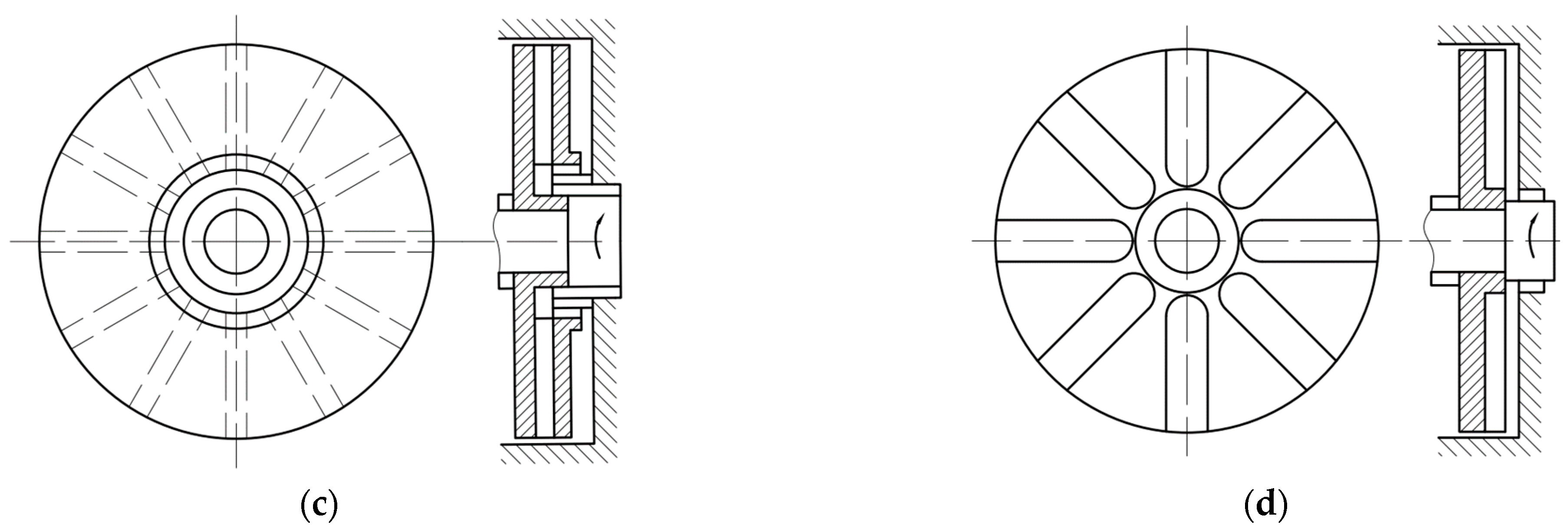
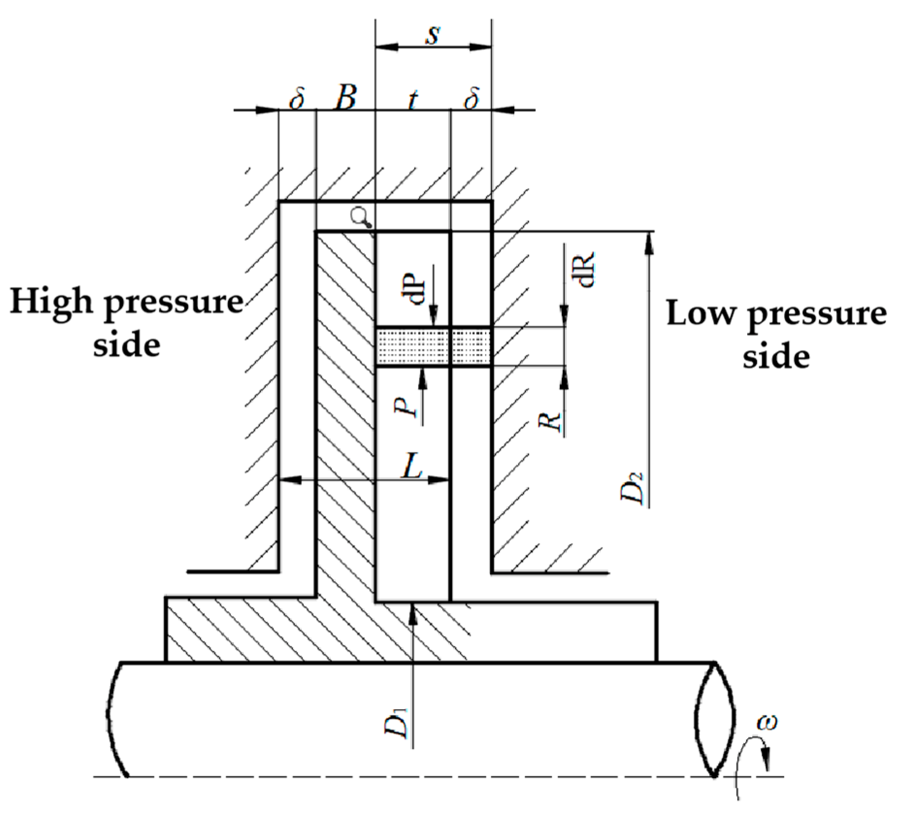
2. The Sealing Principle of the Liquid-Sealing Impeller

The seal of the liquid-sealing impeller belonged to centrifugal sealing in the non-contact seal. The centrifugal sealing mainly relies on the rotation of the impeller to work on the liquid. Through the action of centrifugal force, the fluid medium leaking on the low-pressure side was thrown out, and the pressure of the leaking fluid medium from the inlet was offset to avoid the fluid medium leaks on the low-pressure side, thus realizing the sealing effect. When the centrifugal pressure generated by the impeller was equal to the pressure of the leaking fluid medium, there was no leakage of the fluid medium from the high-pressure to the low-pressure side. In this case, an “isobaric seal” state was formed. When the centrifugal pressure was higher than the pressure of the leaking medium, the leaking medium was pushed back to the inlet by the higher centrifugal pressure, thus forming a “negative pressure sealing” state [17].
The centrifugal sealing impeller, whose structure is symmetrically distributed along the center of the rotation axis, mainly includes open, semi-open, and closed impellers. The open impeller mainly includes two types: an open impeller with blades and an open impeller with a flow channel (groove). The basic structures of the above impellers are shown in Figure 1 [18].
The multistage liquid-sealing impeller of the liquid oxygen turbopump studied in this paper realized the sealing effect by reducing the pressure of the fluid medium step by step through the circumvolution of two centrifugal sealing impellers. The three-dimensional model of the multistage liquid-sealing impeller is shown in Figure 2. After the high-pressure fluid medium enters from the inlet, it passes through the first-stage liquid-sealing impeller, the disengaged face seal, the second-stage liquid-sealing impeller and the normally closed face seal, where the face seal is set at the inner diameter of the liquid-sealing impeller. Since the centrifugal sealing can only play a sealing role when it rotates at a high rotating speed, the detachable face seal plays the main sealing role before the engine works. After the engine is started, the detachable seal is opened to form a gap. At this time, the main sealing function is undertaken by the liquid-sealing impeller. When the first-stage liquid-sealing impeller is not completely sealed, the fluid medium enters the secondary liquid-sealing impeller from the gap between the disengaged face seal and the shell through the first liquid-sealing impeller, and the second-stage liquid-sealing impeller blocks the medium again, and the normally closed face seal after the second-stage impeller can further prevent the fluid medium from leaking in the axial direction. Since the first-stage impeller of the multistage liquid-sealing impeller has a larger radial dimension than the second-stage liquid-sealing impeller, it assumes the main sealing function in normal operations.
The first-stage liquid-sealing impeller of the multistage liquid-sealing impeller is an open impeller with a flow channel (groove). Compared to the common open impeller with a flow channel (groove), the first-stage liquid-sealing impeller is also provided with a retainer structure on its outer edge. When the outer edge of the impeller is closed by the retainer, the momentum exchange and liquid friction torque along the outer diameter are reduced, which can reduce the power consumption of the impeller [18]. The second-stage liquid-sealing impeller of the multistage liquid-sealing impeller is a common open impeller with blades. The schematic diagrams of the two types of impellers are shown in Figure 3.

3. Research Model and Numerical Calculation Method
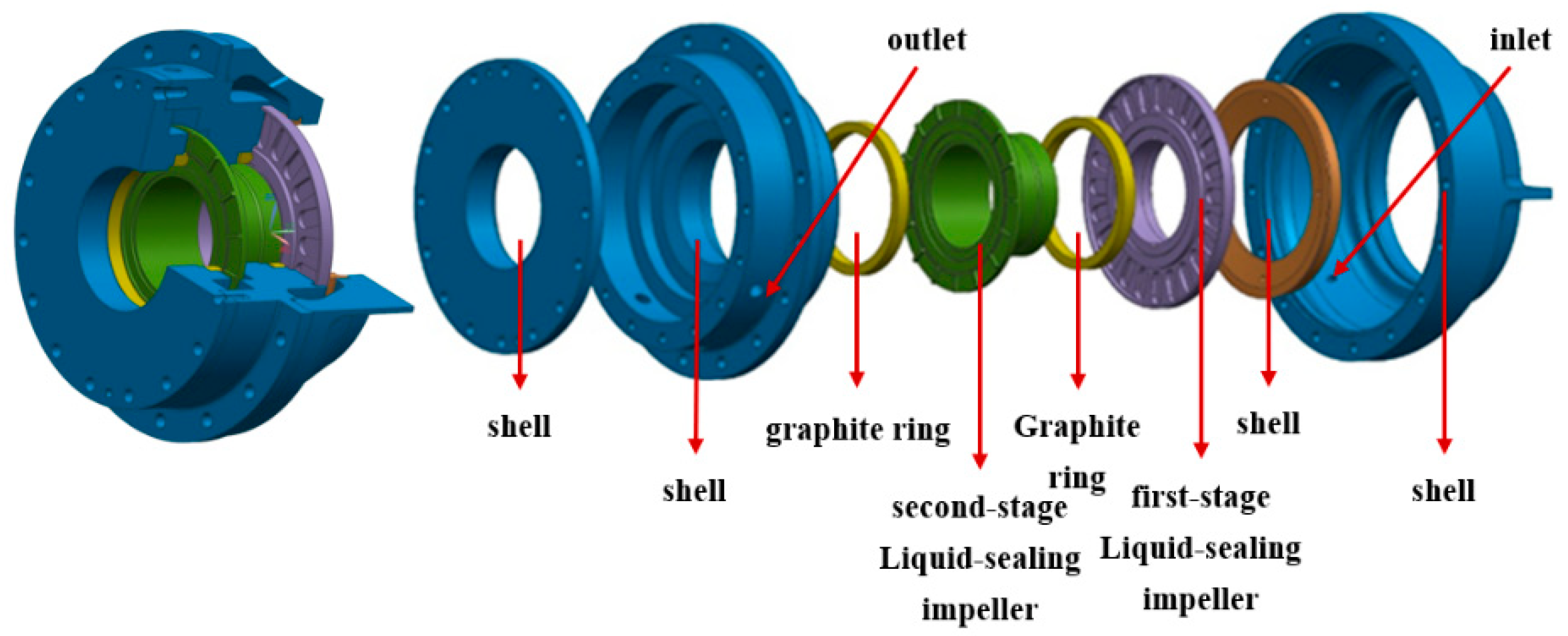
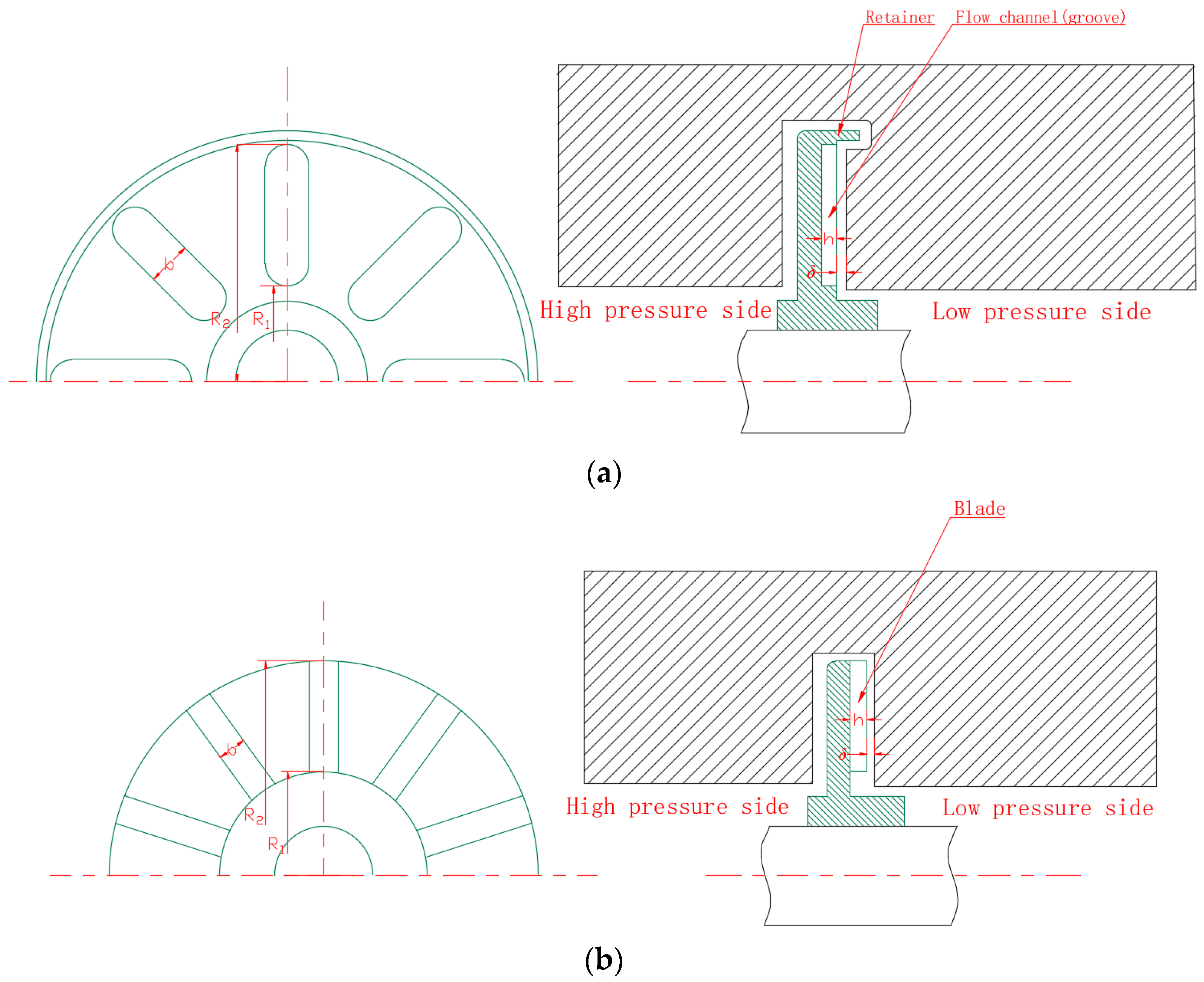
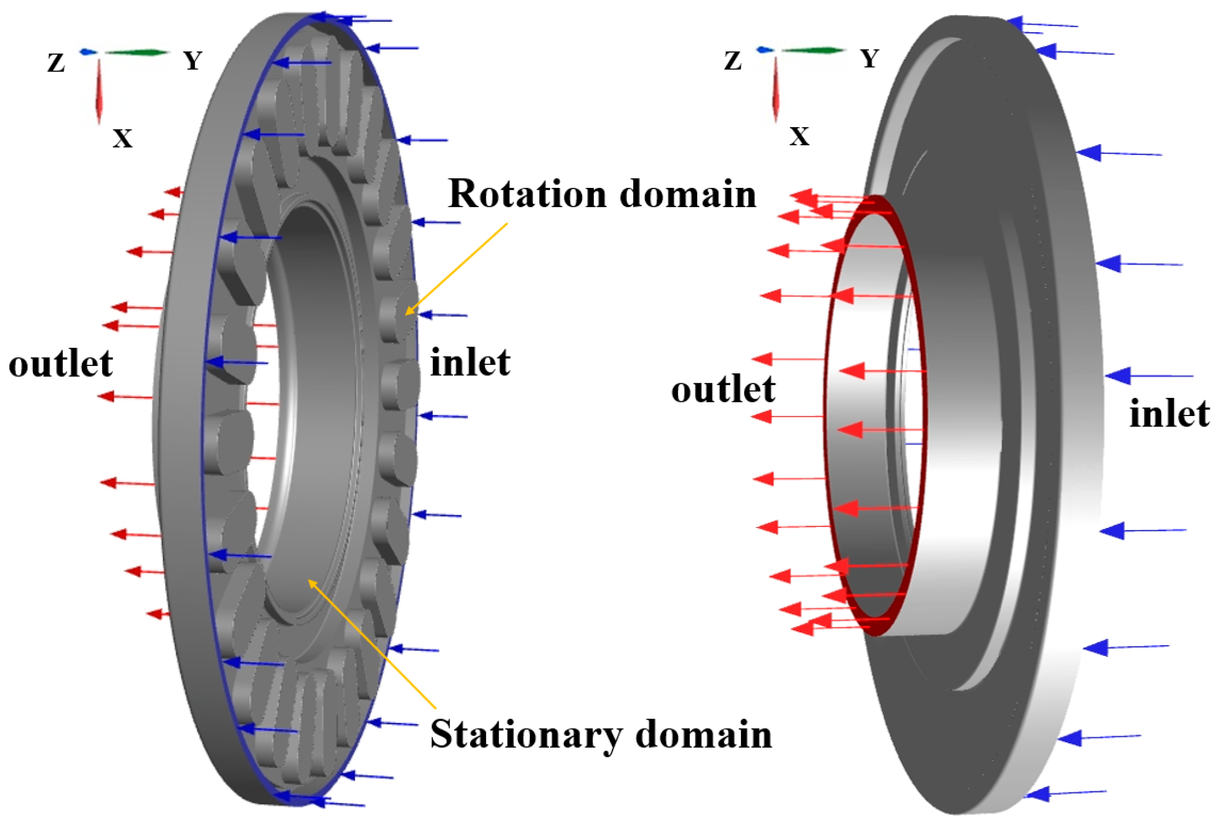
3.1. Research Model

In this paper, a Siemens NX 9.0 was used to construct a 3D model of the internal flow field for the first-stage liquid-sealing impeller. The pressure distribution of the first-stage liquid-sealing impeller was obtained through the previous numerical simulation, as shown in Figure 4. It can be observed that the pressure distribution of the front cavity of the first-stage liquid-sealing impeller is uniform, and the pressure of P1 and P2 are 2.999 MPa and 2.996 MPa, respectively, and the deviation is about 0.1 %. It can be observed that the presence or absence of the flow field in the front cavity has little effect on the actual inlet conditions of the first-stage liquid-sealing impeller. Therefore, the pressure inlet boundary condition can be set directly near the actual inlet of the first-stage liquid-sealing impeller.
Based on the above reasons, in order to reduce the time of numerical simulations, the flow field of the first-stage liquid-sealing impeller was simplified in this paper, and the large volume of the front cavity was deleted to reduce the volume of the computational domain and the grid number. The final computational domain is shown in Figure 5, the main structural parameters of the first-stage liquid-sealing impeller are shown in Table 1.

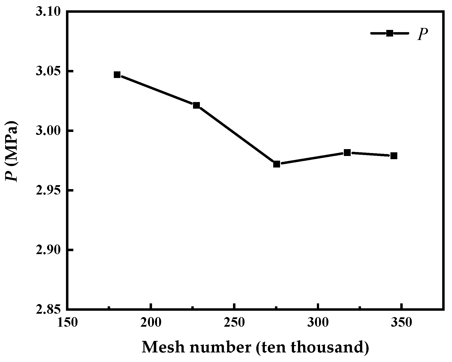
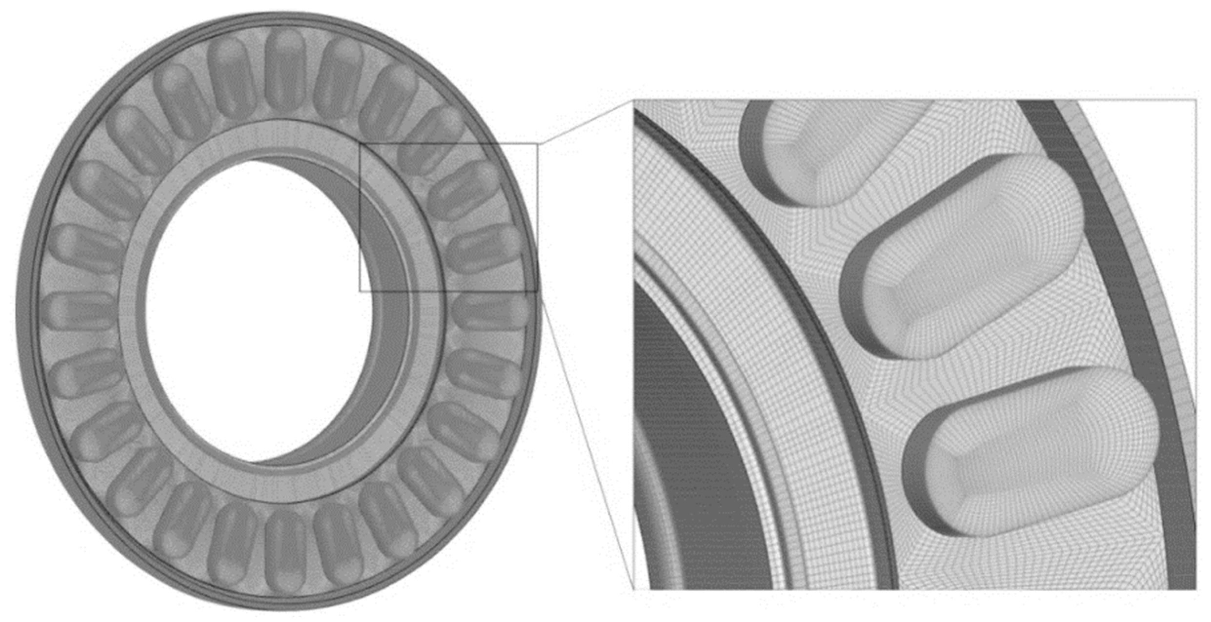
3.2. Grid Independence Verification

In this paper, ICEM CFD was used to mesh the computational domain of the first-stage liquid-sealing impeller. A structured grid division was adopted, and local encryption was performed on relatively small parts of the computational domain, such as rounded corners, to ensure that the computational domain grid tended to the real boundary of the computational domain.
In addition, in order to determine the appropriate number of grids, the groove top pressure of the first-stage liquid-sealing impeller was selected as the standard to verify the grid independence, as shown in Table 2.
Figure 6 is the grid independence analysis. It can be observed from Figure 6 that when the total number of grids reaches 2,754,456, the pressure tends to be stable. Continuing to increase the total number of grids has no significant effect on the calculation results. Considering the calculation efficiency and calculation time, the grid scheme with a total of 2,754,456 was selected for the following numerical simulation, which is shown in Figure 7. The y+ value of the entire computational domain was always lower than 20.

3.3. Numerical Calculation Method

3.3.1. Turbulence Model Selection

In this paper, the SST k-ω turbulence model, which is more suitable for simulating the strong swirling flow and separation flow, was used to numerically calculate the fluid seal rotation field, because the SST k-ω model is a turbulent flow model formed by the combination of the standard k-ε and Wilcox k-ω models produced by Menter [19]. In the flow field calculation process, the Wilcox k-ω model was used to analyze the near-wall area, and the standard k-ε model was used to analyze the far-wall area. The SST k-ω model combines the advantages of the two calculation models well, and can accurately predict flow characteristics in the flow fields.

3.3.2. Boundary Conditions and Calculation Settings

The inlet boundary condition of the computational domain adopts the pressure inlet, and the outlet boundary condition adopts the pressure outlet. Table 3 shows the basic settings of the numerical simulation calculation of the first-stage liquid-sealing impeller.
The wall boundary condition was chosen as the no-slip wall. The coupled solver was used, and the gradient and pressure were too discrete based on Least Squares Cell Based and PRESTO! In addition, the first-order upwind mode was used for the discrete residual term, and the default parameters were used for each relaxation factor.
The physical parameters of the fluid medium presented in this paper are shown in Table 4. In the numerical calculations, each physical parameter of the medium was assumed to be constant and the boundary conditions of each wall were adiabatic.

3.3.3. Numerical Calculation and Experimental Verification

In order to verify the accuracy of the numerical method, experiments were performed relying on the test equipment of the Xi’an Aerospace Propulsion Institute. At the same time, considering the safety of the test operation, liquid nitrogen was used instead of liquid oxygen as the test liquid to measure the performance of the multistage liquid-sealing impeller. During the test, the pressure of the sealing chamber at the monitoring point P26 (shown in Figure 8) of the first-stage liquid sealing impeller was collected. The experimental data were compared with the numerical calculation results under liquid nitrogen, as shown in Table 5. It can be observed from Table 5 that the numerical simulation values under liquid nitrogen are relatively close to the experimental values, and the deviations of the first-order and second-order upwind schemes are 6.67% and 6.50%, respectively. Therefore, the numerical calculation method has certain applicability and accuracy and can be used for the subsequent numerical study of the sealing characteristics of the liquid-sealing impeller for a liquid oxygen turbopump.

4. Results and Analysis

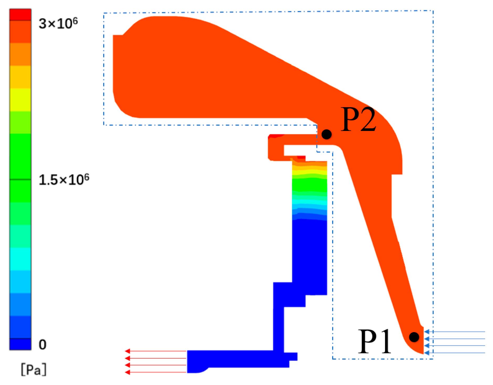
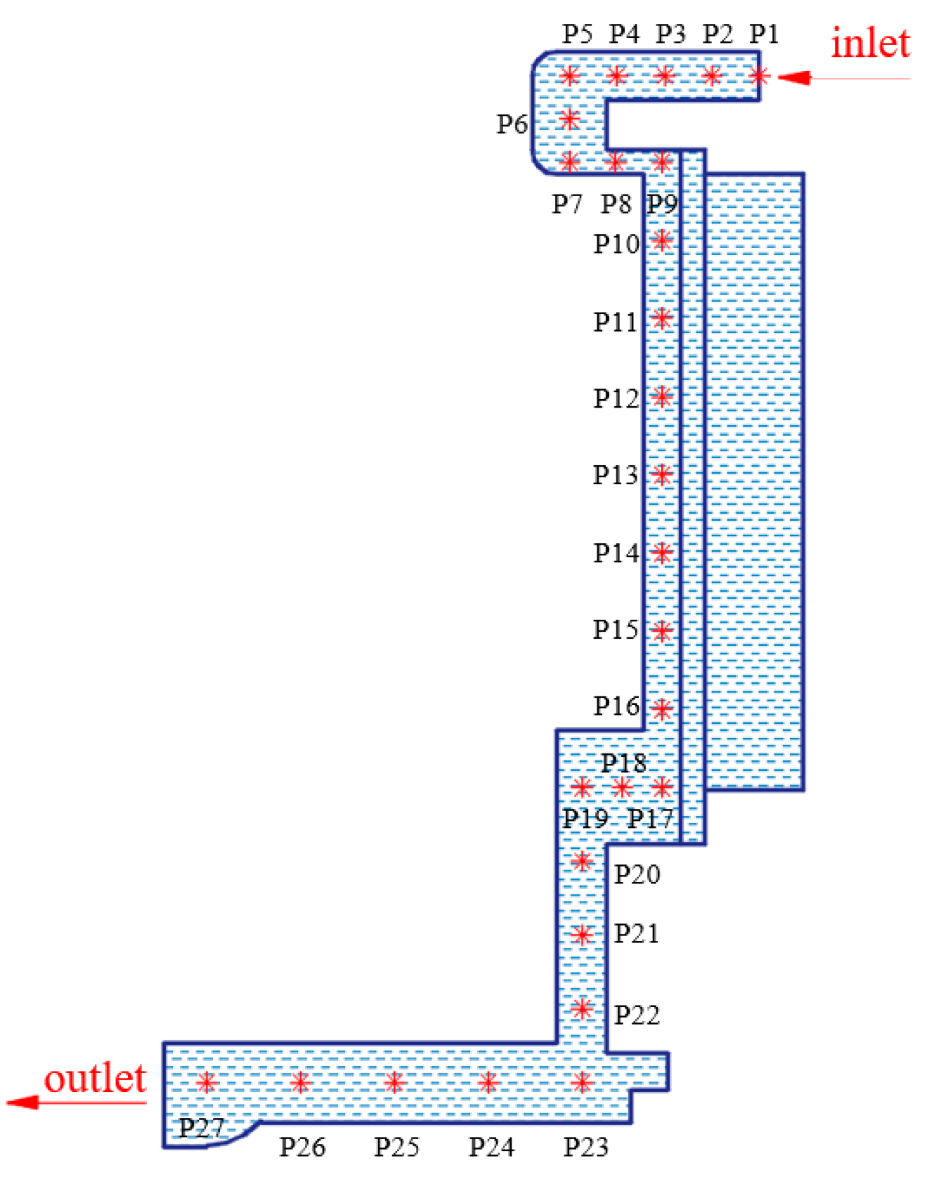
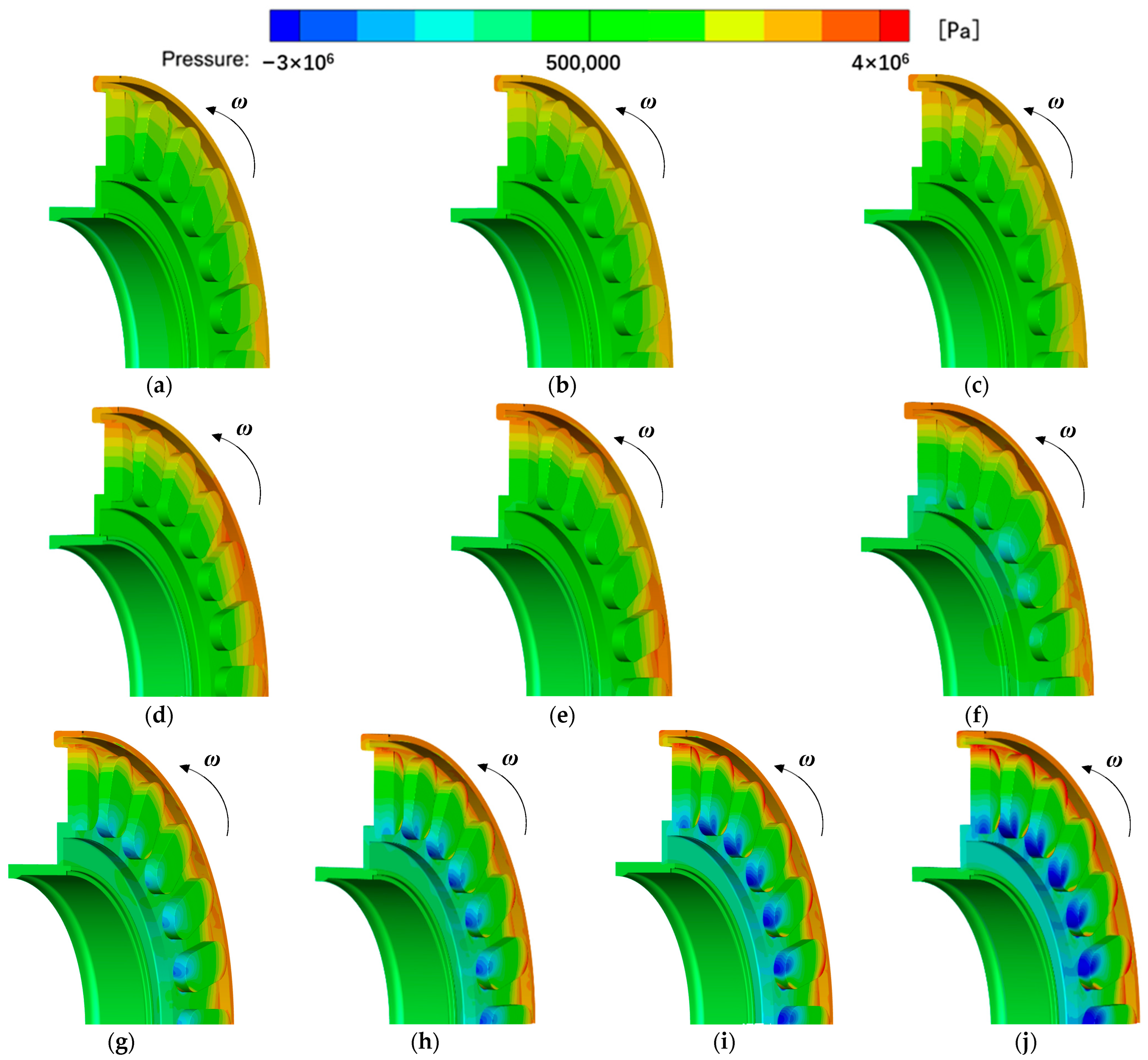
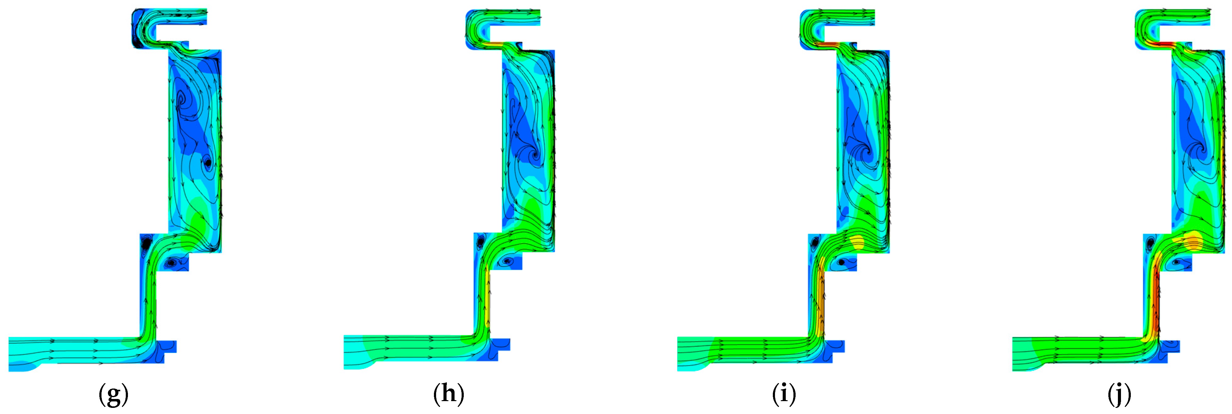
4.1. The Influence of the Rotating Speed on the Flow Field of the Liquid-Sealing Impeller

Figure 9 shows the pressure distribution of the first-stage liquid-sealing impeller at different rotating speeds. At a low rotating speed, the high pressure of the flow field is mainly distributed near the inlet of the liquid-sealing impeller, and the pressure gradient of the flow field in the groove is not obvious. At a high rotating speed, the pressure gradient of the flow field in the groove tends to be obvious, and the pressure gradients at the top and root of the groove are the most significant. The high pressure is mainly distributed at the top of the groove, the pressure surface at the root of the groove is also formed by local high pressure and the suction surface at the root of the groove is distributed with a low-pressure area. With the increase in the rotating speed, the low-pressure area in the groove root further increases and gradually extends in the radial direction.
By comparing the pressure distribution of the first-stage liquid-sealing impeller at different rotating speeds, it can be observed that the pressure from the inlet to the outlet of the first-stage liquid-sealing impeller is reduced in different degrees, and the liquid-sealing impeller has a centrifugal effect on the high-pressure fluid medium from the inlet. The rotating speed has a significant impact on the pressure distribution of the liquid-sealing impeller. At a high rotating speed, the first-stage liquid-sealing impeller has a stronger centrifugal effect on the fluid medium. After the fluid medium flows into the groove, the fluid is squeezed to the pressure surface of the groove root due to the high-speed rotation of the impeller, a local high-pressure area is formed on the pressure surface of the groove root and a low-pressure area is formed on the suction surface of the groove root. The low-pressure area gradually extends from the root to the top of the groove against the suction force, with the increase in the rotating speed.
In order to further analyze the pressure change in the first-stage liquid-sealing impeller, monitoring points were set in the flow channel, as shown in Figure 8. To quantitatively demonstrate the relationship between the pressure variation and the location of the monitoring points, the dimensionless time-averaged pressure coefficient C ¯ p was defined and its expression is shown in Equation (1).
C ¯ p = p p i n 0.5 ρ l U t 2  
where Ut is the tangential linear velocity of the groove outer diameter, (m/s); ρl is the density of the fluid medium (kg/m3).
Figure 10 shows the change curve of the time-averaged pressure coefficient along the flow channel at different rotating speeds, where the abscissa is the ratio of the inlet distance x from the current position along the flow channel to the total length L of the flow channel. By comparing the distribution of the pressurization coefficient at each rotating speed, it can be found that the pressurization coefficient increases with the increase in the rotating speed. When x/L is between 0~0.17, there is no significant difference in the pressurization coefficient, and the pressurization coefficient curve is basically in a horizontal state. When x/L reaches 0.17, the pressurization coefficient at different rotating speeds is differentiated to a great extent, and the pressurization coefficient increases slightly under high-rotating-speed conditions, and decreases under low-rotating-speed conditions. The lower the rotating speed, the more the pressurization coefficient decreases. When x/L is between 0.22~0.6, the pressurization coefficient at each rotating speed decreases in approximately the same trend, and the decreasing range is basically the same. When x/L is between 0.6~0.8, the change in the pressurization coefficient under each rotating speed is obviously differentiated again. The pressurization coefficient of the low-rotating-speed condition continues to decrease, and the decreasing range gradually increases with the decrease in the rotating speed. The pressurization coefficient at the high rotating speed basically remains constant at first, and then increases slightly. When x/L is between 0.8~1.0, the pressurization coefficient at a low rotating speed first decreases and then slowly increases, but it does not change at a high rotating speed, and the pressurization coefficient curve is horizontal.
For the centrifugal sealing represented by a liquid-sealing impeller, it is very important to generate a sufficient centrifugal pressurization capacity. The fluid medium generates pressurization ΔP under the fluid medium of the impeller. For the first-stage liquid-sealing impeller, the pressure difference between the groove top and the groove root is the pressurization value of the liquid-sealing impeller. Figure 11 shows the pressurization value of the first-stage liquid-sealing impeller at each rotating speed. As can be observed from the figure, due to the different working powers of the liquid-sealing impeller at different rotating speeds, the rotating speed has a great influence on the pressurization value. When the pressurization value is between 0.8~5 MPa, it increases with the increase in the rotating speed. It is worth noting that, after the rotating speed reaches 11,000 rpm, there is a significant increase in the pressurization value, which is mainly due to the fact that at low rotating speeds of 11,000 rpm and below, the high-pressure of 3 MPa from the inlet rapidly flows through the impeller, which is driven by a considerable difference between the inlet and outlet, and the essence of the liquid-sealing impeller pressurization is that the impeller drives the fluid medium to rotate. Due to the low rotating speed, the high-speed flowing fluid medium cannot be fully driven by the impeller to rotate and flow through the impeller. When the rotating speed continues to increase, the inlet pressure of the fluid medium is better matched with the rotating speed and the leakage flow rate is reduced. During the flow process, the rotation of the impeller increases, and the liquid-sealing impeller has a good pressurization effect, and the pressurization value is obviously improved. This phenomenon also shows that, in the design process of the liquid-sealing impeller, the match between the rotating speed of the liquid-sealing impeller and the inlet pressure is very important, and a better sealing effect can be achieved when the rotating speed and inlet pressure are well matched.
Figure 12 shows the velocity distribution of the flow field in the YZ plane for each rotating speed. From the streamlines, it can be observed that there are large-scale eddy flows in the groove at each rotating speed. The sealing ability of an open impeller is closely related to the vortex flow in the flow channel (groove) or between the blades, so the appearance of the vortex has a positive effect on improving the sealing performance [1]. When the rotating speed is between 8000~11,000 rpm, the liquid-sealing impeller cannot form an effective seal against the leakage of 3 MPa, and the flow field presents an obvious leakage state. The leaked fluid medium continuously flows from the gap between the impeller and the sealing shell to the outlet, and the leakage flow rate decreases with the increase in the rotating speed. When the rotating speed is 12,000 rpm, the liquid-sealing impeller tends to be in an isobaric sealing state. At this time, the velocity of the flow field decreases significantly, and the streamline at the outlet is chaotic. When the rotating speed of the impeller is between 13,000~17,000 rpm, the pressurization capability of the liquid-sealing impeller is enhanced, the flow direction of the medium is from the outlet to the inlet and the flow velocity increases with the increase in the rotating speed. At this time, the seal is in a negative pressure sealing state.
Through the analysis of the three-dimensional streamlines shown in Figure 13, it is found that, in the rotating speed range of 8000~17,000 rpm, the first-stage liquid-sealing impeller groove area generally presents three flow states. In the leakage state, most of the leakage medium from the inlet flows to the outlet through the gap between the impeller and shell, and a small amount enters the groove area from the root of the groove. The medium in the groove flows to the top of the groove under the centrifugal drive to form a vortex, and part of the fluid flows out of the groove; it flows again to the root area of the next groove under the action of the gap leakage fluid. In the state of isobaric sealing, the fluid generally flows tangentially without an obvious radial flow. After entering the groove, a vortex is formed, and after flowing out of the groove, it continues to flow tangentially to the next groove. In the state of negative pressure sealing, the fluid enters the groove from its root, a part of which is close to the pressure surface of the groove and flows to the top of the groove, and the other part flows from the pressure surface to the suction surface and then moves against the suction to the top of the groove, and then flows to the pressure surface again. Finally, the fluid flows to the top of the groove together to form a vortex. After flowing out of the groove, a part of the fluid flows to the inlet in the radial direction, and a part enters the next groove in the tangential direction.

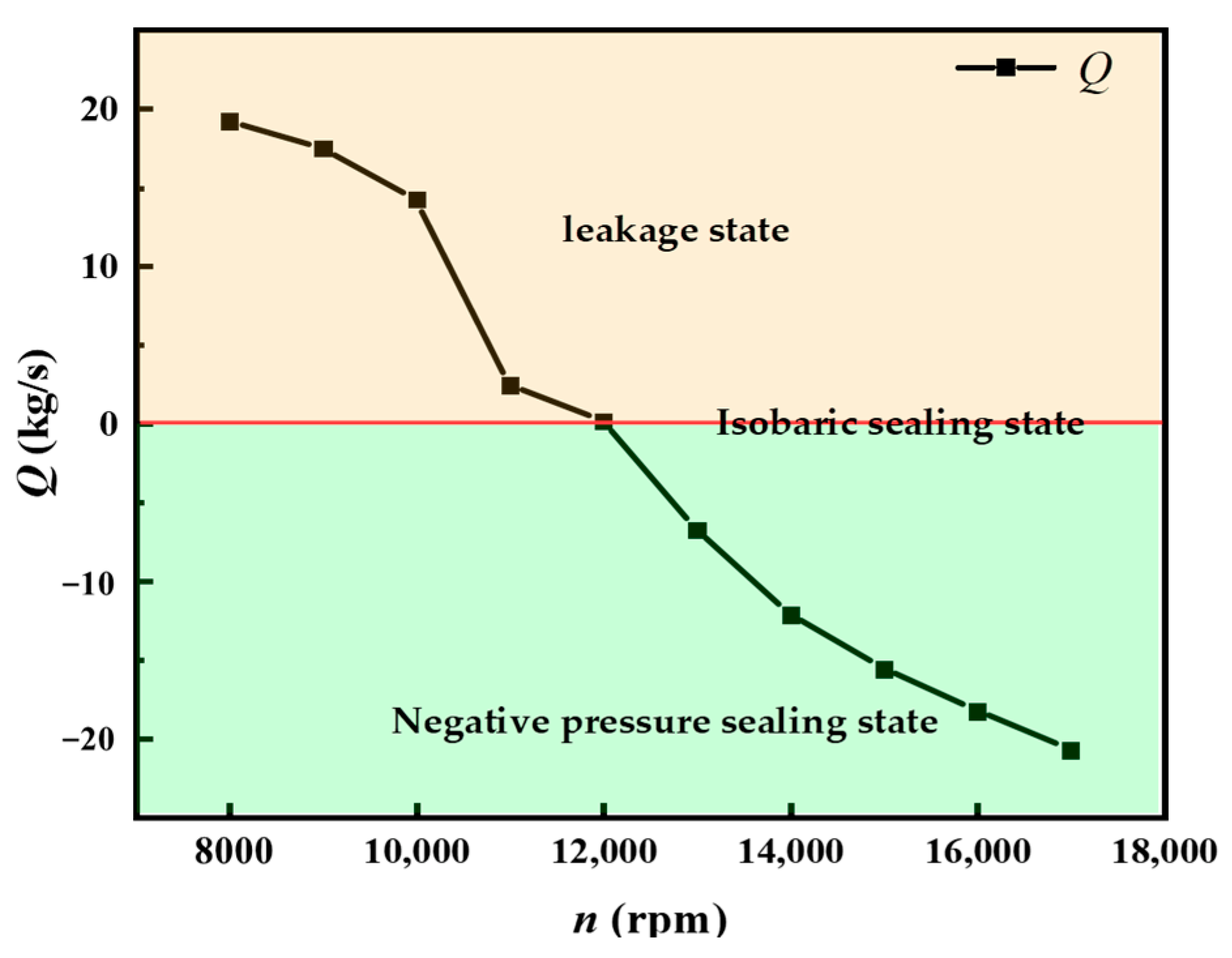
4.2. The Influence of Rotating Speed on the Leakage Flow Rate of the Liquid-Sealing Impeller

From the flow rate of the outlet monitored in Figure 14, it can be observed that the first-stage liquid-sealing impeller is in a leaking state at 8000~11,000 rpm. At this time, the liquid-sealing impeller cannot form an effective seal due to the low rotating speed, and the fluid medium constantly passes through the first-stage liquid-sealing impeller. However, as the rotating speed continues to increase, the leakage flow continues to decrease. After 11,000 rpm, the flow rate has a relatively obvious sudden change. This is because after the rotating speed reaches 11,000 rpm, the inlet pressure and rotating speed are well match, the centrifugal pressure generated by the rotating impeller gradually approaches the inlet and outlet pressure difference and the sealing function of the rotating impeller obviously inhibits the flows of the inlet fluid medium, which in turn leads to a significant decrease in the leakage flow. It can be observed that, for the inlet pressure of 3 MPa, after the rotating speed reaches 11,000 rpm, the first-stage liquid-sealing impeller can better play a sealing role. When the rotating speed reaches 12,000 rpm, the outlet flow of the first-stage liquid-sealing impeller tends to 0, that is, complete sealing is basically achieved. At this time, the first-stage liquid-sealing impeller is in an isobaric sealing state. When the rotating speed reaches 13,000 rpm, the strong centrifugal action of the first-stage liquid-sealing impeller causes the fluid medium show a reverse-flow state from the outlet to the inlet, and the flow rate increases with the increase in the rotating speed. At this time, the first-stage liquid-sealing impeller is in a negative pressure sealing state.

4.3. The Influence of the Rotating Speed on the Pressurization Coefficient of the Liquid-Sealing Impeller

In a theoretical calculation, the magnitude of the pressurization value can be calculated according to Formulas (2) to (4) in combination with Figure 15 [8].
d P = ρ ω 2 R d R  
P 1 P 2   d P = R 1 R 2 ρ ω 2 R d R  
Δ P t = P 2 P 1 = 1 2 ρ ω 2 R 2 2 R 1 2  
where ρ is the density of the fluid medium (kg/m3); ω is the rotating angular velocity of the impeller (rad/s); R1 is the inner diameter of the impeller (mm); R2 is the outer diameter of the impeller (mm); P1 is the pressure at the bottom of the groove and P2 is the pressure at the top of the groove.
The calculation formula presented above was obtained in an ideal state, that is, it was assumed that the axial gap δ was close to 0, and the fluid medium in the sealing cavity rotated at the rotating angular velocity ω, so it was also called the theoretical liquid sealing capacity. In fact, as a non-contact seal, δ is not zero, and the liquid in the seal cavity is not an ideal medium without viscosity, and its actual rotating speed is not equal to the rotating speed of the impeller, but is between 0.5 ω~ω [20]; there is a ratio φ 2 between the actual pressurization value ΔP and the theoretical pressurization value ΔPt, which is called the pressurization coefficient, and its value can be calculated according to Formula (5).
φ 2 = Δ P Δ P t
There are many factors that affect the pressurization coefficient, and it is generally believed that its magnitude is related to the axial gap between the impeller and the shell, the height (depth) of the blade (groove), the fluid medium, the flow state of the flow field and the working conditions. Since there are many influencing factors, especially the fact that the flow state in the seal is often difficult to determine, it is very important to accurately understand the pressurization coefficient of the first-stage liquid-sealing impeller.
There have been many studies on the pressurization coefficient. Table 6 presents the empirical formula of the pressurization coefficient presented by some other researchers [8]. It can be observed from Table 5 that most of these empirical formulas only consider the influence of some structural parameters, and do not consider the influence of the working conditions, such as rotating speed, inlet pressure and fluid medium.
Based on the empirical formula presented above, substitute the relevant structural parameters of the first-stage liquid-sealing impeller, query the measured curve or calculate the theoretical pressurization coefficient φt2 under each empirical formula. At the same time, the numerical simulation calculation results are post-processed, and the numerical simulation pressurization coefficient φ 2 is obtained, as shown in Table 7.
It can be observed in Table 6 that pressurization coefficient φ 2 is relatively small at a low rotating speed. When the rotating speed reaches 11,000 rpm, the pressurization coefficient φ 2 becomes stable and remains at around 0.88~0.89, which also shows that the rotating speed has an influence on the pressurization coefficient.
The stable pressurization coefficient when the rotating speed and the inlet pressure are well matched is compared to the empirical formula calculation results presented by some other researchers, as shown in Figure 16. It can be observed from the figure that the empirical formulas obtained by different researchers are quite different, mainly because these empirical formulas are obtained through experimental tests, but are affected by objective factors, such as experimental models, experimental conditions, experimental methods and technical levels. Therefore, the empirical formula has a certain guiding significance for centrifugal sealing devices premised on certain specific conditions, but in a general sense, its applicability is limited, so it is necessary to obtain the empirical formula of the pressurization coefficient suitable for the specific research object.
By comparison, it can be found that the pressurization coefficient of the first-stage liquid-sealing impeller with a flow channel (groove) and retainer studied in this paper under liquid phase conditions is close to the empirical formula obtained by G.M. Wood, the Shanghai Rubber-lined Pump Research Team, the Shanghai Research Institute of Chemical Industry (1979) and standard Q/Tm 620-96. However, the data of the Shanghai Rubber-lined Pump Research Team and Q/Tm 620-96 are given in the form of value ranges, so they are more general, but the span is large. Therefore, the empirical formula of G.M. Wood and the Shanghai Research Institute of Chemical Industry (1979) has a higher reference value for the design of the first-stage liquid-sealing impeller with a flow channel (groove) and retainer.

5. Conclusions

In this paper, various common impeller forms and sealing principles of liquid-sealing impeller seals were briefly described, and the theoretical calculation formula of the sealing pressure capacity of the liquid-sealing impeller was deduced. The unsteady numerical simulation under liquid phase conditions was conducted, and the sealing characteristics of the first-stage liquid-sealing impeller under different rotating speed conditions were obtained. The empirical formula of the centrifugal sealing pressurization coefficient obtained by the test was summarized, and the pressurization coefficient formula suitable for the open liquid-sealing impeller with a flow channel (groove) and retainer was selected by comparing the numerical simulation results. The main conclusions are as follows:
(1)
At a low rotating speed, the high-pressure area of the liquid-sealing impeller is located near the inlet, and at a high rotating speed, the high-pressure area of the flow field is located at the top of the groove. The pressure gradient between the top and root of the groove is large, and the suction surface of the groove root produces a clear low-pressure area, which increases along the radial extension. The pressurization value increases with the increase in the rotating speed.
(2)
There is a large-scale vortex flow in the groove at each rotating speed. When the rotating speed is 8000~11,000 rpm, the seal is in a leaking state, and the leakage flow velocity and flow rate decrease with the increase in the rotating speed. When the rotating speed is 12,000 rpm, the liquid-sealing impeller tends to be in an isobaric sealing state. When the rotating speed of the impeller is 13,000~17,000 rpm, the seal is in a negative pressure sealing state.
(3)
The working conditions of the liquid-sealing impeller have different effects on the pressurization coefficient. In the low-rotating-speed or high-inlet-pressure condition, the pressurization coefficient φ 2 is relatively small, and in the working condition with a good rotating speed–inlet pressure match, the pressurization coefficient φ 2 increases and tends to be stable, maintaining at around 0.88~0.89.
(4)
Comparing the stabilized numerical simulation values with the empirical formulas of other researchers, it is found that the pressurization coefficient of the first-stage liquid-sealing impeller with a flow channel (groove) and retainer studied in this paper is similar to the empirical formula proposed by Wood and the Shanghai Research Institute of Chemical Industry (1979).
This manuscript mainly studied the influence of rotating speed on the sealing characteristics of a first-stage liquid-sealing impeller, and compared the stabilized numerical simulation values with the empirical formulas of other researchers. However, in the course of this research, the coherent vortex structures in the first-stage liquid-sealing impeller were not considered. Therefore, in the subsequent research, we would study the evolution of vortex structures and the influence of its structure parameters on vortex structures and the sealing characteristics of the first-stage liquid-sealing impeller according to vortex identification and the analysis methods of references [21,22,23].

Author Contributions

Conceptualization, S.Z.; methodology, K.W.; software, H.B.; validation, K.W.; formal analysis, Z.H. and H.B.; investigation, H.B.; resources, H.L.; data curation, K.W.; writing—original draft preparation, H.B. and S.Z.; writing—review and editing, Z.H. and K.W.; visualization, H.B.; supervision, H.L.; project administration, H.L.; funding acquisition, H.L. All authors have read and agreed to the published version of the manuscript.

Funding

This research was funded by the National Natural Science Foundation of China, Grant No. 52179084.

Data Availability Statement

The data presented in this study are available on request from the corresponding author. The data are not publicly available due to privacy restrictions.

Conflicts of Interest

The authors declare no conflict of interest.

References

  1. Cai, G.B.; Li, J.W.; Tian, A.M. Liquid Rocket Engine Design; Beihang University Press: Beijing, China, 2011. [Google Scholar]
  2. Ma, X.M.; Zhao, P.J.; Wang, W.P. Optimization Design on Auxiliary Impeller in Self-sucking Pumps. Gen. Mach. 2019, 4, 55–57. [Google Scholar]
  3. Xu, H. Seal; Metallurgical Industry Press: Beijing, China, 2005. [Google Scholar]
  4. Schnetzer, E.; Rossbach, R.J. Development of a Liquid Dynamic Seal to Vacuum. J. Lubr. Technol. 1969, 91, 738–747. [Google Scholar] [CrossRef]
  5. Nazmul, Z. Dynamic Seals Lower Life Costs of Wastewater Pumps. Seal. Technol. 2004, 8, 11–12. [Google Scholar]
  6. Wood, G.; Manfredi, D.; Cygnor, J. Centrifugal Dynamic Shaft Seals. Mech. Eng. 1964, 86, 48–55. [Google Scholar]
  7. Tolubev, A.I.; Liang, R.H. Face Seals and Dynamic Seals; Chemical Industry Press: Beijing, China, 1968. [Google Scholar]
  8. Liu, Z.D. Theoretical Analysis and Discussion on the K Value of the Back Pressurization Coefficient of the Dynamic Seal of the Auxiliary Impeller. Petro-Chem. Equip. 1986, 15, 18–25. [Google Scholar]
  9. Yu, X.M. Calculation for Seal of the Auxiliary Impeller in Design. Lubr. Eng. 1982, 3, 24–30. [Google Scholar]
  10. Yan, J.; Kan, N.Q.; Zeng, C.Q.; Wang, T. Analytical Solution to Expeller Diameters. J. Xihua Univ. (Nat. Sci. Ed.) 2010, 29, 17–18. [Google Scholar]
  11. Dessauer, R.G.; Goodman, H.A. Centrifugal Pump with Auxiliary Impeller for Taking Suction on Shaft Side of Impeller Plate to Reduce Seal Leakage. IBM Tech. Discl. Bull. 1983, 26, 758–759. [Google Scholar]
  12. Nardone, R.; Flitney, B. The effect of impeller back pump-out vanes on seal performance. Seal. Technol. 2006, 2, 9–11. [Google Scholar] [CrossRef]
  13. Shiels, S. Stan Shiels on Centrifugal Pump; Collected Articles from “World Pumps” Magazine; Elsevier: New York, NY, USA, 2004. [Google Scholar]
  14. Li, S.J. Numerical Simulations and Experiments on Auxiliary-Impeller Dynamic Seals within Centrifugal Pumps. Master’s Thesis, Jiangsu University, Zhenjiang, China, 2010. [Google Scholar]
  15. Zhi, D. Research on Performance of Continuous Injection-Discharge Centrifugal Seal. Master’s Thesis, Beijing University of Chemical Technology, Beijing, China, 2012. [Google Scholar]
  16. Ma, Y.; Li, Y.Z.; Xie, F.S.; Wang, L.; Zhu, K. Numerical Investigation on Sealing Behaviors of an Extremely High-speed Two-stage Impellers Structure in Cryogenic Rockets. Asia-Pac. J. Chem. Eng. 2018, 13, e2229. [Google Scholar] [CrossRef]
  17. Zhou, Z.A. Sealability and Application of Back Vane-spiral Composite Seals. Lubr. Eng. 1990, 3, 30–36. [Google Scholar]
  18. Gu, Y.Q. Fluid Dynamic Seal; University of Petroleum Press: Qingdao, China, 1990. [Google Scholar]
  19. Menter, F.R. Two-equation Eddy-viscosity Turbulence Models for Engineering applications. AIAA J. 1994, 32, 1598–1605. [Google Scholar] [CrossRef] [Green Version]
  20. Stepanoff, A.J. Centrifugal and Axial Flow Pumps. Theory, Design and Application, 2nd ed.; Krieger Publishing Company: Malabar, FL, USA, 1992. [Google Scholar]
  21. Jeong, J.; Hussain, F. On the Identification of a Vortex. J. Fluid Mech. 1995, 285, 69–94. [Google Scholar] [CrossRef]
  22. Mariotti, A.; Buresti, G.; Salvetti, M.V. Separation Delay Through Contoured Transverse Grooves on a 2D Boat-tailed Bluff Body: Effects on Drag Reduction and Wake Flow Features. Eur. J. Mech. B/Fluids 2019, 74, 351–362. [Google Scholar] [CrossRef]
  23. Mariotti, A.; Galletti, C.; Brunazzi, E.; Salvetti, M.V. Steady Flow Regimes and Mixing Performance in Arrow-Shaped Micro-Mixers. Phys. Rev. Fluids 2019, 4, 034201. [Google Scholar] [CrossRef]
Figure 1. Common structures of the centrifugal sealing impellers: (a) open impeller with blades; (b) semi-open impeller with blades; (c) closed impeller with blades; and (d) open impeller with flow channel (groove).
Processes 10 01366 g001aProcesses 10 01366 g001b
Figure 2. Three-dimensional model of multistage liquid-sealing impellers.
Processes 10 01366 g002
Figure 3. Structural diagram of liquid-sealing impellers: (a) open impeller with flow channel (groove) and retainer and (b) open impeller with blades.
Processes 10 01366 g003
Figure 4. Pressure distribution of the first-stage liquid-sealing impeller.
Processes 10 01366 g004
Figure 5. Computational domain of the first-stage liquid-sealing impeller.
Processes 10 01366 g005
Figure 6. Grid independence analysis.
Processes 10 01366 g006
Figure 7. Grid of computation domains.
Processes 10 01366 g007
Figure 8. Schematic diagram of the monitoring points.
Processes 10 01366 g008
Figure 9. Pressure distribution of the first-stage liquid-sealing impeller under different rotating speeds: (a) 8000 rpm; (b) 9000 rpm; (c) 10,000 rpm; (d) 11,000 rpm; (e) 12,000 rpm; (f) 13,000 rpm; (g) 14,000 rpm; (h) 15,000 rpm; (i) 16,000 rpm and (j) 17,000 rpm.
Processes 10 01366 g009
Figure 10. Time-averaged pressure coefficient of the first-stage liquid-sealing impeller under different rotating speeds.
Processes 10 01366 g010
Figure 11. Pressurization value of the first-stage liquid-sealing impeller under different rotating speeds.
Processes 10 01366 g011
Figure 12. Velocity distribution of the first-stage liquid-sealing impeller at different rotating speeds: (a) 8000 rpm; (b) 9000 rpm; (c) 10,000 rpm; (d) 11,000 rpm; (e) 12,000 rpm; (f) 13,000 rpm; (g) 14,000 rpm; (h) 15,000 rpm; (i) 16,000 rpm and (j) 17,000 rpm.
Processes 10 01366 g012aProcesses 10 01366 g012b
Figure 13. Three-dimensional streamlines of the first-stage liquid-sealing impeller: (a) leakage state; (b) isobaric sealing state and (c) negative pressure sealing state.
Processes 10 01366 g013
Figure 14. The changes in flow rate of the first-stage liquid-sealing impeller at different rotating speeds.
Processes 10 01366 g014
Figure 15. Calculation of the seal pressurization value.
Processes 10 01366 g015
Figure 16. Comparison of the pressurization coefficient.
Processes 10 01366 g016
Table 1. Main structural parameters of the first-stage liquid-sealing impeller.
NumberStructural ParametersSymbolNumerical Value
1Groove inner diameter/mmR160
2Groove outer diameter/mmR285
3Groove width/mmb12
4Groove depth/mmh4
5Groove numberz24
6Axial clearance/mmδ2.5
Table 2. Grid independence analysis.
Scheme12345
Total grid numbers1,799,1222,273,6132,754,4563,175,5623,454,456
Pressure (MPa)3.0469593.0212852.9719452.9855842.978945
Table 3. Boundary conditions and calculation settings.
Boundary condition settingsProjectTypeNumerical value
Inlet boundary conditionPressure inlet3 MPa
Outlet boundary conditionPressure outlet0.1 MPa
Impeller steering/speedY axis8000~17,000 rpm
Solve controlProjectNumerical value
Time StepSolve every 4°, determined according to actual working conditions
Convergence residuals1 × 10−4
The maximum number of iterations20
Calculated number of revolutions20 r
Reference pressure0 MPa
Table 4. Properties of the fluid medium.
MediumDensity (kg/m3)Dynamic Viscosity (Pa·s)Reference Temperature (K)
Liquid oxygen11490.000288
Table 5. Comparison of the numerical simulation results with experimental results.
MethodPressure (MPa)Relative Error (%)
Experimental values0.18
First-order upwind0.1686.67
Second-order upwind0.16836.50
Table 6. Empirical formulas of pressurization coefficients of some researchers.
Researcher/OrganizationFormula/Numerical ValueType
Tolubev (USSR) φ 2 = f t s Measured curve
Stepanoff (USA) φ 2 = s + t 2 s 2 Calculation formula
Wood (USA) φ 2 = 0.9 (when δ/h is small)
φ l i g h t 2 = 0.1 (backside of the light)
Numerical value
Shanghai Rubber-lined Pump Research Team (China) φ 2 = 0.85 ~ 0.9 ( δ < 3 mm ) φ 2 = 0.75 ( δ > 3 mm ) Numerical value/range
Shanghai Research Institute of Chemical (China) φ 2 = t s 0.17 (1979)
φ 2 = 0.43 t s + 0.47 (1980)
Calculation formula
Shijiazhuang Pump Factory (China) φ 2 = 0.68 Numerical value
Xiangtan University (China) φ 2 = 0.63 + 0.3 t s t s > 0.5   With   guide   vane φ 2 = 0.46 + 0.3 t s t s > 0.5   Without   guide   vane Calculation formula
Q/Tm 620-96 (China) φ 2 = 0.85 ~ 0.9 Range
Where δ is the gap from the blade (groove) to the shell, t is the average distance between the grooves and s is the overall width of the seal cavity on the blade (groove) side.
Table 7. Pressurization coefficient of the liquid-sealing impeller.
Rotating speed (rpm)8000900010,00011,00012,000
φ 2 0.7360.7580.7850.8770.888
Rotating speed (rpm)13,00014,00015,00016,00017,000
φ 2 0.8810.8830.8920.8890.887
Publisher’s Note: MDPI stays neutral with regard to jurisdictional claims in published maps and institutional affiliations.

