
Cow Dung Gasification Process for Hydrogen Production Using Water Vapor as Gasification Agent


Abstract
:1. Introduction
2. Experiment
2.1. Raw Materials
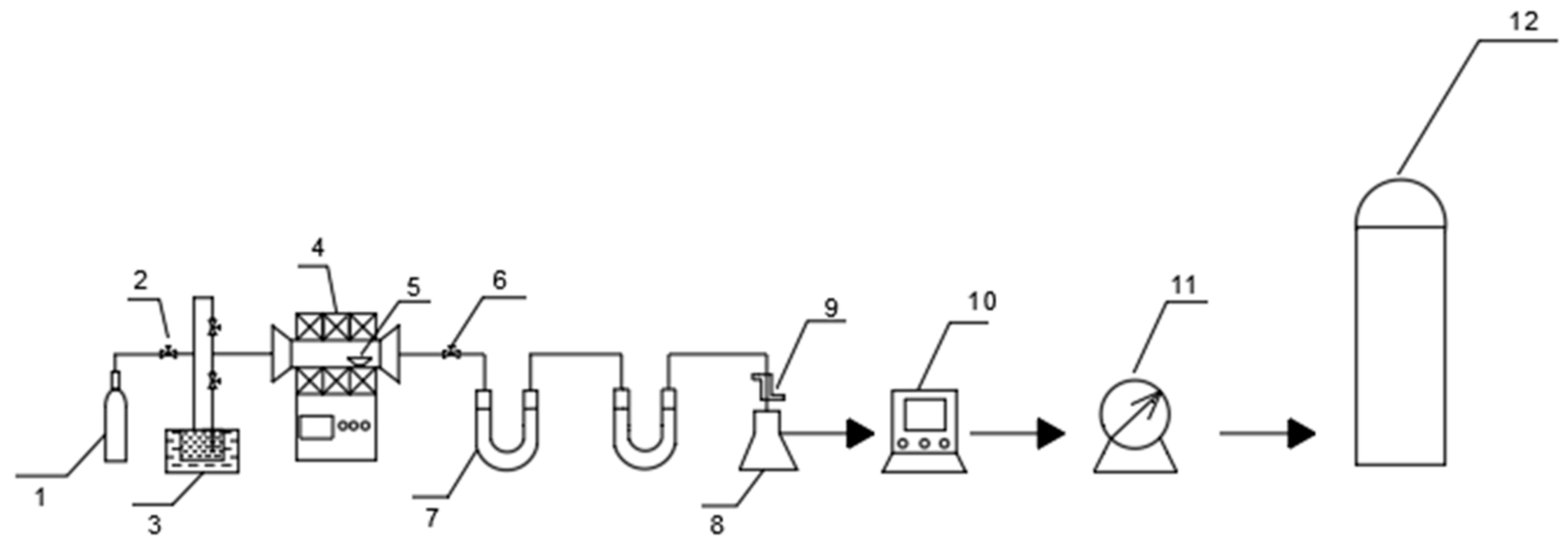
2.2. Basic Equipment
2.3. Scheme and Steps
3. Experimental Results and Discussion
3.1. In Situ Gasification of Cow Dung for Hydrogen Production
3.1.1. Optimum Experimental Parameters
- (1)
- Effect of gasification temperature on the gasification process of cow dung
- (2)
- Effect of water mass fraction on the gasification process
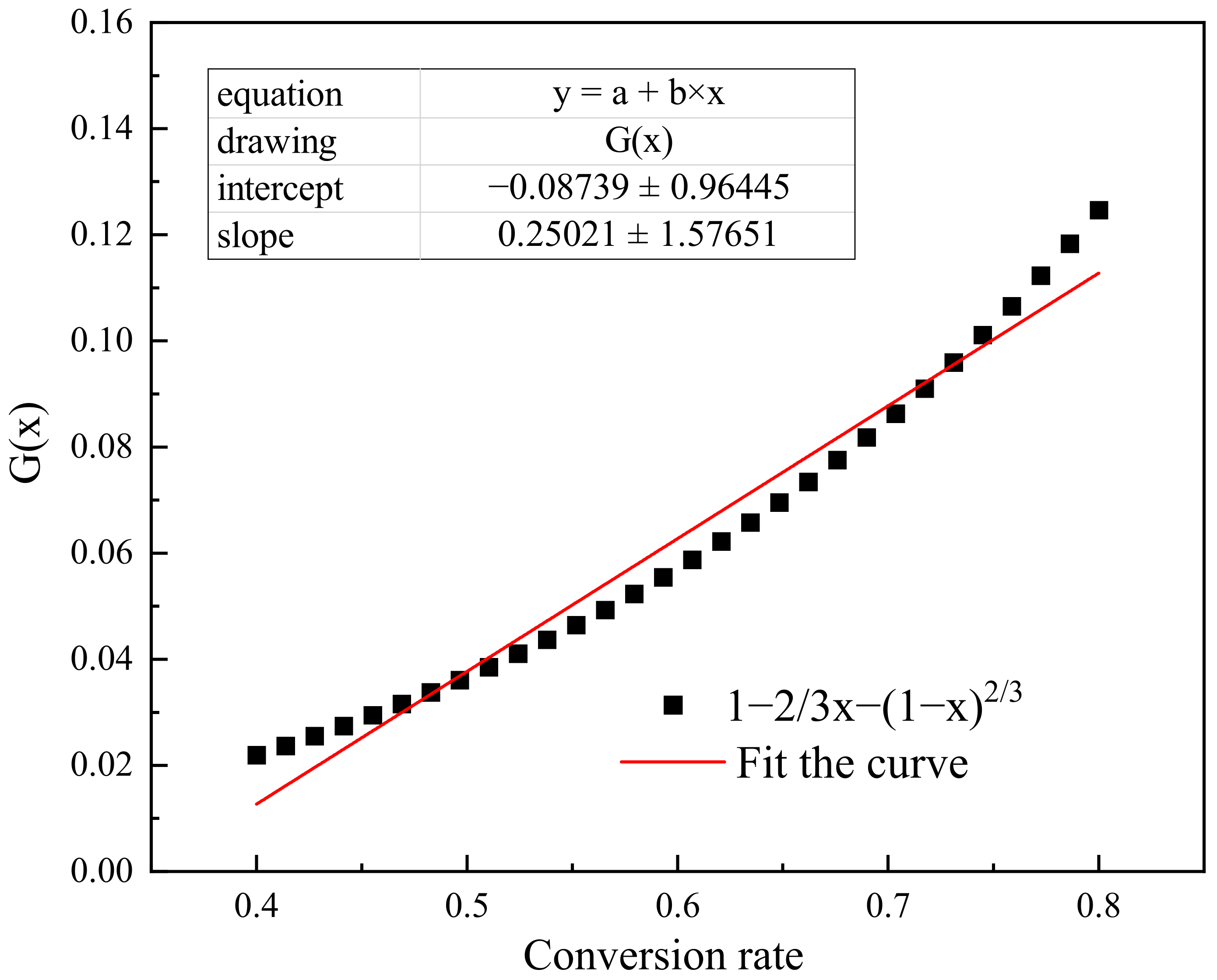
3.1.2. Mechanistic Analysis of In Situ Gasification
3.2. Hydrogen Production from Semi-Coke Gasification of Cow Dung
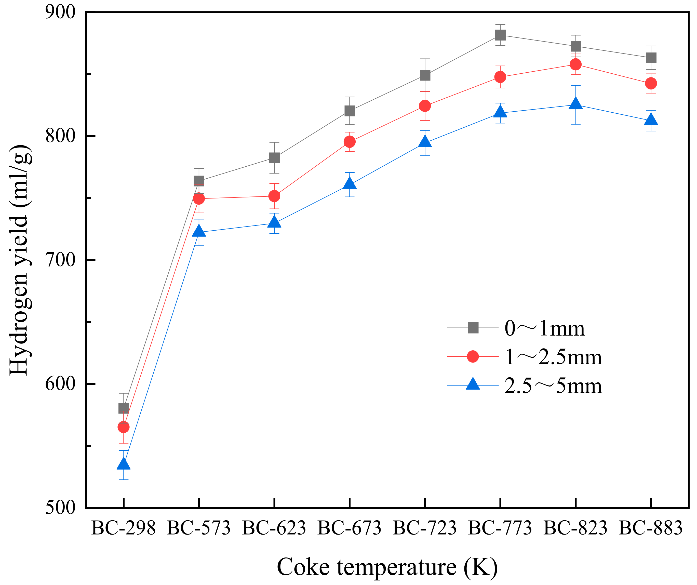
3.2.1. Hydrogen Yield from Semi-Coke Gasification
3.2.2. Mechanism of Hydrogen Production by Gasification of Cow Dung
4. Conclusions
- (1)
- The optimum process parameters for in situ gasification of cow manure are: gasification temperature 1173 K, water mass fraction 80%, heating rate 5 K/min, and feed temperature 673 K. The main factors affecting the hydrogen yield are gasification temperature and water mass fraction, and the hydrogen yield from in-situ gasification of cow manure is:
- (2)
- The high temperature and small particle size of the semi-coke cow dung preparation facilitates the gasification reaction and increases the hydrogen yield. The hydrogen yield φ2 prepared by semi-coke gasification is:
- (3)
- The semi-coking treatment separates the pyrolysis of cow dung from the water vapor gasification. This reduces the inhibition of the gasification reaction by volatile substances, improves the reaction conditions for the secondary cracking and reforming reactions, and increases the coke content in the cow dung. These effects are conducive to the water vapor gasification reaction and increasing the hydrogen production.
Author Contributions
Funding
Institutional Review Board Statement
Data Availability Statement
Conflicts of Interest
References
- Chang, A.C.; Chang, H.F.; Lin, F.J.; Lin, K.H.; Chen, C.H. Biomass gasification for hydrogen production. Int. J. Hydrogen Energy 2011, 36, 14252–14260. [Google Scholar] [CrossRef]
- Gautam, G.; Adhikari, S.; Bhavnani, S. Estimation of biomass synthesis gas composition using equilibrium modeling. Energy Fuels 2010, 24, 2692–2698. [Google Scholar] [CrossRef]
- Samimi, F.; Marzoughi, T.; Rahimpour, M.R. Energy and exergy analysis and optimization of biomass gasification process for hydrogen production (based on air, steam and air/steam gasifying agents). Int. J. Hydrogen Energy 2020, 45, 33185–33197. [Google Scholar] [CrossRef]
- Yong, Y.S.; Rasid, R.A. Process simulation of hydrogen production through biomass gasification: Introduction of torrefaction pre-treatment. Int. J. Hydrogen Energy 2021. [Google Scholar] [CrossRef]
- Balu, E.; Lee, U.; Chung, J.N. High temperature steam gasification of woody biomass–a combined experimental and mathematical modeling approach. Int. J. Hydrogen Energy 2015, 40, 14104–14115. [Google Scholar] [CrossRef]
- Tian, T.; Li, Q.; He, R.; Tan, Z.; Zhang, Y. Effects of biochemical composition on hydrogen production by biomass gasification. Int. J. Hydrogen Energy 2017, 42, 19723–19732. [Google Scholar] [CrossRef]
- Corella, J.; Toledo, J.M.; Molina, G. Biomass gasification with pure steam in fluidized bed: 12 variables that affect the effectiveness of the biomass gasifier. Int. J. Oil Gas Coal Technol. 2008, 1, 194–207. [Google Scholar] [CrossRef]
- Xu, C.C.; Donald, J.; Byambajav, E.; Ohtsuka, Y. Recent advances in catalysts for hot-gas removal of tar and NH3 from biomass gasification. Fuel 2010, 89, 1784–1795. [Google Scholar] [CrossRef]
- Cohce, M.K.; Rosen, M.A.; Dincer, I. Efficiency evaluation of a biomass gasification-based hydrogen production. Int. J. Hydrogen Energy 2011, 36, 11388–11398. [Google Scholar] [CrossRef]
- Song, G.; Chen, L.; Xiao, J.; Shen, L. Exergy evaluation of biomass steam gasification via interconnected fluidized beds. Int. J. Energy Res. 2013, 37, 1743–1751. [Google Scholar] [CrossRef]
- Kırtay, E. Recent advances in production of hydrogen from biomass. Energy Convers. Manag. 2011, 52, 1778–1789. [Google Scholar] [CrossRef]
- Khorasani, R.; Khodaparasti, M.S.; Tavakoli, O. Hydrogen production from dairy wastewater using catalytic supercritical water gasification: Mechanism and reaction pathway. Int. J. Hydrogen Energy 2021, 46, 22368–22384. [Google Scholar] [CrossRef]
- Xin, Y.; Cao, H.; Yuan, Q.; Wang, D. Two-step gasification of cattle manure for hydrogen-rich gas production: Effect of biochar preparation temperature and gasification temperature. Waste Manag. 2017, 68, 618–625. [Google Scholar] [CrossRef]
- Wan, W.; Dai, Z.; Li, C.; Yu, G.; Wang, F. Innovative concept for gasification for hydrogen based on the heat integration between water gas shift unit and coal-water-slurry gasification unit. Int. J. Hydrogen Energy 2014, 39, 7811–7818. [Google Scholar] [CrossRef]
- Straka, P.; Bičáková, O. Hydrogen-rich gas as a product of two-stage co-gasification of lignite/waste plastics mixtures. Int. J. Hydrogen Energy 2014, 39, 10987–10995. [Google Scholar] [CrossRef]
- Yu, L.; Zhang, R.; Cao, C.; Liu, L.; Fang, J.; Jin, H. Hydrogen production from supercritical water gasification of lignin catalyzed by Ni supported on various zeolites. Fuel 2022, 319, 123744. [Google Scholar] [CrossRef]
- Burnham, A.K.; Braun, R.L. Global kinetic analysis of complex materials. Energy Fuels 1999, 13, 1–22. [Google Scholar] [CrossRef]
- Alonso, M.; Alvarez, D.; Borrego, A.; Menédez, R.; Marban, G. Systematic effects of coal rank and type on the kinetic of coal pyrolysis. Energy Fuels 2001, 15, 413–428. [Google Scholar] [CrossRef]
- Mao, Y.; Dong, L.; Dong, Y.; Liu, W.; Chang, J.; Yang, S.; Lv, Z.; Fan, P. Fast co-pyrolysis of biomass and lignite in a micro fluidized bed reactor analyzer. Bioresour. Technol. 2015, 181, 155–162. [Google Scholar] [CrossRef]
- Moghtaderi, B. Effects of controlling parameters on production of hydrogen by catalytic steam gasification of biomass at low temperatures. Fuel 2007, 86, 2422–2430. [Google Scholar] [CrossRef]
- Hao, X.; Guo, L.; Zhang, X.; Guan, Y. Hydrogen production from catalytic gasification of cellulose in supercritical water. Chem. Eng. J. 2005, 110, 57–65. [Google Scholar] [CrossRef]
- Zhang, R.; Cummer, K.; Suby, A.; Brown, R.C. Biomass-derived hydrogen from an air-blown gasifier. Fuel Process. Technol. 2005, 86, 861–874. [Google Scholar] [CrossRef]
- Homma, S.; Ogata, S.; Koga, J.; Matsumoto, S. Gas–solid reaction model for a shrinking spherical particle with unreacted shrinking core. Chem. Eng. Sci. 2005, 60, 4971–4980. [Google Scholar] [CrossRef]
- Kawamata, Y.; Yoshikawa, T.; Aoki, H.; Koyama, Y.; Nakasaka, Y.; Yoshida, M.; Masuda, T. Kinetic analysis of delignification of cedar wood during organosolv treatment with a two-phase solvent using the unreacted-core model. Chem. Eng. J. 2019, 368, 71–78. [Google Scholar] [CrossRef]


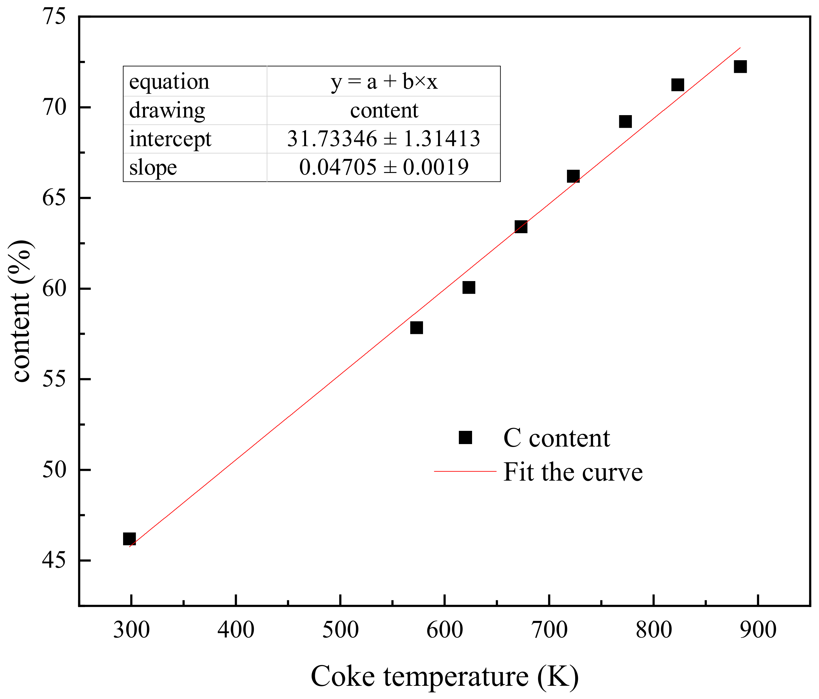
| Sample | Elemental Analysis (%) | Proximate Analysis (%) | ||||||
|---|---|---|---|---|---|---|---|---|
| C | H | O | N | S | V | FC | A | |
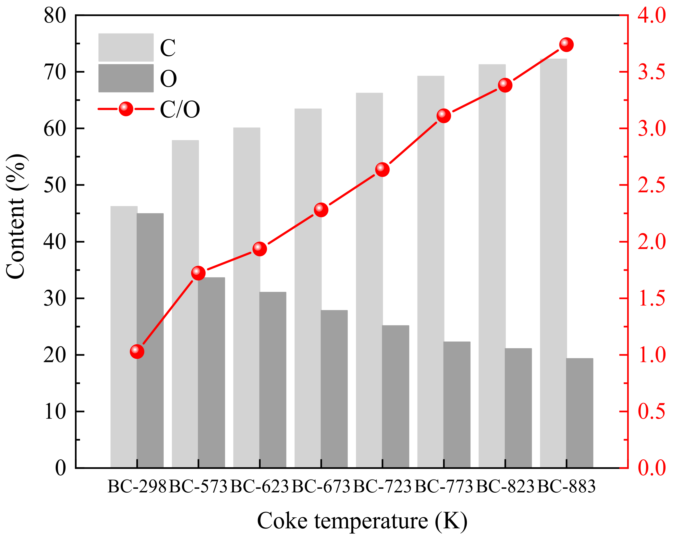
| BC-298 | 46.21 | 5.44 | 44.94 | 2.39 | 1.02 | 64.13 | 18.23 | 17.64 |
| BC-573 | 57.85 | 5.12 | 33.62 | 2.82 | 0.59 | 49.25 | 24.51 | 26.24 |
| BC-623 | 60.07 | 5.15 | 31.04 | 3.01 | 0.63 | 45.63 | 26.29 | 28.08 |
| BC-673 | 63.42 | 5.21 | 27.82 | 3.1 | 0.45 | 39.54 | 29.84 | 30.62 |
| BC-723 | 66.21 | 5.17 | 25.12 | 3.07 | 0.43 | 35.29 | 32.43 | 32.28 |
| BC-773 | 69.22 | 5.13 | 22.25 | 3.05 | 0.35 | 31.54 | 34.51 | 33.95 |
| BC-823 | 71.25 | 5.12 | 21.07 | 2.96 | 0.40 | 27.37 | 38.02 | 34.61 |
| BC-873 | 72.25 | 5.12 | 19.32 | 2.91 | 0.45 | 23.54 | 40.15 | 36.31 |
| A | B | C | D | ||||||||||||
|---|---|---|---|---|---|---|---|---|---|---|---|---|---|---|---|
| Temperature (K) | Water Mass Fraction (%) | Heating Rate (K·min−1) | Feed Temperature (K) | ||||||||||||
| A1 | A2 | A3 | A4 | B1 | B2 | B3 | B4 | C1 | C2 | C3 | C4 | D1 | D2 | D3 | D4 |
| 873 | 973 | 1073 | 1173 | 50 | 60 | 70 | 80 | 5 | 10 | 15 | 20 | 673 | 723 | 773 | 823 |
| No. | Temperature (K) | Water Mass Fraction (%) | Heating Rate (K·min−1) | Feed Temperature (K) | Hydrogen Yield (mL·g−1) |
|---|---|---|---|---|---|
| 1 | 873 | 50 | 5 | 673 | 80.56 |
| 2 | 873 | 60 | 10 | 723 | 87.87 |
| 3 | 873 | 70 | 15 | 773 | 95.46 |
| 4 | 873 | 80 | 20 | 823 | 107.95 |
| 5 | 973 | 50 | 10 | 773 | 116.61 |
| 6 | 973 | 60 | 5 | 823 | 127.89 |
| 7 | 973 | 70 | 20 | 673 | 157.68 |
| 8 | 973 | 80 | 15 | 723 | 182.43 |
| 9 | 1073 | 50 | 15 | 823 | 343.14 |
| 10 | 1073 | 60 | 20 | 773 | 354.57 |
| 11 | 1073 | 70 | 5 | 723 | 389.66 |
| 12 | 1073 | 80 | 10 | 673 | 420.95 |
| 13 | 1173 | 50 | 20 | 723 | 476.24 |
| 14 | 1173 | 60 | 15 | 673 | 504.54 |
| 15 | 1173 | 70 | 10 | 823 | 530.34 |
| 16 | 1173 | 80 | 5 | 773 | 573.51 |
| Factor | Indicators | A | B | C | D |
|---|---|---|---|---|---|
| Hydrogen yield (mL·g−1) | K1 | 371.84 | 1017.55 | 1163.73 | 1171.62 |
| K2 | 584.61 | 1074.87 | 1131.20 | 1155.77 | |
| K3 | 1509.32 | 1173.14 | 1141.15 | 1126.57 | |
| K4 | 2084.63 | 1284.84 | 1111.32 | 1096.44 | |
| k1 | 92.96 | 254.39 | 290.94 | 292.01 | |
| k2 | 146.15 | 268.72 | 284.05 | 288.94 | |
| k3 | 377.33 | 293.29 | 285.04 | 281.64 | |
| k4 | 521.16 | 321.21 | 277.58 | 274.11 | |
| R | 428.2 | 66.82 | 13.36 | 17.9 | |
| Primary and Secondary Factors: ABDC | |||||
| Optimization Scheme: A4B4D1C1 | |||||
| No. | Coke Temperature (K) | Particle Diameter (mm) | Hydrogen Yield (mL·g−1) |
|---|---|---|---|
| 1 | BC-298 | 0~1 | 580.45 |
| 2 | BC-298 | 1~2.5 | 565.24 |
| 3 | BC-298 | 2.5~5 | 534.51 |
| 4 | BC-573 | 0~1 | 763.82 |
| 5 | BC-573 | 1~2.5 | 749.58 |
| 6 | BC-573 | 2.5~5 | 722.42 |
| 7 | BC-623 | 0~1 | 782.46 |
| 8 | BC-623 | 1~2.5 | 751.56 |
| 9 | BC-623 | 2.5~5 | 729.64 |
| 10 | BC-673 | 0~1 | 820.39 |
| 11 | BC-673 | 1~2.5 | 795.45 |
| 12 | BC-673 | 2.5~5 | 760.83 |
| 13 | BC-723 | 0~1 | 849.13 |
| 14 | BC-723 | 1~2.5 | 824.35 |
| 15 | BC-723 | 2.5~5 | 794.51 |
| 16 | BC-773 | 0~1 | 881.54 |
| 17 | BC-773 | 1~2.5 | 847.76 |
| 18 | BC-773 | 2.5~5 | 818.59 |
| 19 | BC-823 | 0~1 | 872.65 |
| 20 | BC-823 | 1~2.5 | 857.94 |
| 21 | BC-823 | 2.5~5 | 825.26 |
| 22 | BC-873 | 0~1 | 863.24 |
| 23 | BC-873 | 1~2.5 | 842.51 |
| 24 | BC-873 | 2.5~5 | 812.45 |
Publisher’s Note: MDPI stays neutral with regard to jurisdictional claims in published maps and institutional affiliations. |
© 2022 by the authors. Licensee MDPI, Basel, Switzerland. This article is an open access article distributed under the terms and conditions of the Creative Commons Attribution (CC BY) license (https://creativecommons.org/licenses/by/4.0/).
Share and Cite
Zhu, G.; Huang, J.; Wan, Z.; Ling, H.; Xu, Q. Cow Dung Gasification Process for Hydrogen Production Using Water Vapor as Gasification Agent. Processes 2022, 10, 1257. https://doi.org/10.3390/pr10071257
Zhu G, Huang J, Wan Z, Ling H, Xu Q. Cow Dung Gasification Process for Hydrogen Production Using Water Vapor as Gasification Agent. Processes. 2022; 10(7):1257. https://doi.org/10.3390/pr10071257
Chicago/Turabian StyleZhu, Guomin, Jinyu Huang, Ziwei Wan, Haitao Ling, and Qiyan Xu. 2022. "Cow Dung Gasification Process for Hydrogen Production Using Water Vapor as Gasification Agent" Processes 10, no. 7: 1257. https://doi.org/10.3390/pr10071257
APA StyleZhu, G., Huang, J., Wan, Z., Ling, H., & Xu, Q. (2022). Cow Dung Gasification Process for Hydrogen Production Using Water Vapor as Gasification Agent. Processes, 10(7), 1257. https://doi.org/10.3390/pr10071257