Article

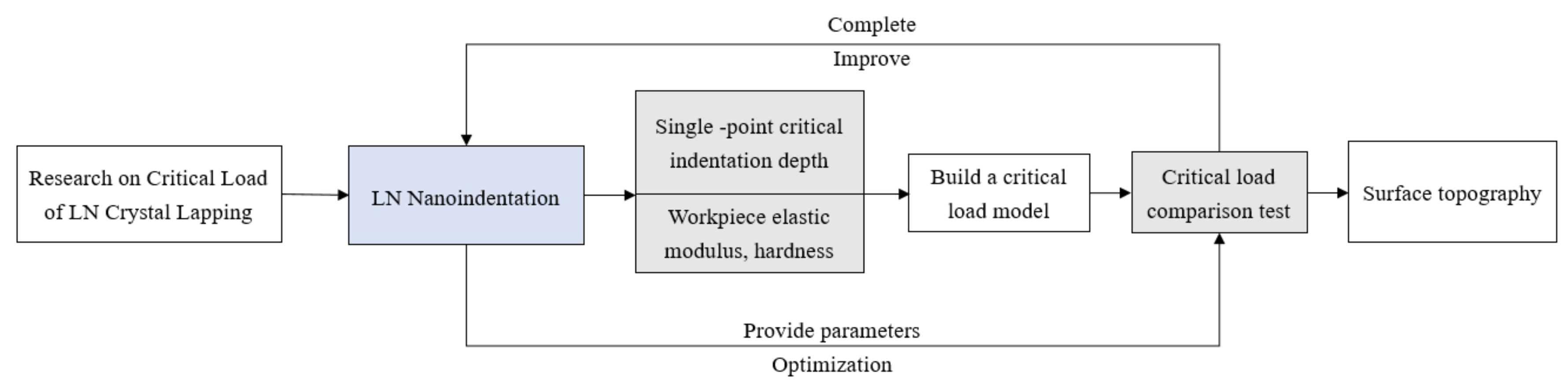
Research on Critical Load of Lithium Niobate Crystal Lapping

1
School of Mechanical Engineering, Zhejiang University of Technology, Hangzhou 310023, China
2
Zhejiang Provincial Key Laboratory of Ministry of Education, Hangzhou 310023, China
*
Author to whom correspondence should be addressed.
Processes 2022, 10(5), 912; https://doi.org/10.3390/pr10050912
Submission received: 20 March 2022 / Revised: 30 April 2022 / Accepted: 2 May 2022 / Published: 5 May 2022

Abstract

:
The elastic modulus and hardness of lithium niobate crystals were obtained by nanoindentation technology, and critical load and critical indentation depth range were determined by AFM by indentation morphology under different loads. According to the normal distribution characteristics of abrasive grains, the critical load model of lapping was deduced, and the critical load of lithium niobate during lapping process under different grain sizes was obtained. It was verified using a single-factor experiment in which experimental results were consistent with theoretical research.

1. Introduction

In recent years, with the development of microelectronics technology and microsystems, soft and brittle materials have been widely used in optics, communication, display, and other fields, due to their unique characteristics [1,2,3,4,5,6,7]. With its wider application in the industrial field, the requirements in terms of surface damage are becoming higher and higher. Lithium niobate (LiNbO3, LN) is a typical soft and brittle material. LN crystal material has special piezoelectric, electro-optic, nonlinear, photorefractive, pyroelectric, and other properties and is widely applied in surface filters, micro-acoustic devices, optical waveguide substrates, laser modulators, optical isolators, and other industries [8,9,10,11,12,13]. Traditional lapping, lapping, and mechanical polishing generates defects in machined LN specimens, such as scratches and free imbedded abrasives. This shows that LN is a material that is difficult to machine. Nevertheless, ultrasmooth and damage-free wafers of LN are stringently required for use in high-performance photonic devices. Lapping is an essential part in the processing of lithium niobate. In order to ensure lapping efficiency and obtain high-quality lithium niobate surface, this paper analyzes the material properties of Y-cut lithium niobate crystal and the critical load in lapping and establishes the critical load model [14,15,16,17,18].
Various studies have been carried out on LN and the critical loads of lapping. Sumeet Bhagavat et al. [19] used nanoindentation technology to study the anisotropy of lithium niobate crystals, and the proposed lithium niobate displays a pop-in phenomenon, though the pop-in load and number of pop-ins vary with crystallographic orientation of the indenter. Xu et al. [20] studied the normal distribution in diamond lapping processes, finding that the critical lapping pressure is related to the distance between workpieces, the size of abrasive particles, the total number of abrasive particles, and the hardness of workpieces and lapping disks. Pan [21] carried out nanoindentation test on a single crystal 6H-SiC to obtain single-point critical loads and determined that optimal loads through experiments in the lapping stage of free abrasive. Yuan et al. [22] used consolidated abrasive lapping discs to process soft and brittle lithium tantalate, obtained the properties of lithium tantalate material through nanoindentation, and studied the influence of parameters on processing with an orthogonal experiment; Zhu [23] used consolidation lapping on LN crystals, finding that the depths of surface-damaging layers decreased by 40% after the pressure decreased by 50%. Because of the special characteristics of LN, it is necessary to control the lapping pressure in the machining.
In the above research on lithium niobate and the critical load of lapping, some scholars analyzed some material properties of lithium niobate and the pop-in phenomenon in lapping. The critical load is obtained by machining a diamond with free abrasive. Lithium niobate is processed with a consolidated abrasive [24]. However, no one has considered the direction of the lapping lithium niobate with a free abrasive. The processing method using a free abrasive is the simplest and common lapping method. In this study, we used nanoindentation technology to analyze the material properties of Y-cut lithium niobate, obtained the depth under different loads, analyzed the pop-in phenomenon, determined the single-point critical load and indentation depth, and established a critical load-model in the lapping process. Finally, the feasibility of the critical load model was verified experimentally, providing a basis for the selection of load in the lapping process of lithium niobate crystal.

2. Materials and Methods

2.1. Nanoindentation Experiment of LN Crystal

LN crystals have special mechanical properties. In order to study the lapping of lithium niobate crystals, it is necessary to know the material characteristics and the critical loads [25] for brittle–plastic transition. The elastic modulus and hardness of LN crystals were determined by low-load and high-load modes, and the material parameters of LN were provided for the subsequent critical load formula. At the same time, the single-point critical load ranges and the single-point critical-indentation depth range of fracture were obtained. The reason for using the nanoindentation experiment is that the damage generated in the indented state is larger than that of scratches, which is caused by the indenter of the nanoindenter. If the critical load in the indented state can be guaranteed, the surface quality obtained can be guaranteed to the greatest extent in the actual machining process. The test flow of the full text is shown in Figure 1.

2.1.1. Test Specimen

The Y-cut is the most easily processed crystal direction of lithium niobate crystals [26,27,28,29,30]. According to the actual requirements in industrial production, this kind of crystal direction wafer was selected in the experiments, and the polished wafers produced by CLP Deqing Huaying Electronics Co. Ltd. Hangzhou, China were used, with a diameter of 3 inches and a thickness of 0.5 mm, as shown in Figure 2.
A TI980 nanoindenter of Hysitron Company was selected, and a standard Berkovich indenter was used. The half angle of the indenter was 65.27, the included angle was 142.30, the Young’s modulus was 1140 GPa, and the Poisson’s ratio was 0.07. Displacement is used as a control signal to control the loading process. The test is divided into the loading, load-keeping, and unloading processes, and the times are 5 s, 2 s, and 5 s, respectively.

2.1.2. LN Loading Procedure

At the low-load stage, the LN crystal of Y-cut was made into a sample, which was placed on a glass slide and fixed on a stage after the binder was dried, and the middle area of the sample was selected as a test area. The loading loads were 300 μN, 500 μN, 1000 μN, 5000 μN, 8000 μN, and 10,000 μN. Three test points were tested repeatedly for each load, totaling eighteen points. The indentation details were obtained by in situ scanning, with a distance of 5 mm, so as to prevent the test points from influencing each other and to obtain the elastic modulus and hardness of lithium niobate crystals.
A high-load stage: The material pretreatment stage was the same as the low load, and the loading loads were 11 mN, 13 mN, 15 mN, 20 mN, and 30 mN. A single-load test comprising 3 test points were made through indentation crack generation, making a total of 15 points; these test points determined the critical loads of lithium niobate Y-cut through the Gwyddion to obtain the critical indentation depth range.

2.2. Critical Loads of Lapping

To obtain the critical loads and pressures of the workpieces in a lapping process, it is necessary to study the total number of abrasive particles and the distribution of abrasive particles in the lapping process.

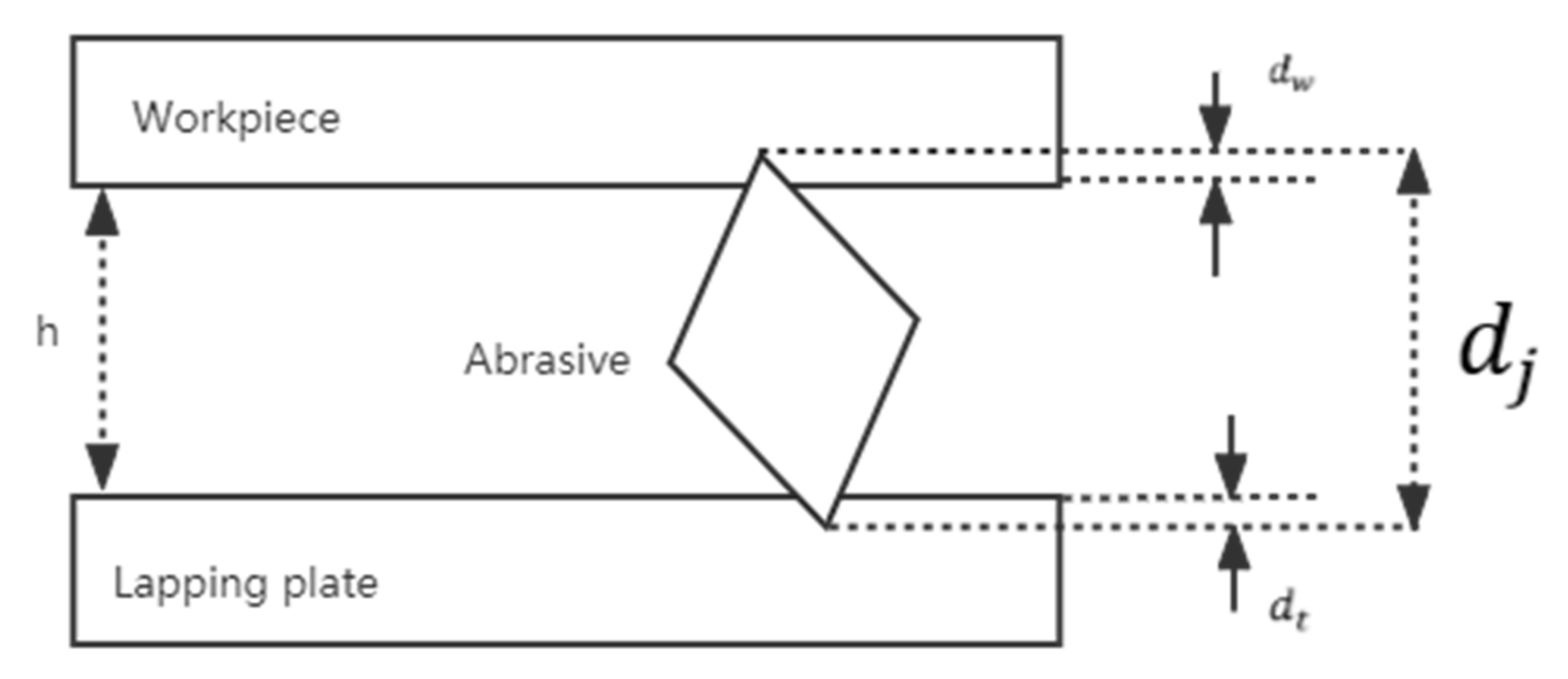
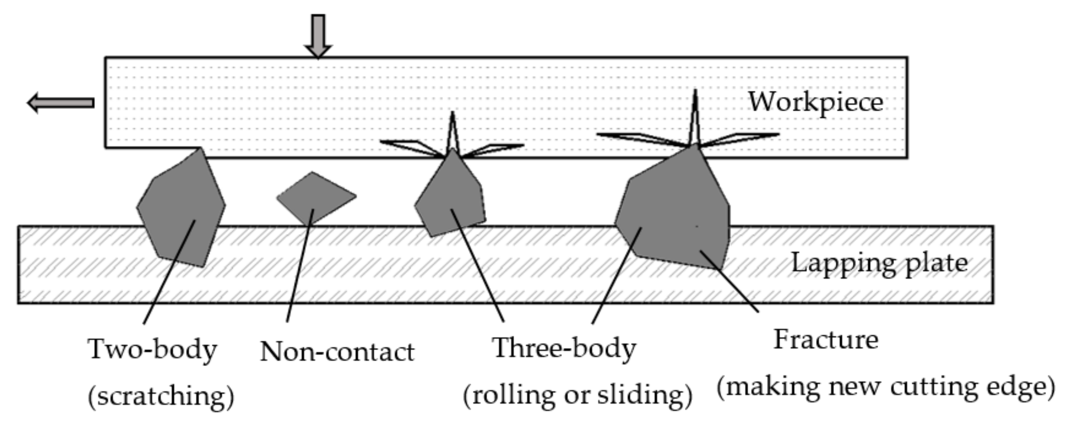
2.2.1. Distribution of Abrasive Particles

The lapping process mainly relies on the scratching between a free abrasive and a workpiece surface under the loads, as shown in Figure 3. At the same time, because the lithium niobate crystal is soft and brittle, it will cause great damage to the crystal under high loads.
In the solid–liquid two-phase state, not all free abrasive particles are involved in the material removal process, and some abrasive particles cannot even contact the workpiece surface, which is due to the normal distribution of abrasive particles.
The probability density function f(x) of normal distribution is as follows
f x = 1 2 π σ exp x μ 2 2 σ 2
where μ is the average value of distribution, which represents the height of abrasive particles in this research, and σ is the standard deviation. The alumina abrasive particles used in the experiment are distributed normally, and the distribution parameters are shown in Table 1.

2.2.2. Formula for Solving Critical Loads

By analyzing the pressure of a single abrasive particle in the actual lapping process, the critical pressure of a whole workpiece is shown to be the sum of the stress states of all abrasive particles. The actual stress state in the lapping process is shown in Figure 4. With the action of loads, the stress relationship among the workpiece, abrasive particles, and lapping disk dj is the vertical height of abrasive particles, dw the depths of abrasive particles entering workpiece, and dt the depths of abrasive particles embedded in the lapping disk, Km, Kw, Kt which represent the abrasive particle hardness, workpiece hardness, and lapping hardness, respectively. For abrasive particles whose vertical height dj exceeds the height h, the deformation of abrasive particles, workpiece, and abrasive disc is equal to the action of loads and pressure, so the distance h between workpiece and abrasive disc can be expressed as
h = d j F i K m F i K w F i K t
Because the materials of workpiece, abrasive grains, and abrasive disc are lithium niobate, alumina, and cast iron, respectively, and the Mohs hardness is 5, 9, and 7, respectively, the hardness of abrasive grains is quite different from that of workpiece and abrasive disc, so the deformation of abrasive grain and abrasive disc under loads is ignored in the lapping process, and only the deformation of workpiece is considered:
h = d j F i K w
When the abrasive grain di is larger than h, the workpiece is in an effective lapping state. When the abrasive grain di is smaller than h, there is no contact between the abrasive grain and the workpiece, and the acting force is 0. Therefore, the whole acting force formula can be expressed as
F i = ( d i h ) · K w   d i > h F i = 0   d i h
The particle size distribution function fdi accords with normal distribution. In the lapping area of the workpiece, the distance h between the workpiece and the lapping disk is fixed, and the resultant force is the sum of all Fi, which can be expressed in integral form.
F = N 2 π σ K w h exp [ d i μ 2 2 σ 2 ] d d i
Equation (5) cannot be solved directly but can be expressed as an approximate function
g x = a · exp a x μ 1 + exp a x μ 2
where a = 42, the corresponding distribution function is
G x = exp a x μ 1 + exp a x μ
σ 2 2 π σ exp d w 2 2 σ 2 + d w 1 + exp a · d w = F N · K w
The definite integral of normal distribution can be obtained by Equation (7), which is transformed into
σ 2 2 π σ exp d w 2 2 σ 2 = F N · K w
In the formula, F: critical load, dw: critical indentation depth, Kw: lithium niobate hardness, N: total number of abrasive grains, and σ: standard deviation of abrasive grain size.

2.3. Test Validation

The W7 granularity alumina abrasive was selected, the concentration of lapping fluid was 20%, the lapping time was 30 min, the rotating speed of lapping disc was 20 r/min, and the flow rate of the lapping fluid was 50 mL/min. After the experiment, the samples were washed with clear water first and then washed with ethanol and pure water in a ultrasonic cleaning machine for 2 min, respectively. The lapping parameters of lithium niobate are shown in Table 2.

3. Results and Analysis

3.1. Analysis of the Nanoindentation Experiment on the Lithium Niobate Crystal

The loading–displacement relationship of lithium niobate crystals under low loads is shown in Figure 5. The curve of the sixth Y-cut is smooth as a whole, and the slope of the unloading curve is consistent.
In the loading stage, with the increasing of indenter loads, the depths of indenters into material also increases, which is reflected in the increase in displacement. In the process of indentation, not only plastic deformation but also elastic deformation occurs in the tested sample, so there is a nonlinear relationship between indentation depths, that is, displacement and pressure.
In the condition of low loads, the indentation under different loads was scanned in situ [31,32,33], with a range of 5 μm × 5 μm. As shown in Figure 6, under the load of 300–8000 μN, an AFM image of the nanoindentation was observed. There was no crack near the indentation. The nanoindentation caused plastic deformation of the LN crystal, but it was also found that the load–displacement curve under the load of 10,000 μN was not smooth, the AFM image was slight, so it was judged that a slight crack was generated on the surface under a load of 10,000 μN.
The indentation depth was 0.09 μm at 8 mN and 0.105 μm at 10 mN, as shown in Figure 7. In order to study the critical pressure and indentation depths of brittle plastic deformation of lithium niobate crystals, high load nanoindentation was used for experiments.
In the period of low loads, through 3 × 6 experiments with a total of 18 points, several loading process were carried out with the same loading, load keeping, and unloading. As shown in Figure 8 and Figure 9, specific data scatter plots of elastic modulus and hardness were obtained. The critical load model requires accurate data on the elastic modulus and hardness of lithium niobate, so the data obtained from the nanoindentation experiments were processed and averaged. Among them, the standard deviation of elastic modulus data was 3.59 GPa, and the deviation rate is 1.98%; the standard deviation of hardness data was 0.25 GPa, and the deviation rate is 2.93%. The elastic modulus and hardness of Y-cut lithium niobate crystal were 180.61 GPa and 8.495 GPa, respectively.
The lithium niobate crystals were loaded under high loads, and the fracture of lithium niobate was further confirmed by in situ scanning. First, indentation experiments under 20 mN and 30 mN loads were carried out, and the surface cracks were obvious, as shown in Figure 10a,b.
As shown in Figure 11, in a 15 mN load test, the tip crack was not obvious, but there were signs of cracking. When the load was further reduced to 11 mN and 13 mN, slight cracks occurred at 11 mN, so the critical loads of lithium niobate could be determined to be 10–20 mN. In order to further confirm the brittle–plastic transition, the 13 mN load–displacement curve was sorted by origin as shown in Figure 12, and it was found that the pop-in point was the same as the observed situation, which could prove that the indentation had undergone the brittle–plastic transition.
Gwyddion software was also used to scan the indentation under high loads in situ, as shown in Figure 13, and the critical indentation depths ranged from 0.105 μm to 0.16 μm.
Indentation-induced cracks can be affected by material properties, the test environment, indenter shapes and loads. The end of the Vickers indenter used in the test was a triangular pyramid, and the included angle between the two edges and two opposite faces were 65.27 half angle and 142.30 angle. There were a large number of dislocations in the crystal structures of lithium niobate, and the internal irregular arrangement led to the slippage of the internal grains of LN with the action of external force, resulting in the plastic deformation stage of lithium niobate. In a certain load range, LN crystals were in the plastic deformation zone. With the increase in loads, the stress exceeded the critical range, and the LN crystals would crack, as shown in Figure 10 and Figure 11 on the LN surface under high loads. In order to restrain this phenomenon during the processing of lithium niobate crystals, it is necessary to analyze the critical loads of lithium niobate lapping.

3.2. Critical Loads Solution Results

Critical load can be obtained by using the concentration of lapping fluid and the area of the working area. The total number of abrasive particles N, μ, and σ are all known values. See Table 1 for details. h can be converted into μ d w , and d w is the critical indentation depth of workpiece. In the formula, σ 2 2 π σ exp d w 2 2 σ 2 is much larger than d w 1 + exp a · d w , which is further simplified to
σ 2 2 π σ exp d w 2 2 σ 2 = F N · K w
Through a nanoindentation experiment, the critical indentation depth was found to be 0.105 μm and the hardness was 8.495 GPa. By substituting the above values into Formula (9), the critical loads of LN crystals with different abrasive particles can be obtained, as shown in Table 3.

3.3. Analysis of the Validation of the Tests

Table 3 lists the corresponding parameters of several commonly used alumina abrasive grains. In the test verification, we chose alumina abrasive grains with a W7 grain size. The surface of LN crystal was observed using VHX-S650E. As shown in Figure 14, with the load of 15 N and 20 N, there were no obvious scratches and no abrasive particles embedded on the surface of the samples. Therefore, the visible damage to LN surface is not caused during machining with a load of 20 N or less.
The test results under the loads of 25 N, 35 N, and 40 N are shown in Figure 15. It can be seen from the figure that obvious scratches have been produced on the machined surface with loads of 25 N and 35 N, and an obvious fracture phenomenon appeared on the surface of LN crystal under the load of 40 N, as shown in Figure 15c. The reason for this result is that under the pressure exceeding the critical load value, the removal of abrasive particles and the workpiece during the lapping process can cause cracks or even chipping on the surface of the workpiece, and such damage aggregation will produce surface scratches. After the load continues to increase, it can be found in Figure 15 that the degree of damage of the lapping surface of the workpiece is increasing, which indicates the width of the scratch and the cracks and breakage on both sides of the scratch.
It can be seen from the experimental results that when the alumina abrasive grains with a W7 grain size are used and the corresponding critical load is taken, the lithium niobate lapping process can obtain a good surface, as shown in Figure 14. This proves that the critical load model is correct.

4. Conclusions

(1)
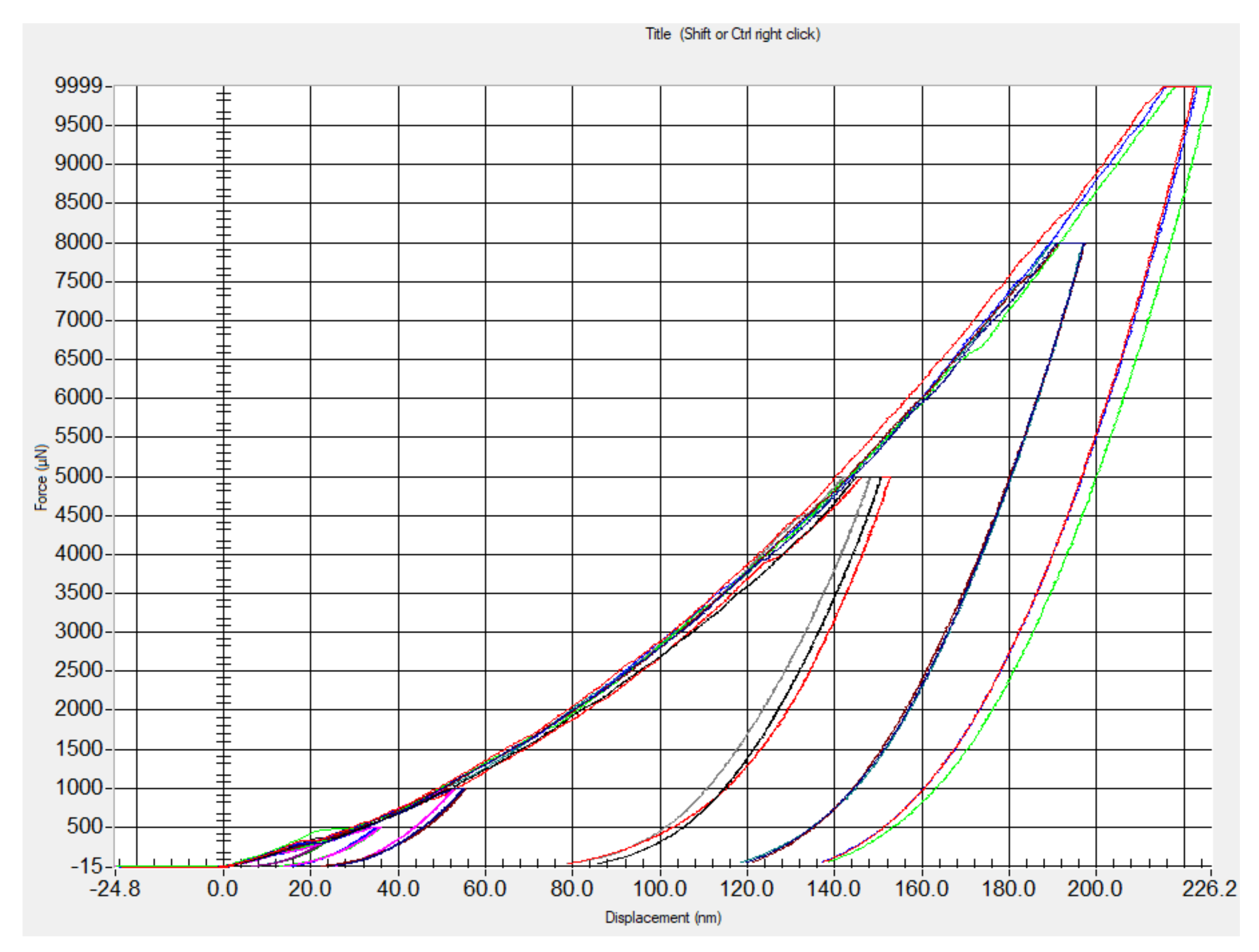
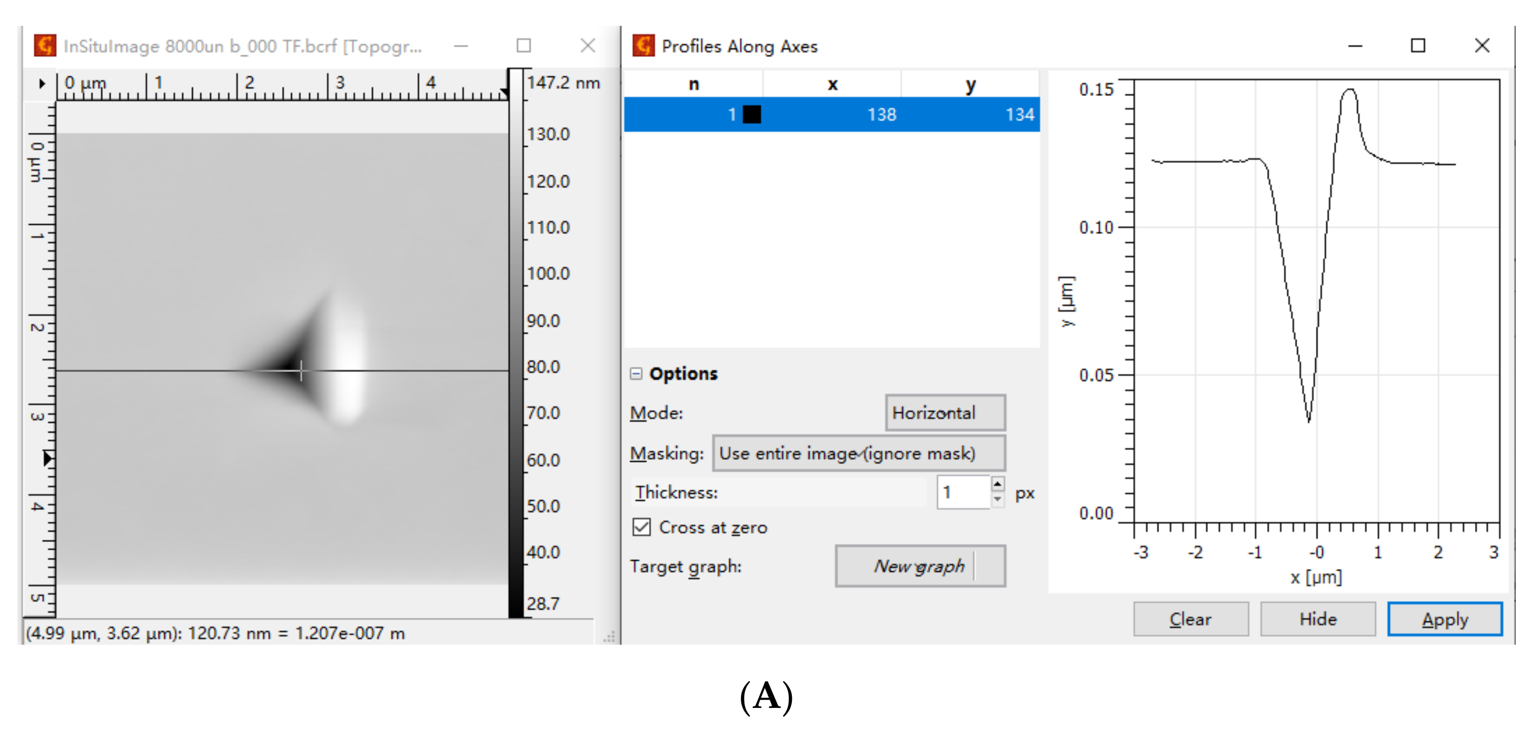
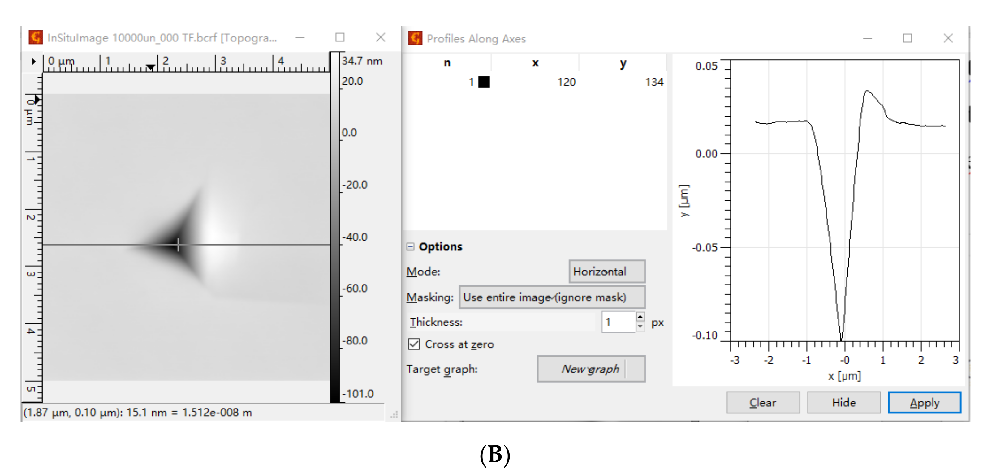
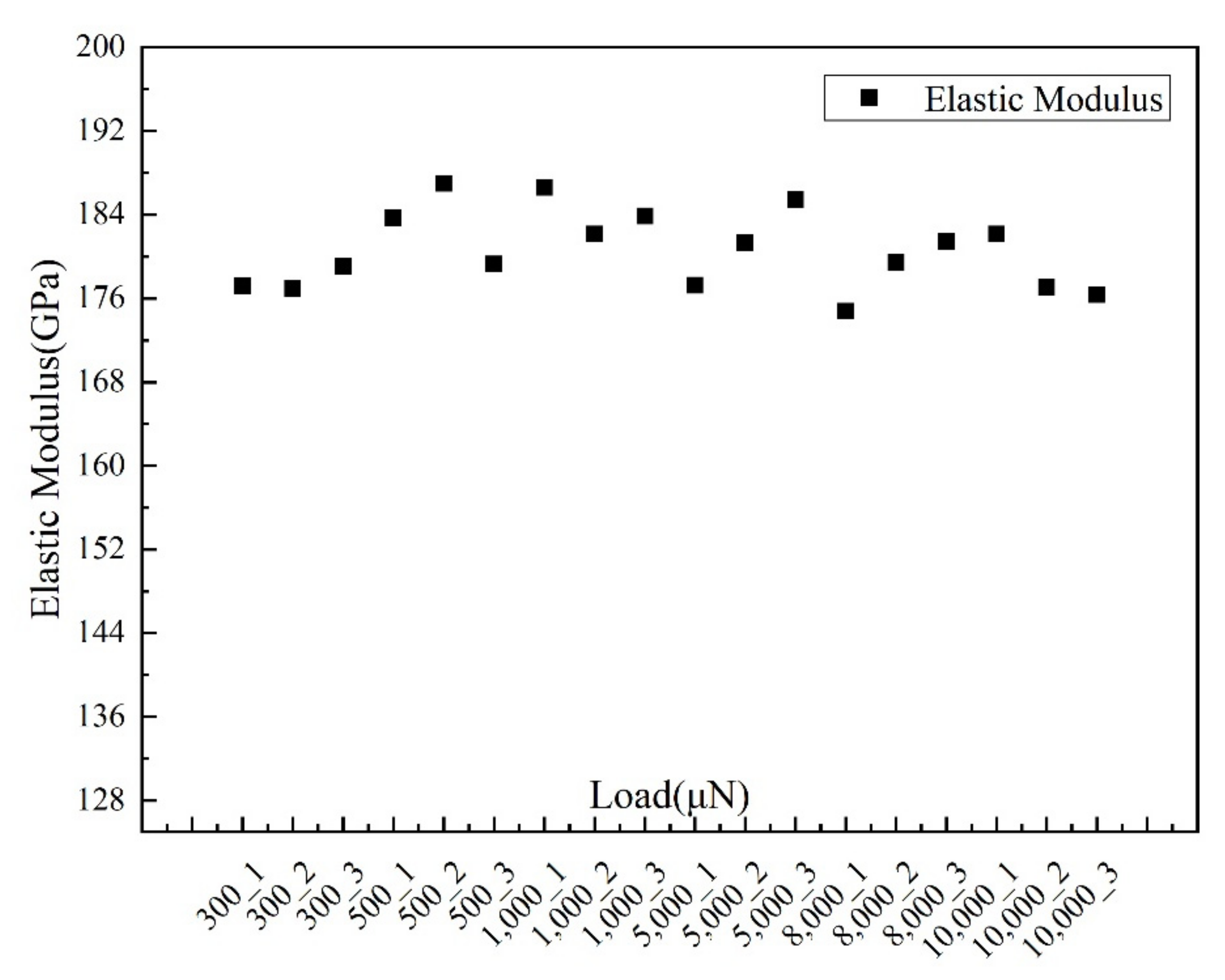
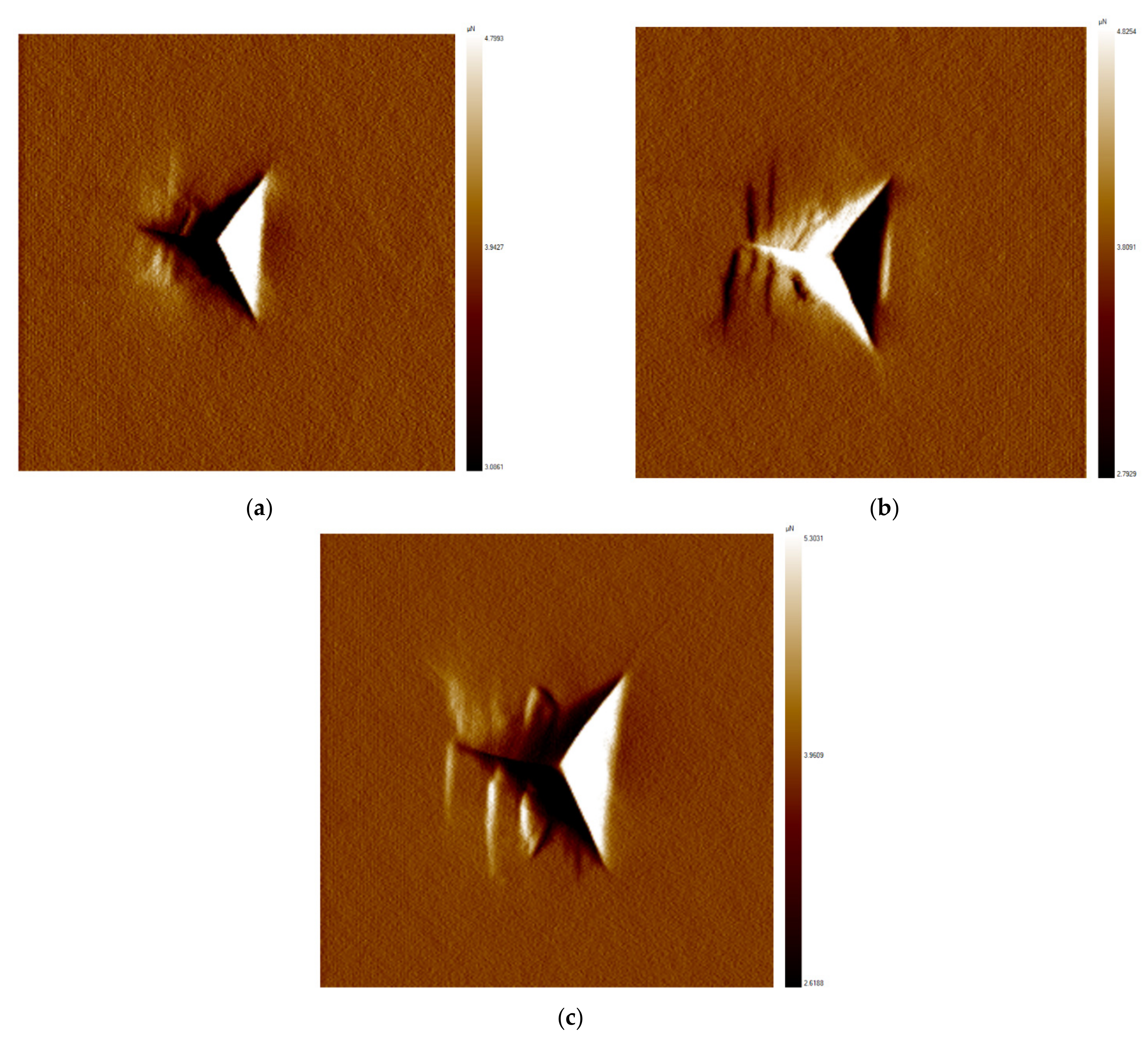
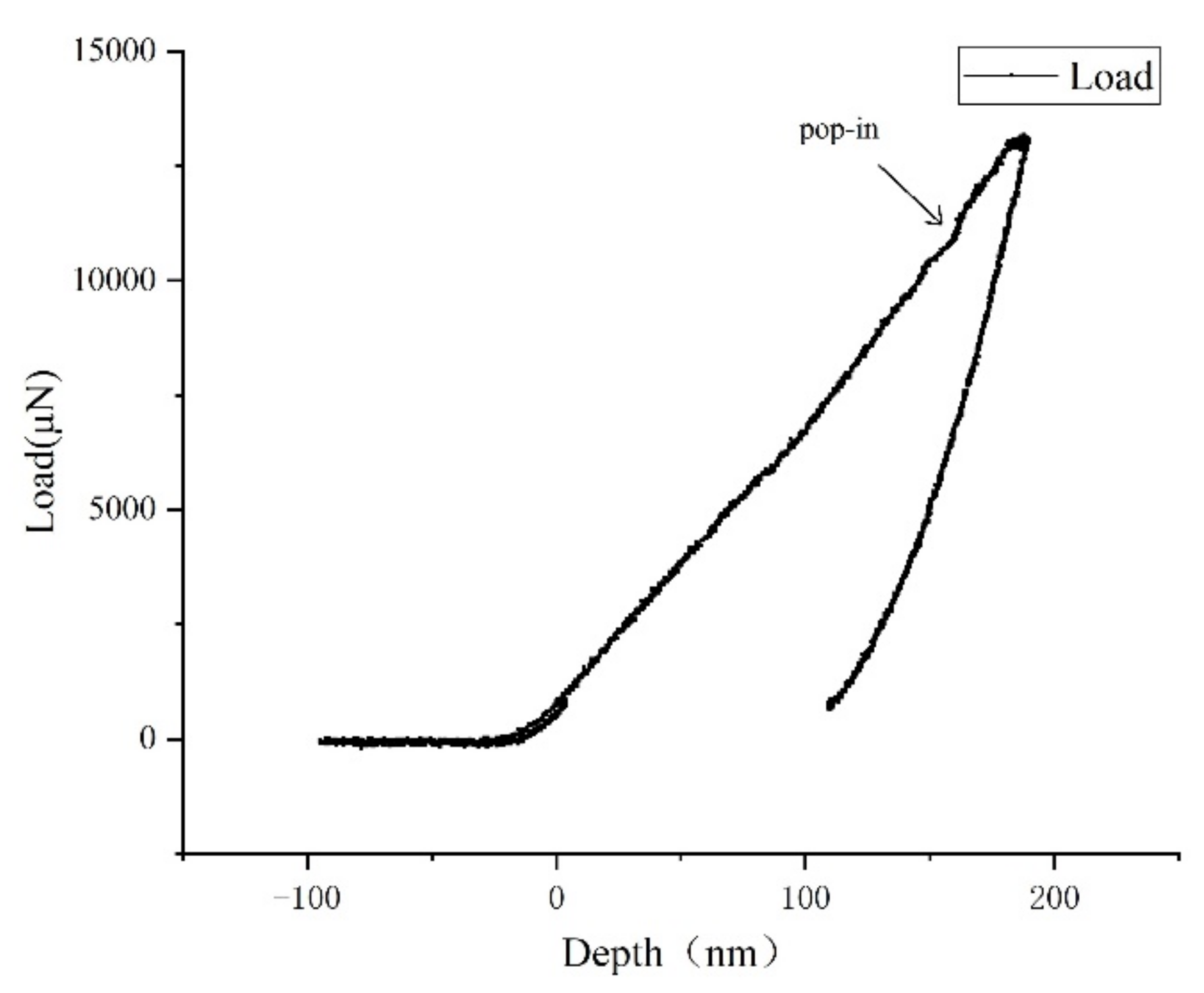
Y-cut lithium niobate crystals were measured using nanoindentation, and the load–displacement curves with different loads were obtained. The elastic modulus and hardness of lithium niobate were obtained. The indentation morphology of lithium niobate surface with different loads was compared, and the critical indentation depths of lithium niobate crystal at a single point ranged from 10 to 20 μN and from 0.105 μm to 0.16 μm.
(2)
The force on abrasive particles was analyzed. The critical-load model was derived by integrating the critical loads and the normal distribution of abrasive particles. The critical loads were related to the number of abrasive particles, the variance of the abrasive particle size, the critical depths, and the hardness of lithium niobate. The critical machining loads of lithium niobate with different particle sizes were obtained, which provided a basis for calculating the critical loads of lithium niobate-free abrasive particles.
(3)
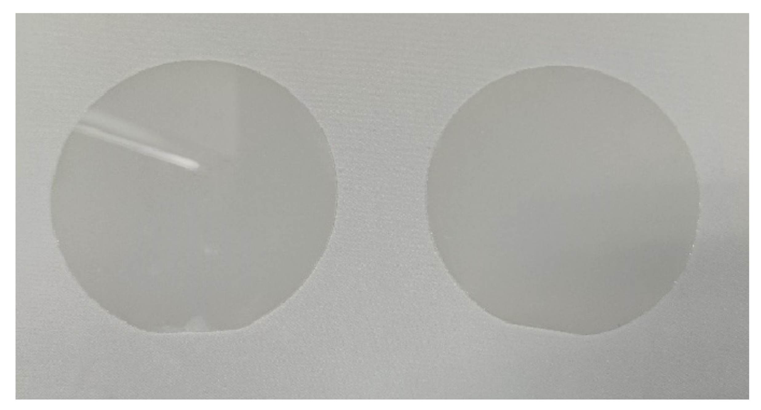
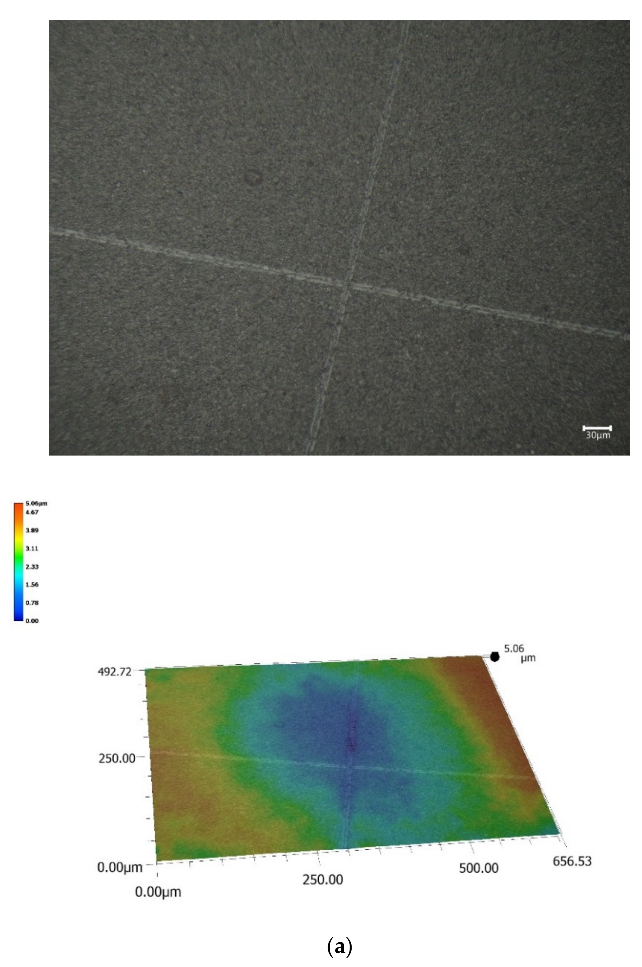
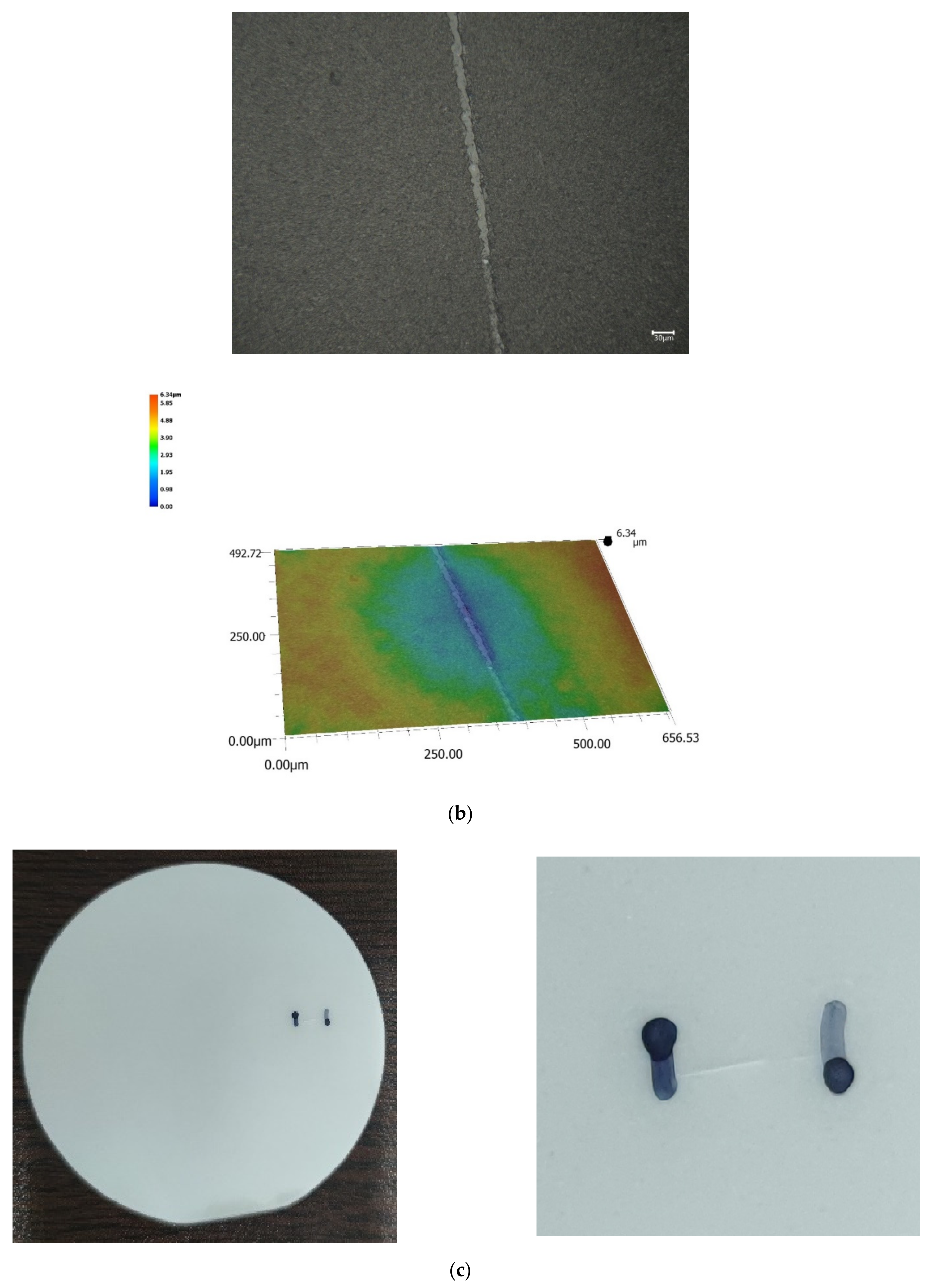
Lithium niobate lapping experiments were carried out. The results show that when the lapping loads were greater than 20 N, there were obvious scratches or even fractures on the surface. When the lapping loads were less than or equal to 20 N, there was no obvious damage on the surface.

Author Contributions

Conceptualization, H.Z. and D.W.; methodology, H.Z. and D.C.; software, H.Z. and D.C.; validation, H.Z.; formal analysis, H.Z. and F.K.; investigation, H.Z.; resources, H.Z. and D.W.; data curation, H.Z. and F.K.; writing—original draft preparation, H.Z.; writing—review and editing, H.Z.; visualization, H.Z.; supervision, H.Z.; project administration, H.Z.; funding acquisition, H.Z. All authors have read and agreed to the published version of the manuscript.

Funding

This research was funded by the National Natural Science Foundation of China (51775509), and Natural Science Foundation of Zhejiang Province (LZ17E050003).

Institutional Review Board Statement

Not applicable.

Informed Consent Statement

Not applicable.

Data Availability Statement

All data are presented in this article in the form of figures and tables.

Conflicts of Interest

The authors declare no conflict of interest.

References

  1. Qi, Y.; Chu, S.; Bi, Y.; Zhou, M.; Yan, W.; Zhang, Y.; Wang, Y.; Yan, B.; Wang, B.; Wu, T.; et al. A compact continuous-wave green laser with line beam for laser projection. Opt. Lasers Eng. 2010, 48, 737–739. [Google Scholar] [CrossRef]
  2. Jasinevicius, R.G.; Pizani, P.S.; Cirino, G.A. Ultraprecision machining of diffraction optical elements on soft semiconductor crystal. Int. J. Adv. Manuf. Technol. 2015, 77, 1145–1154. [Google Scholar] [CrossRef]
  3. Yuan, Z.; Dai, Y.F.; Xie, X.H.; Hou, L.; Peng, W. Research on Ultra—Precise Figuring for CaF2 Single Crystal. Chin. J. Mech. Eng. 2013, 49, 46–51. [Google Scholar] [CrossRef]
  4. Wang, Z.; Shi, C.; Zhang, P.; Yang, Z. Recent Progress of Advanced Optical Manufacturing Technology. Chin. J. Mech. Eng. 2021, 57, 23–56. [Google Scholar] [CrossRef]
  5. Liu, Q.; Liao, Z.; Cheng, J.; Xu, D.; Chen, M. Mechanism of chip formation and surface-defects in orthogonal cutting of soft-brittle potassium dihydrogen phosphate crystals. Mater Des. 2021, 198, 737–739. [Google Scholar] [CrossRef]
  6. Tawakoli, T.; Azarhoushang, B.; Rabiey, M. Ultrasonic assisted dry grinding of 42CrMo4. Int. J. Adv. Manuf. Technol. 2009, 42, 883–891. [Google Scholar] [CrossRef]
  7. Gao, X.; Xue, C.; Chao, Y.; Liu, Y. Optimization method of manufacturing for diamond turning soft-brittle materials’ harmonic diffractive optical elements. Appl. Opt. 2021, 60, 162–171. [Google Scholar] [CrossRef]
  8. Geng, R.; Yan, J. Deformation behaviour of soft-brittle polycrystalline materials determined by nanoscratching with a sharp indenter. Precis. Eng. 2021, 72, 717–729. [Google Scholar]
  9. Plessky, V.; Yandrapalli, S.; Turner, P.J.; Villanueva, L.G.; Koskela, J.; Hammond, R.B. 5 Ghz Laterally-Excited Bulk-Wave Resonators (Xbars) Based on Thin Platelets of Lithium Niobate. Electron. Lett. 2019, 55, 98–100. [Google Scholar] [CrossRef]
  10. Liu, H.; Sang, Y.H.; Sun, D.H.; Wang, D.Z.; Wang, J.Y. Lithium Niobate Crystals in the Information Age: Progress and Prospect. J. Synth. Cryst. 2021, 50, 708–715. [Google Scholar]
  11. Cheng, Y. Photonic integrated circuits on lithium niobate: Today’ s fundamental research for tomorrow’s industry. Acta Phys. Sin. 2020, 42, 277–284. [Google Scholar]
  12. Shang, C.; Tao, S.; Sun, H.; Pan, A.; Zeng, C.; Xia, J. Fully Packaged Thin Film Lithium Niobate Electro-Optic Modulator. Semicond. Optoelectron. 2022, 43, 95–99. [Google Scholar]
  13. Díaz-Tena, E.; Rodríguez-Ezquerro, A.; de Lacalle Marcaide, L.L.; Bustinduy, L.G.; Sáenz, A.E. A sustainable process for material removal on pure copper by use of extremophile bacteria. J. Clean. Prod. 2014, 84, 752–760. [Google Scholar] [CrossRef]
  14. Díaz-Tena, E.; Barona, A.; Gallastegui, G.; Rodríguez, A.; López de Lacalle, L.N.; Elías, A. Biomachining: Metal etching via microorganisms. Crit. Rev. Biotechnol. 2017, 37, 323–332. [Google Scholar] [CrossRef]
  15. Nesprías, F.; Venturino, M.; Debray, M.E.; Davidsonac, E.; Davidsonac, J.M.; Kreinerabc, A.J.; Minskyab, D.; Fischera, M.; Lamagnaab, A. Heavy ion beam micromachining on LiNbO3. Prog. Part. Nucl. Phys. 2009, 267, 69–73. [Google Scholar] [CrossRef]
  16. Sivarajah, P.; Werley, C.A.; Ofori-Okai, B.K.; Nelson, K.A. Chemically assisted femtosecond laser machining for applications in LiNbO3 and LiTaO3. Appl. Phys. A 2013, 112, 615–622. [Google Scholar] [CrossRef]
  17. Yuan, J.; Zhang, F.; Dai, Y.; Kang, R.; Yang, H.; Lü, B. Development Research of Science and Technologies in Ultra-precision Machining Field. Chin. J. Mech. Eng. 2010, 46, 161–177. [Google Scholar] [CrossRef]
  18. Rodríguez, A.; González, M.; Pereira, O.; de Lacalle, L.N.L.; Esparta, M. Edge finishing of large turbine casings using defined multi-edge and abrasive tools in automated cells. Int. J. Adv. Manuf. Technol. 2021. [Google Scholar] [CrossRef]
  19. Bhagavat, S.; Kao, I. Nanoindentation of lithium niobate: Hardness anisotropy and pop-in phenomenon. Mat. Sci. Eng. A-Struct. 2005, 393, 327–331. [Google Scholar] [CrossRef]
  20. Xu, Y.; Yin, Y. Mathematics and Mechanics Principles of Variable Pressure Lapping and Analysis of Removal Efficiency. Chin. Sci. Bull. 2016, 61, 862–871. [Google Scholar]
  21. Pan, J. Research on ultra precision abrasive machining mechanism of monocrystalline SiC substrates. PhD Thesis, Guangdong University of Technology, Guangzhou, China, 2015. [Google Scholar]
  22. Yuan, J.; Zhang, T.; Hang, W.; Ling, Y.; Wang, J.; Zhao, P. Experimental Research on High Efficiency Lapping Machining of Lithium Tantalate Based on Fixed Abrasive Pad. Surf. Technol. 2019, 48, 349–354+371. [Google Scholar]
  23. Zhu, N. Mechanism and Process Research of Lithium Niobate Lapping and Polishing by Fixed Abrasive Pad with a High Efficiency and Low Damage. PhD Thesis, Nanjing University of Aeronautics and Astronautics, Nanjing, China, 2017. [Google Scholar]
  24. Zhang, Z.; Song, Y.; Xu, C. Chemical Mechanical Polishing of Soft-brittle CdZnTe Wafers Using a Developed Environment-friendly Solution. Chin. Mech. Eng. 2014, 25, 3008–3011. [Google Scholar]
  25. Du, J.; Wang, H.; Wang, X. Analysis of Influencing Factors on Critical Load of Adhesion Strength in Scratch Test. Surf. Technol. 2015, 44, 134–139. [Google Scholar]
  26. Zhang, N. Nanoindentation and Chemical Mechanical Polishing of Lithium Niobate Crystals. PhD Thesis, Dalian University of Technology, Dalian, China, 2015. [Google Scholar]
  27. Tun, Z.-S.; Cui, C.-C.; Xie, R.-F.; Huang, H.; Li, B.; Huang, C.J. Research on White-light Interferometer Automatic Scanning Technology Based on Threshold. Chin. Mech. Eng. 2012, 23, 1482–1486. [Google Scholar]
  28. Nguyen Pham, T.N.; Abbes, F. Lecomte Inverse Identification of Single-Crystal Plasticity Parameters of HCP Zinc from Nanoindentation Curves and Residual Topographies. Nanomaterials 2022, 12, 1105–1112. [Google Scholar]
  29. Wang, J.; Liang, J.; Wen, Z.; Yue, Z.; Peng, Y. Unveiling the local deformation behavior of typical microstructures of nickel-based single crystals under nanoindentation. Mech. Mater 2022, 166, 56–59. [Google Scholar] [CrossRef]
  30. Wolf, B.; Richter, A.; Guenther, M. Approaches of quantifying the entire load-depth curve in terms of hardness. Int. J. Mater. Res. 2022, 94, 807–812. [Google Scholar] [CrossRef]
  31. Bouzakis, K.D.; Michailidis, N.; Hadjiyiannis, S.; Skordaris, G.; Erkens, G. Continuous FEM simulation of the nanoindentation Actual indenter tip geometries, material elastoplastic deformation laws and universal hardness. Int. J. Mater. Res. 2022, 93, 862–869. [Google Scholar]
  32. Broitman, E. Indentation Hardness Measurements at Macro-, Micro-, and Nanoscale: A Critical Overview. Tribol. Lett. 2017, 65, 52–59. [Google Scholar]
  33. Tao, K.; Qiao, J.C.; He, Q.F.; Song, K.K.; Yang, Y. Revealing the structural heterogeneity of metallic glass: Mechanical and nanoindentation. Int. J. Mater. Res. 2021, 201, 66–69. [Google Scholar]
Figure 1. Flow chart for experiments.
Processes 10 00912 g001
Figure 2. Lithium niobate polished sheet with a diameter of 3 inches.
Processes 10 00912 g002
Figure 3. Schematic diagram of free abrasive processing and removal mechanism.
Processes 10 00912 g003
Figure 4. Analysis of the geometric relationship of the force on abrasive particles.
Processes 10 00912 g004
Figure 5. Loading and unloading curves under six kinds of loads.
Processes 10 00912 g005
Figure 6. AFM scan of indentation of lithium niobate crystal with different low loads. (a) 300 μN; (b) 500 μN; (c) 1000 μN; (d) 5000 μN; (e) 8000 μN; (f) 10,000 μN.
Processes 10 00912 g006aProcesses 10 00912 g006b
Figure 7. Indentation depths with 8mN and 10mN loads. (A) 8 mN Load Indentation Depth; (B) 10 mN Load Indentation Depth.
Processes 10 00912 g007aProcesses 10 00912 g007b
Figure 8. Elastic modulus of LN under different loads.
Processes 10 00912 g008
Figure 9. LN hardness under different loads.
Processes 10 00912 g009
Figure 10. LN surface fracture under high load. (a) 20 mN; (b) 30 mN.
Processes 10 00912 g010
Figure 11. LN surface fracture under high loads. (a) 11 mN; (b) 13 mN; (c) 15 mN.
Processes 10 00912 g011
Figure 12. Loading and unloading curves under 13 mN.
Processes 10 00912 g012
Figure 13. Indentation depths of LN at 11 mN and 20 mN. (a) 11 mN Load Indentation Depth; (b) 20 mN Load Indentation Depth.
Processes 10 00912 g013
Figure 14. Observation of low loads and critical lapping surface. (a) Two-dimensional observation at 15 N; (b) two-dimensional observation at 20 N.
Processes 10 00912 g014aProcesses 10 00912 g014b
Figure 15. Observation of high-load lapping surface. (a) Two-dimensional and three-dimensional observation of a 25 N load; (b) Two-dimensional and three-dimensional observation of a 35 N load; (c) 40 N Load Surface Observation.
Processes 10 00912 g015aProcesses 10 00912 g015b
Table 1. Normal distribution parameters of Al2O3 abrasive particles.
Alumina Abrasive
(Particle Size)
Average Value (μm) Standard Deviation (μm)
W1410.53.5
W75.251.75
W3.52.50.83
W1.51.250.42
Table 2. Test parameters.
Parameter12345
Load (kg)1.522.53.54
Rotating speed (r/min)2020202020
Time (min)3030303030
Table 3. Critical loads of LN crystal with different abrasive grains.
Alumina Abrasive
(Particle Size)
Total Number of Abrasive Particles (106)Critical Load (N)
W1441.349.63
W7165.3819.23
W3.5729.2839.92
W1.52917.1278.92
Publisher’s Note: MDPI stays neutral with regard to jurisdictional claims in published maps and institutional affiliations.

