Abstract
This paper aims to propose a new algorithm for designing thermal vapor compressors (TVCs) using given operation parameters. First, an axisymmetric model was used to simulate a TVC, and the results were compared with those from published experimental results. A simulation set was designed to analyze the TVC dimensions, and then statistically-significant parameters (p-value < 0.05) were chosen for the subsequent studies. Thereafter, three parametric lengths were defined and a model presenting entrainment ratio (ER) was developed using a set of simulation results. The obtained characteristic equation allows us to scale (up or down) the TVC to different capacities, calculate the real-time sizes or predict the performance. It was found that the critical “TVC/primary nozzle” throat diameter ratio is constant in every scale-up study, depending on operation conditions. By establishing a characteristic graph, the approach was expanded for a broader algorithm. The comparative results revealed that this approach is able to predict the ER for every scaling study with an error of less than 2.8%. This approach can be used to devise TVCs ejectors using any given ER and capacity within the ranges of possible usage.
1. Introduction
Desalination of seawater is going to be the central part of sustainable urban water management. Thermal desalinates are in two classic types, including multi-stage flash (MSF) and multi-effect distillation (MED). By blowing high-pressure steam through the primary nozzle at the thermal vapor compressor (TVC) suction, the motive steam speeds up to supersonic velocity. This results in a high level of vacuum, causing the secondary stream to flow through the TVC, hence the name steam ejector.
Several researchers have studied TVCs and ejectors experimentally [1]. Many researchers have investigated the application of computational flow dynamics (CFD), proving that these methods are inexpensive, and reliable [2,3,4], including reactor design, aviation, and supersonic streams. Some of these efforts have primarily been focusing on the determination of primary nozzle Mach number, ejector area ratio, entrainment ratio (ER), compression ratio (CR), stagnation temperature, and pressure ratio. Later, these efforts pivoted to further improve the operating conditions and geometrics, by employing finite volume and finite element methods [4]. Petrovic et al. (2018) compared the analytical, experimental, and numerical methods and presented a new design methodology working on a constant nozzle area ratio for different mass flow rates [5]. Balamurugan et al. (2008) found that the CFD models provide satisfying predictions for the experimental results and revealed an optimum ratio for the nozzle to throat area ratio [6]. Employing dimensionless parameters, K. Zhang et al. [7] demonstrated that depending on the ejector model, there is an optimal nozzle position for a given set of operating conditions and fixed geometries. Dong et al. [1] studied the effect of the operating temperature, exit position, and the ejector area ratio on the performance of the steam ejector. They concluded that a steam ejector could operate successfully for a particular configuration size to generate outlet steam within a temperature range of 40–70 °C. Fu et al. [8] revealed a range of primary nozzle outlet diameters at which the ejector operates at its ideal performance. For a desired ER and CR, Sharifi et al. (2013) examined the influence of main geometric parameters on the performance of TVC and presented their findings in the form of a number of dimensionless numbers that allow convenient design [9]. To propose a strategy for estimating geometrical sizes to enhance the TVC operation, Park [10] suggested that the mixing length of TVC should be set 5–10 times the diameter of the constant-diameter zone.
Furthermore, Kouhikamali et al. (2012) proposed a range of converging angles for the mixing section [11]. Sharifi et al. (2013) developed an equation to correlate the ER to the dimensionless volume and length [9]. Although several studies have investigated TVC dimensionless parameters in the literature, this paper proposes a new methodology that obtains the governing parameters by conducting lesser case studies. Previous studies tried to correlate the performance parameters (capacity, entrainment, etc.) to the dimensions of various TVCs. By contrast, this paper introduces a methodology based on dimensionless parameters and a characteristic equation for upscaling purposes by developing an analogy among all TVCs. Practically, a platform has been proposed in this paper to design different TVCs, using any given ER, CR, and capacity.
2. Materials and Method
2.1. Setup
A schematic form of a typical TVC is shown in Figure 1. The constant area length (Lc), diverging diameter (Dd), and diverging length (Ld) have almost no impact on the interactions of the subsonic and supersonic inlet streams; therefore, they were not considered for optimization in TVC design [9].
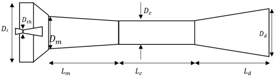
Figure 1.
A schematic presentation of a typical TVC.
Equations (1) and (2) introduce the entrainment ratio (ER) and compression ratio (CR) that allow us to quantitively analyze the TVC performance based on the operating conditions as well as the dimensional parameters:
where P and m are pressure and mass flow rate. Depending on the TVC operation parameters, three different states can be hypothesized, namely double-choke, single-choke, and backflow mode. In a typical TVC, as long as the discharge pressure is less than Pmax, ER remains unchanged, but once the discharge pressure surpasses the Pmax, ER starts to decrease, leading to backflow initiation. With further discharge pressure increase, the TVC performance fails, and the flow direction alters. The schematic of TVC performance at different conditions is shown in Figure 2.
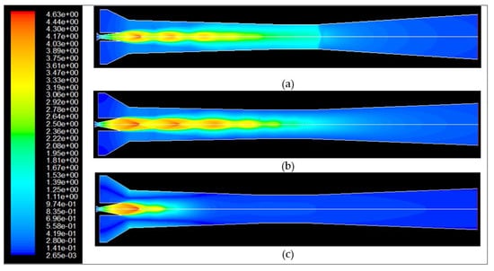
Figure 2.
Mach number and various forms of operation mode in the TVC, (a) double-choked, (b) single-choked, (c) backflow.
2.2. Modeling and Simulation
Conservation laws of mass, energy, and momentum were used as the basis for establishing the model.
2.2.1. Balance Equations
Conservation equation Equation (3) for compressible fluid was used to model the behavior of the thermo-compressor and the flow pattern of steam.
A thermo-compressor model was also developed based on the time-averaged unsteady-state Navier–Stokes equation Equations (4) and (5) and heat transfer equation Equations (6) and (7). Due to symmetric geometry, we employed a 2D axisymmetric approach to simulate the TVC, and the tangential derivations of cylindrical coordinates were skipped [12,13]. The employed 2D axisymmetric model in this study can be presented as:
- Turbulence model
The “realizable” k-ε model was selected to describe the system turbulence as it predicts an accurate spreading rate of the round jet. Hemidi et al. (2009) proved that over the whole range of operating conditions, the overall deviation is below 10% for the k-ε model Equations (8) and (9), while the accuracy of the k-ω-sst model is insignificant [14].
where Sk and Sε represent the kinematic energy and turbulent dissipation rate, respectively.
2.2.2. Solution to the Model Equations
The governing equations were discretized by the finite volume method. A second-order upwind scheme was adopted for spatial discretization of the convection terms using commercial CFD software package Fluent® 6.3 (Ansys—Canonsburg, PA USA). The governing partial differential equations were implicitly solved by the pressure-based implicit coupled method [15]. This segregated solver was used in the simulation, and the convergence criteria of the iterative solution were ensured by considering the residual of all variables to be less than 1 × 10⁻⁶ for both continuity and energy equations.
2.2.3. Boundary Conditions
In this work, boundary conditions such as temperature and pressure were kept fixed by specifying the pressure inlet for both motive steam and secondary flows. Motive and low-pressure flows entered the TVC at 200 and 49 (°C) with a pressure of 1260 and 11.6 kPa, respectively. These boundary conditions are adopted from typical operating conditions of a TVC in the utility facility of a local power plant. The process was assumed to be adiabatic, therefore, the output flow, temperature and pressure were calculated based on mass and energy balance equations. Given the lower operating pressure of the working fluid across the entire TVC (except for the nozzle head), the steam was assumed to be an ideal gas [16].
2.2.4. Identification of the Main Characteristic Lengths of TVC
Throat diameter of the primary nozzle determines the mass flow rate passing through the primary nozzle, while the TVC throat diameter controls the total output mass flow. The output mass flow rate of the primary nozzle was specified based on the capacity of a conventional MED. The overall mass flow rate of steam () through the primary nozzle was developed by [9]:
where γ is the specific heat ratio, A is the cross-section area, and M is the Mach number. For the nozzle, the mass flow rate was calculated assuming M = 1 at the nozzle throat. Also subscript “0” shows the stagnation status of the fluid.
2.3. Method
First, a series of simulations were performed to investigate the effect of sizing parameters of throat diameter or constant diameter zone (Dc), mixing zone length (Lm), inlet diameter (Di), and mixing zone diameter (Dm) on ER at a fixed CR. Second, the identified geometrical parameter with the lowest impact on ER was omitted from the proposed model, and the geometrical parameter with the most significant influence on ER was set to its optimum value. It should be noted that the effects of the diverging zone, constant diameter region length, and other sizes were not studied, as they have been proved to be insignificant factors [9]. The ER property at a fixed boundary condition is affected by their geometrical parameters. On the other hand, the nozzle diameter dictates the mass flow rate of motive steam, which provides the propulsion force created by motive steam or the highest possible CR. Therefore, by defining dimensionless length as the ratio of geometrical parameters to nozzle diameter, the “ER/CR” ratio can be implicitly formulated.
2.4. Computational Grid
A computational grid for the axisymmetric geometry of a thermo-compressor was developed by employing a uniform mesh (Figure 3). A grid independency test was performed, and it was observed that by increasing the cell number from 19,000 to 34,700, the variation of all mass flow rates was less than 0.25%; therefore, the total cell number of 34,700 was used in all the simulation studies. The y+ values in the grids near the wall, were chosen to be 45 < y+ < 90 in order to effectively predictwall-fluid tension (wall law) [17].
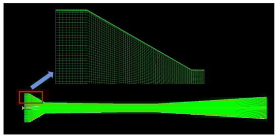
Figure 3.
The grid elements of the simulated TVC.
2.5. Design of Experiments
The design of the experiment has been used twice to find the relative importance of the employed parameters. The data from analysis of each run were collected, analyzed, and fit into a second-order polynomial (triple–interaction terms were omitted) followed by an analysis of variance (ANOVA):
where Y is the response α0, αi, αii and αij are the regression coefficients estimated using the equation for the intercept, linearity, square, and interaction, respectively; and Xi and Xj represent the independent variables.
3. Results and Discussion
3.1. Model Validation
To validate the model, the obtained ER results were compared with those published by Sriveerakul [18]. Figure 4 shows a satisfying consistency in ER results between the simulation results and those from the experiment and simulation [18] within the double-choke region. At ER > 35 mbar where single-choke occurs, ER becomes sensitive, and small instrument errors or changes in back pressure quantity alter the results, therefore, the results do not live up to the expected outcomes. Nevertheless, the results from the simulation are also in good agreement with those from Sriveerakul [18]. It should also be mentioned that the single-choke zone of the performance curve is outside of the scope of our discussion.
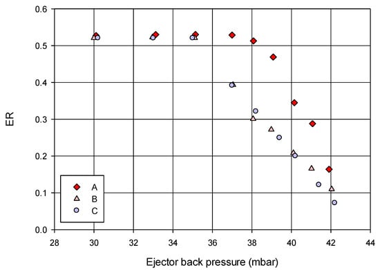
Figure 4.
Comparison of the simulated and experimental results demonstrating the changes in ER vs. discharge pressure. The symbols A and B are the experimental and simulatin values (respectively) obtained by Sriveerakul et al. [18]. Symbol C represents the values of the current work.
The figure also confirms that for any given ER, the maximum backpressure has less than 8% error which is further evidence of the validity of the proposed method. Additionally, the simulation results in the proper back-pressure region (back pressure < 35 mbar), show a significant overlap with those from experiments.
3.2. The Effect of Various Geometrical Parameters on the Performance of TVC
Box–Behnken Design (BBD) was employed to establish a number of simulations to evaluate the effect of geometrical parameters and to eliminate statistically-insignificant model terms from the final model. Four factors, including Di (A), Dc (B), Dm (C), and Lm (D) were considered, each at three levels, resulting in a total of 29 simulations (Table 1). The factor levels selected in our modeling study were within a rational range based on conventional industrial TVC dimensions [17]. Initially, the four mentioned parameters’ effects were analyzed for the discharge pressure of 30 kPa (CR = 2.5), while the size of the primary nozzle throat was set at 80 mm. Analysis of variance (ANOVA) was performed to analyze the variables (Table 1) and check for variable significance.

Table 1.
Performed test for ER calculation for specified lengths (CR = 2.5 and primary nozzle throat = 80 mm); all sizes are in mm.
Table 2 shows the ANOVA table for the truncated form for the analysis. From the p-value (prob. > F), it was found that the parameter A (TVC inlet diameter) shows a lack of importance; therefore, it was omitted from the rest of the study. The final quadratic model with R2 > 97% presents reliable ER prediction with significant model terms. From the analysis of factors, the throat diameter (B) was found to be the most influential parameter on the TVC performance (maximum F-value), followed by the mixing region inlet diameter (C) and the mixing length (D). As a result, the inlet diameter (Di) and throat diameter (Dc) are the least and most effective lengths, respectively. To further simplify the optimization, the Dc value was set to be on its highest possible value during the rest of study. The Di was also eliminated from the model during ANOVA analysis.
Table 2.
Analysis of variance table for the response model of the quadratic form.
3.3. Dimensionless Parameters for Scale-Up
Since Dc was identified as the most effective parameter, it was kept at its max value, Dc_max; and the effect of other parameters was considered for further RSM investigation. By increasing the primary nozzle throat diameter, the mass flow rate of motive steam and momentum increase. This increase pushes back the shock wave from constant diameter to diverging zone, preventing single-choke and achieving higher CR. As mentioned before,, and are key parameters for ER determination, so is for the CR. With the ultimate purpose of scaling up, dimensionless parameters (), () and () were defined as independent factors.
In a hypothetical TVC (CR = 3) with given geometric parameters Lm = 1035 mm, Dth = 106 mm, Dm = 6000 mm, the highest possible value for Dc was calculated (870 mm). Based on Figure 1, a 3-level miscellaneous design under RSM was adopted (DesignExpert7.0.0.) and a set of tests with two factors including 8.2 ≤ ≤ 11.32 and 47.16 ≤ ≤ 66.04 was considered, where the () was kept unchanged at the maximum value 8.2. The minimum value of () was chosen based on commercial TVCs to keep the angle of the converging zone higher than zero degree [17]. The maximum values of dimensionless lengths were selected based on the highest possible value to keep the TVC’s performance within the double-choke mode. A total of 13 simulations was conducted for different geometric parameters, and the ER values were investigated accordingly (Table 3).
Table 3.
Performed simulation for calculation of ER for the specified dimensionless values (CR = 3), Dth = 106 mm and = 8.2.
The ANOVA was carried out for Table 3 and Equation (12) was developed (R2 > 98%.) to evaluate the ER as a function of dimensionless parameters for CR ≤ 3 and the maximum value of () = 8.2. Equation (12) represents the characteristic equation for the design and is used in size calculations and scaling-up.
Limitations for the motive steam capacity of 15.62 (kg/s):
In order to increase the capacity, one approach can be to increase the primary nozzle diameter (Dth). This leads to a number of results involving (i) increasing the mass flow of motive steam that reduces ER, and (ii) shifting the shock position from constant diameter to the diverging zone. Maintaining the ER at its maximum value (ERmax = 0.95) and for different capacities, different levels of dimensionless (), () and () were considered, and a comparative study was conducted between the obtained simulation results and those from the characteristic equation Equation (12) (Table 4). In this table, the () was kept at maximum value of 8.2, and different (), () and Dth were tested to compare the ER values from simulations and those from the characteristic equation. As it is evident, different TVCs with different parameters, Equation (12) proved to provide a reasonable approximation of the ER values (error ≤ 3%).
Table 4.
The prediction of ER values by the characteristic equation for a wide variety of TVCs— is at the maximum of 8.2.
Based on the simulation data (Table 4) the following conclusions were drawn. For a fixed CRmax value and under fixed boundary conditions (temperature and pressure of both motive and secondary streams), regardless of ER value, the maximum possible ratio of the TVC’s nozzle diameter to primary nozzle throat diameter was the constant number 8.2 for all capacities to maintain a proper operation. What it means is that if 8.2 ≤ , the momentum created by motive steam cannot push the oblique shock wave from the constant diameter to the diverging zone. In this situation, the shock wave moves from the diverging zone into the TVC’s throat, thereby preventing double-choke (Figure 2c). For any capacity, the allowed values for () and () for the application of Equation (12) are unique. Figure 5a shows the variation of and vs. capacity of TVC. With the increase in motive steam capacity, more cross-section area is demanded, resulting in an increase in . As can be seen in Figure 5a, by increasing the capacity of a TVC, the dimensionless length of decreases. Kouhikamali and Sharifi [11] reported that a low mixing angle leads to increased mixing efficiency and consequently the ER, which is in agreement with our findings.
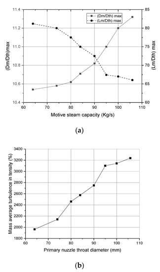
Figure 5.
The effect of scale-up on TVC parameters. Variation of and vs. motive steam capacity (a) and mass average turbulence intensity (%) vs. primary nozzle throat diameter (b).
Figure 5b shows the mass average turbulence intensity over the whole TVC vs. the primary nozzle diameter of TVC. It reveals that by increasing the primary nozzle diameter (capacity), mass-average turbulence intensity increases, i.e., efficient mixing of supersonic and subsonic streams. Inversely, with the decrease of Dth, a longer mixing zone is required to accommodate a proper mixture of the inlet flows to keep ER close to 0.95.
Figure 6 schematically shows the changes in ER as well as the motive steam capacity (blue spots—collected from Table 4) vs. the changes in and . At ERmax (ER = 0.95), the arrows determine the ranges in which Equation (12) can be used. The limitation varies with the change in capacity.
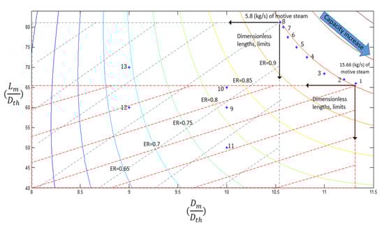
Figure 6.
The contour of ER and motive steam capacity vs. the dimensionless parameters (CR = 3)—the determined spots are test numbers from Table 4.
4. Conclusions
TVC was characterized by introducing dimensionless parameters and CFD analysis. We examined the effect of individual geometrical parameters on entrainment and identified the insignificant parameters to amend in the follow-up study. In the next step, we defined three dimensionless parameters that originated from significant parameters determined during prior studies. Emphasizing on the critical impact of the nozzle throat diameter on ER, our study showed that among different capacities with identical ER and CR, the ratio is approximately constant. Regardless of the TVC size, the () should be kept under its maximum value to avoid compressor malfunction. This allows us to use a characteristic graph (Figure 6) as a practical tool to design different TVCs for any set of operating conditions.
Furthermore, the effect of each dimensionless parameter was studied individually at a constant ER level which shows that by increasing the capacity, and the mass average turbulence intensity increase. Inversely, by lowering the capacity at a constant ER level increases to compensate for the required turbulence for an effective mixture. Moreover, it is concluded that at constant (), if () and () satisfy the characteristic equation, the TVC of interest can be designed and scaled-up with less than 3% ER error.
Author Contributions
Conceptualization, M.M., M.V., A.S. and A.M.-Z.; data curation, M.M. and M.V.; formal analysis, M.M., M.V. and A.M.-Z.; funding acquisition, M.V., A.S. and A.M.-Z.; investigation, M.M., M.V. and A.M.-Z.; methodology, M.M., M.V., A.S. and A.M.-Z.; project administration, A.S. and A.M.-Z.; resources, A.S.; software, M.M. and M.V.; supervision, A.S. and A.M.-Z.; validation, M.M. and M.V.; visualization, M.M. and M.V.; writing—original draft, M.V. and A.M.-Z.; writing—review and editing, M.M., M.V. and A.S. All authors have read and agreed to the published version of the manuscript.
Funding
The article processing charge of this article was provided by the Jackson library of University of North Carolina at Greensboro (UNCG), North Carolina, USA. The CREST Center for Bioenergy of North Carolina Agricultural and Technical State University (NCAT) has also financially contributed to this article by NSF award# 1736173.
Institutional Review Board Statement
Not applicable.
Informed Consent Statement
Not applicable.
Data Availability Statement
Data sharing not applicable.
Conflicts of Interest
The authors declare no conflict of interest.
Nomenclature
| Abbreviation | |
| CFD | Computational Fluid Dynamics |
| CR | Compression Ratio |
| ER | Entrainment Ratio |
| MED | Multi-Effect Distillation |
| MSF | Multi-Stage Flash |
| TVC | Thermal Vapor Compressor |
| Variables | |
| D (mm) | Diameter |
| L (mm) | Length |
| T (K) | Temperature |
| P (kPa) | Pressure |
| m (kg s−1) | Mass flow rate |
| M | Mach number |
| A (m2) | Cross-section area |
| U (m s−1) | Velocity |
| G (m m−2) | Gravitational acceleration |
| E (j) | Total energy |
| Greek letters | |
| γ | Specific heat ratio |
| μ | Dynamic viscosity |
| ρ | Density |
| Subscripts | |
| th | Throat |
| m | Mixing zone |
| max | maximum |
| c | Constant area zone |
| d | Diverging zone |
| 0 | Stagnation properties |
References
- Dong, J.; Yu, M.; Wang, W.; Song, H.; Li, C.; Pan, X. Experimental investigation on low-temperature thermal energy driven steam ejector refrigeration system for cooling application. Appl. Therm. Eng. 2017, 123, 167–176. [Google Scholar] [CrossRef]
- Darvanjooghi, M.H.K.; Malakootikhah, M.; Magdouli, S.; Brar, S.K. Ethylene and cyclohexane co-production in the fixed-bed catalytic membrane reactor: Experimental study and modeling optimization. J. Membr. Sci. 2021, 643, 120044. [Google Scholar] [CrossRef]
- Hasany, M.; Malakootikhah, M.; Rahmanian, V.; Yaghmaei, S. Effect of hydrogen combustion reaction on the dehydrogenation of ethane in a fixed-bed catalytic membrane reactor. Chin. J. Chem. Eng. 2015, 23, 1316–1325. [Google Scholar] [CrossRef]
- Croquer, S.; Poncet, S.; Galanis, N. Comparison of ejector predicted performance by thermodynamic and CFD models. Int. J. Refrig. 2016, 68, 28–36. [Google Scholar] [CrossRef]
- Petrovic, A.; Svorcan, J.; Pejcev, A.; Radenkovic, D.; Petrovic, A. Comparison of novel variable area convergent-divergent nozzle performances obtained by analytic, computational and experimental methods. Appl. Math. Model. 2018, 57, 206–225. [Google Scholar] [CrossRef]
- Balamurugan, S.; Gaikar, V.; Patwardhan, A. Effect of ejector configuration on hydrodynamic characteristics of gas–liquid ejectors. Chem. Eng. Sci. 2008, 63, 721–731. [Google Scholar] [CrossRef]
- Zhang, K.; Zhu, X.; Ren, X.; Qiu, Q.; Shen, S. Numerical investigation on the effect of nozzle position for design of high performance ejector. Appl. Therm. Eng. 2017, 126, 594–601. [Google Scholar] [CrossRef]
- Fu, W.; Liu, Z.; Li, Y.; Wu, H.; Tang, Y. Numerical study for the influences of primary steam nozzle distance and mixing chamber throat diameter on steam ejector performance. Int. J. Therm. Sci. 2018, 132, 509–516. [Google Scholar] [CrossRef]
- Sharifi, N.; Boroomand, M. An investigation of thermo-compressor design by analysis and experiment: Part 2. Development of design method by using comprehensive characteristic curves. Energy Convers. Manag. 2013, 69, 228–237. [Google Scholar] [CrossRef]
- Park, I. Robust numerical analysis based design of the thermal vapor compressor shape parameters for multi-effect desalination plants. Desalination 2009, 242, 245–255. [Google Scholar] [CrossRef]
- Kouhikamali, R.; Sharifi, N. Experience of modification of thermo-compressors in multiple effects desalination plants in Assaluyeh in IRAN. Appl. Therm. Eng. 2012, 40, 174–180. [Google Scholar] [CrossRef]
- Sharifi, N. Axisymmetric and three dimensional flow modeling within thermal vapor compressors. Heat Mass Transf. 2013, 49, 1489–1501. [Google Scholar] [CrossRef]
- Le Hocine, A.E.B.; Poncet, S.; Fellouah, H. CFD modeling and optimization by metamodels of a squirrel cage fan using OpenFoam and Dakota: Ventilation applications. Build. Environ. 2021, 205, 108145. [Google Scholar] [CrossRef]
- Hemidi, A.; Henry, F.; Leclaire, S.; Seynhaeve, J.-M.; Bartosiewicz, Y. CFD analysis of a supersonic air ejector. Part II: Relation between global operation and local flow features. Appl. Therm. Eng. 2009, 29, 2990–2998. [Google Scholar] [CrossRef] [Green Version]
- Friso, D. Mathematical Modelling of the Entrainment Ratio of High Performance Supersonic Industrial Ejectors. Processes 2022, 10, 88. [Google Scholar] [CrossRef]
- Thongtip, T.; Aphornratana, S. An alternative analysis applied to investigate the ejector performance used in R141b jet-pump refrigeration system. Int. J. Refrig. 2015, 53, 20–33. [Google Scholar] [CrossRef]
- Sharifi, N.; Boroomand, M. An investigation of thermo-compressor design by analysis and experiment: Part 1. Validation of the numerical method. Energy Convers. Manag. 2013, 69, 217–227. [Google Scholar] [CrossRef]
- Sriveerakul, T.; Aphornratana, S.; Chunnanond, K. Performance prediction of steam ejector using computational fluid dynamics: Part 1. Validation of the CFD results. Int. J. Therm. Sci. 2007, 46, 812–822. [Google Scholar] [CrossRef]
Publisher’s Note: MDPI stays neutral with regard to jurisdictional claims in published maps and institutional affiliations. |
© 2022 by the authors. Licensee MDPI, Basel, Switzerland. This article is an open access article distributed under the terms and conditions of the Creative Commons Attribution (CC BY) license (https://creativecommons.org/licenses/by/4.0/).