Article

Optimal Current Allocation Strategy for Hybrid Hierarchical HVDC System with Parallel Operation of High-Voltage and Low-Voltage DC Lines

School of Electrical Engineering, Southeast University, Nanjing 210096, China
*
Author to whom correspondence should be addressed.
Processes 2022, 10(3), 579; https://doi.org/10.3390/pr10030579
Submission received: 24 February 2022 / Revised: 13 March 2022 / Accepted: 14 March 2022 / Published: 16 March 2022
(This article belongs to the Special Issue Modeling, Analysis and Control Processes of New Energy Power Systems)

Abstract

:
For long-distance and bulk-power delivery of new energy, high-voltage direct current (HVDC) is a more effective way than high-voltage alternative current (HVAC). In view of the current capacity disparity between line commutated converter (LCC) and voltage source converter (VSC), a hybrid hierarchical HVDC topology with parallel operation of 800 kV and 400 kV DC lines is investigated. The optimal current allocation method for hybrid hierarchical HVDC is proposed distinct from the same rated current command configuration method of high-voltage and low-voltage converters in traditional topology. Considering the transmission loss reduction of the HVDC system, a multi-order fitting function of transmission loss including LCC converter stations, VSC converter stations and DC lines is established. To minimize the transmission loss and the voltage deviation of key DC nodes comprehensively, a multi-objective genetic algorithm and maximum satisfaction method are utilized to obtain the optimal allocation value of rated current command for high-voltage and low-voltage converters. Through the optimization model, an improved constant current controller based on the current allocation strategy is designed. The hybrid hierarchical HVDC system model is built in PSCAD software, and simulation results verify the effectiveness of the proposed topology and optimal current allocation strategy.

1. Introduction

HVDC is a critical technology for grid interconnection and massive energy transmission with the increasing conversion of fossil fuel-based grids to renewable energy-based grids [1,2,3]. In 2020, global renewable energy increased by 260 gigawatts (GW), mainly composed of wind power (127 GW) and photovoltaic power (111 GW) [4]. To deliver new energy from resource-rich areas to load-concentrated areas, HVDC is more cost-effective than HVAC. Throughout the development of HVDC technology over the last decade, it has overcome many technical obstacles faced by HVDC grids [5,6].
The application of HVDC can realize the interconnection of multiple new energy power grids. In Figure 1, the new energy power system based on HVDC is composed of thermal power plants, photovoltaic power stations, wind farms, sending-end converter stations, DC lines, receiving-end converter stations, and receiving-end grids. Conventional LCC-HVDC technology is widely used, but it presents many disadvantages, such as commutation failure, consumption of a large amount of reactive power, and so on. Although VSC-HVDC can avoid the technical bottlenecks of LCC-HVDC, the short-boards for smaller transmission capacity and lower voltage level also limit its development for new energy integration [7]. Therefore, some scholars proposed hybrid HVDC, which combines LCC-HVDC and VSC-HVDC [8]. However, there are some differences between LCC and VSC in the current capacity and control method. Therefore, it is critical to design the topology and control strategy of the hybrid HVDC, which can make full use of their advantages in this paper.
With the development of VSC converter technology, hybrid HVDC transmission technology integrating LCC and VSC converter has attracted extensive attention. The existing literature focuses on the topology of hybrid HVDC transmission systems [9,10,11], control and protection strategies [12,13,14], small-signal stability analysis [15,16,17], experimental platforms [18,19,20], etc. In November 2020, China approved the Baihetan-Jiangsu HVDC project, which adopts hybrid cascade multi-terminal technology for the first time in the world. The receiving-end station of the transmission project adopts three modular multi-level converters (MMC) in parallel and then connected in series with LCC, which may cause MMC power imbalance and reverse transmission risk after AC or DC faults. The literature [21] proposes an AC fault ride-through strategy for Baihetan HVDC based on a modified DC chopper and enhanced VDCOL (voltage-dependent current order limiter), which can realize stable fault ride-through of HVDC in commutation failure mitigation and overvoltage suppression. In December 2020, the Kunliulong HVDC project was put into operation as the first multi-terminal hybrid HVDC project of 800 kV in the world. Since different converters present various fault characteristics, the literature [22] studied the traveling wave characteristics and verified the adaptability of traveling wave protection in software PSCAD. For HVDC fault detection, the literature [23] designed an improved identification scheme by comparing current polarity with transient current limiting boundary on the basis of full-utilizing capacity of the converter, and intensive simulation is carried out to prove the accuracy and coordination of the proposed scheme.
The above research results enrich the theoretical basis of the hybrid HVDC, but most of the existing topologies cannot make full use of the current capacity of LCC. The cascade technology of the Baihetan HVDC project has high requirements for the current coordinated control of three VSC converters in [24]. To coordinate the current capacity of LCC and VSC, a hybrid hierarchical HVDC is designed in this paper, which can not only make full use of the current capacity of LCC but also improve the ability to connect weak systems by utilizing VSC. The coordination control method is the focus of this paper for its consideration of different converters, different DC lines and loss reduction of HVDC transmission involved in this topology, differing from the same rated current command configuration method of high-voltage and low-voltage converters in traditional topology. The main contributions of this paper are summarized as follows:
(1) A hybrid hierarchical HVDC topology with parallel operation of 800 kV and 400 kV DC lines is designed. By considering the LCC converter station, VSC converter station and DC line, the HVDC transmission loss model is established.
(2) To minimize the transmission loss and the voltage deviation of key DC nodes comprehensively, a multi-objective genetic algorithm and maximum satisfaction method are used to obtain the optimal allocation value of rated current command for high-voltage and low-voltage converters. An improved constant current controller based on optimal current allocation strategy is designed and validated in PSCAD.
The topology of the hybrid hierarchical HVDC system is depicted in Section 2. In Section 3, the HVDC transmission loss model based on the multi-order fitting method is formed in detail. In Section 4, improved HVDC control based on the current optimal allocation method considering the multi-objective optimization method is designed. Simulation results based on PSCAD software and discussion are presented in Section 5. Finally, we conclude this paper in Section 6.

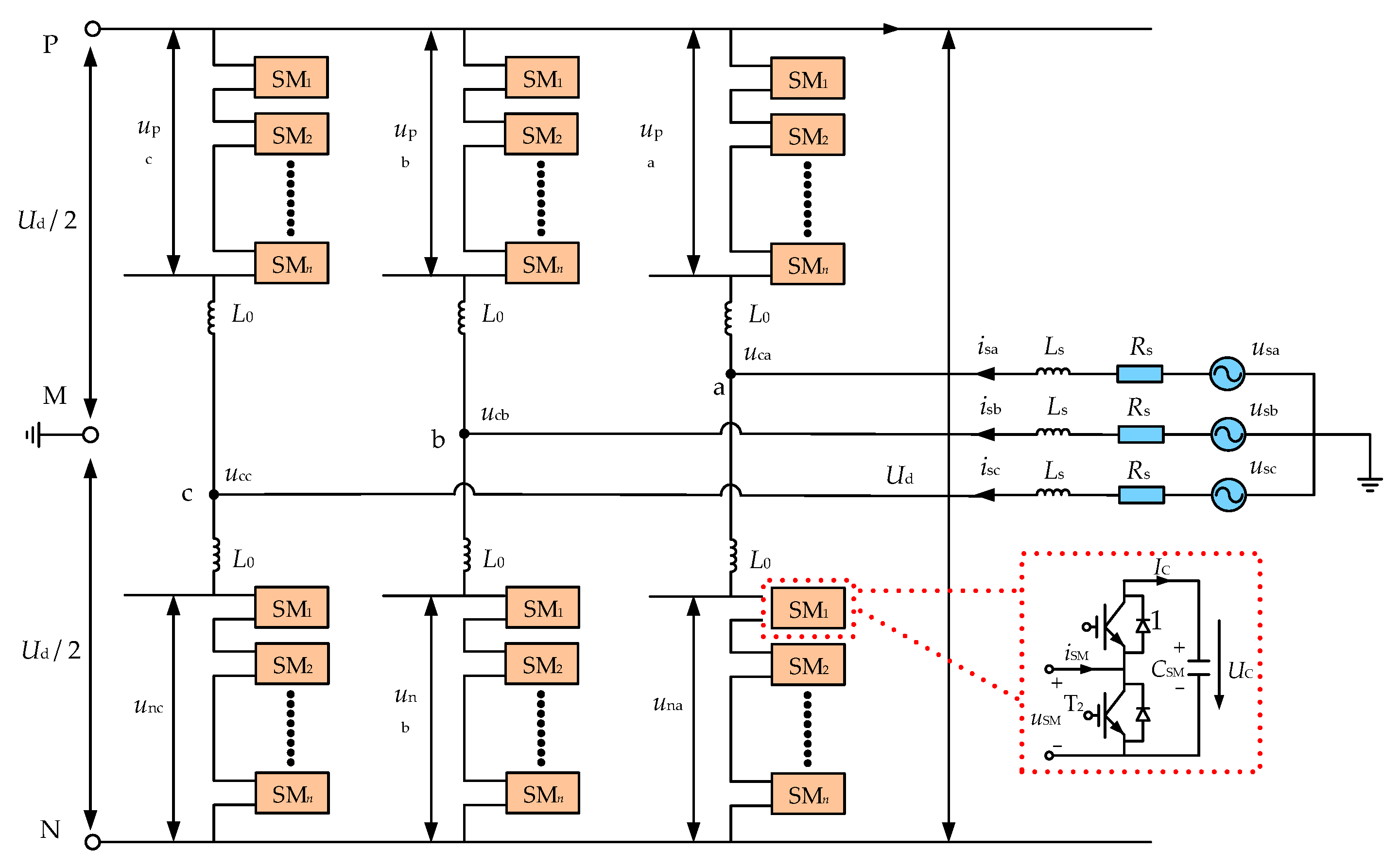
2. Model of Hybrid Hierarchical HVDC System

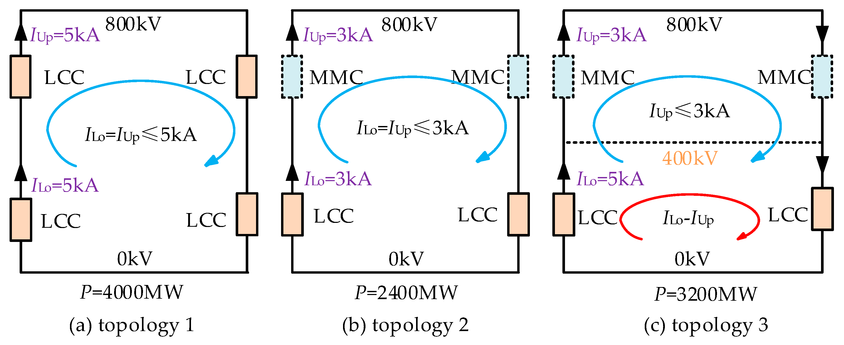
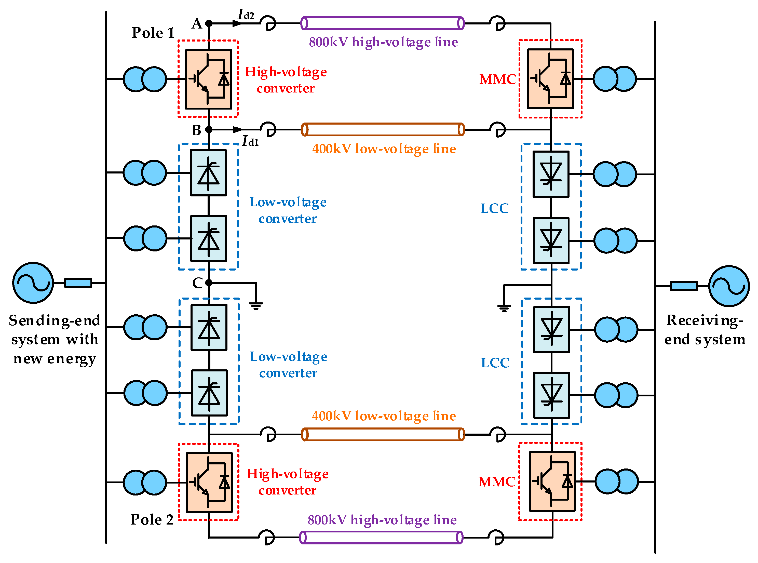
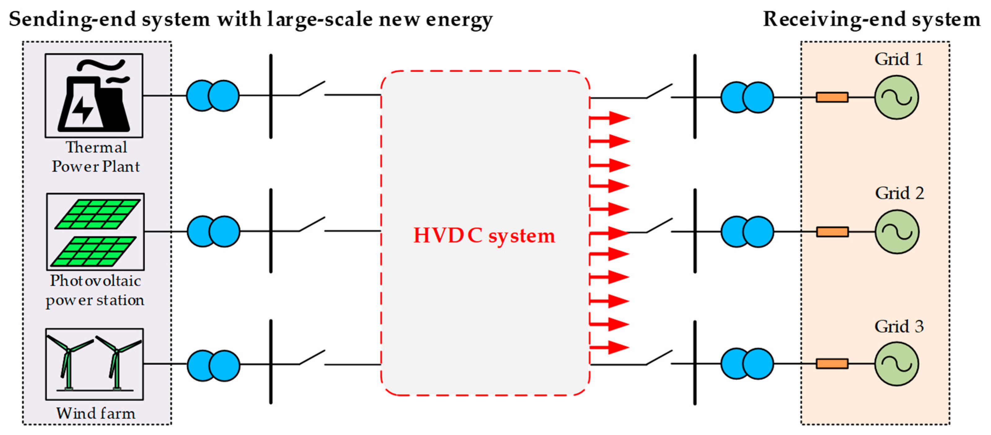
2.1. Selection of System Topology

To reduce transmission loss and increase transmission capacity, an HVDC with a high-voltage level of 800 kV or higher is utilized [25]. For the 800 kV HVDC system in topology 1 in Figure 2, the rated current of the LCC converter is set as 5 kA, so the DC power is 4000 MW. In consideration of the flexible transformation scheme for integration of new energy, the upper LCC converter is replaced with an MMC converter to form topology 2. Limited by the current capacity (3 kA) of MMC, the transmission power is reduced from the original 4000 MW to 2400 MW. If a 400 kV DC line is added in topology 2, topology 3 is established, and we can calculate that the transmission power of the hybrid HVDC system is improved from 2400 MW to 3200 MW.
For hybrid hierarchical HVDC, shown in Figure 3, hierarchical structure means that two DC lines are led out from point A at the high-voltage side and point B at the medium-voltage side, respectively. The 800 kV lines and 400 kV lines operate in parallel, and the system contains four DC lines. For ease of description, the converter between point A and point B on the rectifier side is called a high-voltage converter, and the converter between point B and point C is called a low-voltage converter. A 12-pulse LCC converter is adopted for the low-voltage converter, and an MMC converter is adopted for the high-voltage converter. The bipolar HVDC system is symmetrically equipped with the same converter stations.

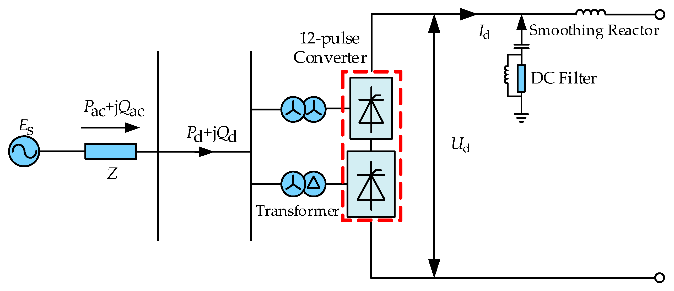
2.2. LCC and VSC Station

The low-voltage converter in Figure 3 adopts a 12-pulse converter. The quasi-steady mathematical model of the LCC converter is shown in Figure 4. The formulas of the mathematical model are as follows:
U d = 2.7 E r cos α 6 π X d I d
I d = E r 2 X d cos α cos α + μ
P d = U d I d
Q c = P d tan φ
where Er is the effective value of line voltage at the rectifier valve side. Ud is the DC voltage, Id is the DC current, and Pd is the DC power. Qc is the reactive power absorbed by the converter, and Xd is the commutation reactance in phase. ϕ is the power factor angle. α is the trigger delay angle, and µ is the commutation overlap angle.
For the high-voltage converter in Figure 3, VSC is adopted. As shown in Figure 5, the VSC converter includes six bridge arms, and each bridge arm is equipped with n sub-modules (SMs). The on, off or locking state of SMs is judged by the on/off signal state of switch T1/T2.
According to Figure 5, the mathematical model of VSC is described as:
L s d i sa d t = u s a R s i s a u c a L s d i sb d t = u s b R s i s b u c b L s d i sc d t = u s c R s i s c u c c
where ucm (m = a, b, c) is the electromotive force in VSC. usm (m = a, b, c) is the network-side voltage, and ism (m = a, b, c) is the network-side current. Ls and Rs are the equivalent inductance and equivalent resistance of the VSC station, respectively.

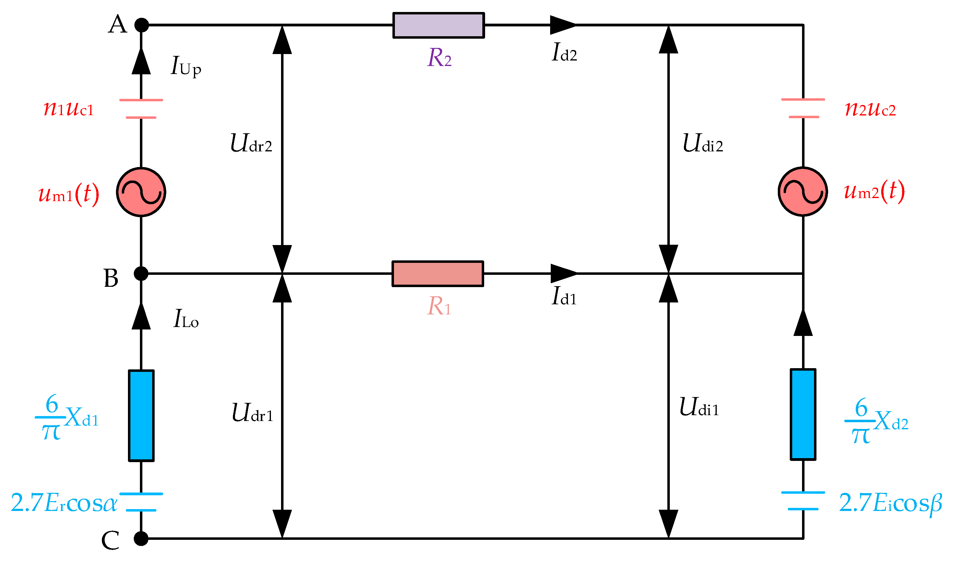
2.3. System Equivalent Circuit

Since a hybrid hierarchical HVDC system contains LCC and VSC converters, it is necessary to establish the system equivalent circuit to study the coordinated control strategy. As pole 1 and pole 2 operate symmetrically, we choose pole 1 as the research object. According to the mathematical models of LCC and VSC, the simplified equivalent circuit of hybrid hierarchical HVDC is established.
In Figure 6, α1 is the trigger delay angle of LCC at the rectifier side, and β2 is the trigger advance angle of LCC at the inverter side. Xd1 and Xd2 are the commutation reactance of the rectifier and inverter station, respectively. Um1(t) represents the sum of unbalanced voltage and voltage change of bridge arm reactor caused by charging or discharging of the sub-module in the rectifier-side MMC. Um2(t) represents the sum of unbalanced voltage and voltage change of bridge arm reactor caused by charging or discharging of the sub-module in the inverter-side MMC. R1 and R2 are the equivalent resistances of 400 kV and 800 kV DC lines, respectively. Id1 and Id2 are the DC current of 400 kV and 800 kV lines, respectively. IUp and ILo are the DC current of the high-voltage and low-voltage converters, respectively. Udr1 and Udi1 are the DC voltage of the rectifier-side LCC and inverter-side LCC, respectively. Udr2 and Udi2 are the DC voltage of the rectifier-side MMC and the inverter-side MMC, respectively.
Thus, the steady-state mathematical model of hybrid hierarchical HVDC system is established as:
U dr = U dr 1 + U dr 2 2.7 E r cos α 1 6 π X d 1 I d 1 + I d 2  +  n 1 u c 1
U di = U di 1 + U di 2 2.7 E i cos β 2 6 π X d 2 I d 1 + I d 2  +  n 2 u c 2
I d 1  =  U dr 1 U di 1 / R 1
I d 2  =  U dr 2 U di 2 / R 2
P r = U dr 1 I d 1 + I d 2  +  U dr 2 I d 2
P i = U di 1 I d 1 + I d 2  +  U di 2 I d 2
where N1 and N2 are the number of sub-modules of the MMC converter at the rectifier side and inverter side, respectively. uc1 and uc2 are the voltage of a single sub-module of the MMC converter at the rectifier and inverter, respectively. Pr and Pi are the active power of the rectifier and inverter, respectively.

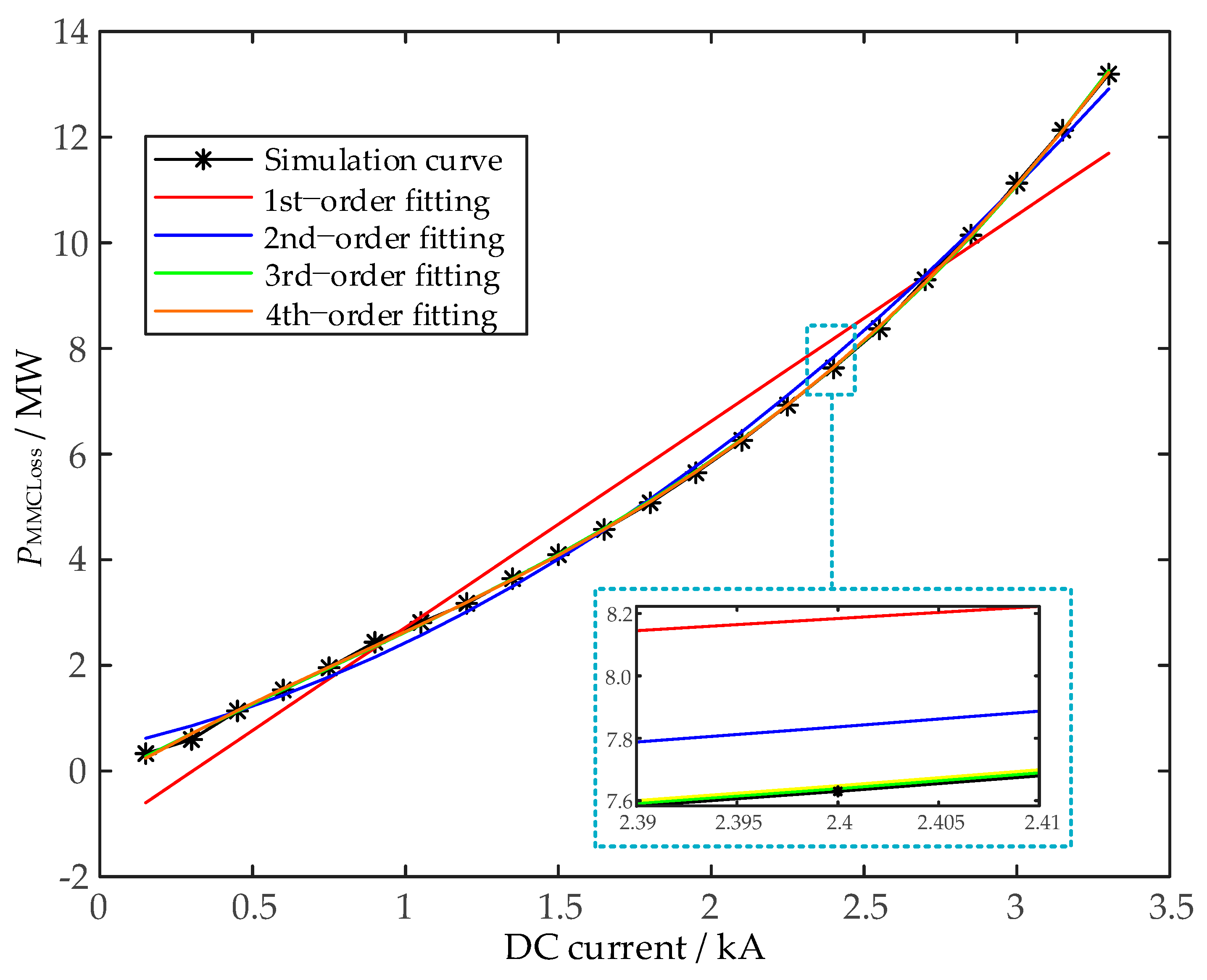
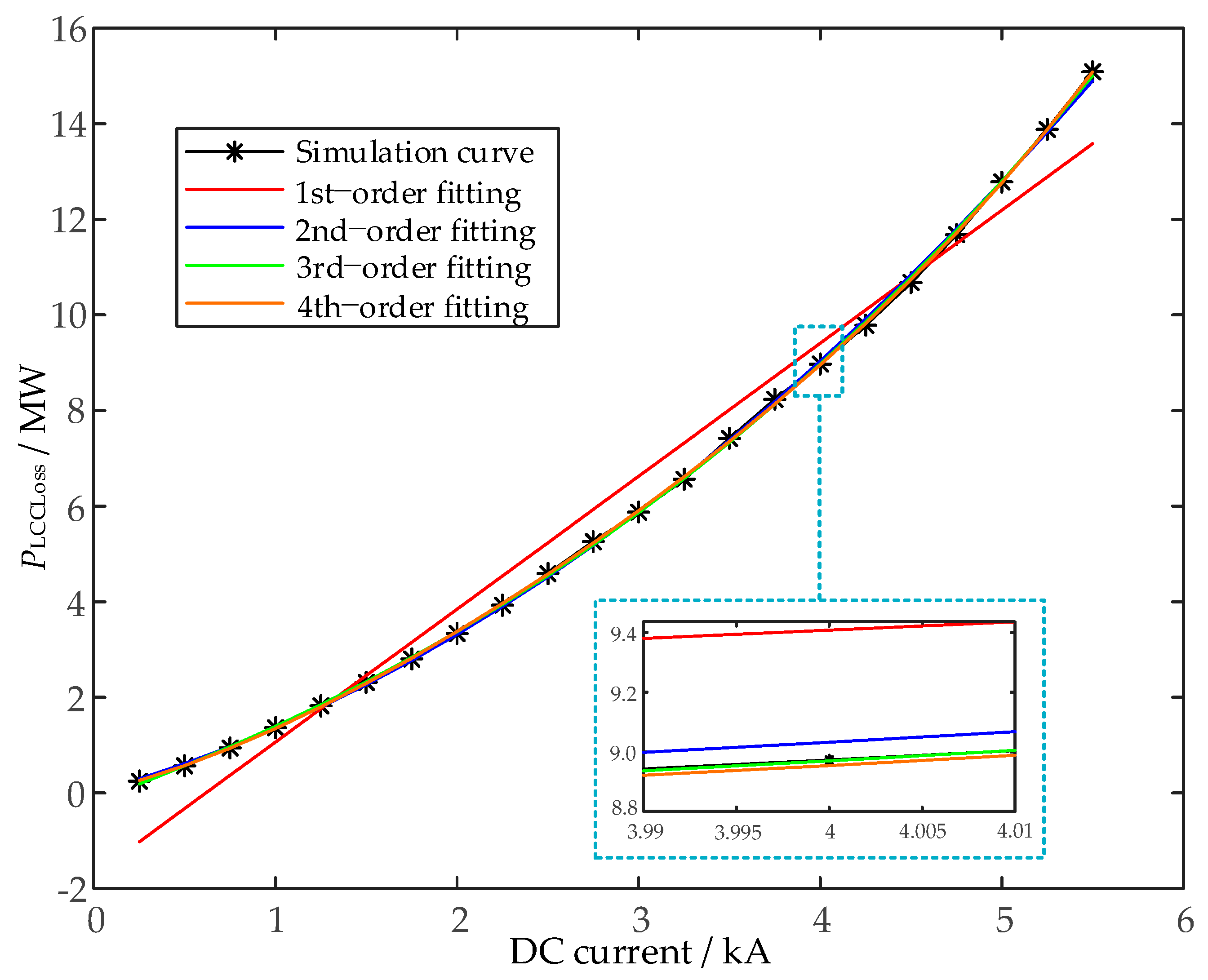
3. HVDC Transmission Loss Model Based on Multi-Order Fitting Method

To lower the cost of the HVDC system, transmission loss is an important assessment factor, mainly including LCC station loss, MMC station loss and DC line loss.

3.1. Loss Model of LCC Station

The loss model of the LCC station involves a converter valve, converter transformer, smoothing reactor and AC filter. Among them, the converter valve and converter account for more than 85% of the total loss. The specific formulas of various equipment losses are described specifically in existing references. To facilitate the objective optimization, the loss model of the LCC converter station can be expressed as:
P LCCLoss = a n I d n + a n 1 I d n 1 + + a 1 I d + a 0
where PLCCLoss is the loss of LCC station. Id is DC current of the LCC converter. an, …, a1, a0 are the loss coefficients. n is the order of the fitting polynomial.
Based on the CIGRE model, the rated DC voltage UdN of the LCC converter station is set as 400 kV and the rated DC current IdN is 5.0 kA by selecting 22 operation data between [0, 1.1 p.u.] in the simulation model, and using the multi-order fitting method to fit this group of data. The 1st-order, 2nd-order, 3rd-order and 4th-order fitting functions are shown in Figure 7. According to the error analysis, the fitting effect of the 4th-order fitting function is the best. Therefore, the LCC loss model adopts the 4th-order fitting function.

3.2. Loss Model of MMC Station

The loss model of the MMC station involves a converter valve, converter transformer and smoothing reactor. Among them, the converter valve and converter account for more than 80% of the total loss. Reference [19] studies the loss of a 201-level MMC under frequency conditions from 50 to 1000 Hz. The detailed loss model and loss approximate model are adopted, respectively, and the calculation error is less than 6%. The loss approximation model characterizes the quadratic relationship between the MMC converter station and current. In order to improve the fitting effect, the approximate expression of the MMC loss is established as:
P MMCLoss = b n I d n + b n 1 I d n 1 + + b 1 I d + b 0
where PMMCLoss is the loss of MMC station. Id is the DC current of the MMC converter. bn, …, b1, b0 are the loss coefficients. n is the order of the fitting polynomial.
Similarly, referring to the multi-order fitting method of the LCC converter station, the detailed MMC model is traversed and simulated to determine the fitting order of the MMC converter station loss model. As shown in Figure 8, according to the error analysis, the fitting effect of the 4th-order polynomial function is the best, so the MMC loss model adopts the 4th-order fitting function.

3.3. Loss Model of Transmission Line

Since the corona loss of the DC line is small and negligible, only the resistance loss is considered. The expression of the DC Line is:
P LineLoss = P L 1 Loss + P L 2 Loss = R 1 I d 1 2 + R 2 I d 2 2
where PLineLoss is the total loss of DC lines. PL1Loss and PL2Loss are the loss of the 400 kV and 800 kV DC lines, respectively.

3.4. Loss Model of Hybrid Hierarchical HVDC

Based on the above analysis, the loss function of the hybrid hierarchical HVDC including the LCC converter station loss, MMC converter station loss and DC line loss is established as:
P Loss = P LCCLoss + P MMCLoss + P LineLoss = i = 1 N 1 P LCC i Loss + j = 1 N 2 P MMC j Loss + p = 1 N 3 P Line p Loss
where N1, N2, N3 are the number of LCC converter stations, MMC converter stations and DC lines, respectively. PLCCiLoss is the loss of the LCC station i. PMMCjLoss is the loss of the MMC station j. PLinepLoss is the loss of the DC line p.

4. Current Allocation Strategy considering Multi-Objective Optimization Method

Due to the different resistance values of the high-voltage and low-voltage DC lines, and the loss difference between the LCC station and the MMC station, the same rated current command configuration method for high-voltage and low-voltage converters is unsuitable in the proposed topology. Therefore, considering the perspective of transmission loss reduction and voltage deviation optimization of key nodes, the constant active power controller of the high-voltage converter and the constant current controller of the low-voltage converter are designed based on the optimal current allocation strategy. The strategy introduces the hybrid HVDC loss function and voltage deviation function of the key node, and utilizes a multi-objective genetic algorithm and maximum satisfaction method to determine the optimal compromise value of the DC current for high-voltage and low-voltage converters, so as to ensure the coordinated control and economy of the proposed HVDC system.

4.1. Multi-Objective Optimization Model

A hybrid hierarchical HVDC system includes multiple converter stations and multiple DC lines. Combined with each loss model, the objective function F1 is determined, and the objective function F2 is determined by considering the minimum voltage deviation of key nodes. The multi-objective optimization model can be expressed as:
F 1 = P Loss = i = 1 N 1 P LCC i Loss + j = 1 N 2 P MMC j Loss + p = 1 N 3 P Line p Loss F 2 = m = 1 N U m U m N
where Um and UmN are the actual voltage values and the rated voltage values of the key node j, respectively. N is the number of key nodes.
Active power, DC current, and key node voltage are selected as constraints:
P ref = U dr 1 I d 1 + I d 2  +  U dr 2 I d 2 0 I d 1 I 1 max , 0 I d 2 I 2 max 0 I d 1 + I d 2 I LCCmax 1 k U m N U m  ≤  1 + k U m N
where PLoss is the total loss of HVDC. I1max and I2max are the maximum currents allowed for the 400 kV line and 800 kV lines, respectively. Pref is the rated power. ILCCmax is the maximum current of the LCC. k is the node voltage deviation coefficient.

4.2. Optimal Current Allocation Strategy Based on Multi-Objective Genetic Algorithm

After the Pareto solution set of the optimization model is obtained by a multi-objective genetic algorithm, the optimal compromise values of the DC current (Id1opt and Id2opt) need to be selected according to the operation of the hybrid hierarchical HVDC system. In this paper, the maximum satisfaction method is considered in [26]. The optimization function is Formula (16), and the optimization objective is to minimize the transmission loss and voltage deviation of the key node. Therefore, the partial small satisfaction function is used for the calculation, as shown in Formula (18). For the objective function corresponding to each optimal solution in the Pareto solution set of multi-objective genetic algorithms, the membership function is used to calculate its satisfaction. After standardization, the solution with the largest satisfaction value is the optimal compromise value of the DC current in Formula (19).
μ n i = 1 , f n f n min f n max  -  f n f n max  -  f n min , f n max f n f n min 0 , f n f n max
where fn is the value of the nth objective. fnmin and fnmax are the minimum and maximum values in the Pareto solution set, respectively.
μ i = n = 1 N μ n i i = 1 M n = 1 N μ n i
where μi is the standardized satisfaction of the ith optimal solution. M is the number of Pareto optimal solutions, and N is the total number of objective functions.
After determining the optimal values Id1opt and Id2opt of the DC current, we calculate the active power order of the high-voltage MMC converter (PRef_Up) and the DC current order of the low-voltage LCC converter (ILCC_Lo) according to Formulas (20) and (21):
P Ref _ Up = I Ref _ Up U dr 2 = I d 2 opt U dr 2
I Ref _ Lo = I d 1 opt + I d 2 opt
Based on the optimal current allocation model for the high-converter and the low-voltage converter, the constant active power controller of the high-voltage converter and the constant current controller of the low-voltage converter are designed, as shown in Figure 9. Firstly, the input parameters are the HVDC power order Pref, rectifier DC voltage Udc, voltage deviation coefficient k, etc. The DC current order of the high-voltage MMC converter (IRef_Up) and the low-voltage LCC converter (IRef_Lo) are obtained through the multi-objective optimization model considering the optimization of the hybrid HVDC transmission loss and voltage deviation. The active power order PRef_Up is obtained according to Formula (15) and then put into the outer loop of the constant active power controller for the high-voltage converter. The measured current value of the LCC converter is compared with the reference value, and then βLCC_Up is obtained by PI modular. Finally, by subtracting βLCC_Lo, the trigger delay angle (αLCC_Lo) of the low-voltage LCC converter can be obtained.

5. Case Study

5.1. Results of Optimal Current Allocation Strategy

The resistance of the 400 kV line and the 800 kV line in the hierarchical HVDC system are 0.024 Ω/km and 0.018 Ω/km, respectively, and the length of the transmission line is 200 km. Due to the limitation of the current capacity, the maximum current capacity of the MMC converter and LCC converter are 3.125 kA and 5.45 kA, respectively. The DC voltage node, of which the DC voltage is greater than or equal to 400 kV, is regarded as the key node, and the transmission power of the single-pole system is 3000 MW. Based on the multi-objective optimization model, MATLAB is used for optimal calculation. Figure 10 shows the Pareto set result obtained by the multi-objective genetic algorithm.
According to Formulas (20) and (21), the maximum satisfaction method is used to obtain the optimal compromise value of the DC current. The optimal compromise command value of the DC current flowing through the high-voltage converter and the low-voltage converter is 3.12 kA and 4.38 kA, respectively. A total of 15 groups of typical data were taken for comparison, as shown in Table 1. U1’and U2’ represent the DC voltage of the low-voltage line and high-voltage line at the inverter side, respectively. With the increase in the DC current of the low-voltage line, the power loss decreases. When Id1 increases, the DC voltage of the high-voltage line at the inverter side increases. Compared with the traditional control method (No. 6 in Table 1), the proposed control method (No. 13 in Table 1) can reduce the transmission loss by 7.67% and the voltage deviation drops by 17.71%.

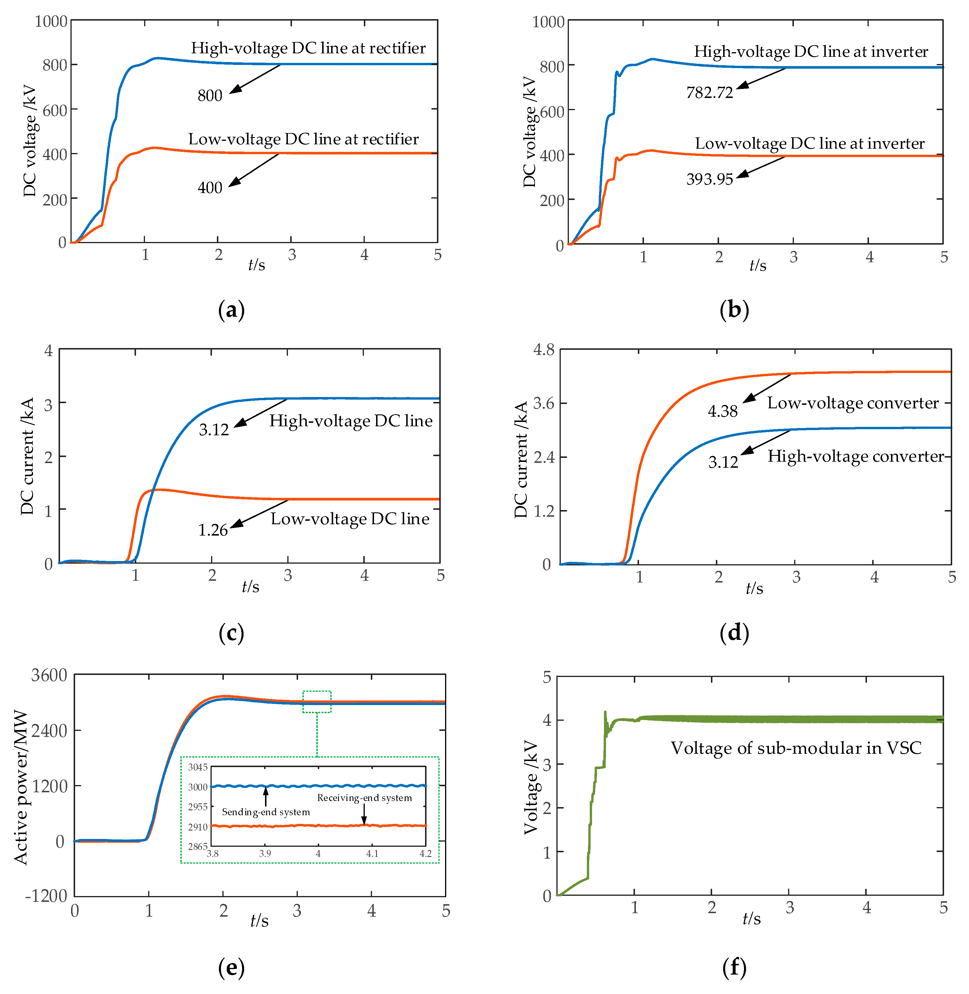
5.2. Steady Characteristics

The detailed electromagnetic transient model of the hybrid hierarchical HVDC system, shown in Figure 3, is constructed based on PSCAD software. The rectifier side adopts the 12-pulse converter model of the CIGRE standard system. The specific parameters are shown in the literature [27], and the basic operating parameters of the proposed HVDC system are shown in Table 2. According to the optimization results, the optimal current of the high-voltage MMC converter and the low-voltage LCC converter is 3.12 kA and 4.38 kA, respectively. The optimal current of the high-voltage DC line and the low-voltage DC line is 3.12 kA and 1.26 kA, respectively. The LCC converter on the rectifier side adopts the constant DC current control mode, and the MMC converter on the rectifier side adopts the constant active power and reactive power control method equipped with the optimal current allocation strategy proposed in this paper. The LCC converter on the inverter side adopts the constant DC voltage control mode, and the MMC converter on the inverter side adopts the constant DC voltage and reactive power control method.
The simulation time is set as 6 s for depicting the steady-state characteristics of the hybrid hierarchical HVDC with the high-voltage and low-voltage DC lines operating in parallel.
It can be seen from Figure 11 that the start-up process of the HVDC is relatively stable. On the rectifier side, the DC voltage of the high-voltage DC line and low-voltage DC line is 800 kV and 400 kV, respectively. On the inverter side, considering the voltage drop of the converter stations and DC lines, the high-voltage DC line can realize the power transmission of 782.72 kV and 3.12 kA, and the low-voltage DC line can realize the power transmission of 393.95 kV and 1.26 kA, according to Figure 11b,c. According to Figure 10, since the electrical power of the low-voltage converter flows into the high-voltage DC line and low-voltage DC line, the current of the low-voltage converter is 4.38 kA, while the DC current of the high-voltage converter is 3.12 kA. In Figure 11e, the active power of the sending-end system and the receiving-end system is 3000 MW and 2912.93 MW, respectively. The transmission loss is 87.07 MW, which is the result of the optimal allocation of high-voltage and low-voltage converters. During the stable operation, the voltage of SM is 4 kV, according to Figure 11f. The above simulation results verify the effectiveness of the optimal current allocation strategy. The coordination strategy can not only ensure the stable start-up of the system but also achieve the goal of minimizing transmission loss and reducing the withstand voltage requirements of converter devices.

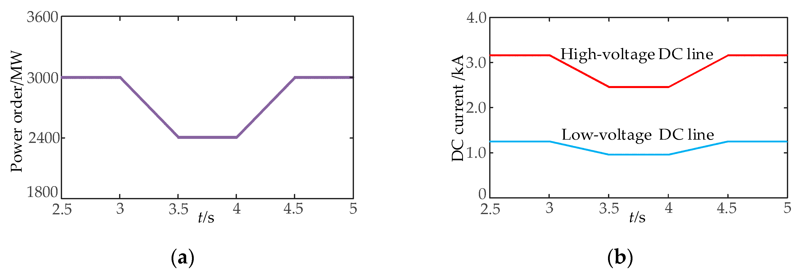
5.3. Step Characteristics

We set the active power command as 1.0 p.u. (3000 MW), and introduced an active power command module including three stages: (1) the initial power command is 1.0 p.u., and then drops to 0.8 p.u. from 3.0 to 3.5 s; (2) from 3.5 to 4.0 s, the power command remains unchanged; (3) from 4.0 to 4.5 s, the power recovers to 1.0 p.u. Figure 12 is the response result of the hybrid hierarchical HVDC under the variation of power command.
According to Figure 12, when the active power order issued by the active power command module decreases step by step from 3.0 s, the current commands of the high-voltage line and low-voltage line decrease accordingly. When the active power command increases at 4.0 s, the current command increases. At 4.5 s, the active power order recovers to 1.0 p.u., and the DC current fluctuates with the active power order rapidly. The DC voltage of the high-voltage DC line and low-voltage DC line at the inverter side is 782.72 kV and 393.95 kV, respectively. Therefore, the proposed HVDC system presents good response characteristics.

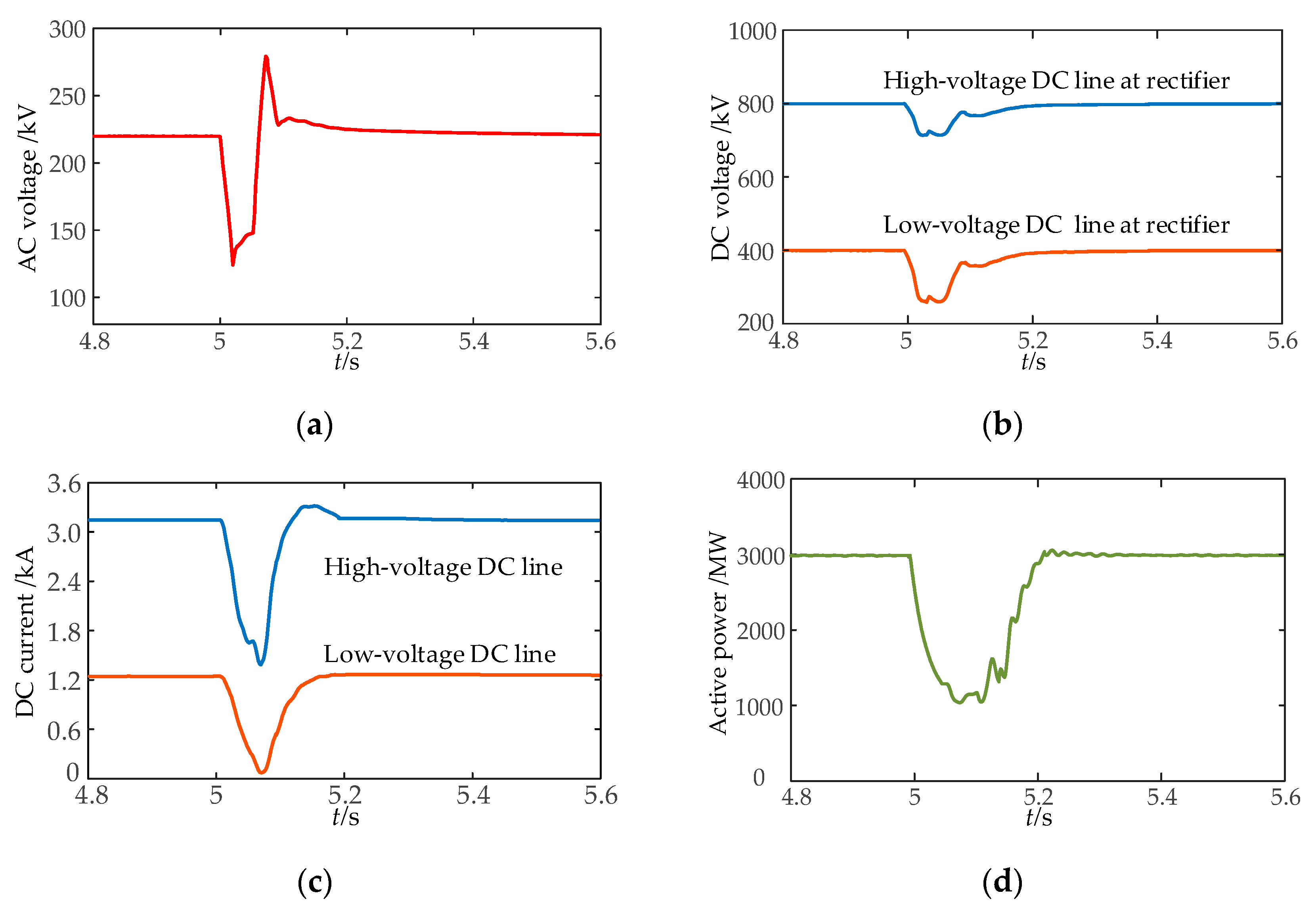
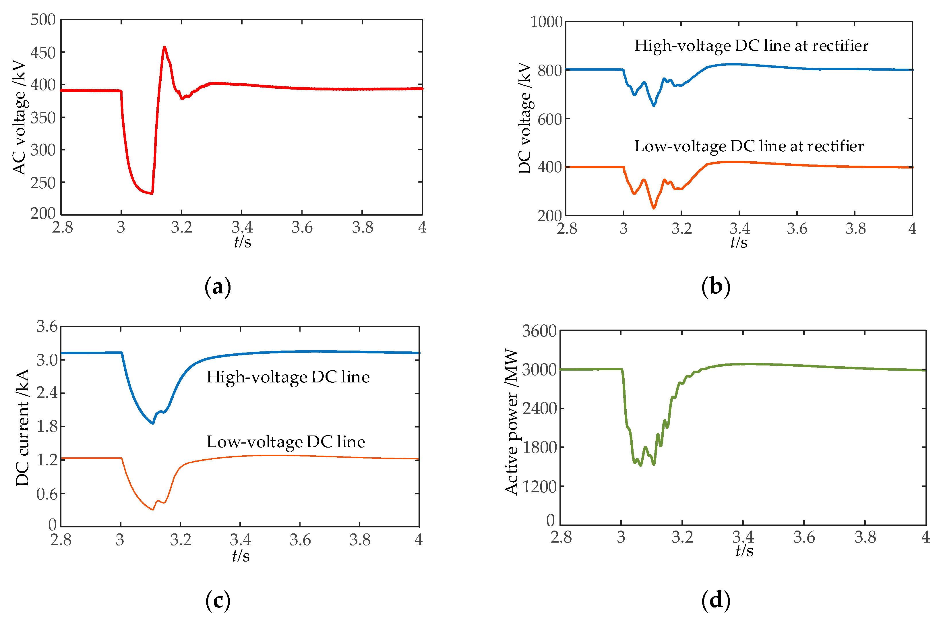
5.4. AC Fault at Rectifier Side

A three-phase fault occurs at the rectifier side in 3 s with a duration of 0.1 s, and the grounding resistance is 8 Ω. The simulation results are shown in Figure 13.
When the three-phase fault occurs in the sending-end system, as shown in Figure 13a, the AC system at the rectifier side drops to 60% of the normal value, and the DC parameters drop accordingly. In Figure 13b–d, the DC current of the transmission line drops greatly, the high-voltage DC line drops from 3.12 kA to 1.87 kA, the low-voltage DC line drops from 1.26 kA to 0.33 kA. The active power transmitted by the HVDC system decreases from 3000 MW to 1628 MW, which returns to the normal level after 0.33 s. Due to the regulating effect of the DC voltage regulator in the MMC, the drop range of the DC voltage is smaller than that of the DC current, and the rated voltage can be restored in a short time. Therefore, the optimal current allocation method of the hybrid hierarchical HVDC system can respond to the rectifier-side fault in time. Meanwhile, the DC current is always continuous without dropping to zero. After the fault is cleared, the system can quickly return to its normal operation state.

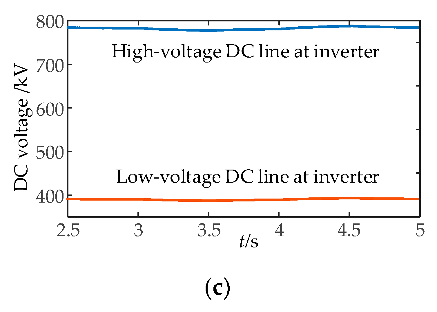
5.5. AC Fault at Inverter Side

A three-phase fault occurs at the inverter side in 5 s with a duration of 0.1 s, and the grounding resistance is 8 Ω. The simulation results are shown in Figure 14.
Figure 14a shows the voltage curve of the receiving-end system. When the three-phase fault occurs, the AC voltage at the inverter side drops from the rated value of 220 kV to 132 kV. Figure 14b–d depicts the curves of the DC voltage, DC current and active power during an inverter-side fault, respectively. The AC system fault on the inverter side causes the drop of the AC voltage amplitude and the power transmitted to the receiving-end system decreases. At this time, the MMC converter can activate its DC voltage regulation ability and provide reactive power support. Due to the mismatch of active power between the rectifier side and the inverter side, the unbalanced power enters the capacitance of the sub-module in the MMC, which further reduces the drop degree of the DC voltage. During the whole fault process, the system recovers quickly and returns to normal operation by 0.20 s. In the simulation scenario, there is no commutation failure that occurs in the inverter station. The DC current and voltage of the hybrid hierarchical HVDC system remain well-regulated during the AC fault, which depends on the optimal current allocation strategy.

6. Conclusions

This study proposes an optimal current allocation method for a hybrid hierarchical HVDC with several DC lines with different voltage grades. By considering the current capacity difference between LCC and VSC, the hybrid hierarchical HVDC scheme, with parallel operation of 400 kV and 800 kV DC lines, is designed for massive energy transmission. We establish the multi-order fitting function of transmission loss including LCC converter stations, MMC converter stations and DC lines. The current optimal allocation strategy based on a multi-objective genetic algorithm is proposed to form an improved constant current controller suitable for the proposed HVDC topology to realize the stable operation goal of the high-voltage and low-voltage converters. The transient-state and steady-state characteristics are verified in the PSCAD simulation. According to the simulation results, the current optimal allocation strategy has better performance for reducing HVDC transmission loss by 7.67% and dropping voltage deviation by 17.71% compared to the traditional control method.
The following works will focus on a detailed station loss model considering multiple operating conditions of converter valves and the transient coordinated control strategy of the HVDC system with the integration of massive renewable energy.

Author Contributions

Conceptualization: Z.Y., B.G. and Z.C.; validation: Z.Y. and Z.C.; investigation: Z.Y. and B.G.; methodology: Z.Y.; original draft: Z.Y.; writing—review and editing: Z.Y. and B.G. All authors have read and agreed to the published version of the manuscript.

Funding

This research received no external funding.

Institutional Review Board Statement

Not applicable.

Informed Consent Statement

Not applicable.

Data Availability Statement

The data presented in this study are available in the article.

Conflicts of Interest

The authors declare no conflict of interest.

Nomenclature

General and Abbreviation
HVDCHigh-voltage direct current.
HVACHigh-voltage alternative current.
LCCLine commutated converter.
VSCVoltage source converter.
DCDirect current.
kVKilovolt.
GWGigawatt.
MWMegawatt.
MMCModular multilevel converter.
SMSub-module.
EEffective value of line voltage.
UDC voltage.
IDC current.
PActive power.
QReactive power.
XCommutation reactance.
αTrigger delay angle of LCC.
βTrigger advance angle of LCC.
LEquivalent inductance.
REquivalent resistance.
PSCADPower systems computer-aided design.
Subscripts
a, b, cQuantities of a, b and c-phase.
r, iQuantities of rectifier and inverter side.
max, minQuantities of maximum and minimum.
Ref_UpQuantity of high-voltage converter.
Ref_LoQuantity of low-voltage converter.

References

  1. Wang, M.; An, T.; Ergun, H.; Lan, Y.; Andersen, B.; Szechtman, M.; Leterme, W.; Beerten, J.; Hertem, D.V. Review and Outlook of HVDC Grids as Backbone of Transmission System. CSEE J. Power Energy Syst. 2021, 7, 797–810. [Google Scholar]
  2. Luo, X.; Li, F.; Fan, L.; Niu, T.; Li, B.; Tian, L.; Yu, H. Influence of Synchronous Condensers on Operation Characteristics of Double-Infeed LCC-HVDCs. Processes 2021, 9, 1704. [Google Scholar] [CrossRef]
  3. Ayobe, A.S.; Gupta, S. Comparative Investigation on HVDC and HVAC for Bulk Power Delivery. Mater. Today Proc. 2022, 19, 958–964. [Google Scholar] [CrossRef]
  4. The International Renewable Energy Agency (IRENA). Renewable Capacity Statistics 2021. Available online: https://www.irena.org/publications/2021/March/Renewable-Capacity-Statistics-2021 (accessed on 1 March 2021).
  5. Wang, J.; Huang, M.; Fu, C.; Li, H.; Xu, S.; Li, X. A New Recovery Strategy of HVDC System during AC Faults. IEEE Trans. Power Del. 2019, 34, 486–495. [Google Scholar] [CrossRef]
  6. Liang, X.; Mehdi, A. HVDC Transmission and Its Potential Application in Remote Communities: Current Practice and Future Trend. IEEE Trans. Ind. Appl. 2022, 58, 1706–1719. [Google Scholar] [CrossRef]
  7. Sang, Y.; Yang, B.; Shu, H.; An, N.; Yu, T. Fault Ride-Through Capability Enhancement of Type-4 WECS in Offshore Wind Farm via Nonlinear Adaptive Control of VSC-HVDC. Processes 2019, 7, 540–561. [Google Scholar] [CrossRef] [Green Version]
  8. Zhao, Z.; Iravani, M.R. Application of GTO Voltage Source Inverter in a Hybrid HVDC Link. IEEE Trans. Power Del. 1994, 9, 369–377. [Google Scholar] [CrossRef]
  9. Chang, Y.; Cai, X. Hybrid Topology of a Diode-Rectifier-Based HVDC System for Offshore Wind Farms. IEEE Trans. Emerg. Sel. Topics Power Electron. 2019, 7, 2116–2128. [Google Scholar] [CrossRef]
  10. Bakas, P.; Okazaki, Y.; Shukla, A.; Patro, S.K.; Nami, A. Review of Hybrid Multilevel Converter Topologies Utilizing Thyristors for HVDC Applications. IEEE Trans. Power Electron. 2021, 36, 174–190. [Google Scholar] [CrossRef]
  11. Xiao, H.; Sun, K.; Pan, J.; Li, Y.; Liu, Y. Review of Hybrid HVDC Systems Combining Line Communicated Converter and Voltage Source Converter. Int. J. Electr. Power Energy Syst. 2021, 129, 1–9. [Google Scholar] [CrossRef]
  12. Li, Z.; He, Y.; Li, Y.; Gu, W.; Tang, Y.; Zhang, X.P. Hybrid Control Strategy for AC Voltage Stabilization in Bipolar VSC-MTDC. IEEE Trans. Power Syst. 2019, 34, 129–139. [Google Scholar] [CrossRef]
  13. Lee, G.; Hwang, P.I.; Moon, S.I. Reactive Power Control of Hybrid Multi-Terminal HVDC Systems Considering the Interaction Between the AC Network and Multiple LCCs. IEEE Trans. Power Syst. 2021, 36, 4562–4574. [Google Scholar] [CrossRef]
  14. Chen, X.; Li, H.; Wang, G.; Xu, C.; Liang, Y. A Convolution Power-Based Protection Scheme for Hybrid Multiterminal HVDC Transmission Systems. IEEE Trans. Emerg. Sel. Topics Power Electron. 2021, 9, 1655–1667. [Google Scholar] [CrossRef]
  15. Ni, X.; Gole, A.M.; Zhao, C.; Guo, C. An Improved Measure of AC System Strength for Performance Analysis of Multi-Infeed HVdc Systems Including VSC and LCC Converters. IEEE Trans. Power Del. 2018, 33, 169–178. [Google Scholar] [CrossRef]
  16. Zhu, J.; Li, S.; Yu, L.; Bu, S.; Li, Y.; Deng, Z.; Wang, Y.; Jia, H.; Wang, C.; Liu, D. Coherence Analysis of System Characteristics and Control Parameters for Hybrid HVDC Transmission Systems Based on Small-Signal Modeling. IEEE Trans. Emerg. Sel. Topics Power Electron. 2021, 9, 7436–7446. [Google Scholar] [CrossRef]
  17. He, Y.; Xiang, W.; Ni, B.; Lu, X.; Wen, J. Impact of Strength and Proximity of Receiving AC Systems on Cascaded LCC-MMC Hybrid HVDC System. IEEE Trans. Power Del. 2021, 1. [Google Scholar] [CrossRef]
  18. Sreedevi, J.; Manohar, P.; Aradhya, R. Dynamic Performance of Hybrid Multiinfeed HVDC System on RTDS. In Proceedings of the Eighteenth National Power Systems Conference (NPSC), Guwahati, India, 18–20 December 2014. [Google Scholar]
  19. Guo, C.; Wang, Y.; Li, J.; Zhao, C.; Fu, C. Design and Development of Experimental Platform for Hybrid HVDC System. High Volt. Eng. 2019, 45, 3157–3163. [Google Scholar]
  20. Xiao, H.; Duan, X.; Zhang, Y.; Li, Y. Analytically Assessing the Effect of Strength on Temporary Overvoltage in Hybrid Multi-Infeed HVDC Systems. IEEE Trans. Power Electron. 2022, 37, 2480–2484. [Google Scholar] [CrossRef]
  21. Cheng, F.; Yao, L.; Xu, J.; Chi, Y.; Sun, Y.; Wang, Z.; Li, Y. A new AC Fault Ride-through Strategy for HVDC Link with Serial Connected LCC-VSC Hybrid Inverter. CSEE J. Power Energy Syst. 2022, 8, 175–187. [Google Scholar]
  22. Liu, Y.; Luo, G.; Yang, Y.; Zhang, X.; Yang, L. Adaptability Analysis of Traveling Wave Protection in Multi-terminal Hybrid DC Transmission Lines. In Proceedings of the 2020 4th International Conference on HVDC (HVDC), Xi’an, China, 6–9 November 2020. [Google Scholar]
  23. Hou, J.; Song, G.; Chang, P.; Xu, R.; Hussain, K. Fault Identification Scheme for Hybrid Multi-terminal HVDC System Based on Control and Protection Coordination Strategy. Int. J. Electr. Power Energy Syst. 2022, 136, 1–13. [Google Scholar] [CrossRef]
  24. Guo, C.; Wu, Z.; Yang, S.; Hu, J. Overcurrent Suppression Control for Hybrid LCC/VSC Cascaded HVDC System Based on Fuzzy Clustering and Identification Approach. IEEE Trans. Power Del. 2021, 1. [Google Scholar] [CrossRef]
  25. Qin, Y.; Wen, M.; Yin, X.; Bai, Y.; Fang, Z. Comprehensive Review of Commutation Failure in HVDC Transmission Systems. Electr. Power Syst. Res. 2022, 205, 1–10. [Google Scholar]
  26. Farina, M.; Amato, P. A Fuzzy Definition of “Optimality” for Many-criteria Optimization Problem. IEEE Trans. Syst. Man Cybern. A Syst. Hum. 2004, 34, 315–326. [Google Scholar] [CrossRef]
  27. Ouyang, J.; Zhang, Z.; Li, M.; Pang, M.; Diao, Y. A Predictive Method of LCC-HVDC Continuous Commutation Failure Based on Threshold Commutation Voltage under Grid Fault. IEEE Trans. Power Syst. 2021, 36, 118–126. [Google Scholar] [CrossRef]
Figure 1. New energy power system via HVDC.
Processes 10 00579 g001
Figure 2. Comparison for different HVDC topologies.
Processes 10 00579 g002
Figure 3. Structure of hybrid hierarchical HVDC system.
Processes 10 00579 g003
Figure 4. Schematic diagram of 12-pulse LCC converter.
Processes 10 00579 g004
Figure 5. Schematic diagram of VSC.
Processes 10 00579 g005
Figure 6. Equivalent circuit of simplified system.
Processes 10 00579 g006
Figure 7. Loss fitting curve of LCC station.
Processes 10 00579 g007
Figure 8. Loss fitting curve of MMC station.
Processes 10 00579 g008
Figure 9. Improved HVDC control based on optimal current allocation.
Processes 10 00579 g009
Figure 10. Result of multi-objective genetic algorithm.
Processes 10 00579 g010
Figure 11. Steady-state waveform of the proposed system. (a) DC voltage at rectifier side. (b) DC voltage at inverter side. (c) DC current of transmission line. (d) DC current of converter. (e) Active power of HVDC. (f) DC voltage of sub-module in VSC.
Processes 10 00579 g011
Figure 12. Response under system power command. (a) Power command of system. (b) DC current of transmission line. (c) DC voltage of system at the inverter side.
Processes 10 00579 g012aProcesses 10 00579 g012b
Figure 13. Waveform diagram under fault at rectifier side. (a) AC voltage at rectifier side. (b) DC voltage at rectifier side. (c) DC current of transmission line. (d) Active power of system.
Processes 10 00579 g013
Figure 14. Waveform diagram under fault at inverter side. (a) AC voltage at inverter side. (b) DC voltage at rectifier side. (c) DC current of transmission line. (d) Active power of system.
Processes 10 00579 g014
Table 1. Comparison of power loss and voltage variation.
NumberId1(kA)Id2(kA)PLoss(MW)U1’ (kV)U2’ (kV)
15.4502.050112.38383.68776.30
25.4002.100109.84384.16776.60
35.3002.200105.16385.12777.20
45.2002.300101.01386.08777.80
55.1002.40097.39387.04778.40
65.0002.50094.30388.00779.00
74.9002.60091.75388.96779.60
84.8002.70089.73389.92780.20
94.7002.80088.24390.88780.80
104.6002.90087.28391.84781.40
114.5003.00086.87392.80782.00
124.4003.10086.98393.76782.60
134.3803.12087.07393.95782.72
144.3753.12587.10394.00782.75
154.3003.20087.63394.72783.20
Table 2. Basic operating parameters of proposed system.
ParametersRectifierInverter
AC voltage/kV380220
Rated capacity/MW30003000
DC voltage/kV800782.72
Converter typeLCCMMC
Number of sub-modules/100
Transformer ratio380/172161/220
Publisher’s Note: MDPI stays neutral with regard to jurisdictional claims in published maps and institutional affiliations.

