Abstract
To study the influence of filling step and advancing distance on the deformation and failure of a working face floor, a mechanical model based on elastic foundation beam theory is established. The deflection and bending moment curves of the floor under different filling steps and advancing distance are obtained by Maple. Then, a fluid–solid coupling model of paste-filling mining on confined water is established by FLAC3D. The effects of different filling steps and advancing distance on the floor displacement, stress, and plastic zone of the floor are analyzed. The results show that there is a “concave” quadratic relationship between the filling step and the maximum displacement of the floor, and there is a “convex” quadratic relationship between the advancing distance and the maximum displacement of the floor. The maximum stress of the floor increases linearly with the increase in filling distance and tends to be stable with the increase in advancing distance. Moreover, the increase in filling steps will lead to the continuous increase in longitudinal failure. This study could guide paste-filling mining above confined water.
1. Introduction
With the extension of the mining depth of coal resources in China, water inrush from the coal mine floor is becoming more serious [1]. In this case, the problem of safe mining above confined water needs to be solved urgently [2]. Therefore, relevant researchers have carried out a series of studies on the failure characteristics and laws of the floor on confined water [3,4]. The “Key layer theory” is proposed, and then, the water inrush criterion of stope floor is established [5]. The theory of “original rock tension fracture” and “zero failure” further analyzes the maximum failure depth of the mining floor [6,7]. The theory of “strong seepage channel” shows that whether water inrush occurs in the floor is based on the water inrush channel [8,9]. The “rock water stress relationship” means that the water inrush was the result of the joint action of rock, water, and stress [10,11]. The “dominant surface” theory of water inrush shows that the coal-bearing stratum is the key to control floor stability [12,13,14,15,16]. In another aspect, with the accelerated development of urban underground resources and the massive construction of traffic engineering over the world, more traffic tunnels and underground engineering have been built with the characteristic of high water pressure alongside complex geological structures such as fault fracture zones, water inrush areas, weak rock mass status, etc. Facing these challenges, many scholars have conducted a considerable amount of research on reducing economic losses, injuries, and deaths and have obtained abundant and beneficial research results [17,18,19,20,21].
The parameters affecting the floor stability of paste-filling face mainly include filling strength, filling rate, filling step, etc. Relevant researchers have conducted a series of studies on the floor failure of paste filling on confined water [22,23,24,25,26]. Some researchers have analyzed the influencing factors of floor failure in paste-filling face from the perspective of filling strength and filling rate [27,28]. Many researchers analyzed the relationship between floor failure depth and mining height [29,30,31]. Previous studies have established the evaluation formula of paste-filling floor and the relationship between safety factor and filling parameters [32,33]. However, the effects of filling step, advancing distance, and floor failure on floor stability have not been studied thoroughly.
Therefore, taking the paste-filling mining project on confined water in the 11,607 areas of the working face of the Daizhuang coal mine as the background, this paper focuses on analyzing the deformation characteristics and failure of the floor under different filling steps and advancing distance. The research results will help to understand the mine floor water prevention. It is also the development and supplement of filling mining theory.
2. Project Overview
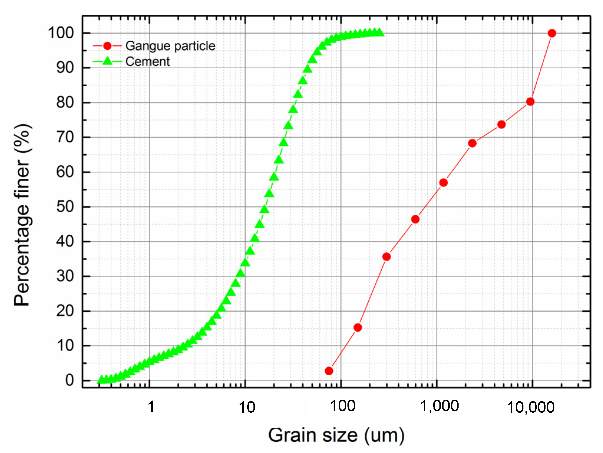
The Daizhuang coal mine is located in the north of the Jining coalfield. According to the characteristics of the water inrush properties in different areas of 1160 mining areas, the mine puts forward a regional paste-filling mining scheme to solve the problem. The paste-filling mining method is adopted. Generally, solid wastes such as gangue and construction waste are processed and crushed, mixed with cement and water, stirred into paste slurry without critical flow rate and bleeding, and then transported to the filling site by self-weight or pump pressure. In this project, the water and solid content of fill material are about 20% and 80%, respectively. The particle size distribution curve of fill materials is given in Figure 1.

Figure 1.
The distribution of the particles of filling materials.
The average buried depth of the 11,607 areas of the working face is 543 m. No. 16 coal is mainly mined. The average thickness of the coal seam is 2 m, and the average inclination angle is 7°. The aquifers have a great impact on its mining, which includes 13th ash and Ordovician ash. The upper boundary of the 13th ash aquifer is 24 m away from the coal seam floor, and the upper boundary of the Ordovician ash aquifer is 53 m away from the coal seam floor. These two aquifers constitute the direct and indirect water-filled aquifers of No. 16 coal floors. Table 1 shows the lithologic characteristics of the roof and floor and hydrological characteristics of the floor aquifer around No. 16 coal.

Table 1.
Characteristics of rock strata around No. 16 coal seam.
3. Theoretical Analysis
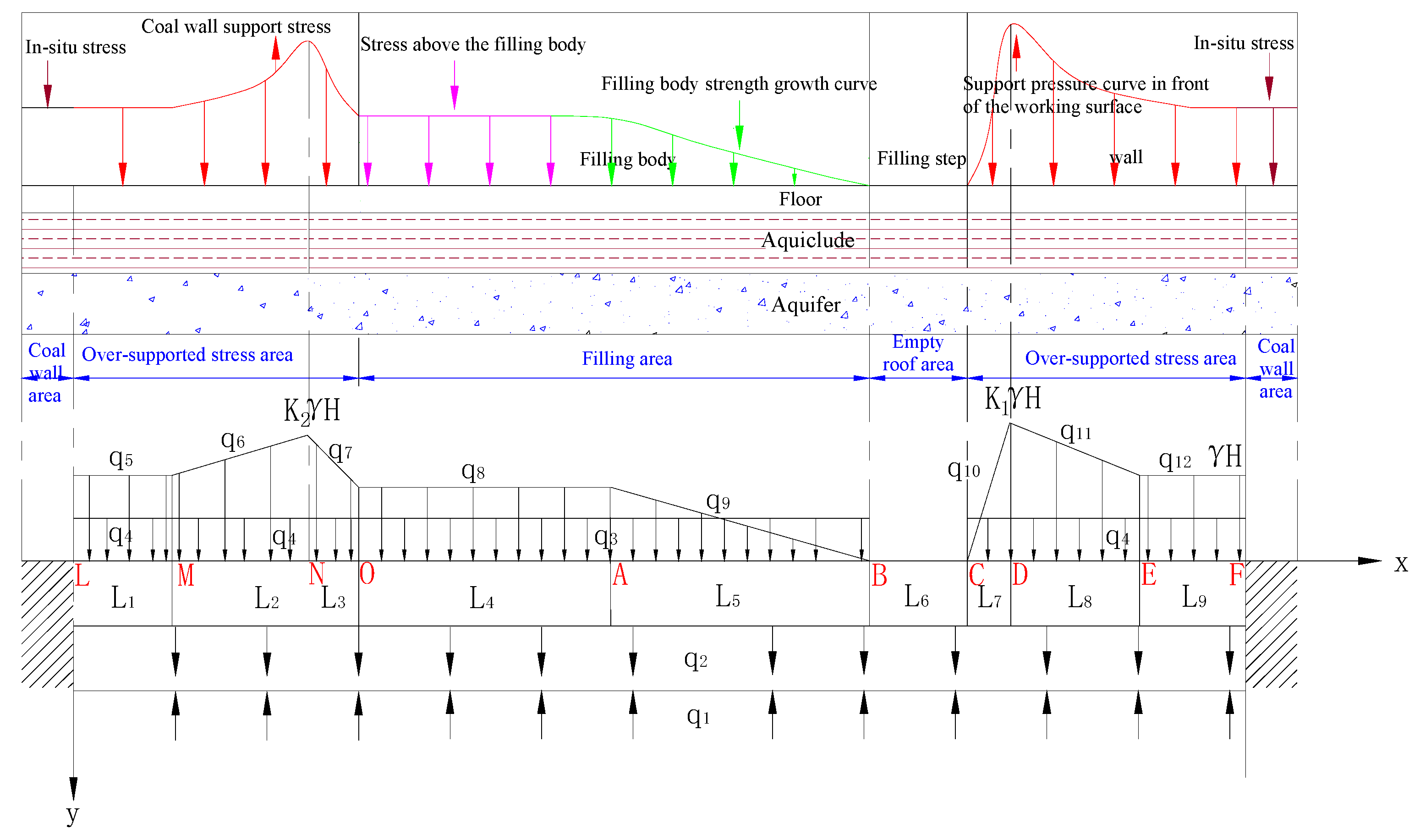
In this part, the elastic foundation beam theory is applied to calculate the bending deformation of the floor. Due to the length of the floor along the strike direction of the filling working face being much greater than the span in the inclined direction, it is approximately considered that the deformation of the floor is close and continuous. The floor and waterproof layer can be simplified as a mechanical analysis model of the elastic foundation beam. According to the actual situation, the corresponding pressure is applied to the floor, and the stress state of the floor under different filling steps and advance distance is simulated. The deflection and bending moment curve equation of the floor on the filling surface is established, and then, the relationship of the filling step, advance distance, the deformation, and failure of the floor is analyzed.
According to the coordinate system established in Figure 2, the deflection equation of the floor is analyzed step by step, in which is the superimposed pressure of confined water, is the deadweight pressure of a waterproof layer, is the self-weight pressure of the filling body, is the deadweight pressure of the coal body and, , represent the overlying pressure of the corresponding section floor, respectively.
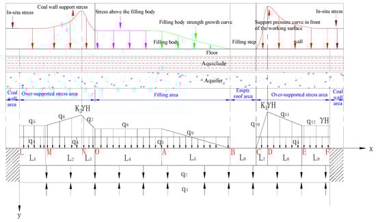
Figure 2.
Analysis model of overburden state and floor stress of paste-filling face.
- (1)
- For LM segment analysis:where is the superposition of the overlying pressure of the floor of the LM section, the self-weight pressure of the coal body, the self-weight pressure of the aquifer, and the pressure-bearing water pressure. That is:where —foundation coefficient of floor, N·m−3, and —pressure on LM section, N·m−2.
The characteristic coefficient α is taken . The deflection of the floor of the LM section is as follows:
When x tends to infinity, the deformation of the floor is a certain value. Due to the long floor at the left end, the floor is used as a semi-infinite beam. At this point, C1 = 0, D1 = 0, and the upper formula becomes:
- (2)
- For MN segment analysis:where is the superposition of the dead weight pressure of the coal body, the deadweight pressure of the waterproof layer, and the confined water pressure in the MN section. That is:
- (3)
- For NO section analysis, establish the floor deflection curve equation:where is the superposition of the self-weight pressure of the filling body of the NO section, the self-weight pressure of the water barrier, and the pressure-bearing water pressure, which is:
- (4)
- For OA section analysis, establish the floor deflection curve equation:
Among them, it is the superposition of the overburden pressure of the OA section, the self-weight pressure of the filling body, the self-weight pressure of the aquifer, and the pressure-bearing water pressure, which is:
- (5)
- For the AB section analysis, superimpose according to the superposition principle and establish the floor deflection curve equation:where is the superposition of the self-weight pressure of the filling body of the AB section, the self-weight pressure of the water barrier, and the pressure-bearing water pressure, which is:
- (6)
- Analyze the BC section and establish the floor deflection curve equation:where is the superposition of the self-weight pressure of the water barrier of the BC section and the pressure-bearing water pressure, which is:
- (7)
- Similar to the MN section, the CD section is analyzed, and the floor deflection can be obtained as:where is the superposition of the self-weight pressure of the coal body in the CD section, the self-weight load of the aquifer, and the pressure of pressurized water, which is:
- (8)
- Similar to the NO section, the DE section is analyzed, and the deflection of the floor can be obtained as:where is the superposition of the coal self-weight pressure of the DE section, the self-weight pressure of the aquifer, and the pressure-bearing water pressure, which is:
- (9)
- Similar to the LM section, the EF section is analyzed, and the deflection of the floor can be obtained as:
Since the rotation angle θ(x), bending moment M(x), shear force Q(x), and deflection w(x) of the arbitrary cross-section of the floor are related to:
From the continuity conditions between the various sections of the floor, one can obtain:
Maple is currently one of the most general mathematics and engineering calculation software, and it is widely used in the fields of science and engineering. Using Maple and bringing the relevant working face parameters into Equations (1)–(31), the corresponding parameters can be obtained: A1, B1, A2, B2, C2, D2, A3, B3, C3, D3, A4, B4, C4, D4, A5, B5, C5, D5, A6, B6, C6, D6, A7, B7, C7, D7, A8, B8, C8, D8, C9, and D9.
According to the actual situation of the mine, taking the filling step of 4 m and the working face advancing to 48 m as an example, the stress concentration factor at the coal wall of the open cut (K2) is taken as 1.8, and the stress concentration factor in front of the working face (K1) is taken as 2.1 based on empirical experiences. The foundation coefficient of the coal seam floor waterproof layer is set as 0.7 × 10⁸ N/m3. The elastic modulus of the coal seam floor is based on a field test. The relevant parameters are as follows: E 3.5 GPa, I = bh3/12, b = 1, h = 4, L1 = 20 m, L2 = 32 m, L3 = 8 m, L4 = 34 m, L5 = 10 m, L6 = 4 m, L7 = 8 m, L8 = 32 m, L9 = 20 m, q1 = −6.7 MPa, q2 = 1.25 MPa, q3 = 0.02 MPa, q4 = 0.03 MPa, q5 = 14 MPa, q6 = 0.125x + 19 MPa, q7 = −0.75x + 12 MPa, q8 = 12 MPa, q9 = −1.2x + 52.8 MPa, q10 = 0.2625x − 126 MPa, q11 = −7/32x +1064/32 MPa. Substituting Formulas (1)–(11), the floor deflection curve and bending moment curve under this condition can be obtained.
3.1. Analysis of Deformation and Failure of the Filling Floor under Different Filling Steps
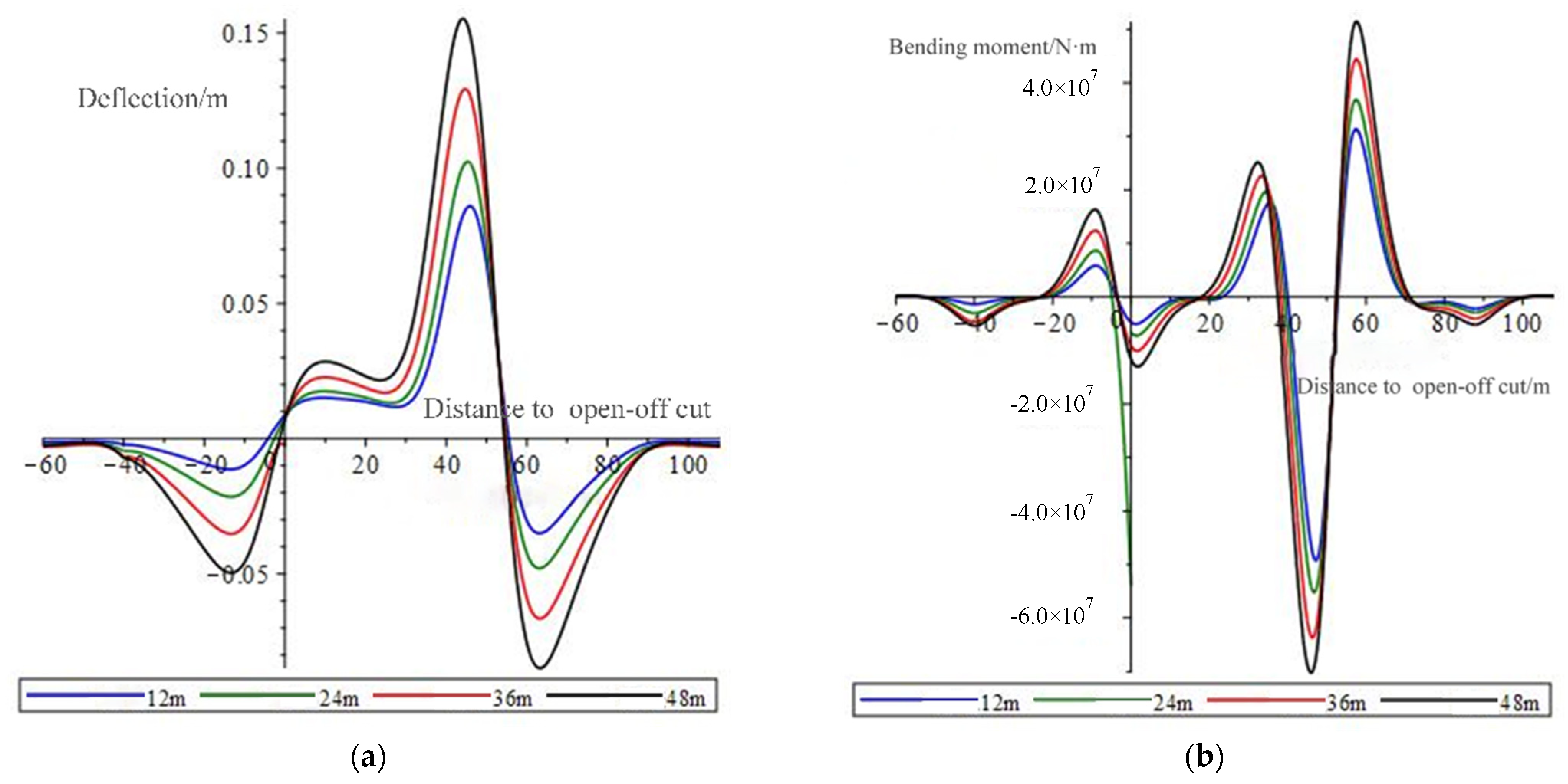
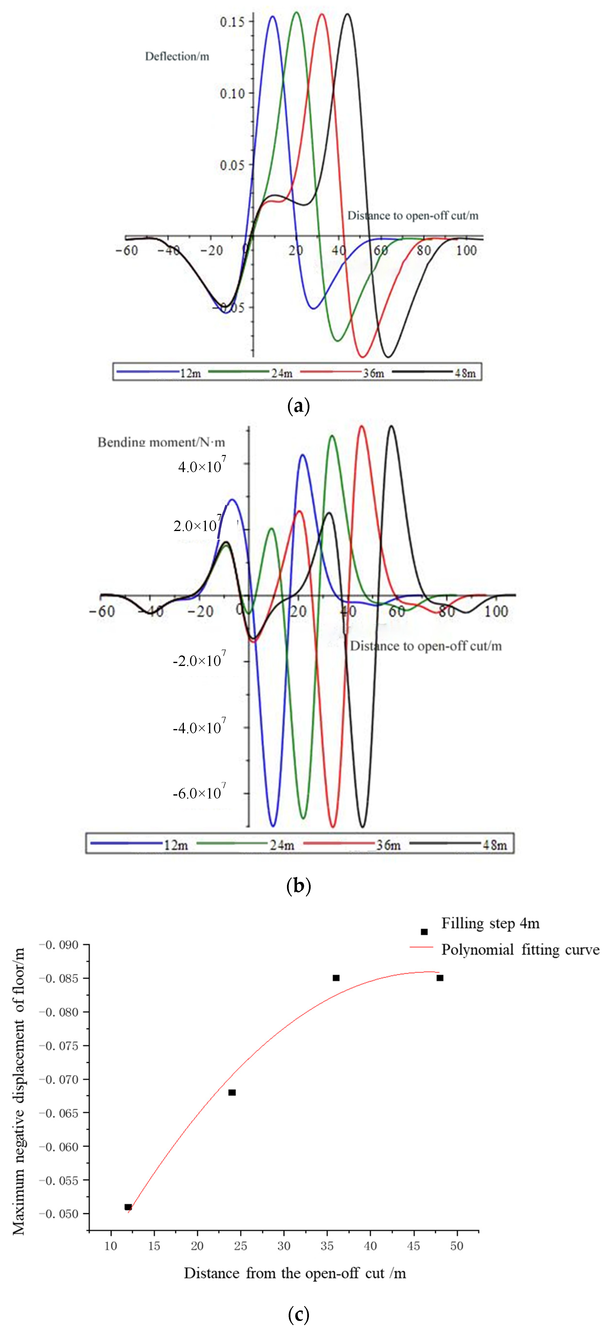
To compare the effect of the filling step on the damage of the floor, the filling steps of the working face are set as 1 m, 2 m, 3 m, and 4 m. The pressure gradually increases, and the supporting pressure coefficients are set as 1.8, 1.9, 2.0, and 2.1. When the working face is advanced to 48 m, the deflection curve of the floor is shown in Figure 3a, and the bending moment curve of the floor is shown in Figure 3b.
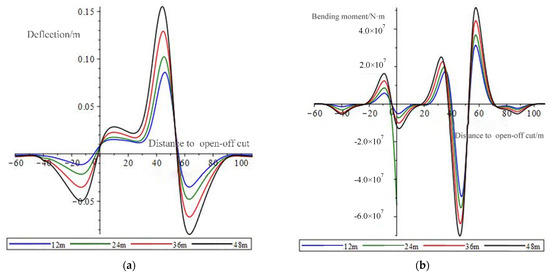
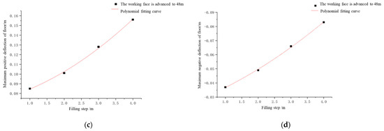
Figure 3.
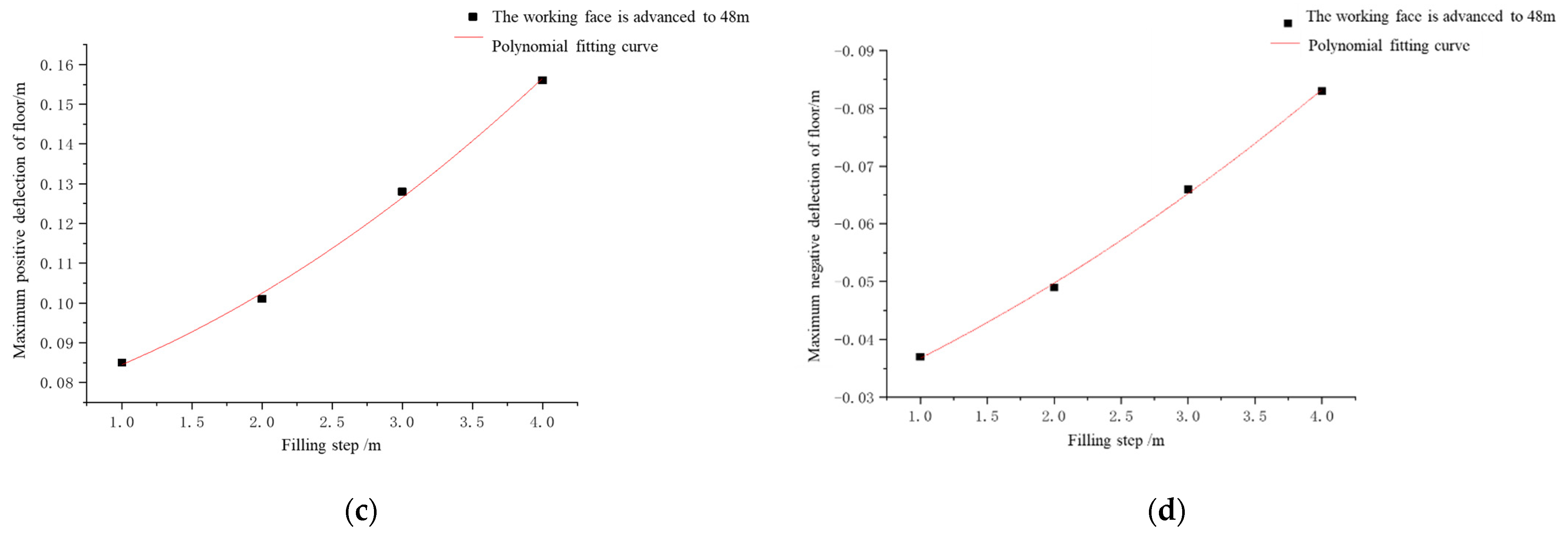
(a) Floor deflection under different filling steps; (b) Floor bending moment under different filling steps; (c) The relationship between the filling step and the maximum positive deflection of the floor; (d) The relationship between the filling step and the maximum negative deflection of the floor.
In Figure 3a, it can be seen that the impact of the change of the filling step on the floor is mainly reflected in the opening of the cut and the downward displacement of the floor at the coal wall. This can be explained by the bending moment diagram in Figure 3b. The bending moments at the open cut and the working face are positive, indicating that the two positions are subjected to compressive stress and therefore will produce downward displacement. In the empty roof area, the bending moment of the floor is negative, indicating that the floor in the empty top area is under tensile stress. With the increase in the filling step, the corresponding bending moments at each position of the floor continue to increase.
By fitting the maximum displacement of the floor, it is obtained that the maximum positive displacement of the floor and the filling step show a “concave” quadratic function relationship shown in Figure 3c. The function relationship is . The maximum negative displacement of the floor and filling step presents a “concave” quadratic function relationship shown in Figure 3d. The function relationship is . From the aforementioned two formulas, it can be concluded that with the increase in the filling step, the displacement and deformation of the floor will continue to increase. Therefore, the size of the filling step is closely related to the damage degree of the floor.
3.2. Analysis of Deformation and Failure of the Filling Floor under Different Advancing Distances
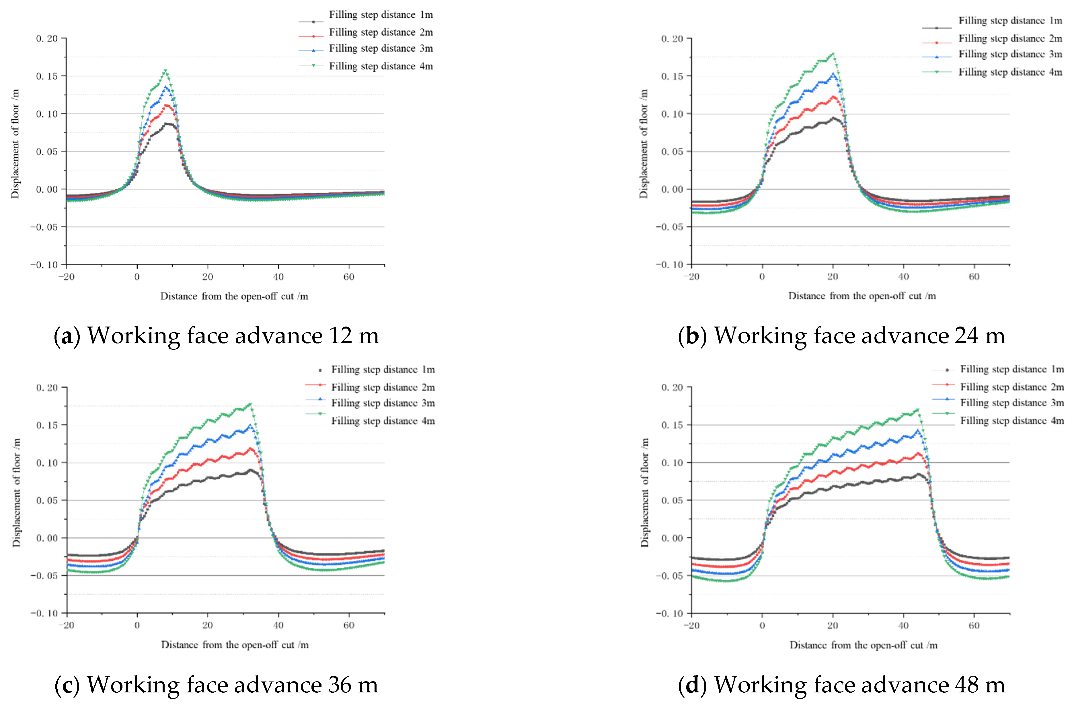
To compare the influence of advancing distance on the damage of the floor, the advancing distances of the working face are taken as 12 m, 24 m, 36 m, and 48 m. When the filling step of the working face is 4 m, the deflection curve of the floor is shown in Figure 4a. The bending moment curve is shown in Figure 4b.
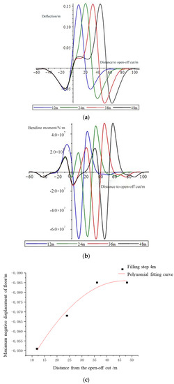
Figure 4.
(a) Floor deflection at different advancing distances of paste-filling working face; (b) Bending moment of the floor under different advancing distances of paste-filling working face; (c) The relationship between the different advancing distances of the paste-filling working face and the maximum negative deflection of the floor.
The floor flection during the advancement of the filling surface is shown in Figure 4a, which can be regarded as the dynamic change process. Under the action of high stress on the coal walls, floor heave occurs in the goaf. With the advancement of the working face, the deformation and failure of the floor show the following tendency. First of all, the maximum heave of the goaf floor remains unchanged. The main reason is that the system of “filling body–empty roof–coal wall” is formed during the advancement of the working face. Secondly, as the working face advances, the floor heave of the filled area gradually decreases. The main reason is that the filling body plays a role in transmitting the pressure of the overburden. Under the action of the overburdened pressure, the deformation of the floor is suppressed and gradually compressed. Hence, the floor volume is reduced. Figure 4b can be seen as the dynamic change process of the floor bending moment during the advancing process of the filling surface. The side bending moment of the coal wall is positive, indicating that the coal body is compressed, and as the working face advances, the bending moment in the filled area is also positive. Therefore, the coal body in this area is also under pressure, which is the main reason for the gradual decrease in the floor heave in the filled area. As the advancing distance of the working face increases, the bending moment in front of the coal wall of the working face gradually increases and then stabilizes.
It is obtained that the maximum negative displacement of the floor and the advancing distance of the filling surface show a “convex” quadratic function relationship shown in Figure 4c. The function relationship is . There is a downward displacement of the floor before the work. The amount gradually increases and then stabilizes, indicating that the increase in the advancing distance will increase the destruction depth of the floor, but when it is advanced to a certain distance, the damage depth of the floor will no longer continue to increase and maintain a stable value.
4. Numerical Simulation
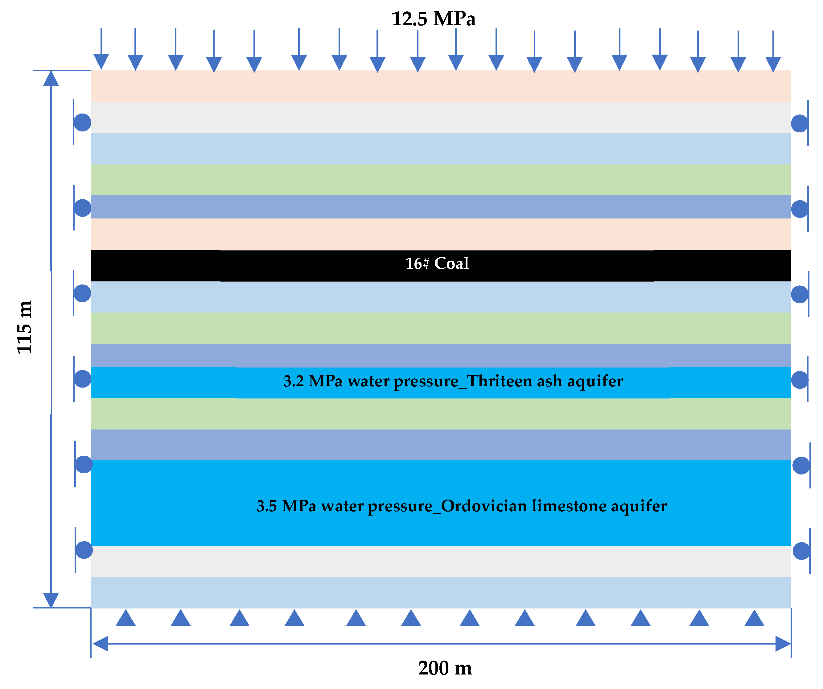
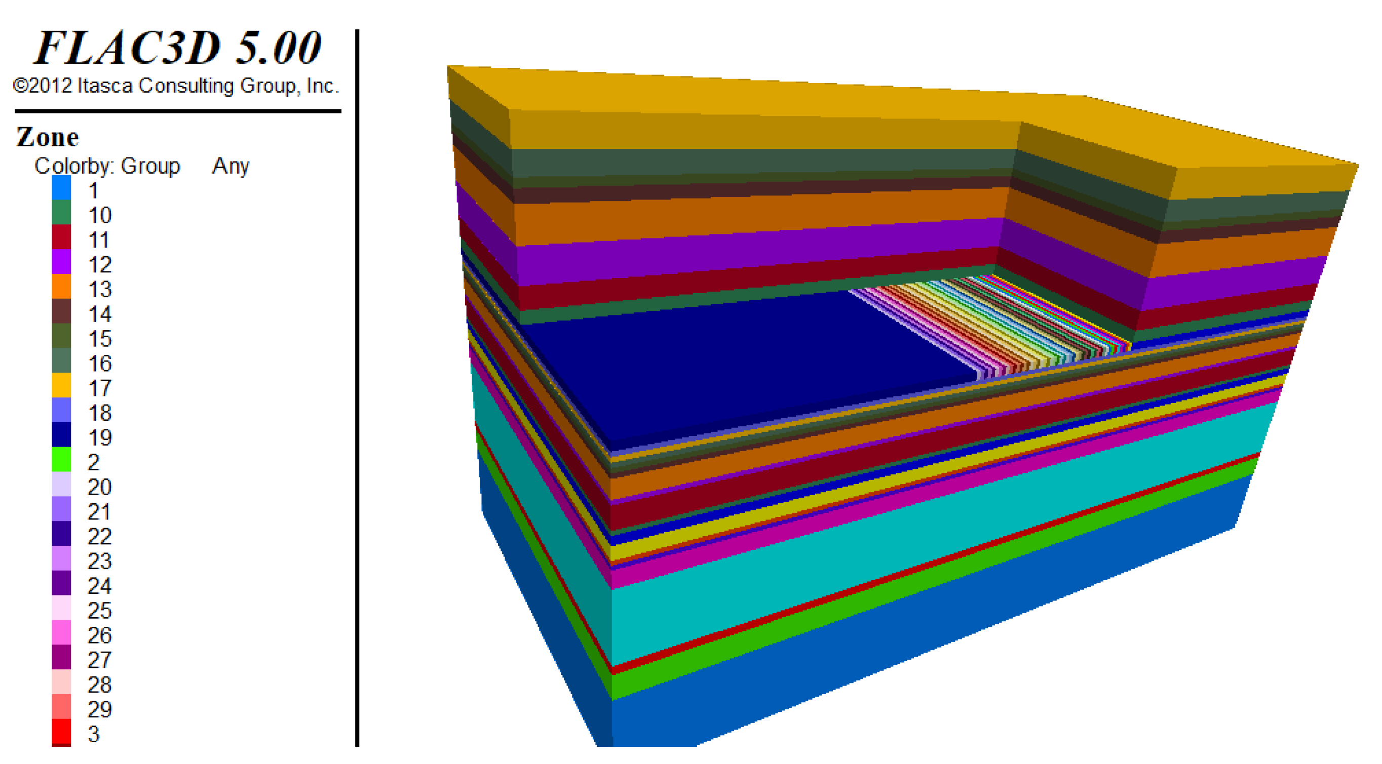
To verify the accuracy of the theoretical analysis in this paper, FLAC3D5.0 is used to construct a numerical simulation for calculation. FLAC3D 5.0 is a three-dimensional numerical simulation software developed based on the finite difference method, which has been widely used in the field of rock and soil mechanics. In this paper, combined with the actual situation of the 11,607 working face, a simplified model is established, as shown in Figure 5. Based on the field measurement, laboratory test, and GSI method, the rock mass properties are given in Table 2 and a numerical model is shown in Figure 6. Horizontal displacement constraints are imposed on the left and right boundaries of the model, and the bottom boundary of the model is fixed in the vertical direction. The top rock layer of the model is about 500 m away from the ground. Therefore, a vertical downward 12.5 MPa uniform pressure is applied to the top to simulate the overburden pressure. To consider the impact of confined water, the software built-in fluid–solid coupling model is used to give a confined water pressure of 3.2 MPa in the 13th ash aquifer and 3.5 MPa in the Ordovician aquifer according to the test results. To eliminate the influence of the boundary of the model, 76 m boundary coal pillars are left on both sides of the working face along the advancing direction, and the size of the model is 200 m × 100 m × 115 m. The rectangular grid elements are introduced in analysis models, and the accuracy and efficiency of such elements have been verified by many studies. The time step is reached when the maximal unbalanced force is lower than 1 × 10⁻⁵. We set key rock mass layers (e.g., coal layer) with the mesh of 1 m, and far away that, we used the mesh of 2 m and 4 m. The rock mass parameters are set in Table 2. The Mohr–Coulomb strength criterion is used for rock mass. Although the Mohr–Coulomb criterion is not very appropriate for rock mass, it is a widely used model in which the parameters are easy to obtain and use considering the previous studies. Thus, in this study, we used the MC criterion to investigate the basic laws.
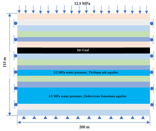
Figure 5.
Geometric model diagram.
Table 2.
Mechanical parameters of rock mass of the model.

Figure 6.
Numerical simulation model.
The setting of the strength parameters of the filling body is shown in Table 2. The filling rate is taken as 98%, and the mined-out area is filled continuously as the working face advances. The floor stress, displacement, and plastic zone under filling steps of 1, 2, 3, and 4 m and advancing distances of 12, 24, 36, and 48 m are simulated correspondingly.
4.1. Floor Stress Influenced by Filling Step and Advancing Distance
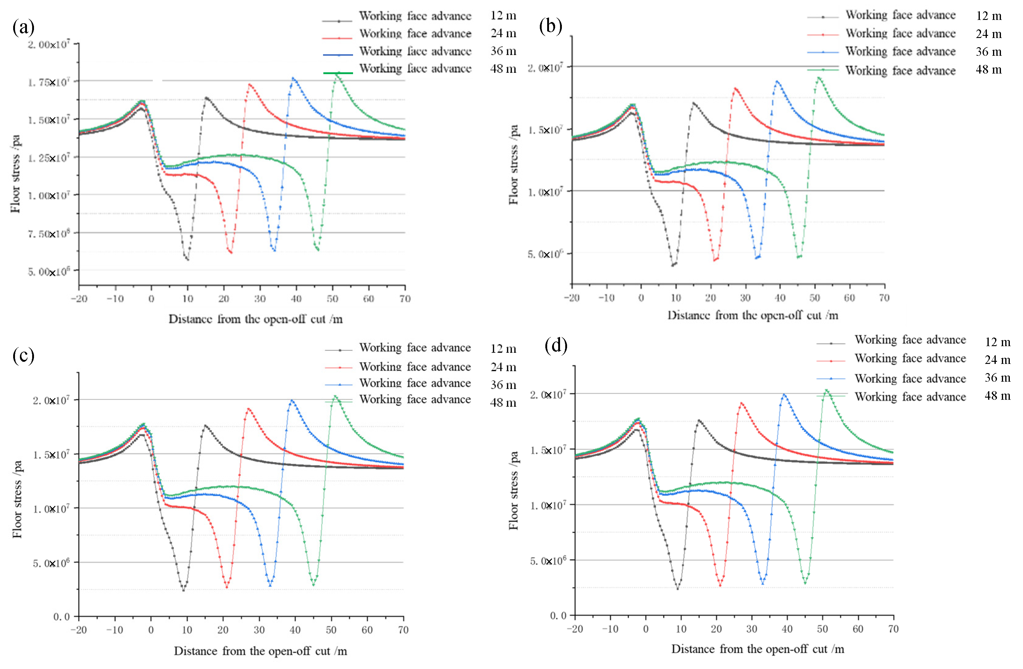
The filling steps of the paste-filling working face are 1, 2, 3, and 4 m, and the advancing distances are 12, 24, 36, and 48 m. Figure 7 shows the vertical stress of the floor under different filling steps and advancing distances.
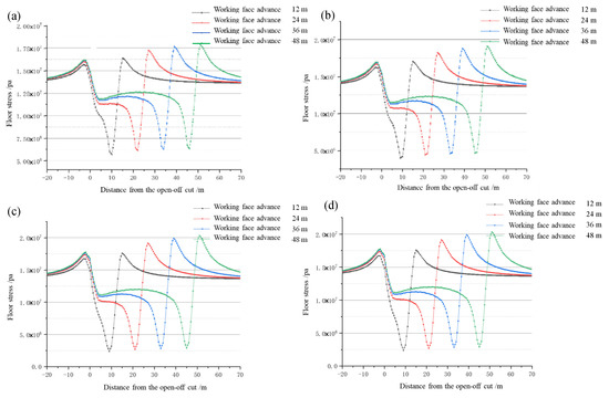
Figure 7.
Abutment pressure in front of coal wall of the paste-filling face under different filling steps. (a) Filling step distance 1 m, (b) Filling step distance 2 m, (c) Filling step distance 3 m, (d) Filling step distance 4 m.
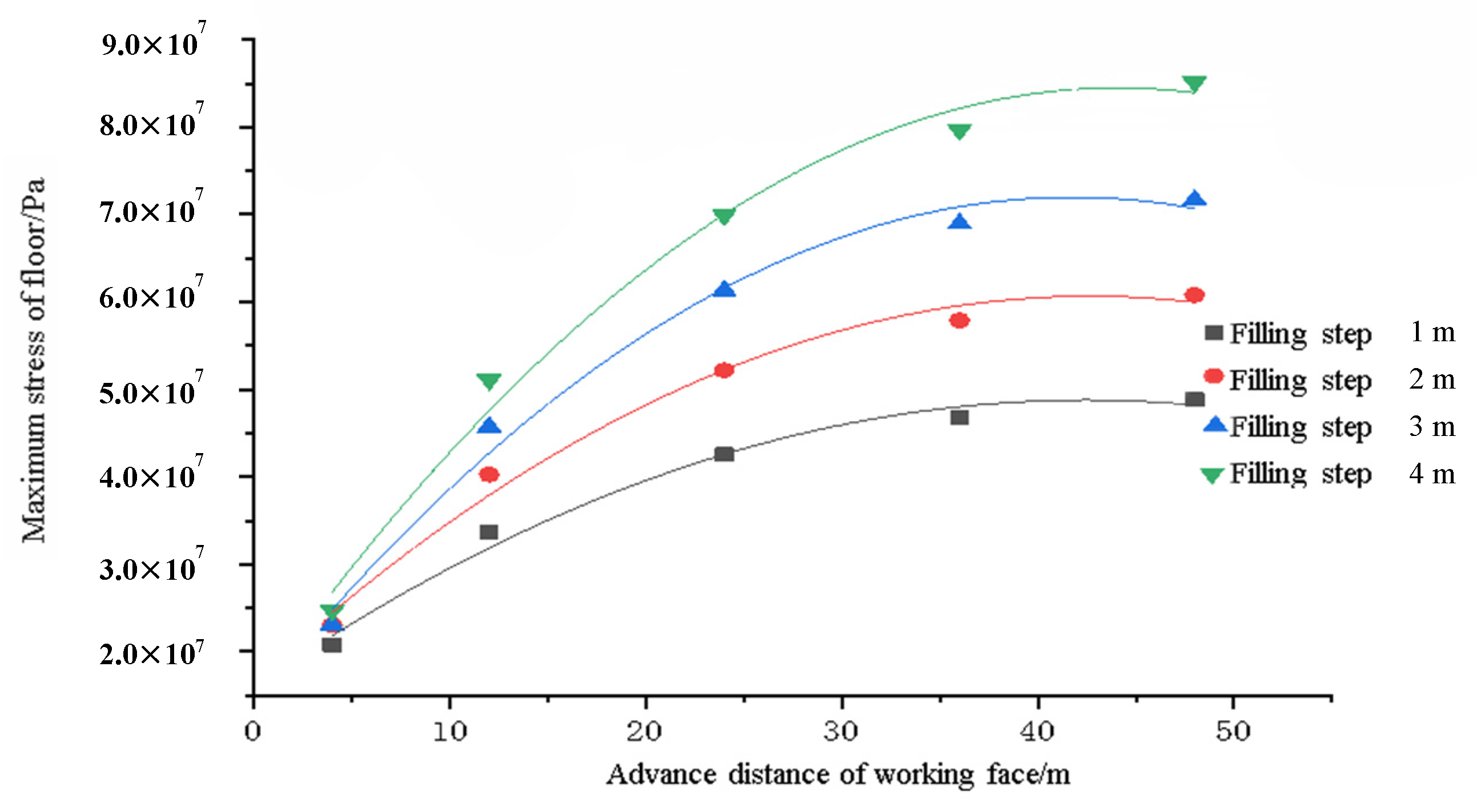
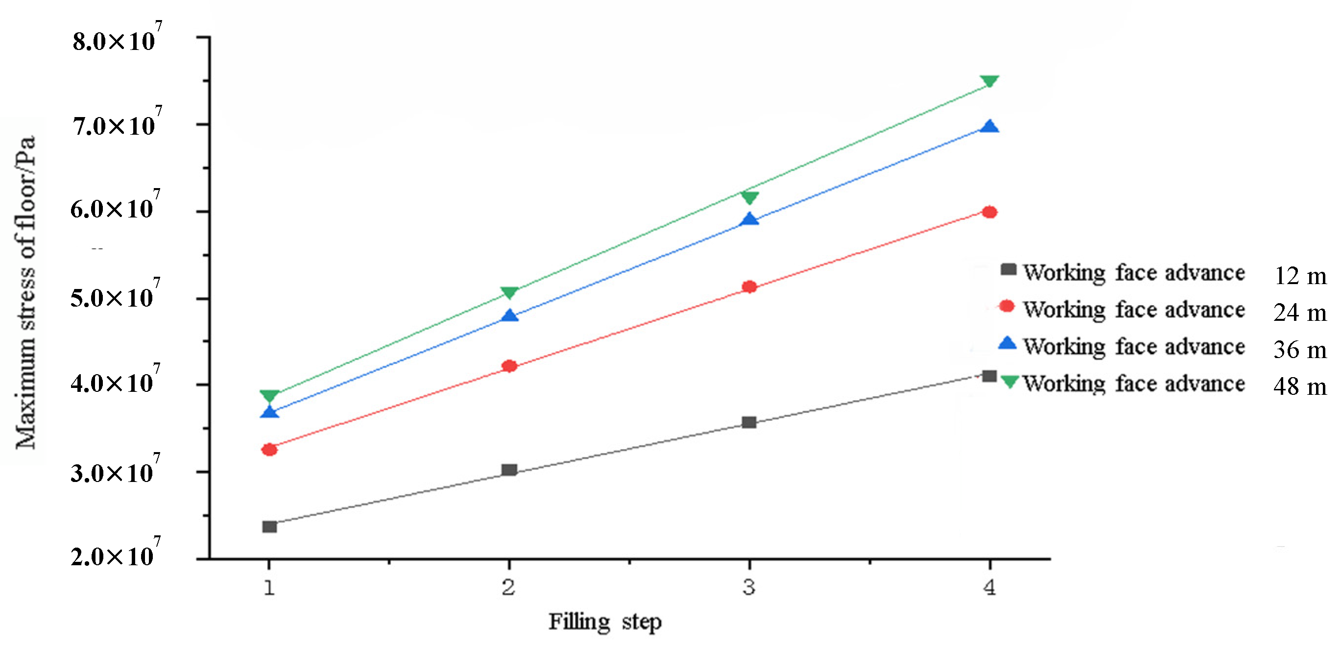
The stress of the floor of the paste-filling working face is shown in Figure 7. It can be seen that the stress on the floor above the work surface presents a general law that first increases suddenly and then gradually decreases to the original rock stress. The stress concentration of the floor in front of the coal body is often caused by the excavation of the coal mass, which is also the location where the floor failure begins to occur. The peak stress of the floor shows a regular change with the change of the filling step and the advancing distance. Figure 8 and Figure 9 are obtained by fitting the maximum stress of the floor under different advancing distances and different filling steps.
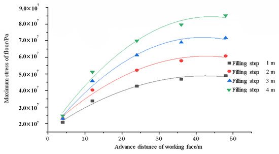
Figure 8.
The relationship between the maximum stress of paste-filling face floor and the advancing distance of working face under different filling steps.
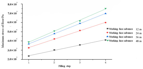
Figure 9.
The relationship between the maximum stress of the paste-filling working face floor and the filling step under different advancing distances.
As shown in Figure 8, when the filling step is fixed, the working surface will advance from 12 to 48 m as the paste is filled. The maximum stress of the floor keeps increasing, and the increasing amplitude keeps decreasing, showing a quadratic function relationship. When it is advanced to 36 m, it tends to a constant value. It shows that at 36 m, the “filling body–empty roof area–coal wall” forms a stable support system. As the advancing distance continues to increase, the maximum stress of the floor will not increase, and the floor will be damaged.
When the advancing distance is constant, the maximum stress of the floor changes significantly with the change of the filling step. As shown in Figure 9, the filling step and the maximum stress of the floor show a linear relationship. As the step length increases, the maximum stress of the floor will continue to increase, and the increase will gradually increase, indicating that the change of the filling step length has a greater impact on the damage degree of the floor. The main reason is that the increase in the filling step will increase the range of the empty roof area of each round of filling. For the “filling body–empty roof area–coal wall” support system, it is necessary to achieve stability. The concentrated stress on the front will inevitably increase and be transmitted to the floor, resulting in deformation and damage of the floor. Therefore, the size of the filling step will be more important for the destruction of the floor during the continuous advancement of the working face.
4.2. Floor Displacement Influenced by Filling Step and Advancing Distance
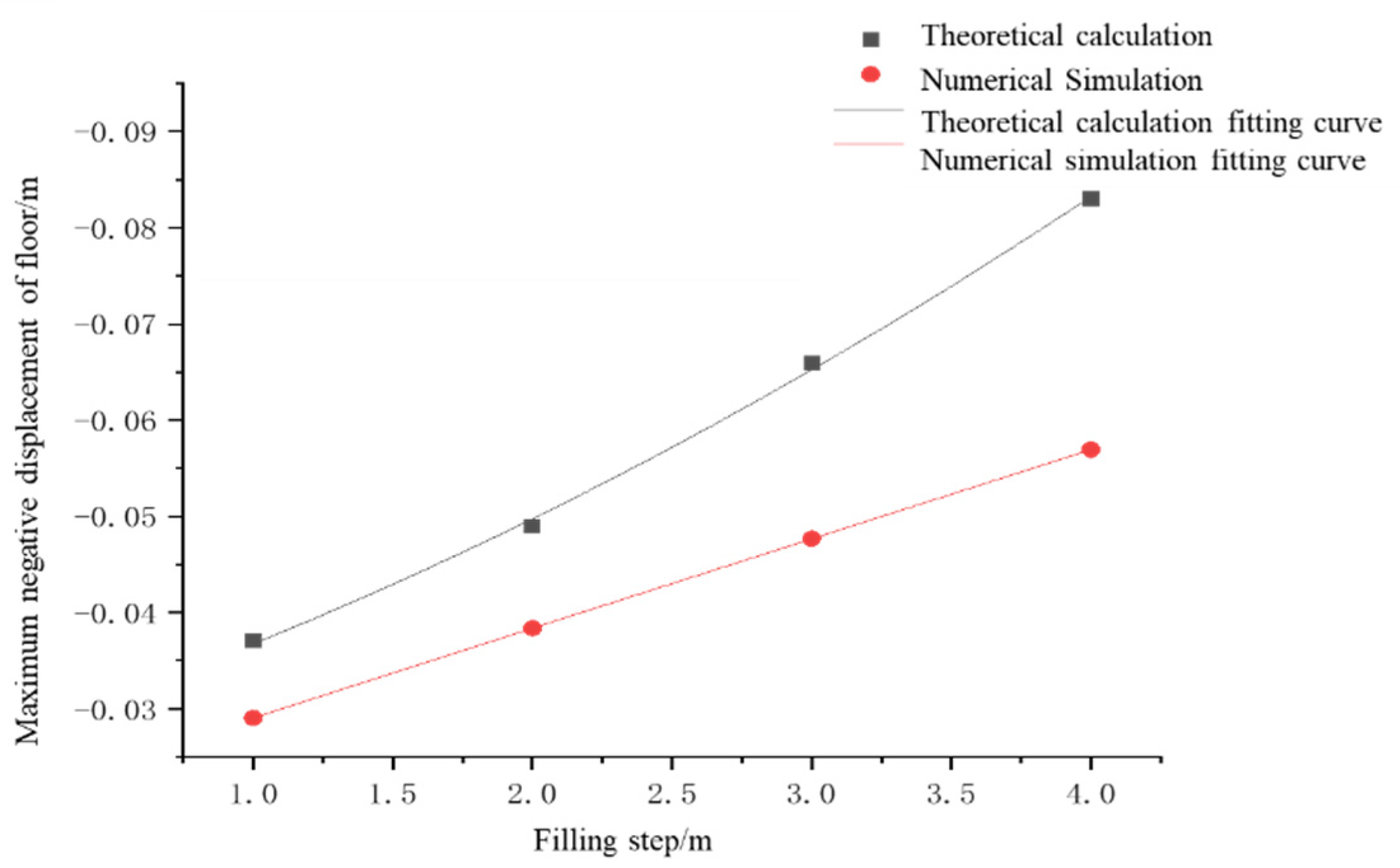
The filling steps of the paste filling working face are 1, 2, 3, and 4 m, and the advancing distances are 12, 24, 36, and 48 m. Under different filling steps, the displacement diagram is shown in Figure 10. Under different advancing distances of the working face, the relationship between the filling step and the maximum displacement of the floor is shown in Figure 11.
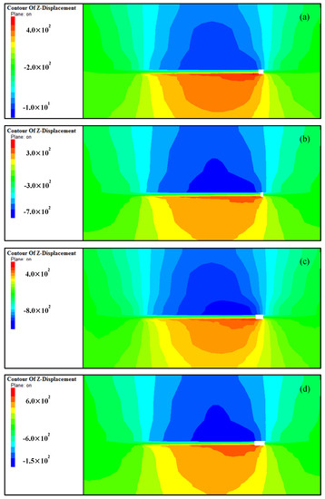
Figure 10.
Floor displacement under different filling steps of paste-filling working face. (a) Filling step distance 1 m, (b) Filling step distance 2 m, (c) Filling step distance 3 m, (d) Filling step distance 4 m.
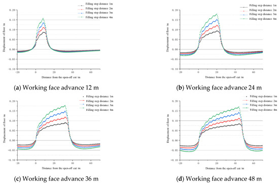
Figure 11.
Floor displacement under different filling steps of paste-filling working face.
It can be seen from Figure 10 and Figure 11 that the maximum positive displacement of the floor of the working face filled with paste often occurs in front of the coal wall of the working face. However, the maximum negative displacement occurs behind the coal wall of the working face, which is also the position where the floor is most likely to be damaged. The main reason is that the “filling body–empty roof area (filling step)–coal wall” support system has been formed. Under the action of concentrated stress, the floor is often prone to damage at this position. In the empty roof area, due to the release of the floor stress, the floor heave is likely to occur.
By fitting numerical simulation results in Figure 12, Figure 13 and Figure 14 (filling step, maximum displacement of the floor, and advancing distances), it is found that the fitting curves are close to the previous theoretical calculation. It is similar to the maximum deflection curve of the floor. When verifying the previous theoretical calculations, it also shows that the influence of the filling step on the deformation and failure of the floor gradually increases with the increase in the filling step. The influence of the advancing distance on the deformation and failure of the floor increases gradually.
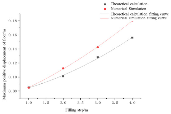
Figure 12.
The relationship between different filling steps and the maximum positive displacement of the floor.
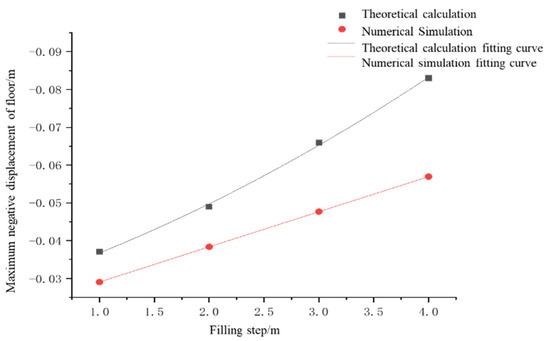
Figure 13.
The relationship curve between different filling steps and the maximum negative displacement of the floor.
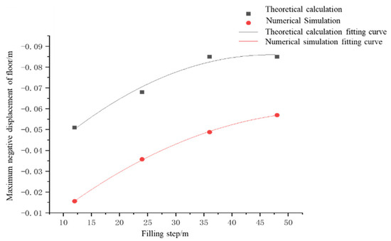
Figure 14.
The relationship between different advancing distances and the maximum negative displacement of the floor.
Therefore, there is a “concave” quadratic function relationship between the maximum displacement of the floor and the filling step, and a “convex” quadratic function relationship between the maximum displacement and the advancing distance. The deformation and failure of the floor in the initial stage of the working face will be affected by the filling step and the advancing distance at the same time. When it is advanced to a certain distance, the deformation and failure of the floor will be mainly controlled by the filling step.
4.3. Destruction Depth Influenced by Filling Step and the Advancing Distance
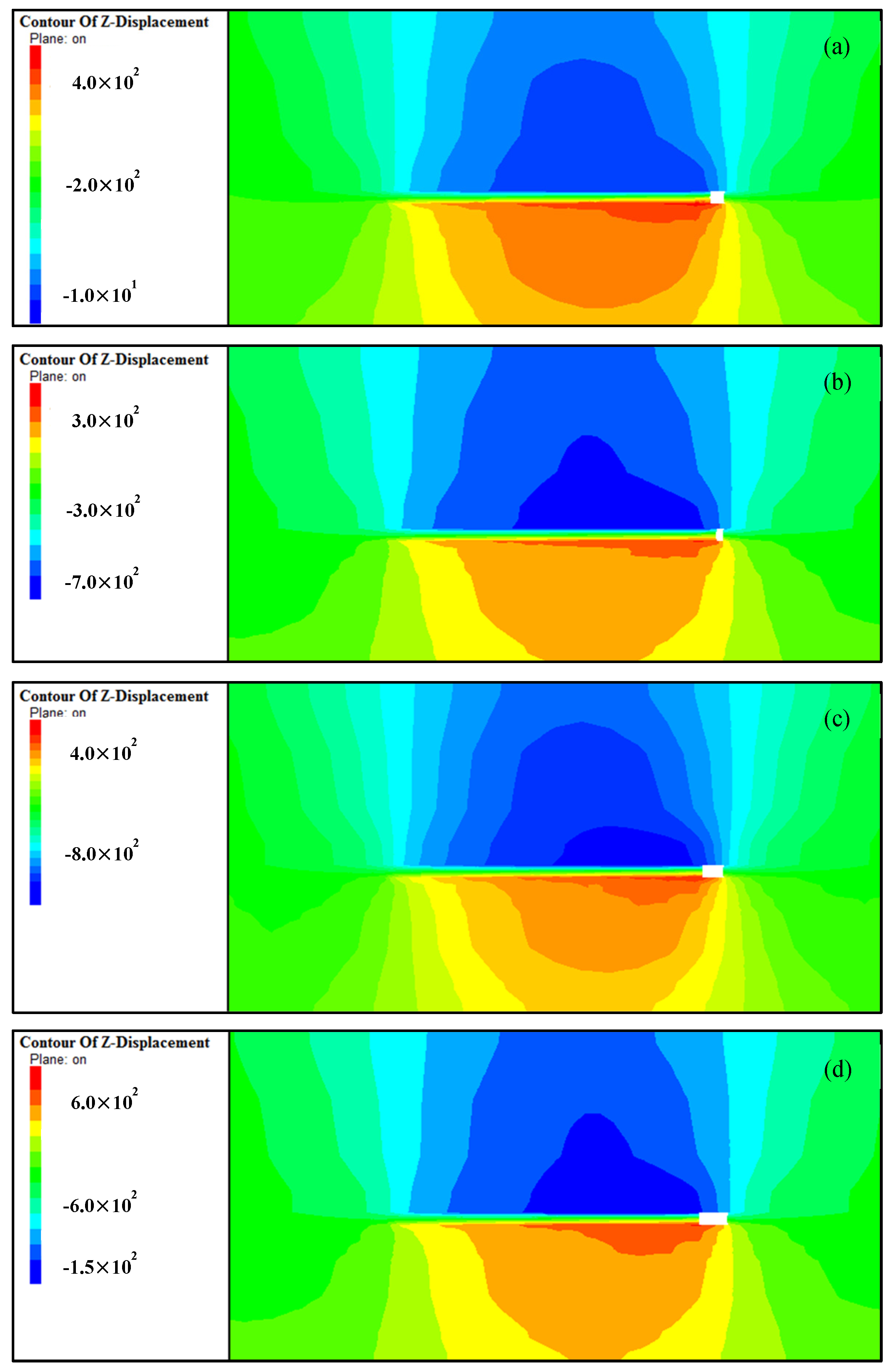
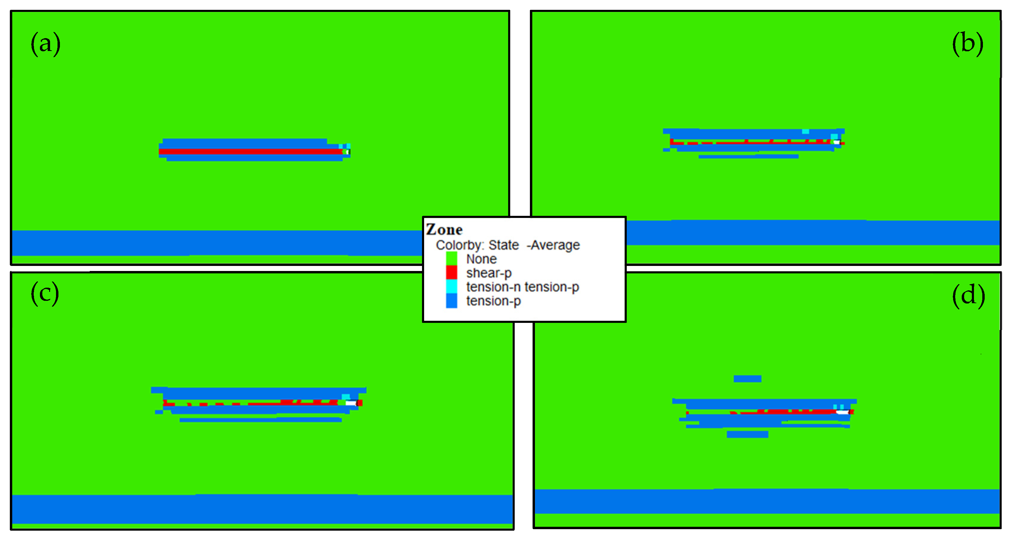
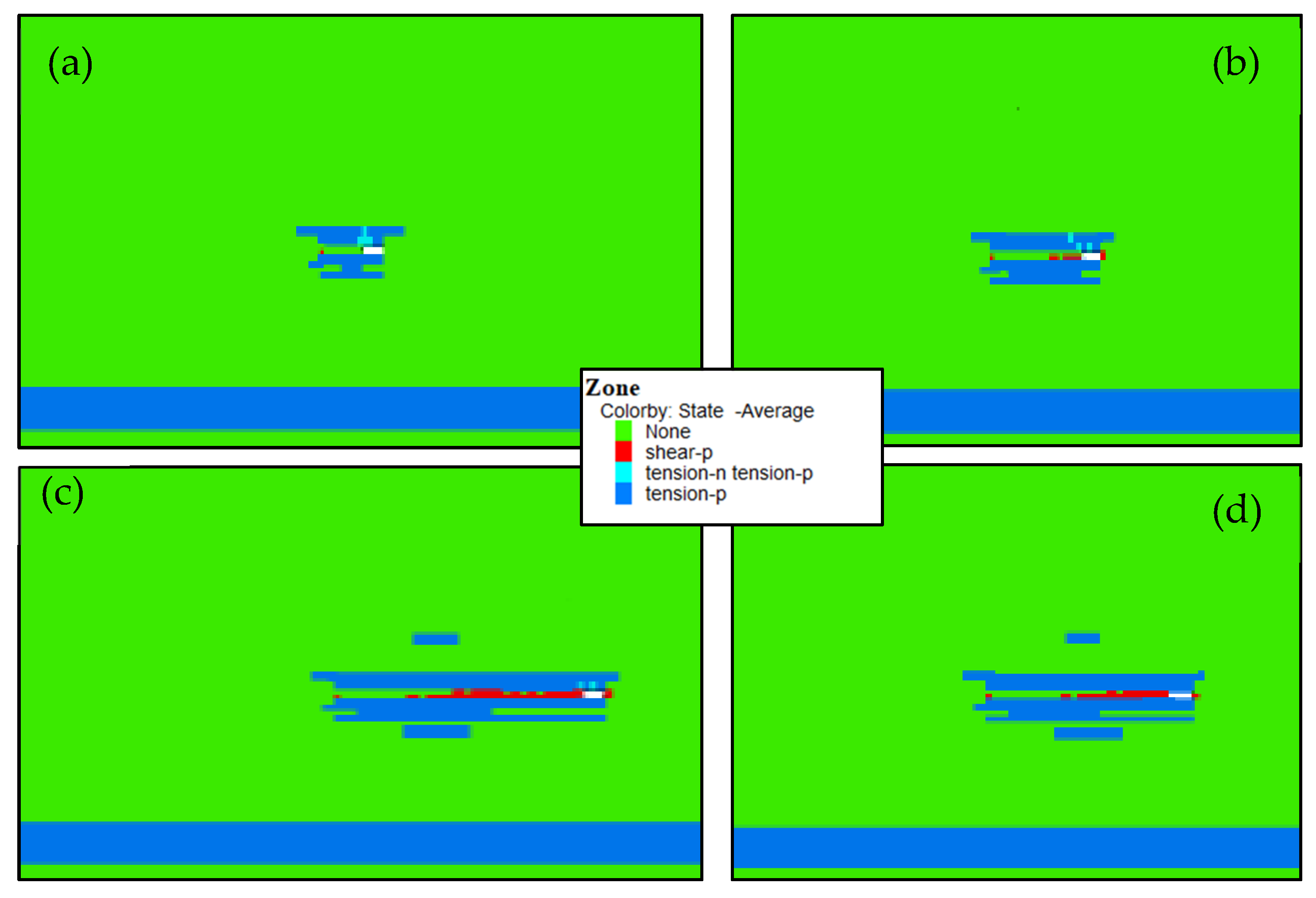
The filling step distances of the paste-filling working face are 1, 2, 3, and 4 m, and the advancing distances are 12, 24, 36, and 48 m. When the working face is advanced to 48 m, the plastic zone of the floor under different filling steps is shown in Figure 15. When the filling step is 4 m, the plastic zone of the floor under different advancing distances is shown in Figure 16.

Figure 15.
Plastic zone in the paste-filling working face under different filling steps of (a) 1 m, (b) 2 m, (c) 3 m, and (d) 4 m.

Figure 16.
Plastic zone in paste-filling face under different advancing distances: (a) 12 m, (b) 24 m, (c) 36 m. and (d) 48 m.
The damage to the floor often begins to develop from the front end of the coal wall. Since the paste-filling body has the function of supporting the roof and transferring the pressure, the supporting pressure is greatly reduced, and the damage degree of the floor is extremely controlled. The damage to the floor does not cause the water barrier layer failure, which meets the requirements for safe mining on confined water. It can be seen from Figure 15 and Figure 16 that the floor damage depth gradually increases from 2 to 7 m, the degree of penetration gradually increases, and the confined aquifer plastic failure has not progressed upward. After setting the filling step of the working face to 4 m, and changing the advancing distance to 12 m, 24 m, 36 m, and 48 m, the floor failure depth is maintained at 4 m. Therefore, under certain conditions of filling parameters, the increase in the filling step will cause the vertical damage depth of the floor, and the increase in the advancing distance mainly causes the increase in the horizontal damage range of the floor.
5. Conclusions
- (1)
- Combined with the geological conditions of the 11,607 areas of the working face of Daizhuang Mine, a differential equation for the deflection curve of the floor is established. The maximum deflection of the floor and the advancing distance present a “convex” quadratic function relationship, and as the advancing distance increases, the increase in the displacement of the floor will continue to decrease.
- (2)
- It is verified by numerical simulation that the filling step and the maximum stress of the floor show a linear relationship. During the continuous advancement of the working face, the setting of the filling step has a significant influence on the damage degree of the floor.
- (3)
- With the increase in the advancing distance, the maximum stress of the floor gradually stabilizes. The maximum deflection of the floor and the advancing distance also show a “convex” quadratic function relationship. Therefore, when the working face advances more than a certain distance (36 m in this mine), the longitudinal damage of the floor will not increase with the increase in the advance distance.
Author Contributions
Conceptualization by Q.C.; methodology, X.Y.; investigation, Q.C., J.Q.; writing—original draft preparation, Q.C., J.Q., M.L. and Y.W.; writing—review and editing H.Z., Y.S. and Y.X.; supervision, Q.C.; funding acquisition, Q.C. and H.Z. All authors have read and agreed to the published version of the manuscript.
Funding
This research was supported by the projects of “the Fundamental Research Funds for the Central Universities (2020ZDPY0221, 2021QN1003)”, “National Natural Science Foundation of China (52174130, 52104106, 52174089)”, and Basic Research Program of Xuzhou (KC21017).
Institutional Review Board Statement
Not applicable.
Informed Consent Statement
Not applicable.
Data Availability Statement
The data presented in this study are available on request from the corresponding author. The data are not publicly available due to privacy.
Acknowledgments
The authors are grateful to Gaohe coal mine.
Conflicts of Interest
The authors declare no conflict of interest.
References
- Zhang, Y.; Yang, L. A novel dynamic predictive method of water inrush from coal floor based on gated recurrent unit model. Nat. Hazards 2021, 105, 2027–2043. [Google Scholar] [CrossRef]
- Hu, Y.; Li, W.; Wang, Q.; Liu, S.; Wang, Z. Evaluation of water inrush risk from coal seam floors with an AHP-EWM algorithm and GIS. Environ. Earth Sci. 2019, 78, 290. [Google Scholar] [CrossRef]
- Gui, H.; Song, X.; Lin, M. Water-inrush mechanism research mining above karst confined aquifer and applications in North China coalmines. Arab. J. Geosci. 2017, 10, 180. [Google Scholar] [CrossRef]
- Sun, Y.; Li, G.; Zhang, J.; Sun, J.; Huang, J.; Taherdangkoo, R. New Insights of Grouting in Coal Mass: From Small-Scale Experiments to Microstructures. Sustainability 2021, 13, 9315. [Google Scholar] [CrossRef]
- Zhou, D.; Wu, K.; Bai, Z.; Hu, Z.; Li, L.; Xu, Y.; Diao, X. Formation and development mechanism of ground crack caused by coal mining: Effects of overlying key strata. Bull. Eng. Geol. Environ. 2019, 78, 1025–1044. [Google Scholar] [CrossRef]
- Jiang, N.; Wang, C.; Pan, H.; Yin, D.; Ma, J. Modeling study on the influence of the strip filling mining sequence on mining-induced failure. Energy Sci. Eng. 2020, 8, 2239–2255. [Google Scholar] [CrossRef]
- Sun, Y.; Li, G.; Zhang, J.; Huang, J. Rockburst intensity evaluation by a novel systematic and evolved approach: Machine learning booster and application. Bull. Eng. Geol. Environ. 2021, 80, 8385–8395. [Google Scholar] [CrossRef]
- He, J.; Li, W.; Qiao, W. P-H-q evaluation system for risk assessment of water inrush in underground mining in North China coal field, based on rock-breaking theory and water-pressure transmission theory. Geomat. Nat. Hazards Risk 2018, 9, 524–543. [Google Scholar] [CrossRef] [Green Version]
- Liu, W.; Mu, D.; Xie, X.; Yang, L.; Wang, D. Sensitivity Analysis of the Main Factors Controlling Floor Failure Depth and a Risk Evaluation of Floor Water Inrush for an Inclined Coal Seam. Mine Water Environ. 2018, 37, 636–648. [Google Scholar] [CrossRef]
- Liu, S.; Liu, W.; Shen, J. Stress evolution law and failure characteristics of mining floor rock mass above confined water. Ksce J. Civ. Eng. 2017, 21, 2665–2672. [Google Scholar] [CrossRef]
- Sun, W.; Zhang, S.; Guo, W.; Liu, W. Physical Simulation of High-Pressure Water Inrush through the Floor of a Deep Mine. Mine Water Environ. 2017, 36, 542–549. [Google Scholar] [CrossRef]
- Sun, J.; Hu, Y.; Zhao, G. Relationship between water inrush from coal seam floors and main roof weighting. Int. J. Min. Sci. Technol. 2017, 27, 873–881. [Google Scholar] [CrossRef]
- Lu, Y.; Wang, L. Numerical simulation of mining-induced fracture evolution and water flow in coal seam floor above a confined aquifer. Comput. Geotech. 2015, 67, 157–171. [Google Scholar] [CrossRef]
- Yin, S.; Zhang, J.; Liu, D. A study of mine water inrushes by measurements of in situ stress and rock failures. Nat. Hazards 2015, 79, 1961–1979. [Google Scholar] [CrossRef]
- Zhang, W.; Zhang, D.; Qi, D.; Hu, W.; He, Z.; Zhang, W. Floor failure depth of upper coal seam during close coal seams mining and its novel detection method. Energy Explor. Exploit. 2018, 36, 1265–1278. [Google Scholar] [CrossRef] [Green Version]
- Sun, Y.; Li, G.; Zhang, J. Developing hybrid machine learning models for estimating the unconfined compressive strength of jet grouting composite: A comparative study. Appl. Sci. 2020, 10, 1612. [Google Scholar] [CrossRef]
- Apaydin, A.; Korkmaz, N.; Ciftci, D. Water inflow into tunnels: Assessment of the Gerede water transmission tunnel (Turkey) with complex hydrogeology. Q. J. Eng. Geol. Hydrogeol. 2019, 52, 346–359. [Google Scholar] [CrossRef]
- Butscher, C.; Scheidler, S.; Farhadian, H.; Dresmann, H.; Huggenberger, P. Swelling potential of clay-sulfate rocks in tunneling in complex geological settings and impact of hydraulic measures assessed by 3D groundwater modeling. Eng. Geol. 2017, 221, 143–153. [Google Scholar] [CrossRef]
- Golian, M.; Teshnizi, E.S.; Nakhaei, M. Prediction of water inflow to mechanized tunnels during tunnel-boring-machine advance using numerical simulation. Hydrogeol. J. 2018, 26, 2827–2851. [Google Scholar] [CrossRef]
- Sedaghati, Z.; Mikaeil, R.; Bakhtavar, E.; Mohammadnejad, M. Fuzzy Analysis and Risk Management of Water Inrush by Numerical Simulation and FMEA under Uncertainty for Emamzade Hashem Tunnel. J. Anal. Numer. Methods Min. Eng. 2019, 9, 1–16. [Google Scholar]
- Dammyr, Ø.; Nilsen, B.; Gollegger, J. Feasibility of tunnel boring through weakness zones in deep Norwegian subsea tunnels. Tunn. Undergr. Space Technol. 2017, 69, 133–146. [Google Scholar] [CrossRef]
- Ma, K.; Sun, X.Y.; Tang, C.A.; Yuan, F.Z.; Wang, S.J.; Chen, T. Floor water inrush analysis based on mechanical failure characters and microseismic monitoring. Tunn. Undergr. Space Technol. 2021, 108, 103698. [Google Scholar] [CrossRef]
- Meng, X.; Liu, W.; Zhao, J.; Ding, X. In Situ Investigation and Numerical Simulation of the Failure Depth of an Inclined Coal Seam Floor: A Case Study. Mine Water Environ. 2019, 38, 686–694. [Google Scholar] [CrossRef]
- Mo, S.; Ramandi, H.L.; Oh, J.; Masoumi, H.; Canbulat, I.; Hebblewhite, B.; Saydam, S. A new coal mine floor rating system and its application to assess the potential of floor heave. Int. J. Rock Mech. Min. Sci. 2020, 128, 104241. [Google Scholar] [CrossRef]
- Mo, S.; Sheffield, P.; Corbett, P.; Ramandi, H.L.; Oh, J.; Canbulat, I.; Saydam, S. A numerical investigation into floor buckling mechanisms in underground coal mine roadways. Tunn. Undergr. Space Technol. 2020, 103, 103497. [Google Scholar] [CrossRef]
- Zhai, J.; Liu, D.; Li, G.; Wang, F. Floor Failure Evolution Mechanism for a Fully Mechanized Longwall Mining Face above a Confined Aquifer. Adv. Civ. Eng. 2019, 8036928. [Google Scholar] [CrossRef]
- Meng, X.; Liu, W.; Mu, D. Influence Analysis of Mining’s Effect on Failure Characteristics of a Coal Seam Floor with Faults: A Numerical Simulation Case Study in the Zhaolou Coal Mine. Mine Water Environ. 2018, 37, 754–762. [Google Scholar] [CrossRef]
- Zhu, S.; Lu, L.; Wu, Y.; Zhang, T. Comprehensive study on the deformation and failure characteristics of a mining-impacted deep double-longwall working face floor. J. Geophys. Eng. 2017, 14, 641–653. [Google Scholar] [CrossRef]
- Sun, Y.; Bi, R.; Chang, Q.; Taherdangkoo, R.; Zhang, J.; Sun, J.; Huang, J.; Li, G. Stability Analysis of Roadway Groups under Multi-Mining Disturbances. Appl. Sci. 2021, 11, 7953. [Google Scholar] [CrossRef]
- Lu, H.; Liang, X.; Shan, N.; Zhang, Y.-K. Study on the Stability of the Coal Seam Floor above a Confined Aquifer Using the Structural System Reliability Method. Geofluids 2018, 9580271. [Google Scholar] [CrossRef] [Green Version]
- Li, G.; Jiang, Z.; Lv, C.; Huang, C.; Chen, G.; Li, M. Instability mechanism and control technology of soft rock roadway affected by mining and high confined water. Int. J. Min. Sci. Technol. 2015, 25, 573–580. [Google Scholar] [CrossRef]
- Sun, J.; Wang, L.; Zhao, G. Stress Distribution and Failure Characteristics for Workface Floor of a Tilted Coal Seam. Ksce J. Civ. Eng. 2019, 23, 3793–3806. [Google Scholar] [CrossRef]
- Sun, Y.; Li, G.; Zhang, J.; Sun, J.; Xu, J. Development of an ensemble intelligent model for assessing the strength of cemented paste backfill. Adv. Civ. Eng. 2020, 1643529. [Google Scholar] [CrossRef]


Publisher’s Note: MDPI stays neutral with regard to jurisdictional claims in published maps and institutional affiliations. |
© 2022 by the authors. Licensee MDPI, Basel, Switzerland. This article is an open access article distributed under the terms and conditions of the Creative Commons Attribution (CC BY) license (https://creativecommons.org/licenses/by/4.0/).