Article

Modeling Study on Melt Flow, Heat Transfer, and Inclusion Motion in the Funnel-shaped Molds for Two Thin-Slab Casters

1
Shenyang Institute of Engineering, Key Laboratory of Liaoning Province for Clean Combustion Power Generation and Heating Technology, Shenyang 110136, China
2
Key Laboratory of Electromagnetic Processing of Materials, Northeastern University, Shenyang 110819, China
3
Shenyang Academy of Instrumentation Science Co., Ltd., Shenyang 110043, China
4
School of Environmental and Safety Engineering, Liaoning Petrochemical University, Fushun 113001, China
*
Authors to whom correspondence should be addressed.
Processes 2022, 10(12), 2738; https://doi.org/10.3390/pr10122738
Submission received: 29 November 2022 / Revised: 13 December 2022 / Accepted: 14 December 2022 / Published: 19 December 2022

Abstract

:
For the purpose of studying compact strip production (CSP) funnel-shaped mold and flexible thin-slab rolling (FTSR) funnel-shaped mold, a three-dimensional (3D) multi-field coupling mathematical model was established to describe the electromagnetic braking (EMBr) continuous casting process. To investigate the metallurgical effect of EMBr in the CSP and FTSR funnel-shaped thin-slab molds, a Reynolds-averaged Navier–Stokes (RANS) turbulence model, together with an enthalpy–porosity approach, was established to numerically simulate the effect of ruler EMBr on the behaviors of melt flow, heat transfer, solidification, and inclusion movement in high-speed casting. The simulation results indicate that the application of ruler EMBr in the CSP and FTSR molds shows great potential to improve the surface temperature of molten steel and reduce the penetration depth of downward backflow. This contributes to the melting of the slag rim near the meniscus region and facilitates the floating removal of the inclusions in the molten pool. In addition, in comparison with the case of no EMBr, the parametric study shows that the braking effect of ruler EMBr with an electromagnetic parameter of 0.5 T can enhance the upward backflow in the two high-speed thin-slab molds. The enhanced upward backflow can successfully entrain the inclusions to the top of the mold and improve the activity of surface fluctuations to avoid the formation of the slag rim. For instance, for the ruler EMBr applied to the FTSR mold, the maximum amplitude of surface fluctuation and the floatation removal quantity of inclusions with a diameter of 100 μm are increased by 4.6 percent and 51 percent, respectively.

1. Introduction

In recent years, the technique of thin-slab continuous casting and rolling has been extensively developed and studied to achieve the advantages of a short technical procedure, a simplified production process, low energy consumption, low investment, and high production efficiency [1,2,3,4]. However, due to the relatively high casting speed in the practice of the thin-slab casting-and-rolling technique, defects such as violent turbulent flow, irregular flow patterns, subcutaneous inclusions, surface cracks, and oscillation marks are prone to occur. These defects can seriously deteriorate the quality of high-speed casting products [5,6,7,8]. For example, Torres et al. [9] found that irregular flow in the thin-slab mold is easy to enhance meniscus instability under the condition of the high casting speed. Park et al. [10] indicated that the high casting speed leads to short longitudinal cracks near the meniscus region for the thin-slab mold.
To reduce the defects of high-speed casting products, the electromagnetic braking (EMBr) technique has been widely applied to the thin-slab caster [11,12,13]. The principle of EMBr is the use of magnetic poles to stimulate a stable magnetic field, thus limiting the melt flow in the mold [14,15]. There are three typical types of EMBr configurations for the continuous casting mold: the local EMBr [16], the ruler EMBr [17], and the double-ruler EMBr [18]. The local EMBr has two pairs of separated rectangular magnetic poles that are used to locally control the jet flow discharged from submerged entry nozzle (SEN) ports [19]. In contrast, the ruler EMBr has better performance than the local EMBr for the braking effect. The ruler EMBr has a pair of rectangular magnetic poles below the SEN that can horizontally cover the entire mold width to control the downward backflow in the mold [20]. For high-speed casting, however, the braking effect of ruler EMBr fails to sufficiently suppress the upward stream in the upper region of the mold. In this situation, the ruler EMBr is usually replaced by the double-ruler EMBr to improve braking capacity. The double-ruler-EMBr, which is based on the ruler EMBr, has one more pair of rectangular magnetic poles that are arranged horizontally on the top of the mold to control surface flow and stabilize meniscus fluctuation in the mold [21]. However, the braking effect of double-ruler EMBr excessively suppresses the melt flow in the meniscus region, which can increase the occurrence of meniscus freezing.
To make the EMBr application even more efficient for thin-slab continuous casting, the effect of EMBr on the melt flow, solidification, and inclusion transport in the thin-slab mold requires a comprehensive investigation. However, due to the harsh conditions in the practice of the electromagnetic continuous casting process, it is difficult to obtain experimental data, such as flow velocity, fluctuation height, and shell thickness. In contrast, mathematical modeling can better provide the information from inside the mold. For example, Liu et al. [1] analyzed the characteristics of flow pattern, heat transfer, and solidification in the CSP mold and the FTSR mold with the presence of ruler -EMBr. Kim et al. [6] utilized the low-Reynolds-number k-ε turbulence model to investigate the influence of EMBr on turbulent flow, heat transfer, and solidification in the conventional slab mold. Hwang et al. [8] simulated the braking effect of ruler EMBr on the melt flow in the mold. Singh et al. [22] performed an extensive simulation study to elaborate on the turbulent fluctuations in a typical commercial caster with the double-ruler EMBr. Zhang et al. [23] compared two numerical approaches, i.e., the sink term approach and the full solidification approach, to predict inclusion entrapment in the process of billet continuous casting. Wang et al. [24] adopted a large eddy simulation method to investigate the behaviors of melt flow and solidification in a thin-slab continuous caster with the simultaneous application of an EMBr and SEMS. These studies revealed various phenomena in the continuous casting mold and played an important role in improving the quality of casting products. However, relatively little research addresses the analysis and comparison of melt flow, solidification, and inclusion transport between the CSP mold and FTSR mold, especially when considering the application of the EMBr technique at high casting speed. Therefore, the effect of EMBr on the various phenomena in the thin-slab mold requires a comprehensive investigation, which is the purpose of the present study.
On this basis, the present study systematically investigated the effect of EMBr on multiphase transport behaviors, including the molten steel flow, meniscus fluctuation, heat transfer, solidification, and inclusion transport in the two high-speed thin-slab casters, through numerical simulation. The article is organized as follows: First, the configuration of the implemented ruler EMBr and the structure of the two funnel-shaped molds are introduced. Then, the mathematical formulations and computational conditions are provided. After that, the calculation results of this study are presented, where the effects of ruler EMBr on the behaviors of melt flow, heat transfer, solidification, and inclusions movement in the CSP and FTSR molds are investigated through comparison. Finally, the main conclusions are provided in Section 6.

2. Geometric Model of EMBr Mold

2.1. Ruler EMBr Configuration

The ruler EMBr device applied to the CSP and FTSR molds is shown in Figure 1. The device has a pair of horizontally arranged magnetic poles, which can cover both sides of the mold wide faces. The height of the horizontal magnetic poles is fixed at 200 mm. In addition, the upper surface of the magnetic poles is positioned at 550 mm below the top of the mold, with the aim of controlling the molten steel flow in the lower recirculation region of the mold.

2.2. Computational Domain and Parameters

In this study, a one-half geometric model was considered, due to the geometric symmetry. To ensure the grid quality, a hexahedral-structured grid division method and a local mesh refinement method were employed [11]. The computational domain and mesh system of the CSP and FTSR molds are shown in Figure 2. As can be seen, in both molds, the shape of the cavity is characterized by an enlarged opening area in the upper part of the mold, which shows a regular change of non-rectangular section reduction. As shown in Figure 2a, the investigated object is a funnel-shaped CSP mold. At a distance of 850 mm from the top surface of the mold, the funnel thickness of the mold cavity is reduced to be equal to the slab thickness, and the wide faces of the mold cavity are parallel to each other. As shown in Figure 2b, the investigated object is a long funnel-curved FTSR mold with a lens shape, which has similar characteristics to those of the CSP mold. In contrast to the CSP mold, the funnel-curved surface of the FTSR mold extends to the whole mold cavity, with a length of 1200 mm; that is, the length of the upper 1200 mm is an inclined funnel-curved surface region.
The sketches of the SEN for the CSP and FTSR molds are illustrated in Figure 3 and Figure 4, respectively. The structural feature of the bifurcated SEN involved in the CSP mold is characterized by the triangular baffle with a large downward port angle. Through the triangular baffle, the molten steel can flow obliquely downward into the molten pool (see Figure 3). Relative to the bifurcated SEN of the CSP mold, the FTSR mold adopts a bilateral four-port SEN with two upper ports and two lower ports (see Figure 4). The upper ports of the SEN are designed to discharge the molten steel to maintain a high temperature on the top surface, while the lower ports of the SEN are used to discharge the remaining molten steel to transport heat to the depth of the molten pool. The operating parameters and physical properties of the CSP and FTSR molds are listed in Table 1.

3. Mathematical Model of EMBr Mold

3.1. Basic Assumptions

In the process of electromagnetic metallurgy, the behaviors of molten steel flow, heat transfer, solidification, and inclusion collision accumulation are complex. To facilitate the establishment of a 3D multi-field coupling mathematical model, the following assumptions are made for the electromagnetic continuous casting process.
The molten steel in the mold is assumed to be a homogeneous incompressible Newtonian fluid, the physical parameters of which are constants. The influence of temperature on the molten steel physical parameters is ignored. Correspondingly, the effects of phase transformation, solidification shrinkage, crystal morphology, mold oscillation, and negative taper on molten steel flow are not considered [26]. The inclusions are assumed to be inert spherical particles moving independently of each other. No consideration is given to the collision, polymerization, growth, and fragmentation between the inclusions [27]. Furthermore, the electromagnetic field away from the computational domain is zero, and the displacement current in the electromagnetic field is ignored. On this basis, mathematical models involved in the current research are described, as follows.

3.2. Fluid Flow and Solidification Model

Continuity equation
ρ v i x i = 0
Momentum equation
ρ v i t + ρ v j v i x j = p x i + x j [ μ eff ( v i x j + v j x i ) ] + ρ g i + F m , i + F T , i + S m
Energy equation
The enthalpy porous medium method is applied to track the growth of the solidified shell in the process of mold metallurgy [28]. In this method, the medium enthalpy is taken as a transport variable. The node enthalpy of the transport variable in the computational domain is obtained through the energy equation. Correspondingly, the node temperature value is solved by the enthalpy–temperature relationship. The energy equation is stated as follows.
ρ H t + ρ v i H x i = x i ( k T x i ) + S e
where
f l = 1 f s = { 0               T < T s T T s T l T s      T s T T l 1              T > T s
S e = ( ρ f l v j L ) x j x j [ ρ f s L ( v j v s , j ) ]

3.3. RANS Turbulence Model

The RANS turbulence model is one of the most extensive turbulence models in the engineering field that can meet the requirements of engineering turbulence calculations [29,30,31]. In this research, a realizable k-ε turbulence model, one of the RANS k-ε turbulence models, is employed to predict the comprehensive metallurgical behaviors of molten steel in the two thin-slab casters. Unlike the other two-equation turbulence models, the realizable k-ε turbulence model satisfies certain mathematical constraints on the Reynolds stresses and conforms to the physics of turbulent flows [32]. Moreover, this model shows a good performance for the calculation of flows with boundary layers under strong pressure gradients and strong streamlined curvatures [4]. The governing equations for the turbulence kinetic energy and the turbulence dissipation rate are as follows [32]:
ρ k t + ρ v i k x i = x i [ ( μ + μ t σ k ) k x i ] + G k ρ ε + S k
ρ ε t + ρ v i ε x i = x i [ ( μ + μ t σ ε ) ε x i ] + ρ C 1 S ε ρ C 2 ε 2 k + v ε + S ε
where
G k = μ t { 2 [ ( v i x i ) 2 + ( v j x j ) 2 ] + ( v i x j + v j x i ) 2 }
C 1 = max [ 0.43 , η η + 5 ] , η = S k ε , S = 2 S i j S i j
where the values of the constants are
C2=1.9, σk=1.0, σε=1.2.
In the process of solidification of molten steel in the two thin-slab casters, the resulting pressure loss can be added to the turbulence equation and the momentum equation in the form of a source term [28]. The expressions are as follows.
S m = ( 1 f l ) 2 ( f l 3 + ξ ) A must ( v i v p , i )
S k ( ε ) = ( 1 f l ) 2 ( f l 3 + ξ ) A must k ( ε )
The governing equations of the solidification model above are conducted in an ANSYS-Fluent® computational fluid dynamics (CFD) software package.

3.4. Inclusion Motion Model

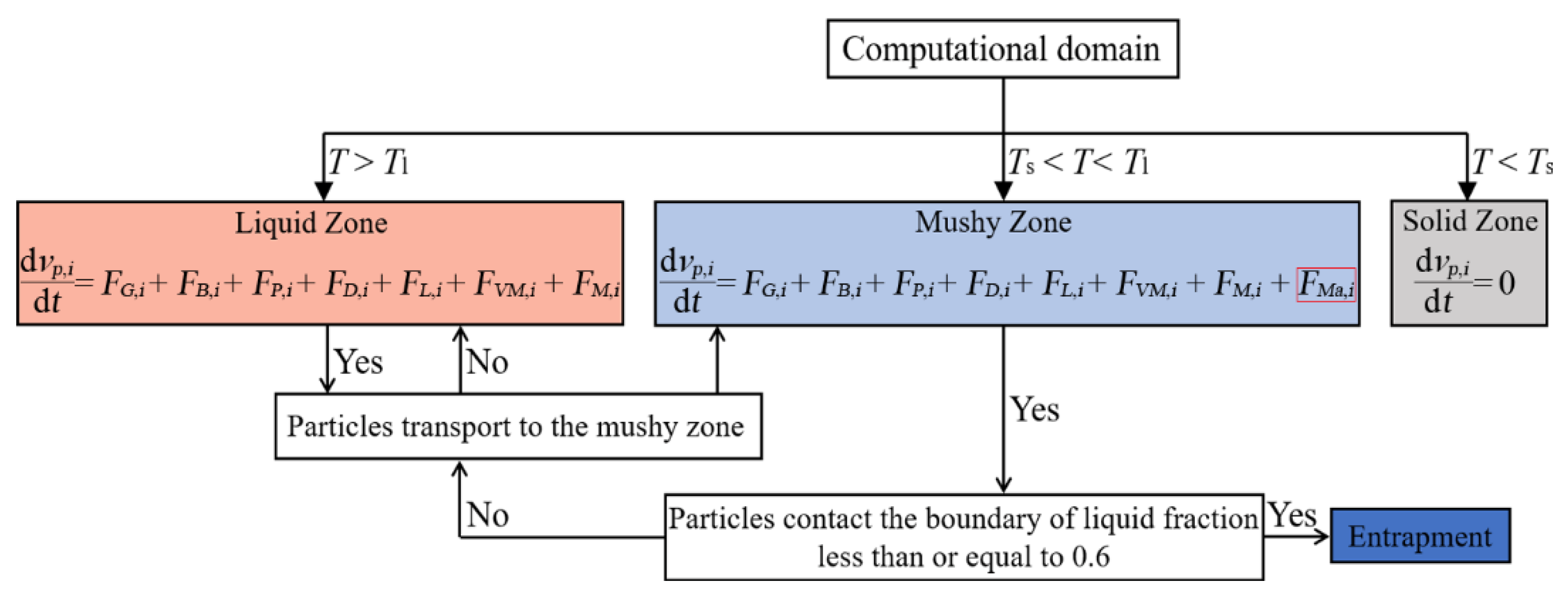
In this research, the particle-tracking technology of the discrete phase model in the CFD software is used to record the trajectory of inclusions within the mold [33,34,35]. Due to the fact that the total volume ratio of inclusions in the mold is far less than 10 percent, the uncoupled Lagrange method is adopted to solve the trajectory of the inclusions [27]. Based on this method, the following three conditions are considered to predict the motion process of the inclusions in the two thin-slab casters. The schematic diagram of the inclusion transport process is shown in Figure 5.
(1)
If the molten steel temperature T is lower than the solidus temperature Ts, there is no movement of the inclusions in the solid zone.
(2)
If the molten steel temperature T is higher than the liquidus temperature Tl, there are seven forces involved in the movement of the inclusions in the liquid zone.
(3)
If the molten steel temperature T is between the solidus temperature Ts and the liquidus temperature Tl, the inclusions penetrate into the mushy zone. In the mushy zone, except for the original seven forces, an additional Marangoni force is applied to the movement of the inclusions.
According to the above situation, the static equilibrium equation acting on the unit mass inclusions is as follows:
d v p , i d t = { 0                                                                                                   T < T s F G , i + F B , i + F P , i + F D , i + F L , i + F V M , i + F M , i                   T > T l   F G , i + F B , i + F P , i + F D , i + F L , i + F V M , i + F M , i + F M a , i    T s < T < T l
The expressions of the above seven forces can be found in the literature [27]. It should be noted that the Marangoni force involved in this study is implemented by a user-defined function (UDF). The Marangoni force is expressed as below:
F M a , i = 4 ρ p d p σ T d T d x

3.5. Electromagnetic Field Model

The magnetic induction method is utilized to solve the induced current and electromagnetic force, derived from Ohm’s law and Maxwell’s equation [11]. The induced magnetic field b is obtained through the following equation:
b i t + ( v i ) b i = 1 μ σ 2 b i + [ ( B 0 , i + b i ) ] v i ( v i ) B 0 , i
The current density is induced when the molten steel passes through the applied magnetic field B0,i. The induced current density Ji is derived from the following equation:
J i = 1 μ × B i = 1 μ × ( B 0 , i + b i )
The electromagnetic force Fm,i as an additional force in the momentum equation is stated as below:
F m , i = J i × B i = J i × ( B 0 , i + b i )

3.6. Computational Conditions

The inlet is defined as the velocity inlet, which is calculated from the casting speed to maintain flow equilibrium. The top surface is provided as a free surface and the movement of the inclusions on the free surface is set as the capture condition; that is, the inclusions can be removed after floating to the free surface [27]. The center of the mold’s wide face is a symmetrical plane, which is defined as a symmetrical condition. Electrically insulating walls are employed for the nozzle walls and the mold walls. With respect to the above-mentioned walls, a normal component of the induced current and normal gradients of other variables are set as zero [11]. In the solidification process of molten steel in the two thin-slab casters, the cooling conditions of the mold walls are regarded as heat flux condition and a convection heat exchange condition [28]. The heat transfer coefficients of the wide and narrow faces of the CSP and FTSR molds are 1500 W∙m−2∙K−1 and 1300 W∙m−2∙K−1, respectively. At the bottom of the computational domain, a fully developed flow is assumed, and normal gradients of all variables are set as zero.
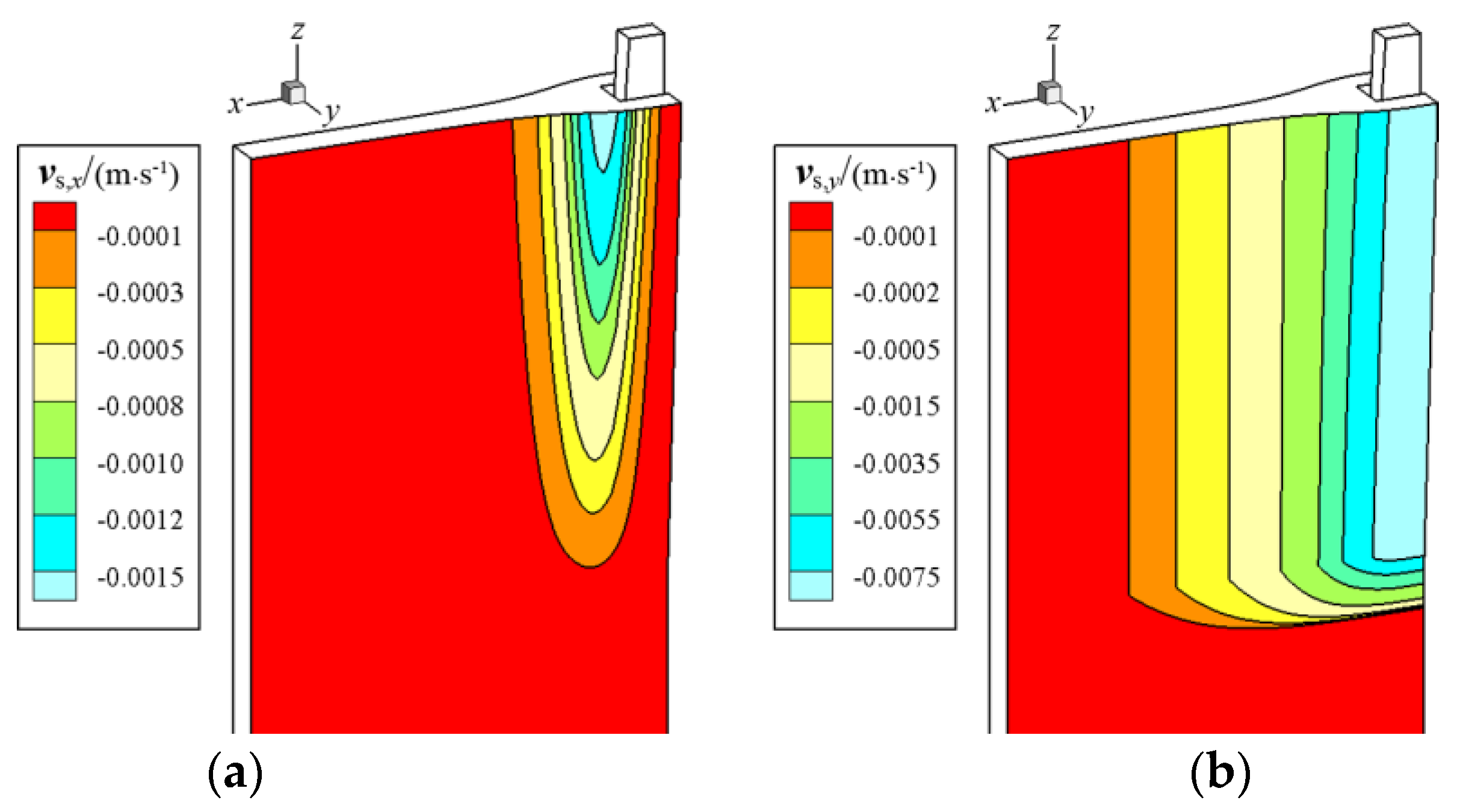
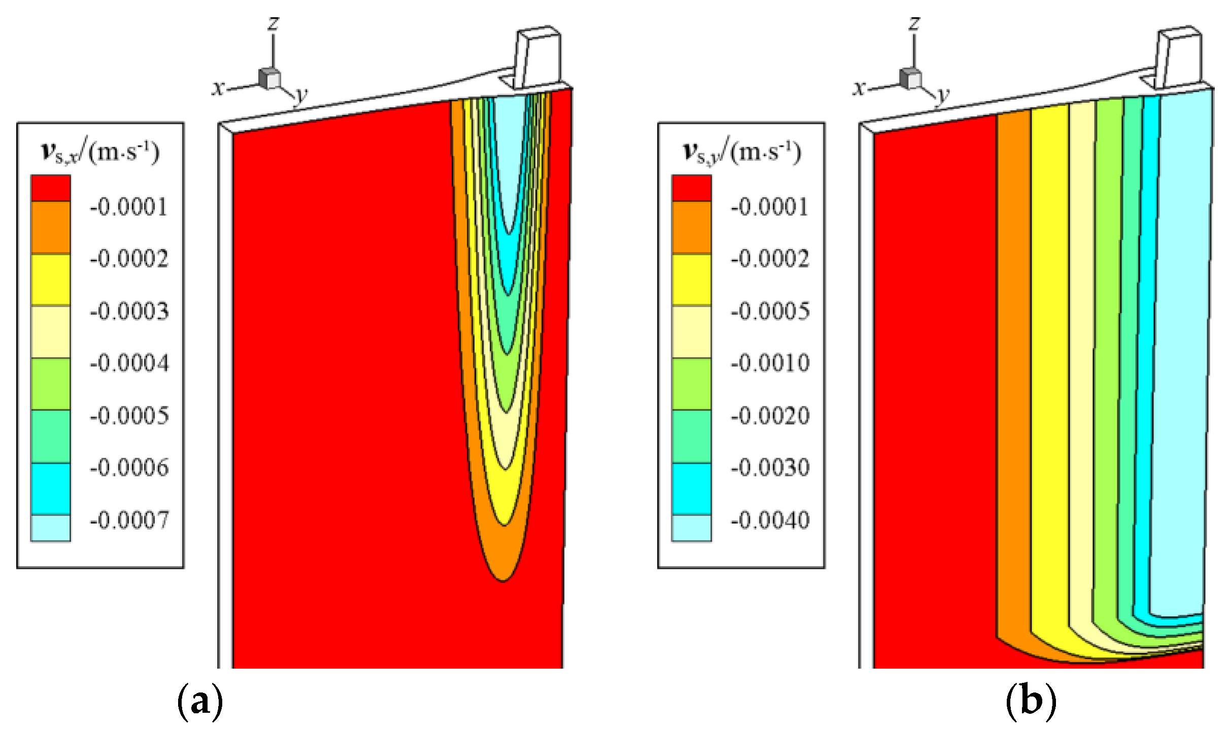
Due to the complex structure of the funnel-curved surface in the thin-slab mold, deformation, such as extrusion or stretching, can easily occur during solidification. In order to ensure that the solidified shell in the funnel region can be better formed, the shell velocity satisfies the following relationship [1,4]. In this research, the shell surface velocity distribution in the funnel region of the CSP and FTSR molds is shown in Figure 6 and Figure 7, respectively.
v s , j = | v c | n c ( n c n f ) n f | n c ( n c n f ) n f |

4. Validation

4.1. Grid Independence Test

In previous research, grid independence tests were performed to control the convergence of the solution and the quantification of the discretization errors [11,32]. In this article, the tests were carried out through three hexahedral cells. In the tests, the grid refinement factor r was regarded as a constant of 1.2, based on the grid sizes [32]. Then, the calculated convergence order can be derived from the following equation:
P = 1 ln ( r 21 ) | ln | φ 32 / φ 21 | |
where r = r 21 = r 32 , φ 21 = T 2 T 1 , φ 32 = T 3 T 2 .
The estimated relative errors δ can be obtained as follows:
δ 21 = | T 1 T 2 T 1 |
where T is the shell thickness at the mold exit along the casting direction, in mm.
Correspondingly, the grid convergence indices (GCI) of the fine and coarse grids can be given as follows [32]:
G C I f i n e 21 = 1.25 δ 21 r 21 P 1
G C I c o a r s e 21 = 1.25 δ 21 r 21 P r 21 P 1
In the same way, δ 32 , G C I f i n e 32 and G C I c o a r s e 32 can be calculated.
The statistical results of the grid independence tests are listed in Table 2. The basic parameters of the CSP and FTSR molds are as follows: a casting speed of 4.5 m/min and a magnetic flux density of 0 T. The test results indicate that the estimated relative errors of the calculated shell thickness and the GCI of the fine and coarse grids are much less than 5 percent [36]. Therefore, it can be conjectured that the calculation results used in this study satisfy the grid independence. In subsequent research, the finest mesh (M3) will be selected for numerical investigations.

4.2. Electromagnetic Field Model Verification

The electromagnetic field calculation method used in this study has been verified by the authors’ research group on the vertical electromagnetic braking (V-EMBr) mold [37]. The results of electromagnetic field measurement and numerical simulation in the V-EMBr mold are shown in Figure 8. As can be seen, the variation trend of the calculated electromagnetic field along the mold width direction is consistent with the measured results. With the use of identical geometry and parameters, the numerical results solved by the authors are in good agreement with those provided by the authors’ research group. In this article, the same mathematical model and solution method are used to solve the distribution of the electromagnetic field in the ruler EMBr mold. Therefore, it can be speculated that the numerical model adopted in this study has reasonable accuracy.

4.3. Solidification Model Verification

To validate the accuracy of the solidification mathematical model used in the current calculation, a 3D example performed by Lait et al. [38] is compared. The profile of the solidified shell in the steel billet is shown in Figure 9. As can be seen, with the use of identical geometry and parameters, the shell distribution calculated by the enthalpy porous medium method is in good overall agreement with the previous results [36,38]. Therefore, it can be considered that the method adopted in the current simulation research has relatively reasonable accuracy.

5. Results and Discussion

5.1. Electromagnetic Characteristics in the CSP and FTSR Molds with Ruler EMBr

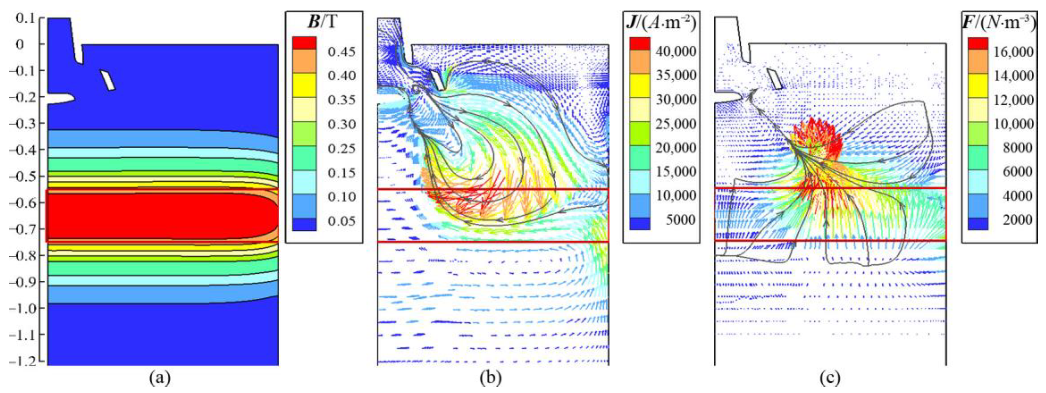
The electromagnetic characteristics in the CSP and FTSR molds are shown in Figure 10 and Figure 11, respectively. With the application of ruler EMBr, the distribution of the magnetic field in both molds decreases gradually from the center of the magnetic poles to both sides along the mold height direction. As can be seen, the magnetic field in both molds attenuates to almost zero at the top surface and mold outlet. Furthermore, it can be found that, irrespective of the CSP mold or the FTSR mold, the magnetic field is concentrated in the jet-impingement region. In this region, the induced current and electromagnetic force are, correspondingly, relatively large. In contrast, far away from this region, the induced current and the electromagnetic force in the upper and lower recirculation regions of the mold are relatively small. Hence, for the ruler EMBr applied to the CSP and FTSR molds, a major advantage of the application of horizontal magnetic poles is that the jet flow discharged from the nozzle exit can be well controlled.

5.2. Flow and Thermal Characteristics in the CSP and FTSR Molds with Ruler EMBr

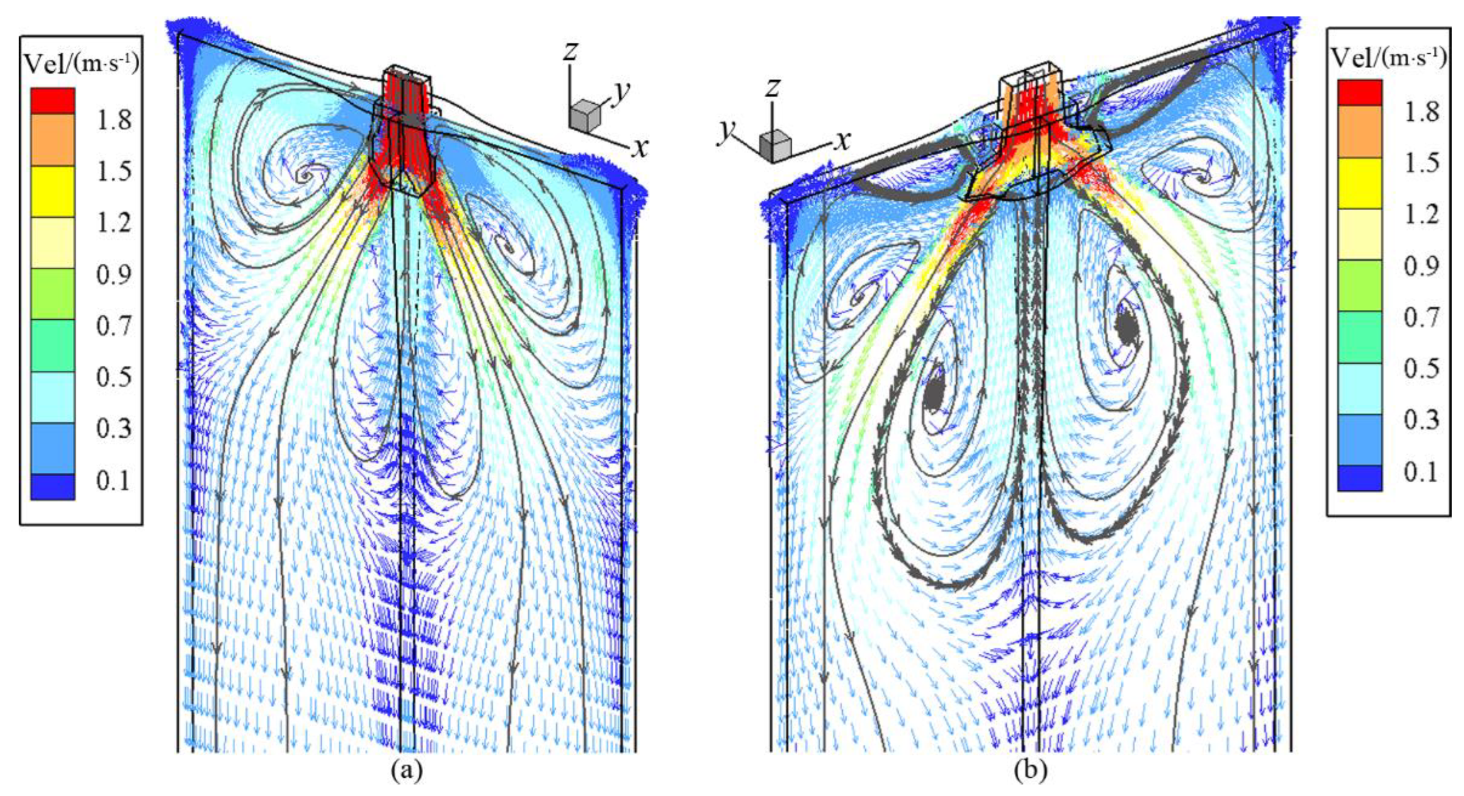
Figure 12 shows the predicted velocity vectors in the central wide faces of two molds with a casting speed of 7.5 m/min. As can be seen, due to the differences in the mold design, the SEN structure, and the SEN depth of the two molds, a different evolution of flow pattern is formed. As shown in Figure 12a, the flow characteristic of molten steel in the CSP mold is similar to those in the conventional slab mold. The molten steel discharged from the SEN forms a typical “double roll” flow pattern in the CSP mold. However, relative to the bilateral two-port SEN of the slab mold, the bifurcated SEN used in the CSP mold maintains the characteristic of a large downward port angle. In this way, the downward backflow can be constrained in a small range to avoid direct impact on the narrow face of the mold. As shown in Figure 12b, for the bilateral four-port SEN applied to the FTSR mold, on one hand, two small vortices are generated through the molten steel discharged from the upper ports of the SEN, and on the other hand, an obvious large “double roll” vortex is presented by the remaining molten steel discharged from the lower ports of the SEN.
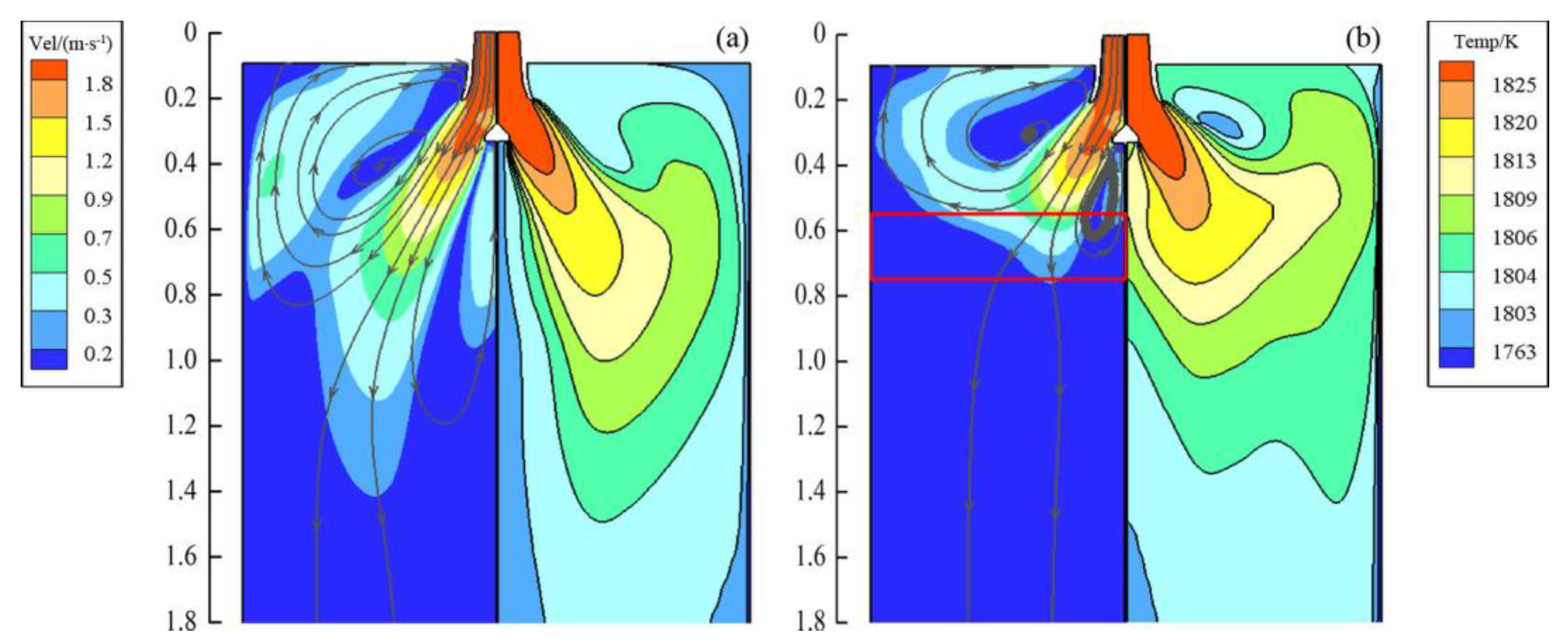
Figure 13 shows the velocity and temperature distribution in the central wide face of the CSP mold with a casting speed of 7.5 m/min. The left half of each subfigure indicates the streamlines and velocity contours. The right half of each subfigure shows the temperature contours. As shown in Figure 13a, with the absence of ruler EMBr, the high temperature molten steel discharged from the SEN penetrates deeply into the mold. Afterwards, most of the heat is consumed, and a “double roll” flow with a relatively low temperature is formed in the CSP mold. As shown in Figure 13b, with the application of ruler EMBr, when the magnetic flux density reaches 0.5 T, the jet flow discharged from the SEN is excessively inhibited by the electromagnetic force. Then, the penetration depth of the jet flow into the molten pool is significantly reduced, and an active upward backflow is formed. This is simply a consequence of mass conservation. However, the active upward backflow within the mold can successfully transport more heat to the top of the mold, which is conducive to improving the uniformity of the surface temperature of the molten steel. Moreover, the inclusions are more likely to float up to the top of the mold where they can be entrapped by mold powder.
Figure 14 shows the velocity and temperature distribution in the central wide face of the FTSR mold with a casting speed of 7.5 m/min. As shown in Figure 14a, without the ruler EMBr, two turbulent impinging jets are formed in the FTSR mold, compared with the flow pattern in the CSP mold. The impinging jet discharged from the upper ports of the SEN moves rapidly to the top surface of the FTSR mold and forms two high temperature vortices in opposite directions. The other impinging jet discharged from the lower ports of the SEN penetrates deeply into the molten pool. Afterwards, a relatively low temperature vortex appears in the upper recirculation region of the FTSR mold. This can easily cause an uneven molten steel temperature distribution in the mold. As shown in Figure 14b, in contrast, with the magnetic flux density of 0.5 T, the impact of downward backflow on the molten pool is effectively restrained. This is not only beneficial to the floating removal of inclusions, but also to the upward backflow in transporting more heat to the top surface of the FTSR mold. Accordingly, a higher molten steel temperature is obtained in the meniscus region. In addition, the slag solidification and slag rim formation therein can be avoided.
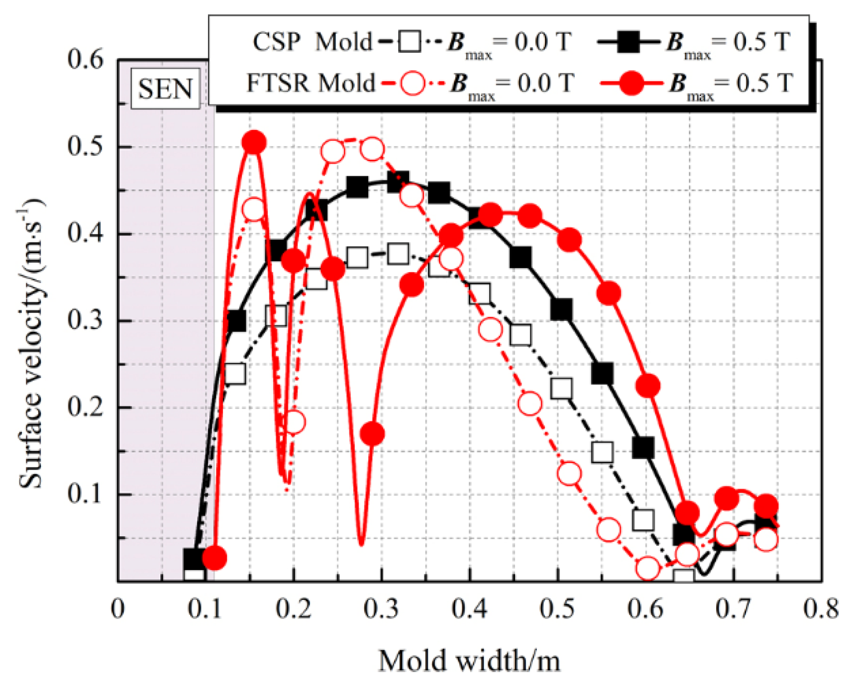
Figure 15 shows the velocity distribution on the center line of the free surface in the two molds with a casting speed of 7.5 m/min. For the FTSR mold, the impinging jet from the upper ports of the SEN forms a two-way divergent flow. Accordingly, there is an active surface flow near the upper nozzle side. A comparison of the flow features on the free surface between the two molds indicates that the surface flow in the FTSR mold is more active, due to the unique design of the upper ports of the SEN. Furthermore, with the ruler EMBr, when the magnetic flux density reaches 0.5 T, the molten steel flow on the free surface in both molds is intensified, which can also be inferred from the flow features in Figure 13 and Figure 14. As can be seen, in comparison with no EMBr, the maximum molten steel surface velocity in the CSP and FTSR molds with the ruler EMBr is increased to 0.46 and 0.51 m/s, respectively.

5.3. Level Fluctuation Characteristics in the CSP and FTSR Molds with Ruler EMBr

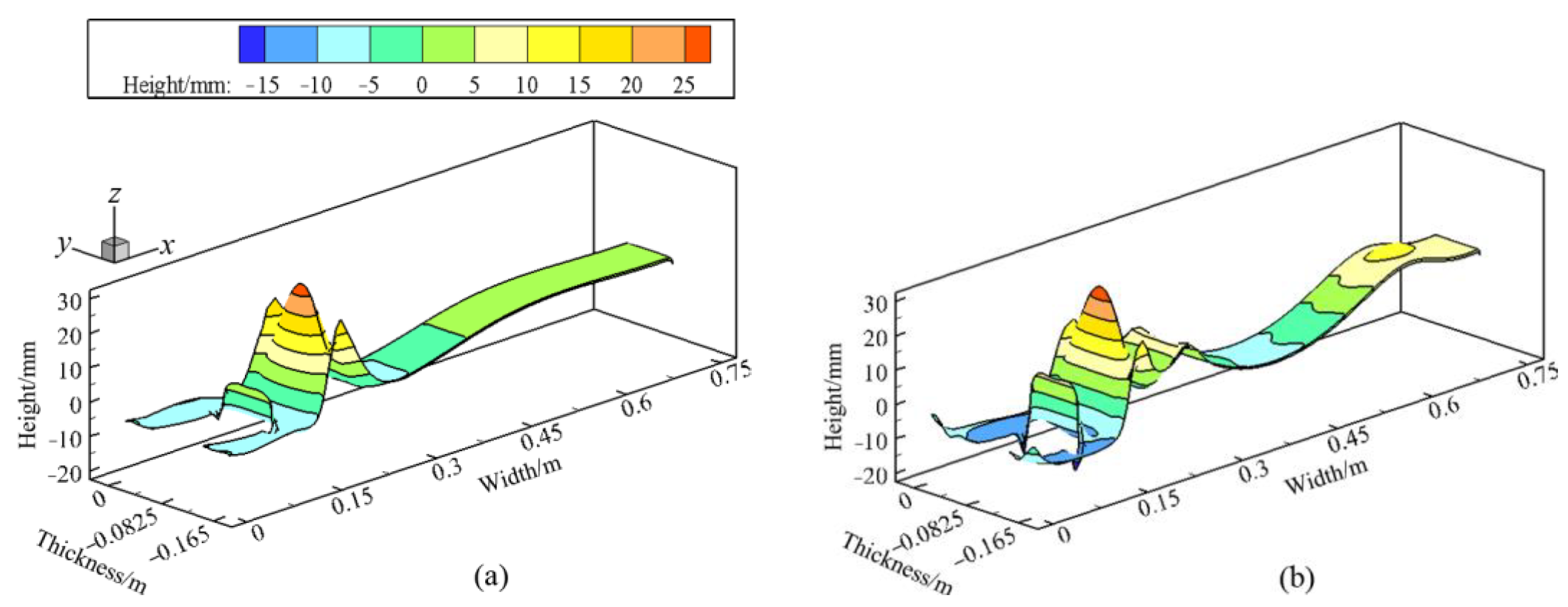
The predicted level fluctuation in the CSP and FTSR molds with a casting speed of 7.5 m/min is shown in Figure 16 and Figure 17, respectively. The level fluctuation height can be estimated by a simple potential energy balance method [1]. As can be seen, with the magnetic flux density of 0.5 T, the meniscus fluctuation in both molds is enhanced, compared to the condition without the ruler EMBr. Note that increasing the meniscus fluctuation within a reasonable range can improve slag activity and prevent slag solidification. As shown in Figure 16, the level fluctuation in the CSP mold is contributed to by the impingement of the upward backflow to the meniscus. In the meniscus region, the maximum fluctuation heights are 7.7 and 12.1 mm with the magnetic flux densities of 0 and 0.5 T, respectively. As shown in Figure 17, due to the unique design of the upper ports of the SEN, the obvious level fluctuation in the FTSR mold occurs near the upper nozzle side. In comparison with the level fluctuation in the CSP mold, the maximum level fluctuation heights in the FTSR mold significantly increase to 23.7 and 24.8 mm with the magnetic flux densities of 0 and 0.5 T, respectively.
It can be summarized from the above that to obtain a desirable level fluctuation inside the mold, the flow pattern in both molds needs to be optimized by the SEN structure, the SEN depth, the EMBr design, etc.

5.4. Solidification Features in the CSP and FTSR Molds with Ruler EMBr

Figure 18 shows the predicted growth of the solidified shells in the two molds with a casting speed of 7.5 m/min. As shown in Figure 18a, for the two high-speed thin-slab casters, the profile of shell thickness along the mold width direction is consistent with the change in the funnel-curved surface in the mold, showing a trend of decrease and, then, increase. With the application of ruler EMBr, however, the transverse diffusion of the impinging jet to the funnel-curved surface in both molds is intensified. This leads to the heat contained in the molten steel transferring rapidly to the strand surface. Due to the fact that the solidified shell growth is mainly influenced by the heat dissipated from the strand surface, the shell thickness in the funnel region is reduced. However, the shell thickness is still within the safe shell-thickness range. For instance, in the funnel region of the CSP mold, the maximum difference in the shell thickness between the magnetic flux densities of 0 and 0.5 T is only slightly reduced by 1.6 mm. As shown in Figure 18b, the difference in shell growth between the two molds is contributed to by the mold design, the SEN structure, and the SEN depth. In the jet-impingement region of the FTSR mold, the solidified shell grows slowly along the casting direction, compared with the jet-impingement region of the CSP mold. In particular, for the magnetic flux density of 0.5 T, the maximum differential shell thickness of the CSP and FTSR molds in the jet-impingement region is only slightly reduced, by 0.9 mm.

5.5. Inclusion Motion Features in the CSP and FTSR Molds with Ruler EMBr

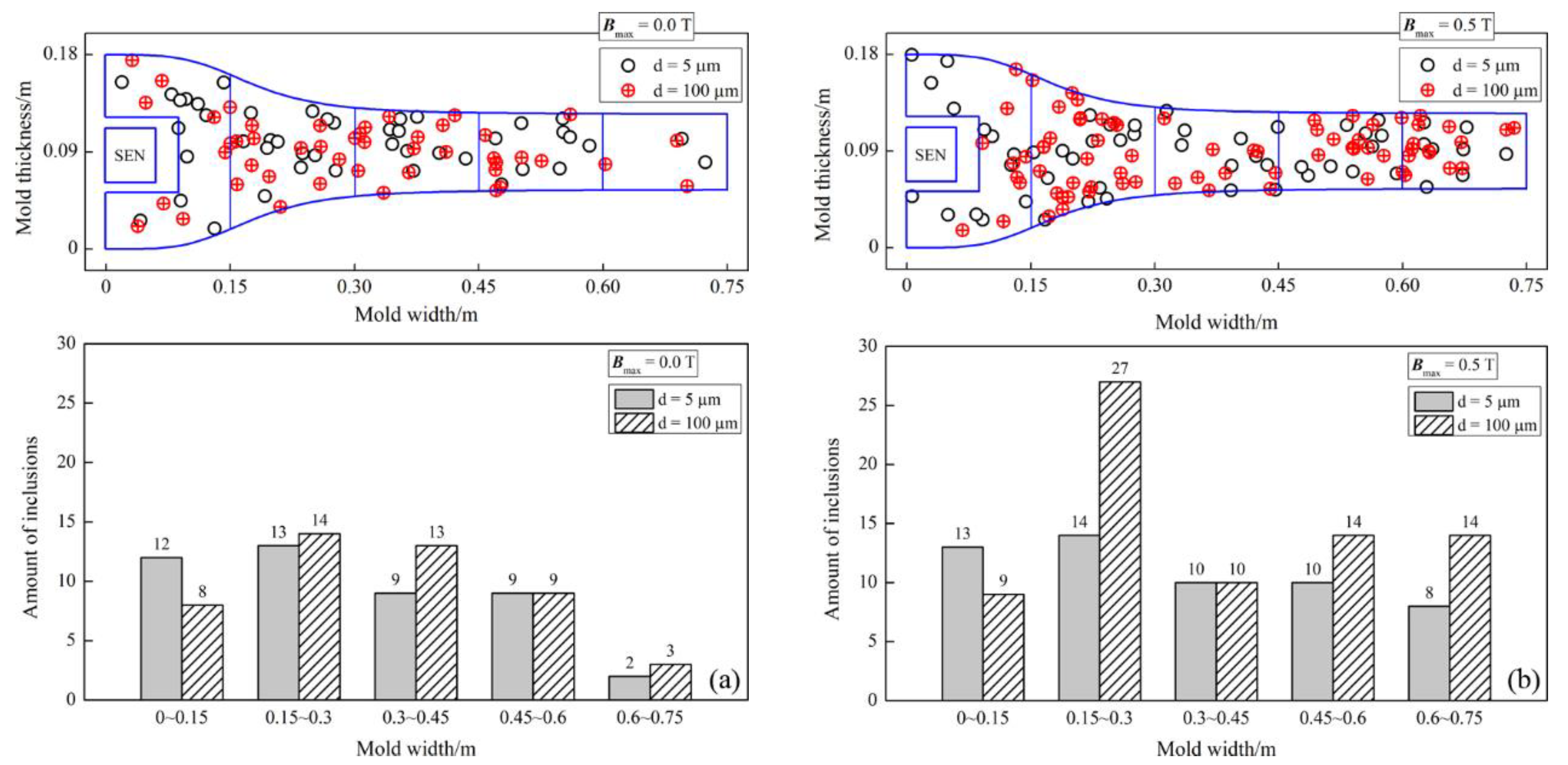
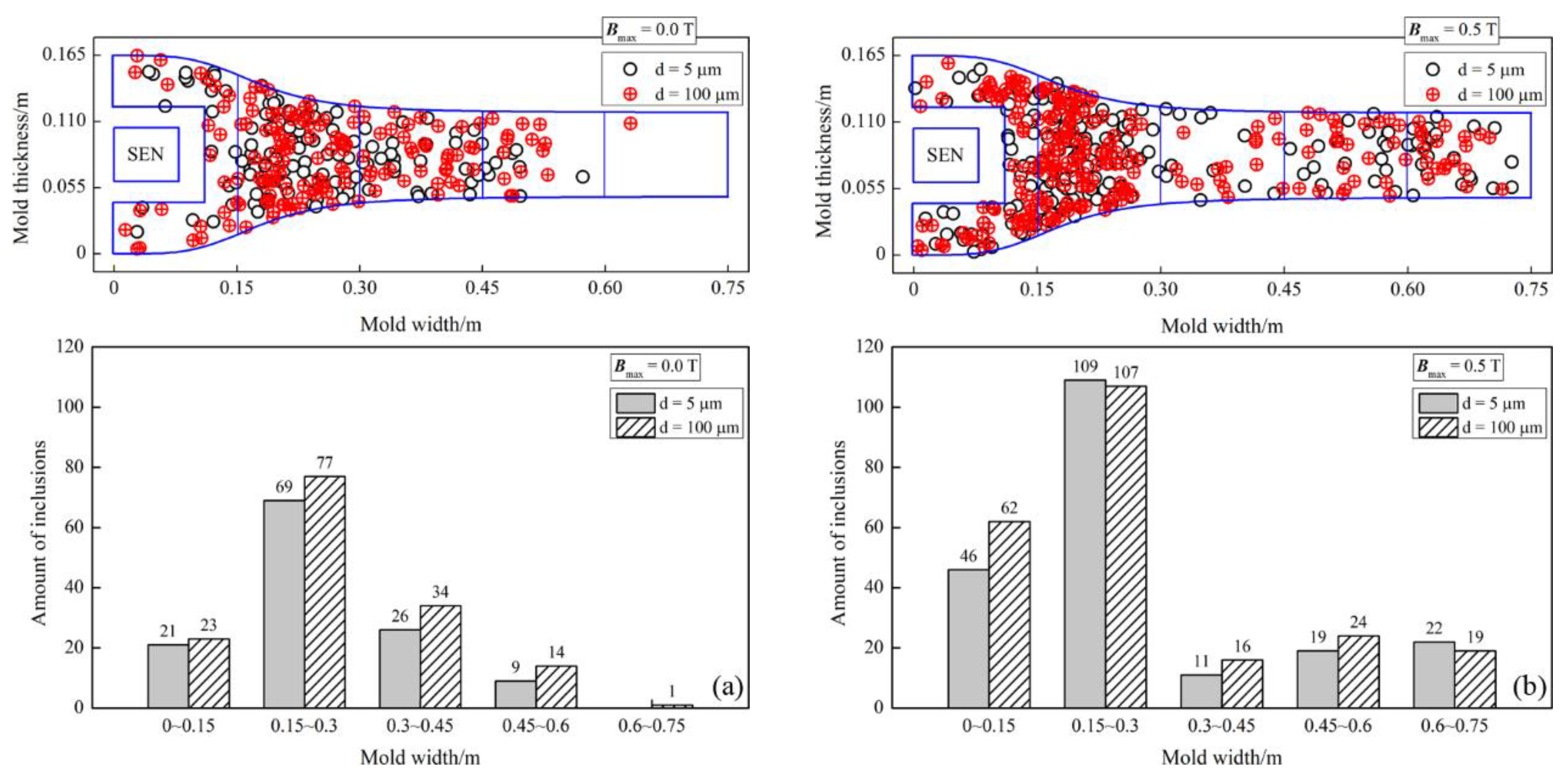
The distribution of removed inclusions on the free surface in the CSP and FTSR molds with a casting speed of 7.5 m/min is shown in Figure 19 and Figure 20, respectively. To observe the removed inclusions at different locations, the free surface is evenly divided into five regions: (1) x = 0–0.15 m, (2) x = 0.15–0.30 m, (3) x = 0.30–0.45 m, (4) x = 0.45–0.60 m, and (5) x = 0.60–0.75 m. In each region, the quantity ratios of inclusions are presented in a histogram. As can be seen, for the two thin-slab casters, the application of ruler EMBr is conducive to the inclusions floating to the free surface through the enhanced upward backflow.
As shown in Figure 19, due to the bifurcated SEN with a large downward port angle, the inclusions entrained in the molten steel penetrate deeply into the CSP mold, which increases the difficulty of the inclusions floating upward. For instance, for the magnetic flux density of 0.5 T, the floatation removal rates of inclusions with diameters of 5 and 100 μm are only 1.1 percent and 1.48 percent, respectively. In contrast, the floating removal effect of the inclusions in the FTSR mold is remarkable, as shown in Figure 20. More than half of the inclusions are removed through region 2. This indicates that the unique design of the upper ports of the SEN plays an active role in removing the inclusions from the free surface. For instance, in the case of a magnetic flux density of 0.5 T, the amount of the removed inclusions is significantly increased. The floatation removal rates of inclusions with diameters of 5 and 100 μm are increased to 4.14 percent and 4.5 percent, respectively.
To summarize, for the ruler EMBr applied to the CSP and FTSR molds, the braking effect exerted by the horizontal magnetic poles can enhance the upward backflow and the surface fluctuation. This can increase the possibility of mold flux entrapment, especially in high-speed casting. However, the favorable factors for the application of purely horizontal magnetic poles are that the temperature of molten steel near the meniscus and the floatation removal rates of inclusions are increased. This can improve the surface defects of high-speed casting products.

6. Conclusions

In the current research, the influence of the ruler EMBr device on the characteristics of the electromagnetic field, the molten steel flow, heat transfer, solidified shell growth, and inclusion movement in the two high-speed thin-slab casters was investigated through a coupled 3D mathematical model. The main conclusions were as follows.
  • With the application of the ruler EMBr, the generated magnetic field can directly act on the jet-impingement region in the CSP and FTSR molds. As a result, the excited induced current and electromagnetic force are correspondingly strengthened in this region.
  • The bifurcated SEN used in the CSP mold can lead the molten steel to the depth of the molten pool, which is not conducive to the floating removal of inclusions. With the application of the ruler EMBr, when the magnetic flux density reaches 0.5 T, the floatation removal rates of inclusions with a diameter of 100 μm in the CSP mold are only increased to 1.48 percent, when compared to the case of no EMBr.
  • The four-port SEN used in the FTSR mold is conducive to improving the uniformity of molten steel temperature distribution on the free surface and promoting the floating removal of inclusions. However, due to the unique design of the upper ports of the SEN, the intensified molten steel surface flow and fluctuation can easily lead to surface slag entrapment. With the absence of EMBr, the maximum surface fluctuation height in the FTSR mold reaches 23.7 mm at a high casting speed of 7.5 m/min.
  • With the application of the ruler EMBr in the FTSR mold, the braking effect of the ruler EMBr not only increases the molten steel temperature at the upper ports of the SEN, but also maintains the control of the jet flow discharged from the lower ports of the SEN. As a result, the penetration depth of the jet flow into the molten pool is decreased and the floating effect of the inclusions is improved accordingly. With the electromagnetic parameter of 0.5 T, the floatation removal rates of inclusions with a diameter of 100 μm in the FTSR mold are increased to 4.5 percent, when compared to the case of no EMBr.
  • For the ruler EMBr applied to the CSP and FTSR molds, the shell grows slowly in the jet-impingement region along the casting direction, resulting in a slightly thinner shell thickness. However, the shell thickness is still within the safe shell-thickness range.

Author Contributions

Conceptualization, L.X. and Q.-W.P.; validation, L.X. and Z.-F.H.; formal analysis, L.X. and Z.-F.H.; investigation, L.X., Z.-F.H., and S.Y.; writing—original draft preparation, L.X.; writing—review and editing, L.X., J.-Y.W., and Y.-T.Y.; project administration, L.X.; funding acquisition, L.X. All authors have read and agreed to the published version of the manuscript.

Funding

This research was funded by the National Natural Science Foundation of China (No. 51901095), the Natural Science Foundation of Liaoning Province (No. 2022-BS-224), and the Scientific Research Project of Liaoning Provincial Department of Education (No. LJKQZ20222282).

Data Availability Statement

Not applicable.

Acknowledgments

The authors thank the referees for their work, which greatly contributed to this article.

Conflicts of Interest

The authors declare no conflict of interest.

Nomenclature

ppressure, [Pa]FG,igravitational force, [N∙m−3]
vjsteel velocity, [m∙s−1]FB,ibuoyancy force, [N∙m−3]
μeffsteel effective viscosity, [kg∙m−1∙s−1]FP,ipressure gradient force, [N∙m−3]
gigravitational acceleration, [m2∙s−1]FD,idrag force, [N∙m−3]
Fm,ielectromagnetic force, [N∙m−3]FL,iSaffman lift force, [N∙m−3]
FT,ithermal buoyancy force, [N∙m−3]FVM,ivirtual mass force, [N∙m−3]
Smmomentum source termFM,iMagnus lift force, [N∙m−3]
Gkgeneration of turbulence kinetic energyFMa,iMarangoni force, [N∙m−3]
Sksource term
Sεsource termGreek symbols
C1coefficient
C2coefficientρsteel density, [kg∙m−3]
Smodulus of the mean rate-of-strain tensorμtturbulent viscosity, [kg∙m−1∙s−1]
Amushempirical constant in mushy regionkturbulent kinetic energy, [m2∙s−2]
Seenergy source termεturbulent dissipation rate, [m2∙s−3]
Htotal enthalpy of mushy region, [kJ∙kg−1]ηstrain rate
Ksteel thermal conductivity, [W∙m−1∙K−1]σkturbulent Prandtl number
Tsteel temperature, [K]σεturbulent Prandtl number
Tlsteel liquid temperature, [K]ξa constant of 0.001
Tssteel solid temperature, [K]
flliquid fractionSubscripts
fssolid fraction
biinduced magnetic field, [T]effeffective
B0,iapplied magnetic field, [T]Mmagnetic
vccasting speed, [m∙s−1]Tthermal
ncvector in the direction of castingmmomentum
nfnormal vector to funnel-curved surfacepparticle
vs,jfunnel-curved shell moving speed, [m∙s−1]lliquid
vp,iparticle velocity, [m∙s−1]sSolid

References

  1. Liu, H.; Yang, C.; Zhang, H.; Zhai, Q.; Gan, Y. Numerical simulation of fluid flow and thermal characteristics of thin slab in the funnel-type molds of two casters. ISIJ Int. 2011, 51, 392–401. [Google Scholar] [CrossRef] [Green Version]
  2. Zhang, L.S.; Zhang, X.F.; Wang, B.; Liu, Q.; Hu, Z.G. Numerical analysis of the influences of operational parameters on the braking effect of EMBr in a CSP funnel-type mold. Metall. Mater. Trans. B 2014, 45, 295–306. [Google Scholar] [CrossRef]
  3. Tian, X.Y.; Li, B.W.; He, J.C. Electromagnetic brake effects on the funnel shape mold of a thin slab caster based on a new type magnet. Metall. Mater. Trans. B 2009, 40, 596–604. [Google Scholar] [CrossRef]
  4. Vakhrushev, A.; Wu, M.; Ludwig, A.; Tang, Y.; Hackl, G.; Nitzl, G. Numerical investigation of shell formation in thin slab casting of funnel-type mold. Metall. Mater. Trans. B 2014, 45, 1024–1037. [Google Scholar] [CrossRef]
  5. Li, B.; Okane, T.; Umeda, T. Modeling of biased flow phenomena associated with the effects of static magnetic-field application and argon gas injection in slab continuous casting of steel. Metall. Mater. Trans. B 2001, 32, 1053–1066. [Google Scholar] [CrossRef]
  6. Kim, D.S.; Kim, W.S.; Cho, K.H. Numerical simulation of the coupled turbulent flow and macroscopic solidification in continuous casting with electromagnetic brake. ISIJ Int. 2000, 40, 670–676. [Google Scholar] [CrossRef]
  7. Qian, Z.D.; Wu, Y.L. Large eddy simulation of turbulent flow with the effects of DC magnetic field and vortex brake application in continuous casting. ISIJ Int. 2004, 44, 100–107. [Google Scholar] [CrossRef]
  8. Hwang, Y.S.; Cha, P.R.; Nam, H.S.; Moon, K.H.; Yoon, J.K. Numerical analysis of the influences of operational parameters on the fluid flow and meniscus shape in slab caster with EMBr. ISIJ Int. 1997, 37, 659–667. [Google Scholar] [CrossRef]
  9. Torres-Alonso, E.; Morales, R.D.; Demedices, L.G.; Nájera, A.; Palafox-Ramos, J.; Ramirez-Lopez, P. Flow dynamics in thin slab molds driven by sustainable oscillating jets from the feeding SEN. ISIJ Int. 2007, 47, 679–688. [Google Scholar] [CrossRef] [Green Version]
  10. Park, J.K.; Samarasekera, I.N.; Thomas, B.G.; Yoon, U.S. Thermal and mechanical behavior of copper molds during thin-slab casting (II): Mold crack formation. Metall. Mater. Trans. B 2002, 33, 437–449. [Google Scholar] [CrossRef]
  11. Xu, L.; Wang, E.; Karcher, C.; Deng, A.; Xu, X. Numerical simulation of the effects of horizontal and vertical EMBr on jet flow and mold level fluctuation in continuous casting. Metall. Mater. Trans. B 2018, 49, 2779–2793. [Google Scholar] [CrossRef]
  12. Sun, X.; Li, B.; Lu, H.; Zhong, Y.; Ren, Z.; Lei, Z. Steel/slag interface behavior under multifunction electromagnetic driving in a continuous casting slab mold. Metals 2019, 9, 983. [Google Scholar] [CrossRef] [Green Version]
  13. Garcia-Hernandez, S.; Gonzalez-Guzman, C.H.; Davila, R.M.; Barreto, J.J.; Gutierrez, E.; Calderon-Ramos, I. Modeling study of EMBr effects on the detrimental dynamic distortion phenomenon in a funnel thin slab mold. Crystals 2020, 10, 958. [Google Scholar] [CrossRef]
  14. Han, S.W.; Cho, H.J.; Jin, S.Y.; Sedén, M.; Lee, I.B.; Sohn, I. Effects of simultaneous static and traveling magnetic fields on the molten steel flow in a continuous casting mold. Metall. Mater. Trans. B 2018, 49, 2757–2769. [Google Scholar] [CrossRef]
  15. Sarkar, S.; Singh, V.; Ajmani, S.K.; Singh, R.K.; Chacko, E.Z. Effect of argon injection in meniscus flow and turbulence intensity distribution in continuous slab casting mold under the influence of double ruler magnetic field. ISIJ Int. 2018, 58, 68–77. [Google Scholar] [CrossRef] [Green Version]
  16. Cukierski, K.; Thomas, B.G. Flow control with local electromagnetic braking in continuous casting of steel slabs. Metall. Mater. Trans. B 2008, 39, 94–107. [Google Scholar] [CrossRef]
  17. Thomas, B.G.; Singh, R.; Vanka, S.P.; Timmel, K.; Eckert, S.; Gerbeth, G. Effect of single-ruler electromagnetic braking (EMBr) location on transient flow in continuous casting. J. Manuf. Sci. Prod. 2015, 15, 93–104. [Google Scholar] [CrossRef]
  18. Jin, K.; Vanka, S.P.; Thomas, B.G. Large eddy simulations of electromagnetic braking effects on argon bubble transport and capture in a steel continuous casting mold. Metall. Mater. Trans. B 2018, 49, 1360–1377. [Google Scholar] [CrossRef]
  19. Wang, Y.; Zhang, L. Fluid flow-related transport phenomena in steel slab continuous casting strands under electromagnetic brake. Metall. Mater. Trans. B 2011, 42, 1319–1351. [Google Scholar] [CrossRef]
  20. Harada, H.; Takeuchi, E.; Zeze, M.; Tanaka, H. MHD analysis in hydromagnetic casting process of clad steel slabs. Appl. Math. Modell. 1998, 22, 873–882. [Google Scholar] [CrossRef]
  21. Chaudhary, R.; Thomas, B.G.; Vanka, S.P. Effect of electromagnetic ruler braking (EMBr) on transient turbulent flow in continuous slab casting using large eddy simulations. Metall. Mater. Trans. B 2012, 3, 532–553. [Google Scholar] [CrossRef]
  22. Singh, R.; Thomas, B.G.; Vanka, S.P. Effects of a magnetic field on turbulent flow in the mold region of a steel caster. Metall. Mater. Trans. B 2013, 44, 1201–1221. [Google Scholar] [CrossRef]
  23. Zhang, L.; Wang, Y. Modeling the entrapment of nonmetallic inclusions in steel continuous-casting billets. JOM 2012, 64, 1063–1074. [Google Scholar] [CrossRef]
  24. Wang, C.; Liu, Z.; Li, B. Combined effects of EMBr and SEMS on melt flow and solidification in a thin slab continuous caster. Metals 2021, 11, 948. [Google Scholar] [CrossRef]
  25. Zhang, L.; Wang, Y.; Zuo, X. Flow Transport and inclusion motion in steel continuous-casting mold under submerged entry nozzle clogging condition. Metall. Mater. Trans. B 2008, 39, 534–550. [Google Scholar] [CrossRef]
  26. Yang, H.; Zhang, X.; Deng, K.; Li, W.; Gan, Y.; Zhan, L. Mathematical simulation on coupled flow, heat, and solute transport in slab continuous casting process. Metall. Mater. Trans. B 1998, 29, 1345–1356. [Google Scholar] [CrossRef]
  27. Liu, Z.; Li, L.; Li, B. Large eddy simulation of transient flow and inclusions transport in continuous casting mold under different electromagnetic brakes. JOM 2016, 68, 2180–2190. [Google Scholar] [CrossRef]
  28. Wang, Q.; Zhang, L. Influence of FC-Mold on the full solidification of continuous casting slab. JOM 2016, 68, 2170–2179. [Google Scholar] [CrossRef]
  29. ANSYS Inc. ANSYS Fluent User’s Guide R18; ANSYS Publisher: Canonsburg, PA, USA, 2018. [Google Scholar]
  30. Siddiqui, M.I.H.; Jha, P.K. Effect of inflow rate variation on intermixing in a steelmaking tundish during ladle change-over. Steel Res. Int. 2016, 87, 733–744. [Google Scholar] [CrossRef]
  31. Siddiqui, M.I.H.; Jha, P.K. Numerical simulation of flow-induced wall shear stresses in three different shapes of multi-strand steelmaking tundishes. Steel Res. Int. 2014, 86, 799–807. [Google Scholar] [CrossRef]
  32. Siddiqui, M.I.H.; Jha, P.K. Assessment of turbulence models for prediction of intermixed amount with free surface variation using coupled level-set volume of fluid method. ISIJ Int. 2014, 54, 2578–2587. [Google Scholar] [CrossRef] [Green Version]
  33. Chen, C.; Jonsson, L.T.I.; Tilliander, A.; Cheng, G.G.; Jönsson, P.G. A mathematical modeling study of tracer mixing in a continuous casting tundish. Metall. Mater. Trans. B 2015, 46, 169–190. [Google Scholar] [CrossRef]
  34. Chen, C.; Jonsson, L.T.I.; Tilliander, A.; Cheng, G.G.; Jönsson, P.G. A mathematical modeling study of the influence of small amounts of KCl solution tracers on mixing in water and residence time distribution of tracers in a continuous flow reactor-metallurgical tundish. Chem. Eng. Sci. 2015, 137, 914–937. [Google Scholar] [CrossRef]
  35. Chen, C.; Ni, P.Y.; Jonsson, L.T.I.; Tilliander, A.; Cheng, G.G.; Jönsson, P.G. A model study of inclusions deposition, macroscopic transport, and dynamic removal at steel-slag interface for different tundish designs. Metall. Mater. Trans. B 2016, 47, 1916–1932. [Google Scholar] [CrossRef]
  36. Aboutalebi, M.R.; Hasan, M.; Guthrie, R.I.L. Coupled turbulent flow, heat, and solute transport in continuous casting processes. Metall. Mater. Trans. B 1995, 26, 731–744. [Google Scholar] [CrossRef]
  37. Li, Z.; Wang, E.; Xu, Y. Behavior of molten steel flow in continuous casting mold with different static magnetic field configurations. J. Iron Steel Res. Int. 2018, 25, 366–377. [Google Scholar] [CrossRef]
  38. Lait, J.E.; Brimacombe, J.K.; Weinberg, F. Mathematical modeling of heat flow in the continuous casting of steel. Ironmak. Steelmak. 1974, 1, 90–97. [Google Scholar]
Figure 1. Schematic diagram of ruler EMBr device: (a) the geometric model of the ruler EMBr device and (b) the dimensions of the ruler EMBr device.
Processes 10 02738 g001
Figure 2. Schematic diagram of computational domain and mesh: (a) CSP mold and (b) FTSR mold.
Processes 10 02738 g002
Figure 3. Schematic diagram of submerged entry nozzle of the CSP mold: (a) the geometric model of the SEN and (b) the dimensions of the SEN.
Processes 10 02738 g003
Figure 4. Schematic diagram of submerged entry nozzle of the FTSR mold: (a) the geometric model of the SEN and (b) the dimensions of the SEN.
Processes 10 02738 g004
Figure 5. Schematic diagram of particle transport process in the CSP and FTSR molds.
Processes 10 02738 g005
Figure 6. Schematic distribution of shell surface velocity on the funnel region of the CSP mold: (a) X-velocity and (b) Y-velocity.
Processes 10 02738 g006
Figure 7. Schematic distribution of shell surface velocity on the funnel region of the FTSR mold: (a) X-velocity and (b) Y-velocity.
Processes 10 02738 g007
Figure 8. Distribution of magnetic flux density along the mold width direction.
Processes 10 02738 g008
Figure 9. Comparison between the predicted shell thickness and experimental measurements.
Processes 10 02738 g009
Figure 10. Electromagnetic characteristics in the central plane of the CSP mold: (a) magnetic flux density, (b) induced current density, and (c) electromagnetic force.
Processes 10 02738 g010
Figure 11. Electromagnetic characteristics in the central plane of the FTSR mold: (a) magnetic flux density, (b) induced current density, and (c) electromagnetic force.
Processes 10 02738 g011
Figure 12. Characteristics of molten steel flow field in the mold: (a) CSP mold and (b) FTSR mold.
Processes 10 02738 g012
Figure 13. Velocity (left half of each subfigure) and temperature (right half of each subfigure) distribution of molten steel in the central plane of the CSP mold thickness: (a) Bmax = 0 T and (b) Bmax = 0.5 T.
Processes 10 02738 g013
Figure 14. Velocity (left half of each subfigure) and temperature (right half of each subfigure) distribution of molten steel in the central plane of the FTSR mold thickness: (a) Bmax = 0 T and (b) Bmax = 0.5 T.
Processes 10 02738 g014
Figure 15. Effect of magnetic flux density on molten steel surface velocity in the two casters.
Processes 10 02738 g015
Figure 16. Effect of magnetic flux density on level fluctuation in the CSP mold: (a) Bmax = 0 T and (b) Bmax = 0.5 T.
Processes 10 02738 g016
Figure 17. Effect of magnetic flux density on level fluctuation in the FTSR mold: (a) Bmax = 0 T and (b) Bmax = 0.5 T.
Processes 10 02738 g017
Figure 18. Effect of magnetic flux density on solidified shell thickness in the two casters: (a) at the mold exit on the mold wide face and (b) at the center line on the mold narrow face.
Processes 10 02738 g018
Figure 19. Inclusion distribution on the free surface in the CSP mold: (a) Bmax = 0 T and (b) Bmax = 0.5 T.
Processes 10 02738 g019
Figure 20. Inclusion distribution on the free surface in the FTSR mold: (a) Bmax = 0 T and (b) Bmax = 0.5 T.
Processes 10 02738 g020
Table 1. Parameters of the CSP and FTSR molds.
Casting Parameters of the CSP Mold
ParameterValueParameterValue
Mold size1500 mm × 70 mmMold length1100 mm
Maximum thickness180 mmSEN angle port−50°
SEN depth255 mmCasting speed4.5, 7.5 m∙min−1
Casting parameters of the FTSR mold
Mold size1500 mm × 70 mmMold length1200 mm
Maximum thickness165 mmInlet cross section145 mm × 44 mm
SEN depth225 mmCasting speed4.5, 7.5 m∙min−1
Properties of molten steel
Steel density7020 kg∙m−3Solidus temperature1763 K
Steel viscosity0.0062 Pa∙sLiquidus temperature1803 K
Specific heat720 J∙kg−1∙K−1Thermal expansion coefficient0.0001 K−1
Thermal conductivity27 W∙m−1∙K−1Solidification latent heat272 kJ∙kg−1
Properties of inclusions
Specific heat860 J∙kg−1∙K−1Inclusions density5000 kg∙m−3 [25]
Inclusions diameter5, 100 μmNumber of inclusions10,000
Electromagnetic parameters
Electric conductivity7.14 × 105 S∙m−1Magnetic flux density0.5 T
Magnetic permeability1.257×10−6 H∙m−1Relative permeability1000
Table 2. Simulation error statistics of solidified shell thickness.
Error statistics of Solidified Shell Thickness in the CSP Mold
MeshM1M2M3
Hexahedral cells number430,000650,000940,000
Shell thickness/Ti12.43 mm12.26 mm12.22 mm
Relative error/δ1.37 percent0.33 percent
Fine grid convergence index/GCIfine0.53 percent0.13 percent
Coarse grid convergence index/GCIcoarse2.24 percent0.54 percent
Error statistics of Solidified Shell Thickness in the FTSR Mold
MeshM1M2M3
Hexahedral cells number540,000860,0001300,000
Shell thickness/Ti12.64 mm12.56 mm12.51 mm
Relative error/δ0.63 percent0.40 percent
Fine grid convergence index/GCIfine1.31 percent0.83 percent
Coarse grid convergence index/GCIcoarse2.10 percent1.33 percent
Note: Computed shell thickness is positioned at the center line on the mold narrow face.
Publisher’s Note: MDPI stays neutral with regard to jurisdictional claims in published maps and institutional affiliations.