1. Introduction
Today, our demand for energy and fuel is increasing. Compared with other fossil energy sources, China is rich in coal reserves, but the direct utilization of coal has many problems, such as high gangue mineral content and moisture content, low calorific value and environmental pollution. In the traditional combustion process, the minerals in coal are mostly discharged from the boiler or particle control device in the form of ash or discharged into the atmosphere as particulate matter. Coal combustion causes various environmental problems, such as particulate matter, SOx, NOx, greenhouse gas and toxic metal emissions. Due to these problems in the direct utilization of coal, coal upgrading has become a top priority.
Ultra-clean coal (UCC) refers to clean coal with little inorganic content after coal is processed by physical or chemical methods. UCC has potential application value. It can not only be directly burned but also used in solid fuel cell power generation systems [
1]. In addition, syngas produced from UCC is a high-quality energy source, and hydrogen in syngas can be used as a hydrogen source for efficient power generation. It is also the raw material for synthesizing high-value-added chemicals and coal-based liquid fuels.
Rahman et al. [
2] proposed UCC chemical chain combustion with CuO as an oxygen carrier. Using UCC as fuel to solve the problems of ash deposition and oxygen carrier pollution, chemical chain combustion will become an effective way for the clean utilization of coal in the future [
3]. Kopyscinski [
4,
5] compared the steam gasification of UCC with and without a catalyst (K
2CO
3); the gasification rate of UCC under the catalytic condition increased 10 times, and the activation energy decreased by about 100 KJ/mol. Scholars have found that adding UCC to 1/3 coking coal can obtain the best thermoplastic and improve tensile strength [
6,
7]. A large number of studies have shown that UCC is feasible as a fuel. The ash deposition after UCC combustion will lead to a decline in cell efficiency. This is because the ash contains sulfur and has strong corrosivity, which will significantly reduce the service life of cell materials [
8,
9,
10]. In addition, UCC is also of great significance in the production of clean micronized coal water fuel, activated carbon and carbon-based materials [
11].
UCC shows excellent performance both as fuel and coal-based materials. It is imperative to prepare UCC in terms of the large demand for coal-based materials in the future and the requirements of environmental protection. Therefore, it is urgent to find an effective method to prepare UCC.
As is well known, the coal structure is complex. In order to obtain the ideal UCC with high carbon content, it is necessary to remove the moisture, minerals and harmful substances from the coal. In recent years, researchers have conducted a lot of research on the preparation of UCC [
12,
13,
14,
15,
16,
17]. The processing methods of UCC can be divided into physical processing and chemical processing. Physical processing can be divided into flotation, gravity separation, electromagnetic separation and other processing methods according to different processing principles [
18,
19,
20]. Chemical processing can be divided into acid–base impregnation and solvent extraction [
21,
22,
23,
24,
25].
Steel et al. [
13] used HF and HNO
3 to reduce the ash content of bituminous coal to 0.6%. Jorjani et al. [
22] successfully prepared UCC by the microwave pretreatment of raw coal with the power of 900 W followed by the treatment of HF-HNO3, but HF is highly corrosive and difficult to realize in industrial application. Japan’s New Energy and Industrial Technology Development Organization used solvent extraction to prepare UCC and develop a method for its application in power generation systems [
8,
26]. Wijaya [
27] designed a high-temperature and high-pressure acid process to prepare UCC as fuel for gas turbines based on the characteristics of Australian lignite. The preparation of UCC by the chemical method is very effective, but the economic benefit is poor, the cost is relatively high, and the energy consumption is high. Therefore, in order to separate inorganic minerals from coal, more and more researchers are considering advanced physical separation methods. Among these methods, the most promising one is flotation [
28,
29].
In order to prepare UCC, raw coal must be ground into very fine particles so that the inorganic minerals in raw coal can be separated from coal. However, when the flotation feed particle is too fine, it will lead to an increase in reagent consumption and a decrease in collector selectivity in the flotation process, resulting in the high ash content of flotation-cleaned coal. Flint [
30] believed that particles are not conducive to flotation because the bubbles generated by conventional flotation are too large to make small particles adhere.
Some scholars have tried to gasify the collector to improve the flotation results of minerals. Liu et al. [
31] designed an oil bubble flotation device and used it in the flotation of silica, galena and sphalerite. The results show that the oil bubble flotation technology can significantly improve the recovery of minerals. In addition, Zhou et al. [
32] used this device to conduct the flotation of bastnaesite, and the results show that the active oil bubble technology can be used to improve the flotation effect of bastnaesite, but it is very important to select an appropriate collector to make the active oil bubble for the flotation effect. Zhou et al. [
33] also demonstrated that the hydrophobic force of the oil bubble surface is much higher than that of an ordinary bubble surface by extending the DLVO theory. Wallwork et al. [
34] studied the application of oil bubble flotation technology in oil sand ore purification. The test results show that, compared with the traditional flotation process, the recovery rate of oil bubble flotation was increased by about 80%, and the total recovery rate was close to 100%. Xia et al. [
35] studied the application of gasification collector flotation technology in oxidized coal. Compared with conventional flotation, this method can significantly improve the flotation recovery of oxidized coal.
In recent years, with the increase in environmental protection, clean and efficient utilization of coal has become the goal of the long-term development of coal. Because of the high demand for coal-based materials in the future and the high-quality requirements of environmental ecology, it is imperative to develop UCC. Therefore, it is urgent to find an effective method to prepare UCC. At present, the main method for preparing UCC is the chemical method. However, the acid and alkali used in the process of preparing UCC by the chemical method severely corrode the equipment and cause certain damage to the coal-based structure, resulting in high energy consumption in the preparation process. In this study, firstly, coal particles and associated minerals were fully separated by grinding, and then UCC was separated by the collector gasification flotation method.
2. Materials and Methods
2.1. Coal Samples and Reagents
The long-flame coal used in the test was obtained from Inner Mongolia, China. The proximate analysis result of coal sample is presented in
Table 1.
Due to the high content of raw coal ash, the density composition of raw coal and the ash content and yield of each density grade product were investigated through floating and sinking experiments, and the appropriate density grade product was selected as the raw coal for preparing UCC. The floating and sinking test results are shown in
Table 2. It can be seen from
Table 2 that the ash content of coal samples with −1.3 g/cm
3 and 1.3–1.4 g/cm
3 density grade was low, so coal sample with −1.4 g/cm
3 density was selected as the test sample in this study. Analytical-grade MIBC (methyl isobutyl carbinol) and dodecane were used as frother and collector, respectively. Analytical grade benzene with a density of 0.8 g/cm
3 and carbon tetrachloride with a density of 1.6 g/cm
3 were used to make a heavy liquid with a density of 1.4 g/cm
3.
2.2. XRD (X-ray Diffraction) Measurement
Because the ash content of the test coal sample was low and the carbon content was high, the coal sample had to be ashed at 300 °C before the test to improve the detection accuracy of inorganic minerals in the coal sample. Test conditions: Cu target radiation source (λ = 0.15418 nm), the tube voltage was 40 kV, the tube current was 100 mA, the scanning range was 2.5°–70°, the rate was 4°/min, and the step was 0.02°. Jade 6.0 software was used to analyze the spectrogram and judge the phase composition of the tested sample.
2.3. SEM-EDS Measurement
The FlexSEM1000 scanning electron microscope (Hitachi, Tokyo, Japan) was used to observe the apparent morphology of the sample particles under low vacuum. The American IXRF Model 550i Energy Dispersion Spectrometer (EDS) combined with SEM was used to analyze the element composition on a certain “point, line or surface” of the particle surface. The peak value of each element was used to semi-quantitatively analyze the relative content of its elements.
2.4. Specific Surface Area and Pore Structure Measurement
The specific surface analyzer is an instrument used to measure the specific surface area, pore structure and other properties of solid samples. Its basic principle is to obtain the specific surface area, pore volume and other information of the measured samples according to different calculation models by measuring the amount of gas adsorbed and desorbed according to the specific surface free energy of the solid surface for adsorbing certain substances. The specific surface area and pore structure of coal were determined by ASAP 2020 specific surface analyzer. Nitrogen was the adsorbate, and the adsorption temperature was 77.4 K (liquid nitrogen temperature). The sample was evacuated at 300 °C for 12 h before nitrogen adsorption test.
2.5. Grinding Experiment
In order to obtain UCC, it is necessary to ensure the full dissociation of coal and high-ash-gangue minerals. Therefore, a wet drum ball mill was used to treat the samples, and the particle size and density composition of the grinding products were analyzed. The concentration of grinding sample was 30%, the speed of ball mill was 200 r/min, and the grinding time was 10 min, 20 min and 30 min, respectively.
2.6. Experiment System
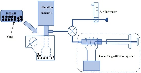
The collector gasification flotation method is shown in
Figure 1. The test system was mainly composed of two parts: conventional mechanical stirring flotation machine and collector gasification system. The charging pipe of the flotation machine was connected to a three-way valve. One end of the three-way valve was connected to the air flow meter, and the other end was connected to an aerator. The vaporized collector was mixed with the air through the three-way valve and was sucked into the flotation machine by the charging pipe of the flotation machine with the help of the negative pressure generated by the rotation of the impeller, so as to realize the mixing with the pulp in the impeller area. Since the boiling point of n-dodecane is 216.3 °C, the temperature of the vaporizer was set to 300 °C so that the collector was vaporized instantly. The flow rate of N
2 was 20 mL/min.
2.7. Flotation Method
All flotation tests were carried out using a 150 mL XFG flotation cell. Since the content of fine particles in the sample was high, in order to weaken the mechanical entrainment, the flotation pulp concentration was set to 60 g/L. Coal sample was first prewetted in flotation cell for 2 min. For the traditional flotation process, the collector was added to the flotation cell at one time and conditioned for 2 min, while for the collector gasification flotation method, the reagent was continuously passed into the flotation cell after vaporization, lasting for 5 min. The impeller speed of flotation machine was 1800 r/min, and air flow rate was 0.3 L/min. Each flotation test was performed for 5 min.
3. Results and Discussion
3.1. Mineral Composition Analysis
The XRD analysis results of the coal samples are shown in
Figure 2. It can be seen from
Figure 2 that the main gangue minerals contained in the samples were montmorillonite and kaolinite, both of which were clay minerals and easy to slime. During the flotation process, it is easy to cause fine mud entrainment, enter the foam layer to affect the ash content of clean coal and increase the consumption of flotation reagents.
3.2. Effect of Grinding Time on Particle Size Distribution and Mineral Dissociation
The effect of grinding time on coal particle size distribution is presented in
Figure 3. It can be seen from
Figure 3 that with the increase in grinding time, the D90 and D[4,3] of the grinding products gradually decreased. When the grinding time was 20 min, the D90 and D[4,3] of the grinding products were 5.20 um and 4.23 um, respectively. While the grinding time continued to increase to 30 min, the D
90 and D[4,3] of the grinding products increased. According to
Figure 3, with the increase in grinding time, the particle size distribution curve gradually moved to the left, indicating that the fine particles gradually increased. However, when the grinding time was 30 min, there were two peaks in the particle size distribution curve of the grinding products. This was due to the continuous increase in the specific surface area and surface energy of the fine particles, which leads to the enhancement of the surface activity of the particles and the increase in the interaction force between the particles and finally leads to the agglomeration of the coal particles.
The full dissociation of the coal matrix and minerals is the key link and prerequisite for preparing ultrapure coal. Generally, the smaller the particle size of ultra-fine coal is, the fuller the mineral dissociation is. However, with the decrease in the particle size of grinding products, the energy consumption required for grinding is higher. Moreover, too-small particles will also lead to a poor flotation effect. On the one hand, the collision and adhesion probability between the particle and the agent molecule will be reduced. Secondly, with the decrease in particle size, its surface area increased continuously, and more reagent molecules were adsorbed on its surface, resulting in an increase in flotation reagent consumption. In addition, the fine clay minerals in the coal sample, such as kaolinite, will enter the cleaned coal through mechanical entrainment, causing an increase in ash content. Therefore, it is necessary to analyze the density composition of grinding products to determine the best grinding time.
The products under different grinding times were respectively subject to floating and sinking tests, and the ash content and yield of −1.3 g/cm
3 density grade materials were tested and calculated.
Table 3 shows the ash content and yield of −1.3 g/cm
3 density grade particles in the products under different grinding times. It can be seen from
Table 3 that the ash content of floats was less than 1% when the grinding time was 20 min, indicating that the coal and minerals have been fully dissociated. When the grinding time increased to 30 min, the ash content of the floats increased slightly, which was caused by the agglomeration between the fine coal particles, and some high-ash minerals were wrapped into the aggregates. Therefore, the grinding time was set as 20 min.
3.3. Changes in Particle Surface Properties
In the solid adsorption–desorption experiment, the adsorption curve and desorption curve of the adsorption isotherm will overlap and separate. When the two curves are separated, an adsorption loop will be formed. The shape of the adsorption loop can reflect the shape and structure of the coal mesopore. It can be seen from
Figure 4 that the adsorption curve and desorption curve of the coal sample do not coincide, indicating that the sample was mainly composed of open and breathable pores. It can also be seen from
Table 4 that with the increase in grinding time, the specific surface area and pore volume of coal samples gradually increased, while the pore diameter gradually decreased. This was because larger pores were destroyed by mechanical force and gradually formed micropores, and micropores have larger pore volumes, which lead to a decrease in the average pore diameter and increase in the pore volume of the samples.
The increase in the specific surface area of coal particles will lead to an increase in reagent consumption, and the increase in micropores in coal particles on the coal surface will lead to the enhancement of pore water absorption capacity. These pores were easy to fill with water during flotation, which will increase the degree of hydration on the surface of coal particles, increase the thickness and stability of the hydration film and reduce the floatability of ultra-fine particles. Therefore, it is difficult to obtain ideal results by using traditional coal slime flotation methods.
3.4. Flotation Results
The flotation results of the collector gasification flotation method and traditional flotation method under different collector dosages are shown in
Figure 5. It can be seen from
Figure 5 that under a low reagent dosage, the clean coal yield of the collector gasification flotation method was lower than that of the traditional flotation method. With the increase in collector dosage, the clean coal yield of the collector gasification flotation method gradually exceeded that of the traditional flotation method. This was because at a low reagent dosage, the collector needs to enter the flotation cell through the pipeline after being gasified at a high temperature. Some gaseous collectors were adsorbed by the pipeline, resulting in less collector actually entering the flotation cell. Therefore, at a low collector dosage, the clean coal yield of the collector gasification flotation method was lower than that of the traditional flotation method.
When the traditional flotation method was adopted, the collector was added to the flotation cell at one time, while when the collector gasification flotation method was adopted, the collector was added to the flotation cell continuously in the form of gas. When the collector was added to the flotation cell at one time, some reagent molecules were adsorbed on the surface of gangue minerals, which improved the floatability of gangue minerals and led to the increase in the ash content of flotation-cleaned coal. Some reagent molecules were directly transferred to the foam layer without interaction with coal particles, resulting in a decrease in reagent concentration in the flotation cell, and the flotation-cleaned coal yield is lower than that of the traditional flotation method.
It can also be seen from
Figure 5 that the ash content of clean coal obtained by the collector gasification flotation method was always lower than that obtained by the traditional flotation method under the whole reagent dosage, indicating that the collector gasification flotation method has higher selectivity. Theoretically, when a complete collector monolayer is adsorbed on the mineral surface, its contact angle should be maximum. For coal, since the surface of coal particles is naturally hydrophobic, good flotation results can be obtained as long as the surface of coal particles is covered by collector molecules in local areas. In order to improve the selectivity of the flotation process and reduce the consumption of reagents, the deficient dosage flotation system should be adopted; that is, with the continuous consumption of collector in the flotation process, the collector should be added to the flotation cell in time to maintain the lowest reasonable concentration required in the pulp. It can be seen from
Figure 5 that when the collector dosage was 2.0 kg/t, the yield of clean coal obtained by the collector gasification flotation method was 4.1% higher than that by the traditional flotation method, while the ash content of clean coal was 0.3% lower.
Compared with the traditional flotation process, in the collector gasification flotation process, reagents were added to the flotation cell in gaseous form, and the reagent molecules were preferentially adsorbed on the gas–solid interface, which improved the hydrophobicity of the particle surface and thus improved the yield of cleaned coal. On the other hand, the adsorption of a gaseous collector on a solid surface is selective. Because the surface of coal particles is hydrophobic, and the interaction force between coal particles and gaseous collector molecules is larger, the gaseous collector preferentially condenses and is adsorbed on the surface of particles with high hydrophobicity. Therefore, compared with the traditional flotation method, the collector gasification flotation method has higher selectivity.
3.5. Flotation Results
The SEM image of flotation-cleaned coal is presented in
Figure 6. The EDS analysis results of the flotation-cleaned coal surface are shown in
Table 5. It can be seen from
Figure 6 and
Table 5 that the flotation-cleaned coal was essentially composed of finely dissociated organic matter particles, as shown in Particle 1 and Particle 2. Particle 1 was mainly composed of C and O elements, while Particle 2 contained not only C and O elements but also a certain amount of Al and Si elements. Al and Si are the main elements of kaolinite, indicating that there was a certain amount of kaolinite in the flotation-cleaned coal. This part of kaolinite mainly entered the flotation-cleaned coal by the way of mechanical entrainment and fine covering.


