Abstract
Recent environmental concern has been raised about the development of biocomposites because of their low cost, eco-friendliness, and biodegradability. Machining of polymeric composite is inevitable during assembly of structural components. In view of creating holes in structural composites, drilling is necessary and it is essential to carry out research to find the optimal machining parameters. The experimental assessment and prediction of the thrust force and torque involved in drilling composites reinforced with sheep horn are presented in this work. The matrix and sheep horn particles were combined in the right proportions before being moulded and poured into a mould, then allowed to cure at room temperature. Investigated properties included ultimate tensile strength, flexural strength, and hardness. To evaluate the quality of the hole, micrographs of the drilled hole were employed. When the mixture was optimised based on the properties, it was found that a 70:30 ratio produced the best results. Thrust force and torque of 58 N and 4.8 N-mm, respectively, were observed for sheep horn filler laminates which were drilled using the combination of 6 mm diameter, 0.1 mm/rev feed rate, and 400 rpm speed. This is by far the best among the combinations used in the experiment. Additionally, the experimental outcomes indicate that the feed rate and spindle speed are the most significant factors affecting the thrust force. Since there were minimal errors in the comparison, the central composite design modelling is consummate. Overall, the extensive experimental effort offers several options to utilise this composite material in future applications across a wide range of fields.
1. Introduction
Due to their characteristics and applications, natural fibre composites are now receiving greater attention in research than composites based on synthetic fibres [1,2,3]. Natural fibres are superior to synthetic fibres in a number of ways, including great flexibility, environmental friendliness, low specific gravity, high impact resistance, reduced abrasiveness on equipment, and inexpensive cost [4,5,6]. Animal-based fibre composite materials have only recently been used because of their ability to be combined with polymers with higher melting temperatures due to their thermal behaviour [7,8]. By altering the amounts of horn fibre, Kumar et al. [9] studied the mechanical and thermal characteristics of horn fibre-reinforced polypropylene composites (5, 10, 15, and 20 wt. percent). The tensile strength of horn fibre-reinforced polypropylene composites is greater than that of pure polypropylene. The performance of the horn fibre/polypropylene composites, which include 15% horn fibre, was good. The percentage of elongation at break decreased, the impact strength and ultimate tensile strength both increased noticeably, and yield strength only slightly, the tensile modulus increased by 15.74 percent, the flexural strength by 16.95%, the flexural modulus by 59.69%, and the flexural strength by 16.95%. The thermogravimetric analysis’s findings show that when the fibre content is increased, horn fibre/polypropylene composites become more thermally stable. For structural applications, Tajammul Hussain et al. [10] studied the mechanical and physical characteristics of sheep horn from the indigenous Deccani breed in Karnataka, India. Under ambient (dry) and rehydrated (wet) conditions, longitudinal and transverse specimens from the horn were selected. The results were consistent with those for the yield strength of 53.5 ± 6.5 MPa, which was higher than its peers, and the maximum compressive stress of 557.75 MPa, the Young’s modulus of 6.5 ± 0.5 GPa, the density corresponding to a biopolymer of 1.2 g/cc, anticipated to be the lightest among its competitors, the flexural strength of 168.75 MPa, with the lowest failure strain percentage of 6.5 ± 0.5, and the Rockwell hardness value of 60 HRB seem the best in this cadre.
Michael et al. [11] investigated the mechanical properties of the horn keratin of the bighorn sheep (Ovis canadensis) in relation to the impacts of water and microstructure. According to the findings, anisotropy, position along the horn, and the type of loading condition had less of an impact on the mechanical behaviour of sheep horn than the moisture content. The transverse elastic modulus, yield strength, and failure strain were determined to be 2.9 GPa, 37 MPa, and 2%, respectively, under the ambient dry environment (10 wt.%). Jhonson et al. [12] investigated how moisture, anisotropy, stress, and strain rate impact the mechanical properties of the keratin in the horn of bighorn sheep. The horns are formed of fibrous keratin tubules that span the length of the horn inside an amorphous keratin matrix. Under both ambient dry (10 wt.% water) and rehydrated (35 wt.% water) conditions, the samples were tested in tension and compression. The material’s stress state-dependent characteristics were shown to change with increased moisture content, and it was also found to improve ductility and decrease strength. The horn keratin differs significantly from other keratins in that it displays greater energy absorption in the hydrated state as well as significant strain rate dependence in both tension and compression. Cow horn particle-reinforced epoxy resin composites with varying filler percentages (5, 10, 15, 20, 25, 30, 35, and 40 wt%) and particle sizes of 100 and 150 m made using the manual layup approach were examined by Ambali et al. [13]. The study’s findings showed that the tensile properties of the filler increased to a particular level and then reduced when cow horn was added. The flexural and impact characteristics of the polymers were simultaneously improved by the insertion of the fibre in a random order. A unique composite consisting of varying percentages of sheep hair reinforced in epoxy resin using a hand layup process was an effort by Raghavendra et al. [14]. The matrix to reinforcement ratios of 100:0, 90:10, 80:20, and 75:25 were all taken into consideration. The study’s findings indicated that the created composite had a high level of mechanical and electrical resistance. The effectiveness of cement matrix–plastic tiles with laterite and cow horn as additives was investigated by Kehinde et al. [15]. Cement matrix–plastic tiles were made using laterite, cow horn, sand, plastic, and a specified amount of water, and the proportions of cement, sand, and plastic stayed constant. The resulting mixture was compressed at a 25 kN compaction pressure. The size of the created sample was 150 × 150 × 15 mm. After compaction, the specimen was put through a performance test, and the results were improved. Vacuum-assisted resin infusion moulding was used by Kochan et al. [16] to make biocomposites utilising discarded mussel shells (coarse and fine powder) as reinforcement. These composites’ mechanical behaviour was evaluated in line with ASTM standards. Mohankumar et al. [3] carried out similar research using different ratios of powder reinforcements including coconut shell powder, walnut shell powder, and wood apple powder. Menandro et al. [17] examined the characteristics of composites made by reinforcing a matrix using chicken feathers (barbs and rachis). The study took into account a number of composite boards with various ratios of waste feathers, cement, sand, and chemical admixtures. When feathers made up between 5 and 20 percent of the weight, the workable combination significantly decreased. In terms of strength and dimensional stability, boards with 5 to 10 wt.% fibre showed similarities with wood fibre–cement composites. The proportions considerably lowered the elasticity modulus, increased water absorption, and raised rupture modulus when the percentage of feathers climbed over 10% of the weight. For natural fibre composites, which behave quite differently from conventional metallic materials, machining is a crucial parameter [18]. Keratin lamellae are sporadically spaced apart throughout the length of the horn’s tubules to form the structure of sheep horns. The resultant structure, which is made of fibrous keratin and is laminated in three dimensions, has a porosity gradient that runs across the thickness of the horn [19]. α-Keratin is a structural, fibrous protein found in sheep horns. The smallest amino acids, glycine and alanine, are highly concentrated in α-keratin. As cysteine is present, the keratin molecules are kept together by H-bonding and disulfide cross-linked bonds. Disulfide bridges increase the structure’s stiffness and aid in keratin’s insoluble nature [20]. The assembling of functional components occasionally requires the machining of natural fibre-reinforced polymer composites. Due to the need to manufacture bolt or rivet holes, drilling is very important. This machining process is known for producing numerous damage types in the composite materials generated, including delamination, fibre pull-outs, and inter-laminar crack propagation [21]. This is due to an inaccuracy in hole roundness. The drilling process characteristics that significantly affect the operation include spindle speed, feed rate, drill geometry, and material properties. The rotation speed and feed rate are important variables in influencing the hole defaces among the several drilling parameters [22]. Drilling natural fibre composites presents a variety of challenges, such as dimensional variation, high temperature distribution, surface delamination, material disintegration, etc. Drilling increases the thrust force in the machining region and the inner wall’s surface roughness [23]. Drilling thrust force, which directly affects the quality of the drilled hole, is the main factor in the machinability of laminated composites [24]. The correct machining parameters must be used in order to minimise thrust force and burr [25]. Depending on the performance, optimisation is a key stage in choosing the appropriate process parameters. The Taguchi method, the finite element method, the gradient search method, and artificial neural networks are only a few optimisation strategies [26]. Response surface methodology (RSM), a technique proposed as an appropriate statistical tool to design and optimise the examined process, is used for the experimental design and analysis [27,28,29]. Natural fibre composite would be easier to machine if control factors including tool shape, tool material, cutting parameter, and machining environment were improved [30]. The literature on drilling properties with fibre/particle-reinforced composites made of animal waste products includes very few findings. In this context, preparing composites with sheep horn particles in different ratios, such as 80:20, 75:25, and 70:30, is the focus of this work in order to evaluate their drilling characteristics and mechanical properties. Composite specimens were prepared in accordance with the ASTM standards as described in Section 2. In this experimental study, the statistical response surface methodology (RSM)-based Box–Behnken design was selected for evaluation of the effect of different parameters (spindle speed, feed rate, and drill diameter) and their interactions on the thrust force and torque. Finally, the experimental data were validated against the predicted value.
2. Materials and Methods
The horns from subadult (1.5–2.0 years old) and healthy sheep (Deccani breed; Ovis canadensis) were obtained within 24 h after slaughter from a local slaughter house (use: dietary reasons; Hanur Taluk, Chamarajanagara District, Karnataka, India). Raw horns were dried for 24 h. The samples were then soaked in water for a period of about 96 h. Then, the horn fibres were dried in sunlight for 3 days. After the horn fibres were completely dried, the horn was converted into fine particles using a grinding machine. Using sieve analysis, the grain sizes were segregated. Fine powder particles with a size of 106 μm were chosen for the study. Sheep horn is environmentally friendly, biodegradable, abundant, renewable, and cheap with low density.
2.1. Fabrication of Composites
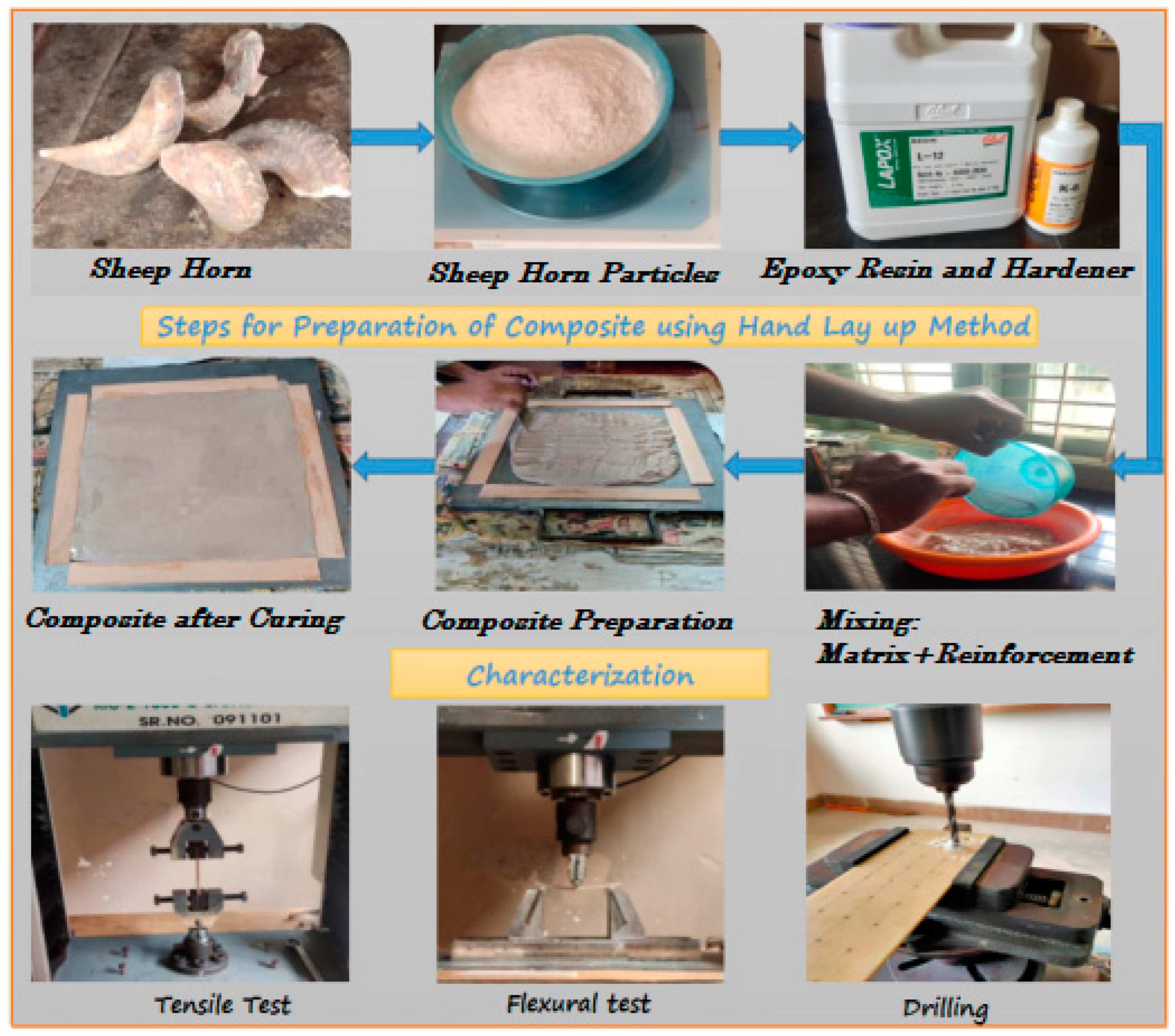
As reinforcement, sheep horn powder was employed and epoxy resin (Lapox L-12) and hardener K-6 were employed as the matrix. The composites were fabricated using a hand layup process [31] and had dimensions of 300 × 300 × 4 mm and three distinct matrix and reinforcement ratio compositions were selected. Matrix to reinforcements proportions of 70:30, 75:25, and 80:20 were considered in the study. Three samples were fabricated in each category. The resin and hardener mix of 10:1 proportions was used. Initially, the surface plate was cleaned to remove dust and dirt from the surface. A die of 300 × 300 × 4 mm was prepared using wood sticks. The bottom surface was coated with thinner and Waxpol, to prevent sticking of composite to the surface. Thoroughly mixed matrix material and reinforcements with known proportions were uniformly poured into the mould. Ensuring complete filling of the die with the mixture, the die was closed with the upper surface plate and some weights were placed on it for proper moulding and it was left to dry for 3–4 h at room temperature. The experimental procedure is described in Figure 1.
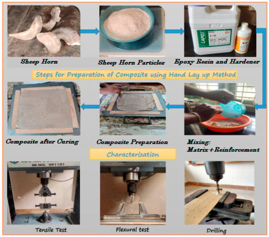
Figure 1.
Experimental procedure.
2.2. Characterisation
2.2.1. Mechanical Tests
The sheep horn particle-reinforced composites were tested with tensile, flexural, and Rockwell hardness tests. For each test, three samples were tested, and average results were taken into account. According to ASTM D638, the tensile test was carried out using a universal testing machine (KIC-2-1000-C with a capacity of 100 kN, make: Kalpak Instruments and Controls, Pune). The specimens were prepared in accordance with ASTM D790-98 for the flexural test. Each test was carried out until the failure occurred. A Rockwell hardness tester was used to measure the prepared composites’ hardness in accordance with ASTM D785. Using a diamond indenter (C Scale) and an applied load of 100 kg, the hardness test was carried out [32].
2.2.2. Drilling Process
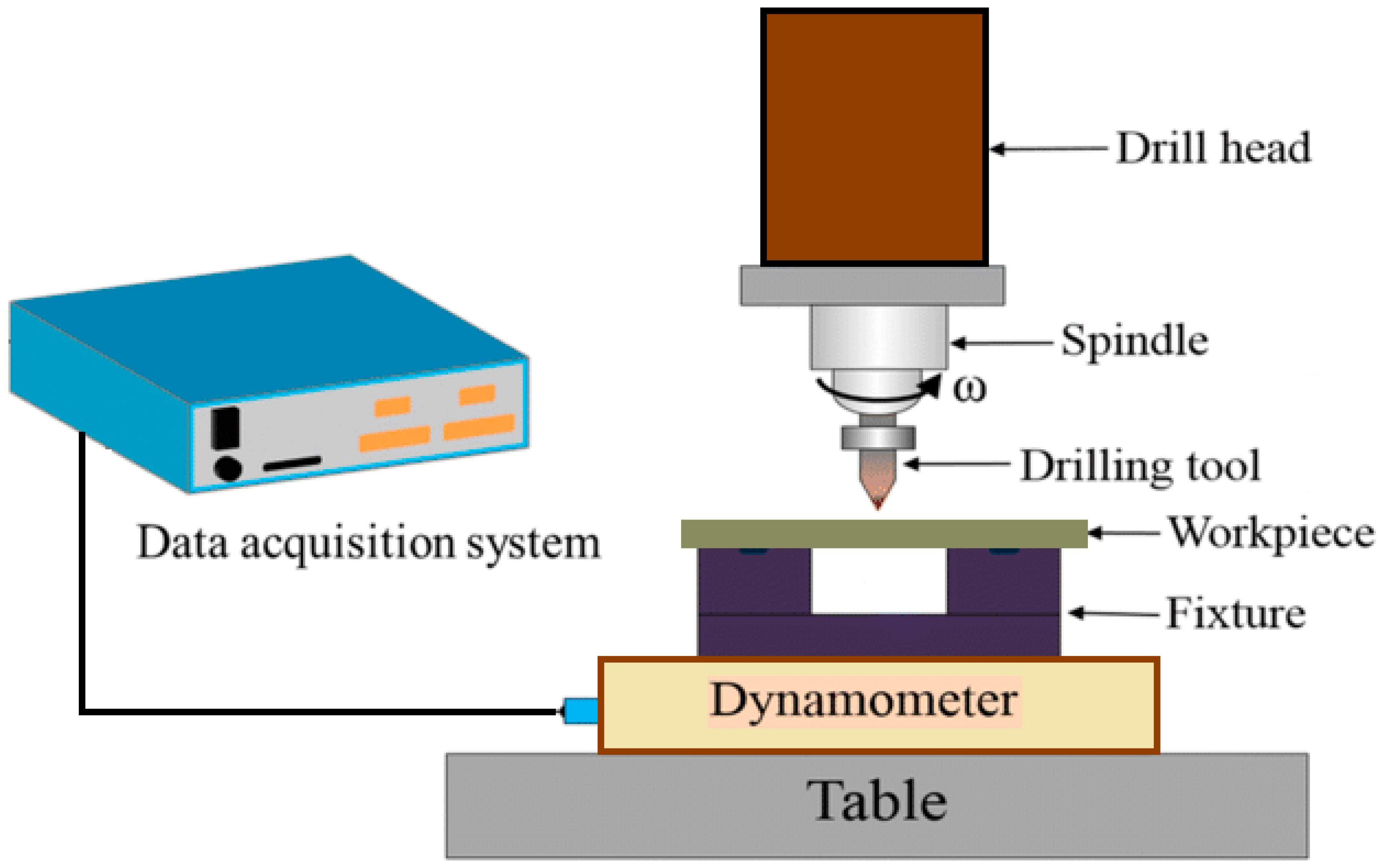
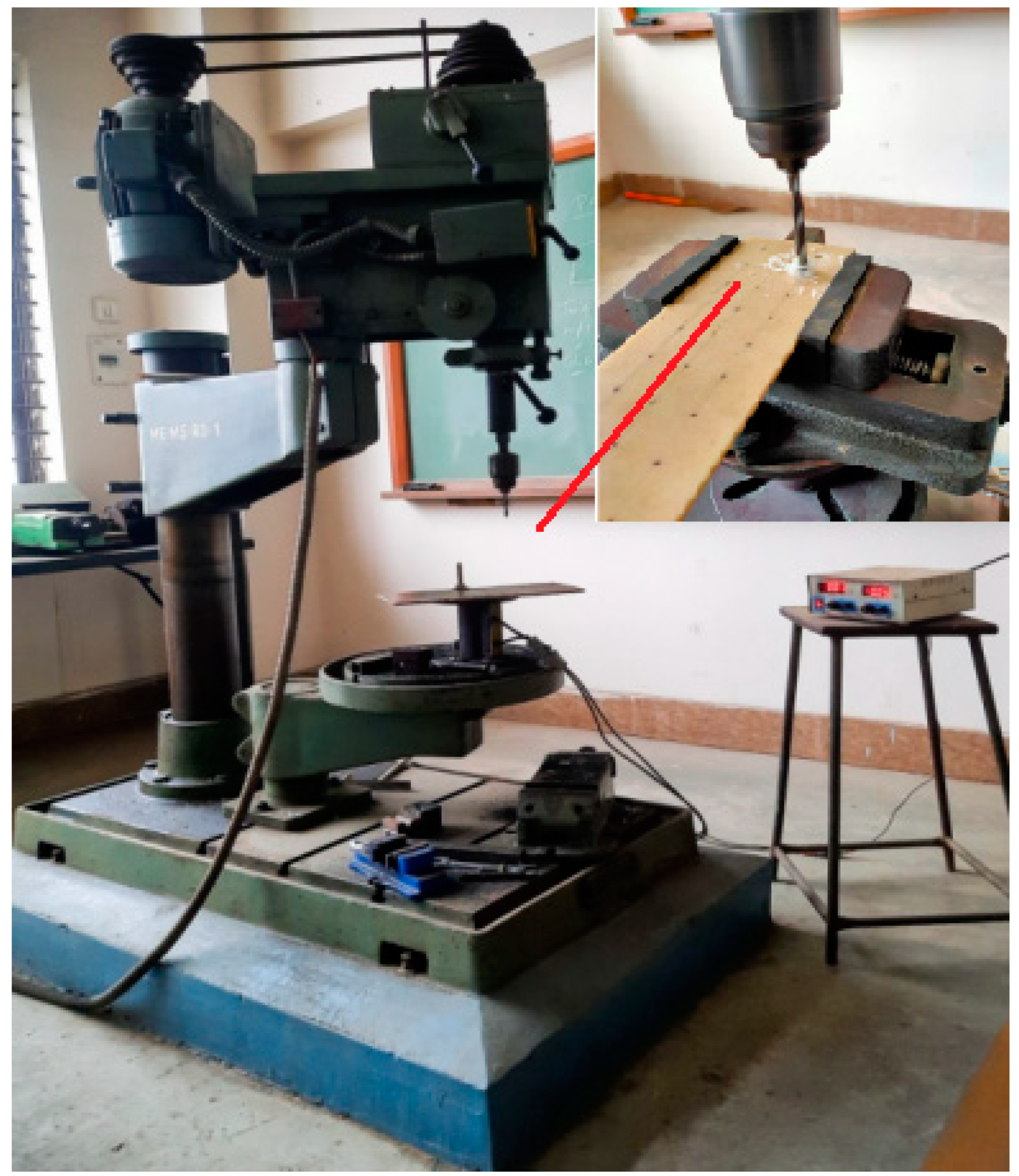
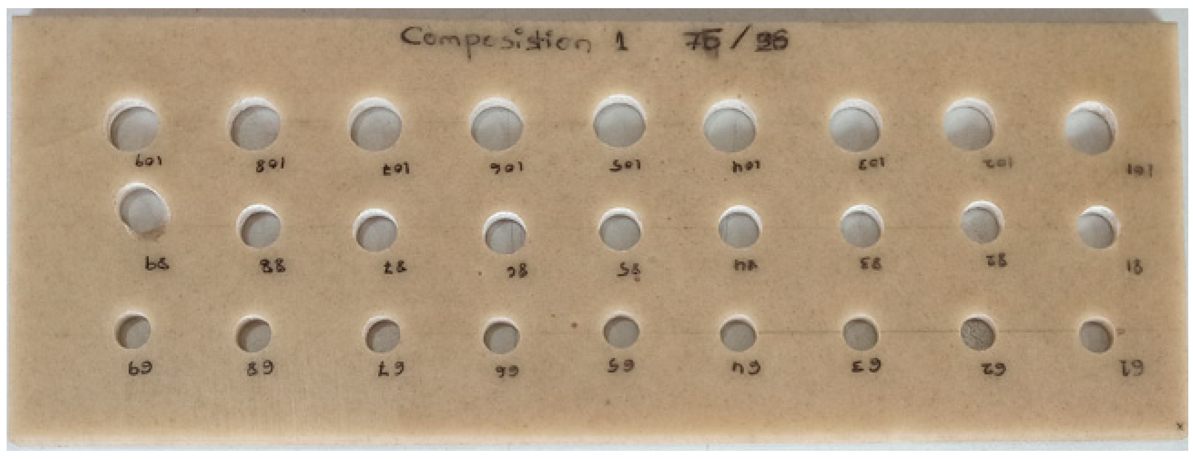
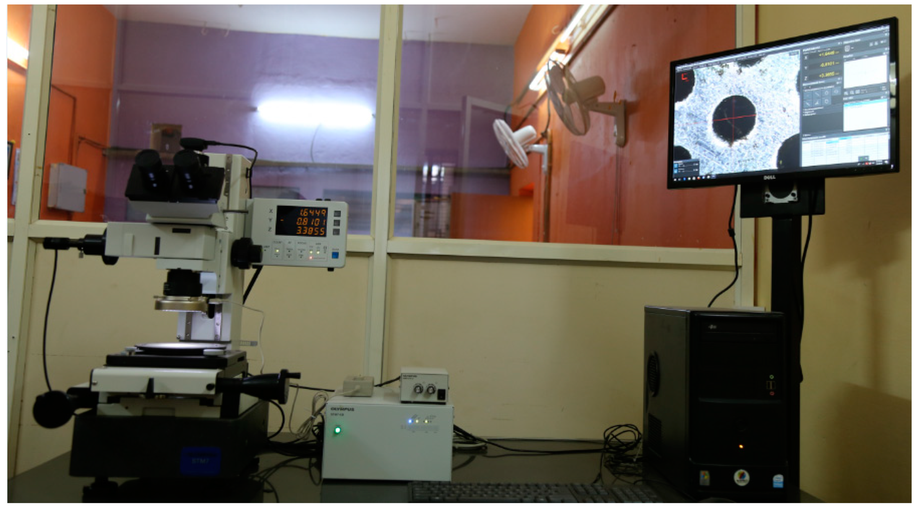
Three different spindle speeds, feed rates, and three different HSS drill bit diameters—6 mm, 8 mm, and 10 mm—were used for the drilling process. A piezoelectric dynamometer was used to measure the thrust forces experienced during drilling. A controller unit transferred and processed the signal, which was then recorded on a data collecting system. The experimental setup is shown in Figure 2. Figure 3 refers to the actual drilling setup with a dynamometer on a sheep horn particle-reinforced composite plate. Composites with drilled holes as per Design of Experiments (DOE) are shown in Figure 4. Hole quality was assessed using light microscopy as shown in Figure 5.
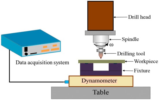
Figure 2.
Experimental setup.
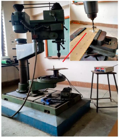
Figure 3.
Actual setup of drilling operation with dynamometer.
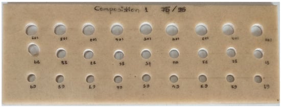
Figure 4.
Fabricated composite with different diameter holes.
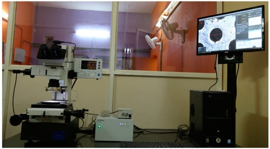
Figure 5.
Light microscope used for hole quality assessment.
2.3. Design of Experiments
The appropriate control parameters were used to produce an experimental design. The different levels of HSS drill bit sizes, feed rates, and spindle speeds were chosen. The experimental plan for the control factors made use of the L27 orthogonal array that is presented in Table 1. For each test, the combination of control variables at various levels is shown in Table 2. According to DOE, 27 experiments were conducted to determine how drilling parameters and drill diameter effect thrust force and torque as well as for parameter optimisation.

Table 1.
Factors and their level combination for drilling.

Table 2.
Experimental design using L27 orthogonal array.
3. Results and Discussion
3.1. EDS Analysis
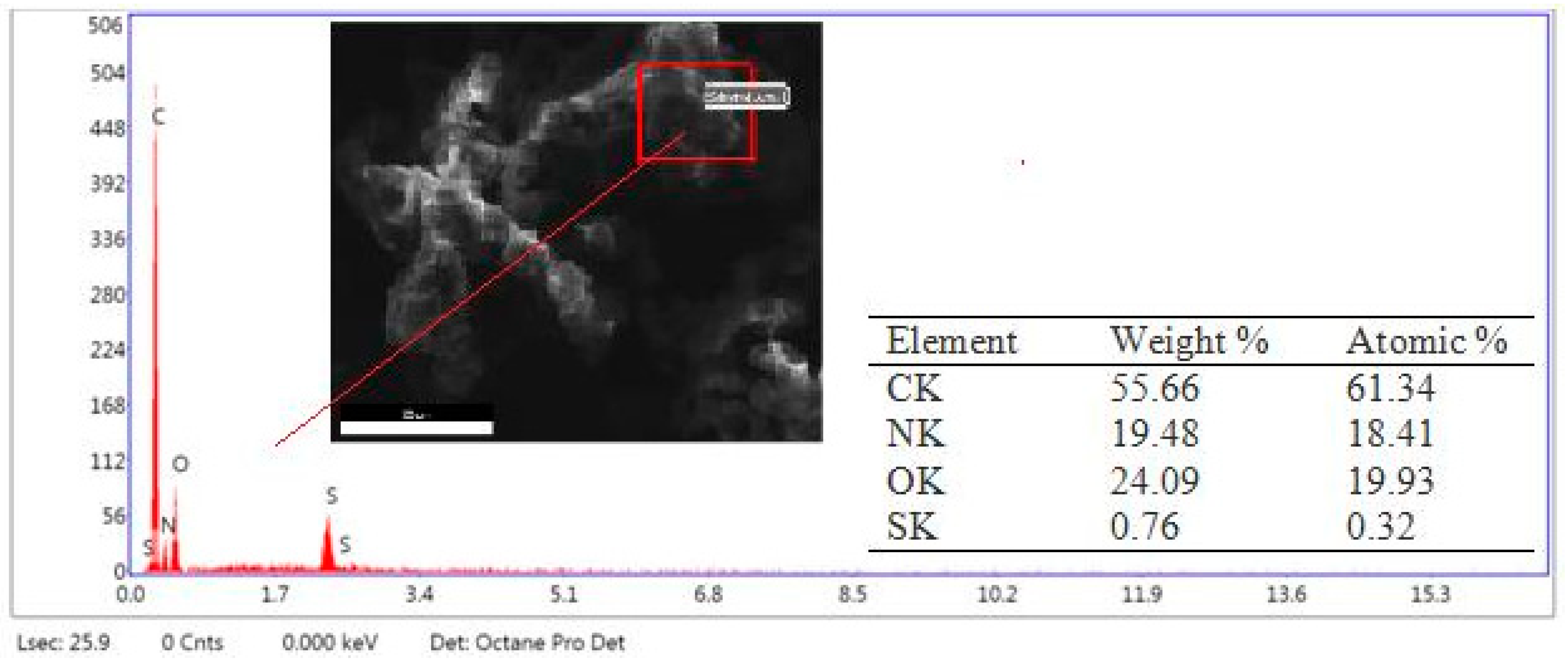
Sheep horn powder was subjected to EDS analysis to measure the wt.% of its composition and it is shown in Figure 6.
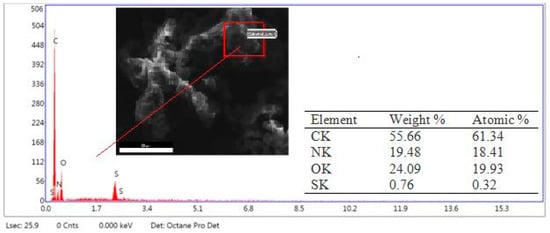
Figure 6.
EDS analysis of sheep horn powder.
3.2. Mechanical Characterisation
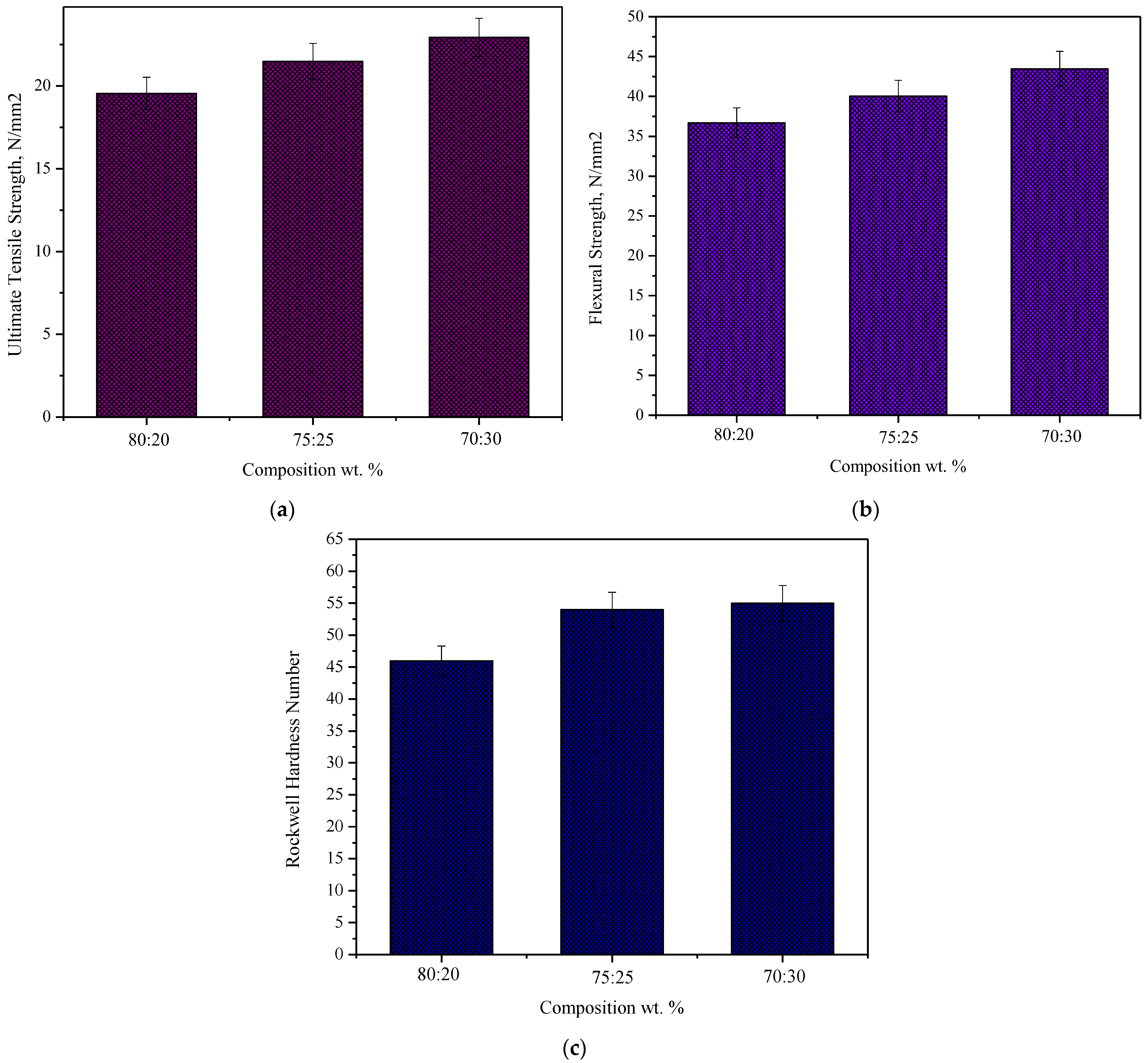
Figure 7a illustrates the tensile strength of composites reinforced with sheep horn particles at various filler loading weight percentages. This graph demonstrates how adding sheep horn particles to the produced composites significantly increases their tensile strength. The highest tensile strength was found to be attained at 30 weight percent filler content, with a measured value of 22.94 N/mm2. For a 20 weight percent filler content, a minimum value of tensile strength of 19.55 N/mm2 was noted. The strong bonding and favourable interface between the epoxy resin and the sheep horn particles were shown to be responsible for the increased tensile strength. The structure of composite materials often affects their mechanical characteristics. Therefore, these characteristics are often influenced by the component interfaces, the volume fraction occupied by inhomogeneities, and the form of the inhomogeneities. Adding more filler might weaken the composite because it promotes agglomeration, which leads to matrix fractures (initiates cracks within the matrix). The flexural strength of composites reinforced with sheep horn particles is shown in Figure 7b for various filler loading weight percentages. Similar trends have been seen in flexural strength as in tensile strength. The filler concentration of 30 weight percent produced the highest flexural strength, which was measured as 43.49 N/mm2. At 30 weight percent filler, the composite’s maximum tensile strength and flexural strength were attained. Figure 7c illustrates the Rockwell hardness for various filler loading weight percentages in composites reinforced with sheep horn particles. The hardness of sheep horn particle-reinforced composites steadily increased with the addition of horn particles. At 30% filler, the composite’s hardness was at its highest among those tested. When a substance is more resistant to deformation, its hardness rises [33,34,35]. When a matrix has more particles added, this occurs. Greater resistance to plastic deformation is offered by the filler.
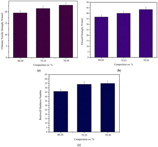
Figure 7.
Effect of filler loading on (a) tensile strength, (b) flexural strength, and (c) hardness of sheep horn particle-reinforced composites.
3.3. Thrust Force and Torque
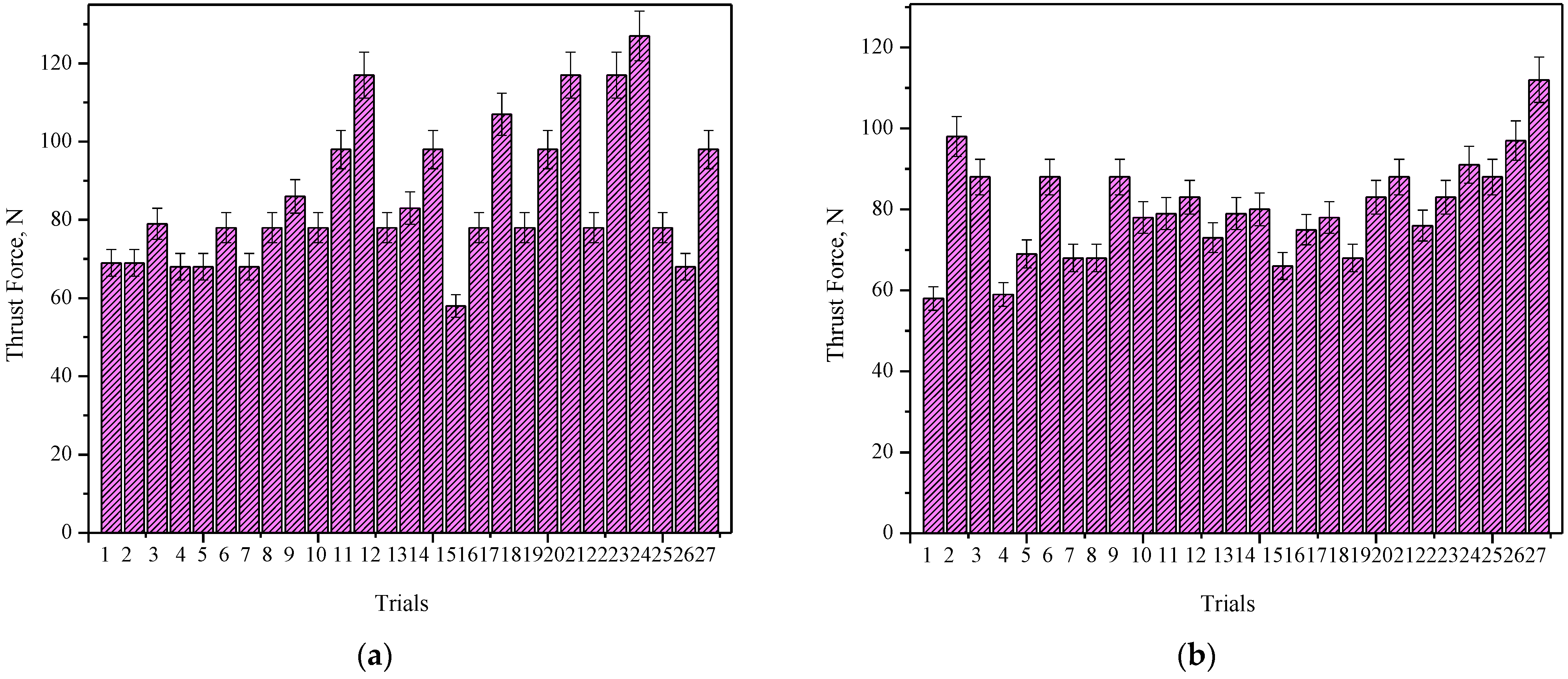
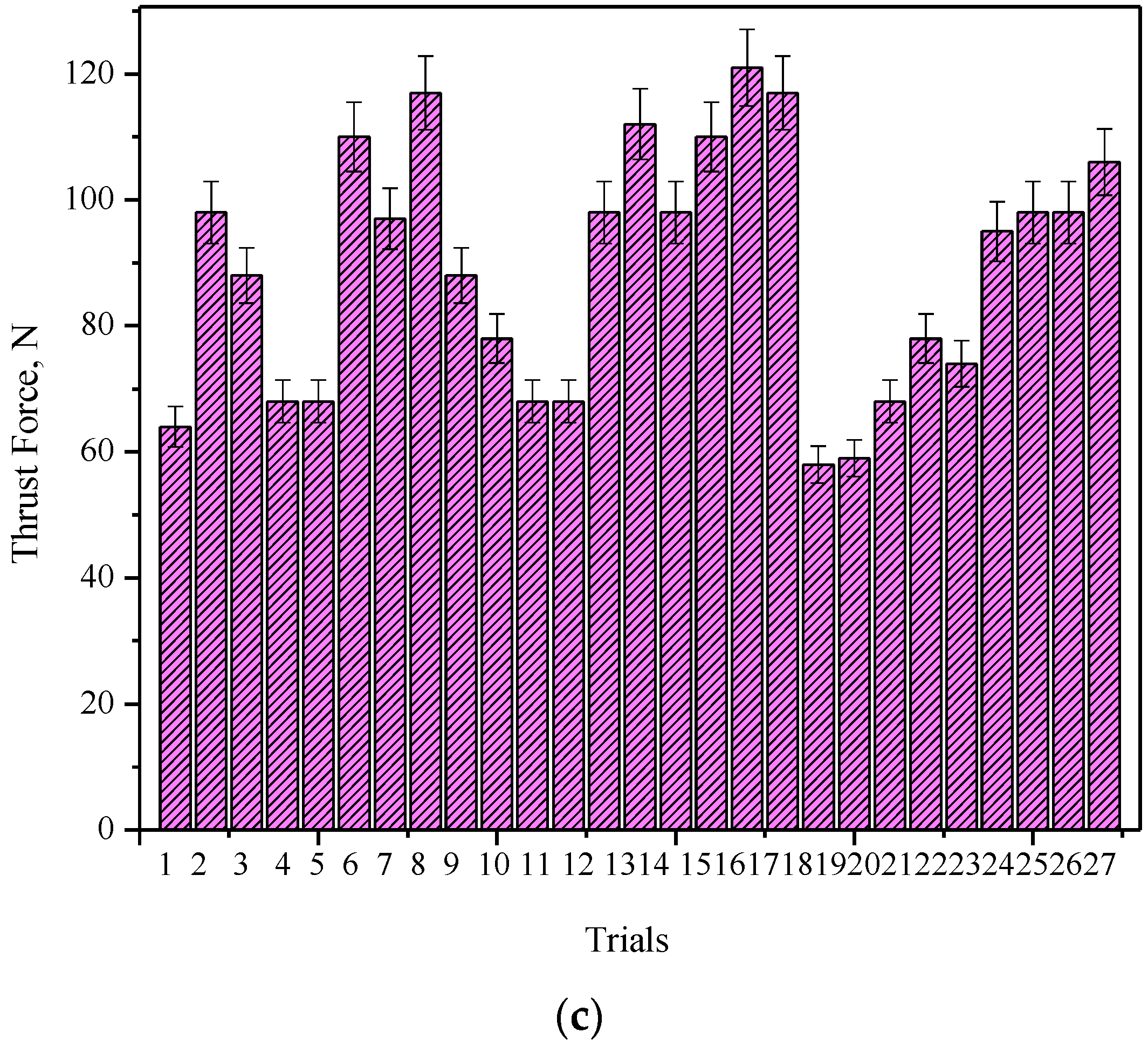
The thrust force and torque created during the drilling process (shown in Table 3) have a significant impact on the delamination’s size. Additionally, there is a critical thrust force value below which harm is prevented. The major cause of drilling-related damage is due to these cutting forces. The relationship between torque and feed rate states that the higher the feed rate, the greater the torque, which also has the potential to shorten tool life. For all feed rates, the thrust force rises as drill diameter grows, as demonstrated in Figure 8a. With an increase in feed rate in composition 2, thrust force rises. The highest thrust force was achieved with a diameter of 10 mm, a feed rate of 0.2 mm/rev, and a speed of 800 rpm. In composition 2, torque decreases as spindle speed increases [36,37,38,39]. The 10 mm diameter, 0.2 mm/rev feed rate, and speed of 400 rpm yield the most torque, as shown in Figure 8b.

Table 3.
Experimental results.
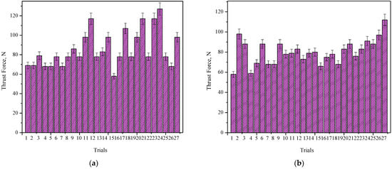
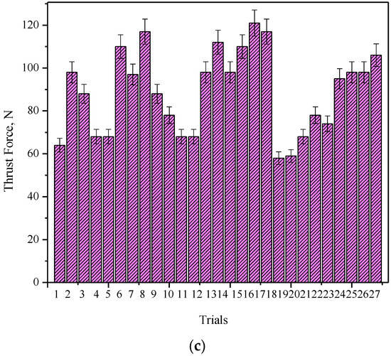
Figure 8.
Measured thrust force for input factors using dynamometer on composites. (a) Composition 70:30. (b) Composition 75:25. (c) Composition 80:20.
3.4. Response Surface Methodology
Using the response surface methodology (RSM), the effects of drilling parameters such as spindle speed, feed rate, and drill diameter on thrust force and torque were examined. Design-Expert software was used to analyse the significant factors. L27 orthogonal array planning was used for the investigations.
3.4.1. Case 1—Composition 70:30
The effects of different factors, such as spindle speed, feed, and drill diameter, on the output (thrust force and torque), were investigated using analysis of variance (ANOVA) for case 1, which is displayed in Table 4. The significance of the model was examined by contrasting it with lack of fit and simple error. Another way to do this is to monitor how close R2 is and then set R2 to unity. The model should always be able to anticipate outcomes correctly, as indicated by the significance of adequate precision (AP). If the number is greater than 4, the model is deemed to be extremely sufficient. In the current analysis, R2 and adjusted R2 for thrust force are, respectively, 0.9327 and 0.9283. For torque, the corresponding numbers are 0.8479 and 0.7973. All of these numbers are rather close to one another. The AP values of 9.8877 and 13.4919 for thrust force and torque, respectively, are both substantially greater than 4.

Table 4.
ANOVA generated for the response “Thrust Force” and “Torque”.
The surface plot makes it simpler to see the response surface. These are used to promote the required working conditions and response values. The surface plots illustrate how a thrust force and torque relate to two variables using a model equation.
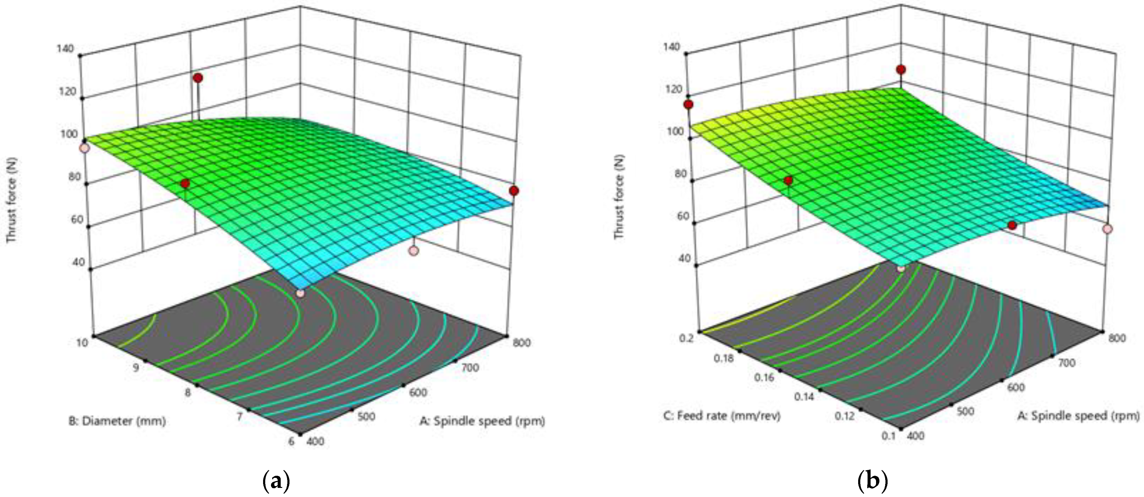
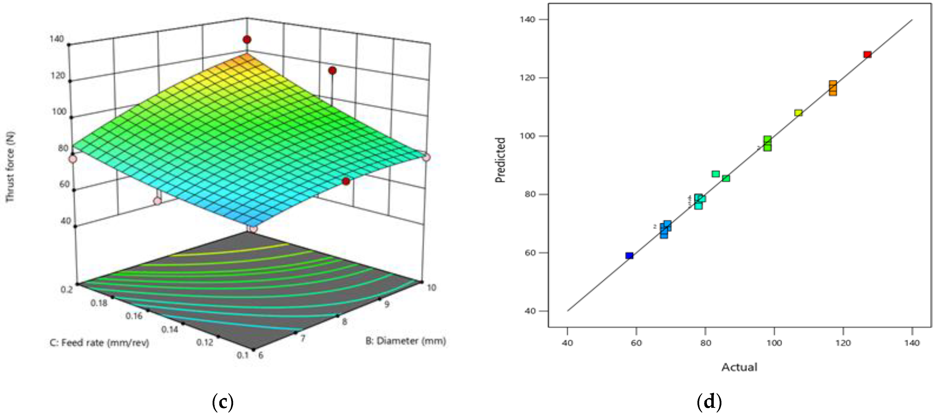
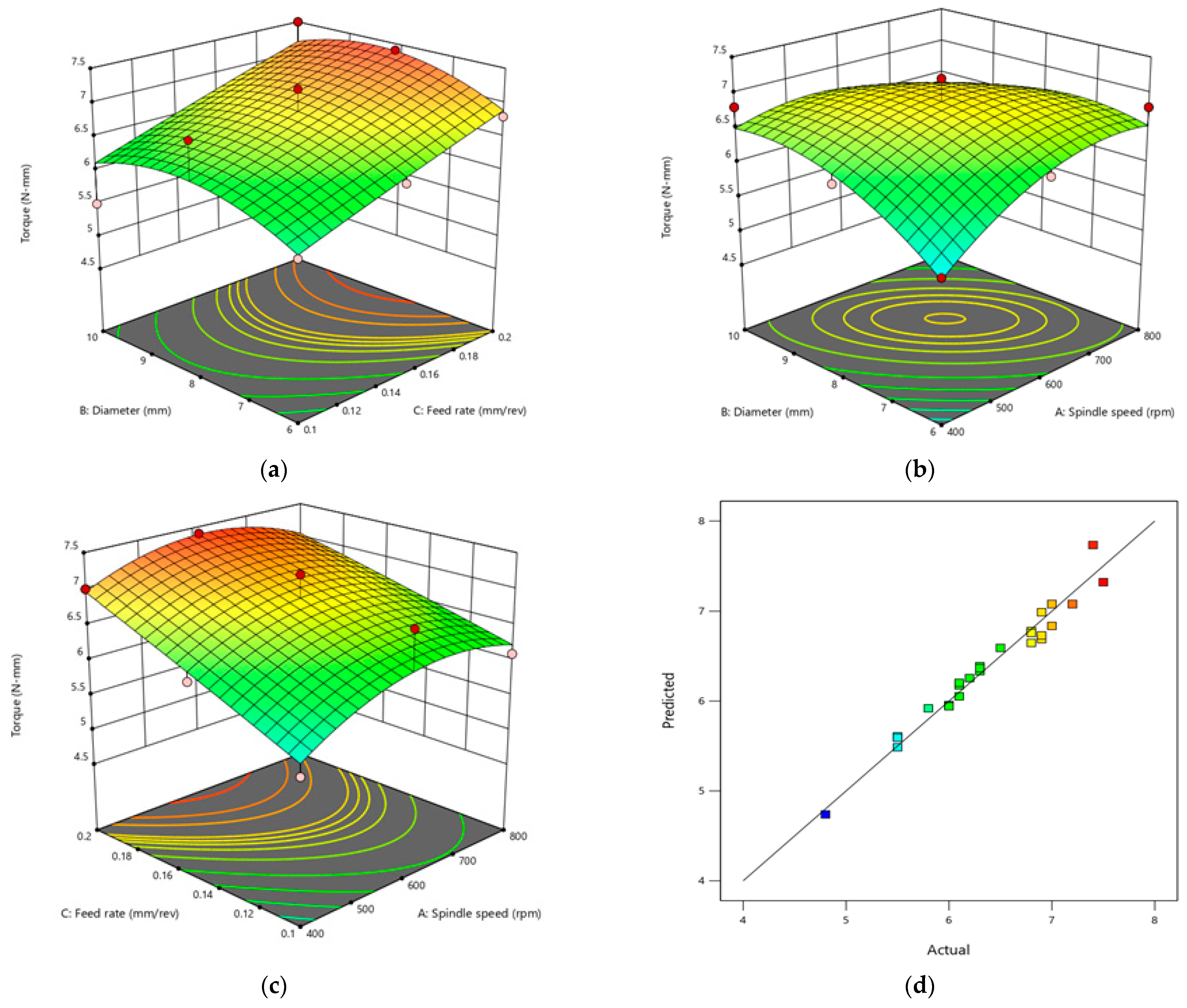
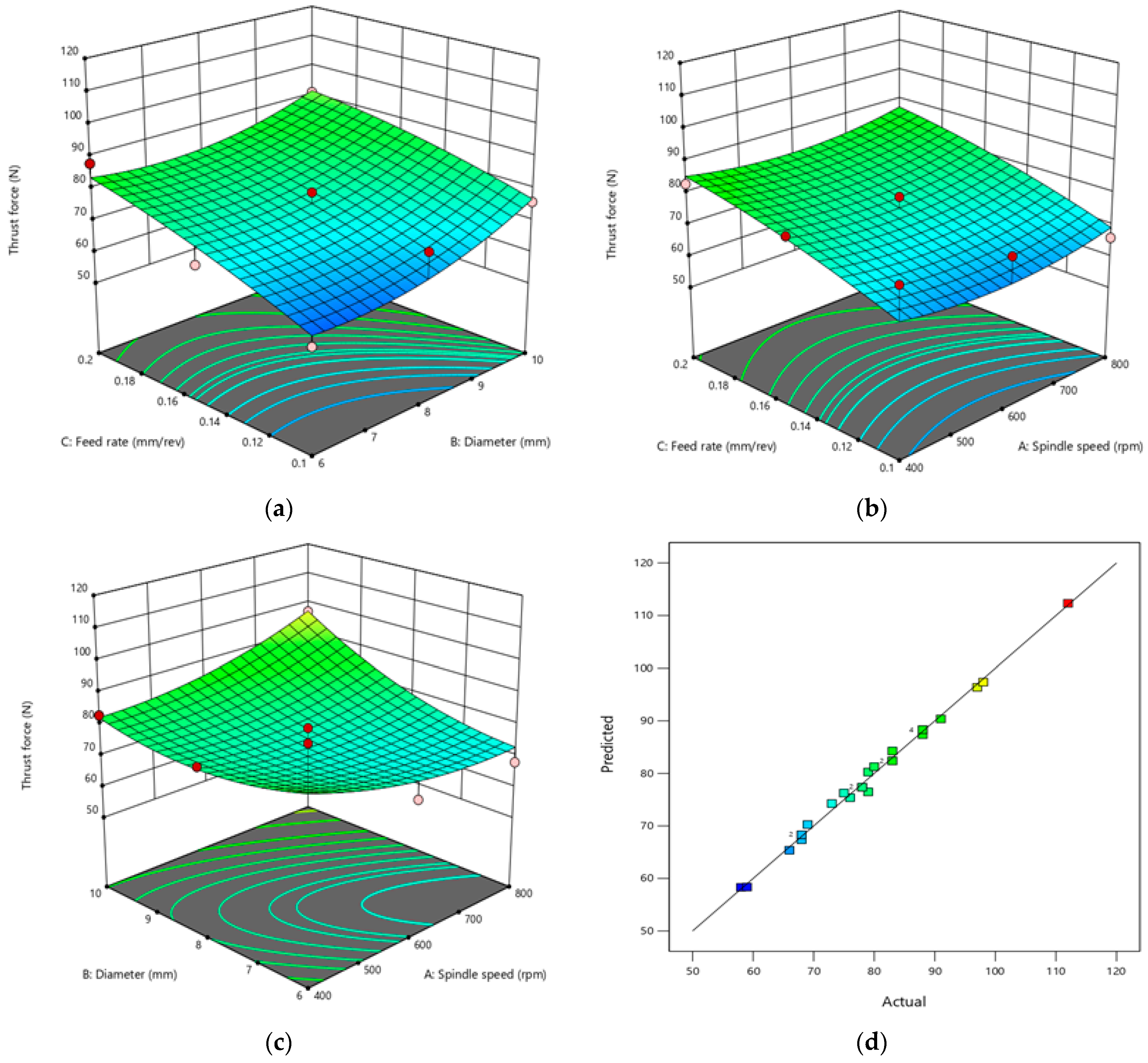
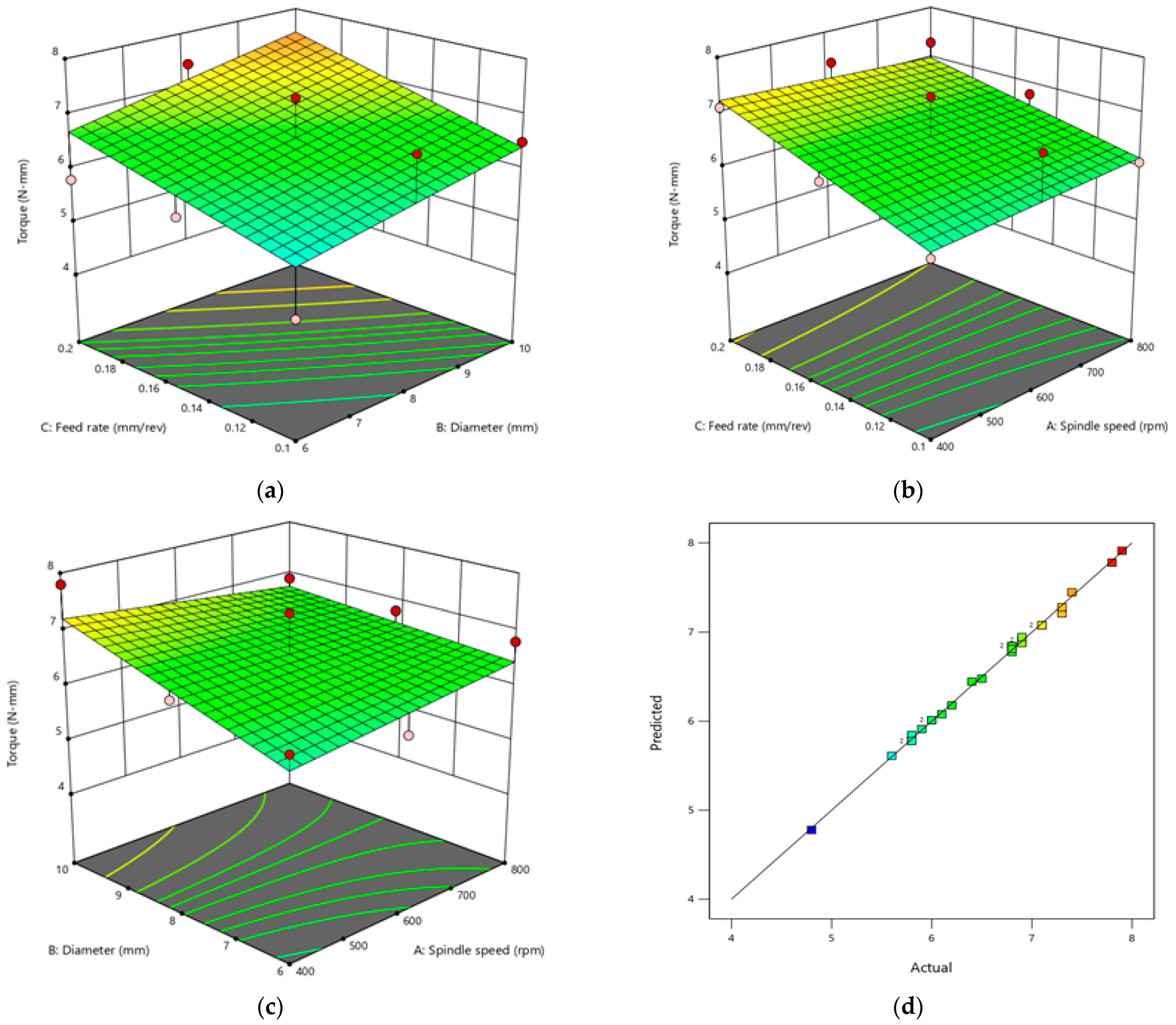
On the surface plot, which only shows two variables, the third variable is kept constant. The change in thrust force with control parameters is depicted in the 3D surface RSM graph in Figure 9. As seen in Figure 9a, the thrust force increases as the diameter and speed decrease. Similar to this, increasing feed rate while decreasing spindle speed increases thrust force (Figure 9b). While Figure 9b demonstrates that the thrust force value falls with feed rate as spindle speed rises, Figure 9c demonstrates that the thrust force value increases with feed rate and diameter. The relationship between feed and spindle speed is shown in Figure 9b,c, whereas Figure 9a shows how spindle speed and diameter interact to effect thrust force. Figure 9d compares the values of the actual and anticipated thrust forces, and it can be seen that there is good agreement [40,41,42]. The three-dimensional surface plot in Figure 10 illustrates the relationship between the factors that affect torque. It is clear that feed rate and drill diameter both have a substantial impact on torque, which also increases as drill diameter grows. Torque increases with speed until a certain point, at which point it begins to decline. As a result, the thrust force and torque are significantly influenced by the drill diameter and feed rate. Figure 10a–c show how diameter and spindle speed interact, as well as how feed rate and spindle speed interact. Figure 10a shows how feed rate and diameter impact torque. The ANOVA results show that the experimental results closely match the predicted value in Figure 10d.
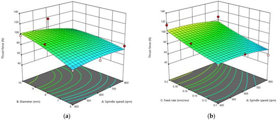
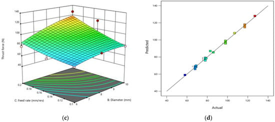
Figure 9.
The 3D surface plots of the factors that effect thrust force, including the interactions between spindle speed and diameter (a), feed rate and spindle speed (b), and feed and diameter (c). Actual vs. predicted thrust force (d).
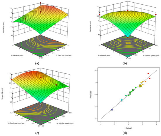
Figure 10.
The 3D surface plot of the variables controlling torque. (a) Interactions between the diameter and the feed rate, (b) diameter and the spindle speed, (c) spindle speed and feed rate. (d) Estimated vs. actual torque.
The regression models for thrust force and torque are presented in Equations (1) and (2).
Thrust force = −48.93519 + 0.197917 × N + 19.80556 × D − 486.11111 × f − 0.013333 × N × D − 0.008333 × N × f + 58.33333 × D × f − 0.000094 × N2 − 0.944444 × D2 + 1022.22222 × f2
Torque = −10.39444 + 0.021556 × N + 2.01944 × D + 18.88889 × f − 0.000938 × N × D − 0.011667 × N × f + 0.083333 × D × f − 9.58333 × 10⁻⁶ × N2 − 0.087500 × D2 − 6.66667 × f2
3.4.2. Case 2—Composition 75:25
The ANOVA for the response of thrust force is clearly displayed in Table 5, which indicates that the model is significant. The most important factors affecting thrust force are the parameters B and C. The factors listed in the table are considered significant when the value of “Prob > F” is less than 0.05. The thrust force created depends on factors such as feed rate, spindle speed, and drill diameter, as well as how these factors interact. The drill diameter and feed are more important factors on torque, and their effects are practically identical to those of thrust force, as shown in the ANOVA table. R2 and adjusted R2 for the thrust force in the current study are 0.9316 and 0.9296, respectively. The corresponding values for torque are 0.9230 and 0.9217. These values are all quite close together. The AP values for thrust force and torque, 8.9243 and 9.2094, respectively, are both significantly higher than 4.

Table 5.
ANOVA generated by the Design-Expert software for the response “Thrust Force” and “Torque”.
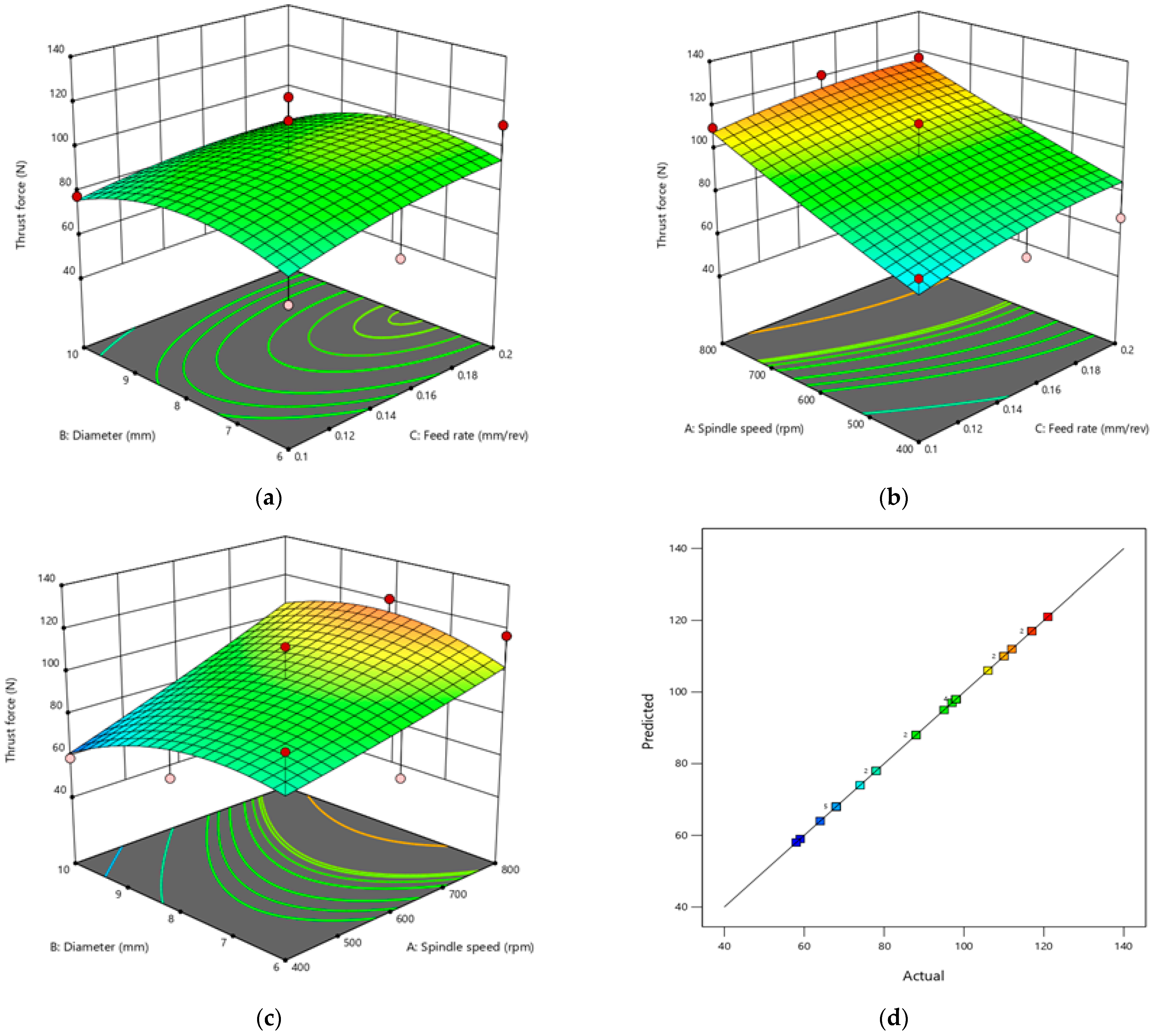
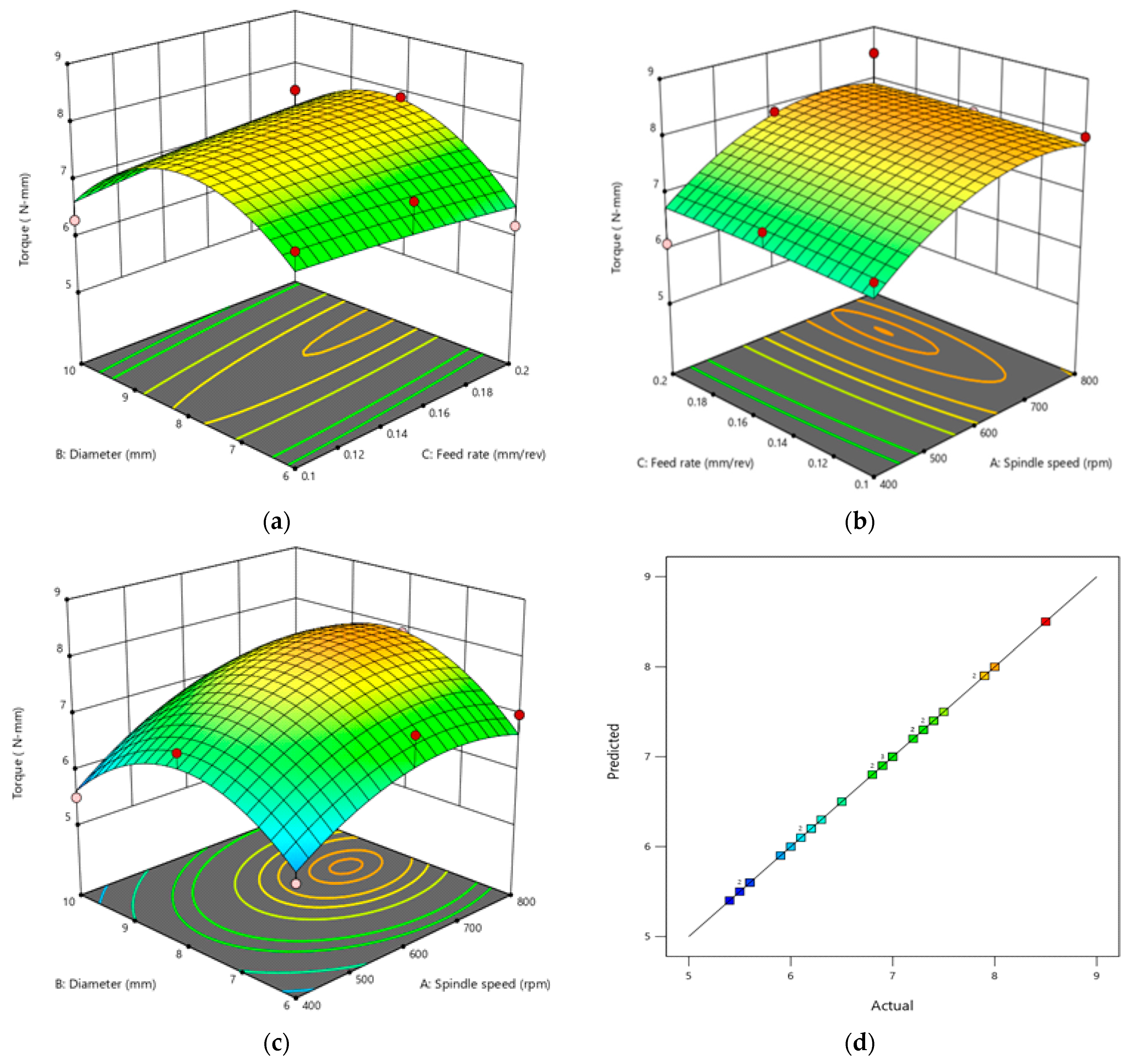
Figure 11 and Figure 12, respectively, display the 3D surface plot generated by Design-Expert software that depicts the interactions between the factors affecting thrust force and torque. Smaller diameter, lower feed rate, and lower thrust force are shown in Figure 11a, and thrust force gradually rises when these factors rise to higher levels. Similarly, Figure 11b illustrates higher feed rate, lower spindle speed, and larger thrust force. The relationship between diameter and spindle speed is seen in Figure 11c; the higher the spindle speed and diameter, the greater the thrust force value. Figure 11a depicts how feed and diameter interact to create thrust force, Figure 11b depicts how feed and spindle speed interact, and Figure 11c depicts how speed and diameter interact. Actual and predicted thrust force values are shown in Figure 11d, and it was noticed that there was good agreement. The three-dimensional surface plot in Figure 12 depicts the interplay of factors that impact torque while only taking into account two variables and holding the third variable constant. It is evident that drill diameter and feed rate have the most effect on torque, whereas speed has the smallest effect of all the components. Torque also rises as drill diameter and feed rate increase. Therefore, feed rate and drill diameter have considerable impact on the torque. Figure 12a illustrates how feed rate and diameter affect torque, Figure 12b illustrates how diameter and spindle speed interact, and Figure 12c illustrates how feed rate and spindle speed interact. The experimental findings are in good agreement with the expected value, as shown in Figure 12d, according to the ANOVA results.
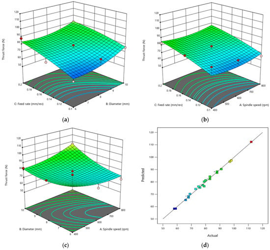
Figure 11.
The 3D surface maps. (a) The interaction between feed rate and diameter on thrust force. (b) The interaction between feed and spindle speed. (c) The interaction between spindle speed and diameter. (d) Actual vs. predicted thrust force.
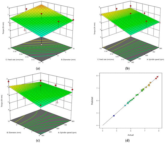
Figure 12.
(a) The interaction between feed rate and diameter. (b) The interaction between feed and spindle speed. (c) Spindle speed and diameter interaction. (d) Actual vs. predicted torque.
The regression models for thrust force and torque are presented in Equations (3) and (4).
Thrust force = +177.45370 − 0.238194 × N − 23.97222 × D + 521.66667 × f + 0.016250 × N × D + 0.008333 × N × f − 16.66667 × D × f + 0.000093 × N2+1.22222 × D2 − 711.11111 × f2
Torque = −6.22500 + 0.002764 × N + 1.77639 × D + 47.50000 × f − 0.000604 × N × D − 0.012500 × N × f + 0.333333 × D × f + 3.33333×10⁻⁶ × N2 − 0.079167 × D2 − 106.66667 × f2
3.4.3. Case 3—Composition 80:20
The model is significant, as shown by the ANOVA for the response of thrust force in Table 6 which is clearly presented. The parameters A and C are crucial in determining thrust force. As spindle speed and feed rate increase, so does the torque. When “Prob > F” is less than 0.05, the factors stated in the Table 6 are deemed significant. Various variables, including feed rate, spindle speed, drill diameter, and their interactions, affect the thrust force produced. The ANOVA table demonstrates that the drill diameter and feed are more significant variables and that their effects on torque are almost equal to those of thrust force. In the present analysis, R2 and corrected R2 for thrust force are 0.9296 and 0.9362, respectively. For torque, the corresponding values are 0.8266 and 0.7949. All of these numbers are rather close to one another. The AP values for thrust force and torque, 7.4983 and 9.9349, respectively, are also noticeably more than 4.

Table 6.
ANOVA generated by the Design-Expert software for the response “Thrust Force” and “Torque”.
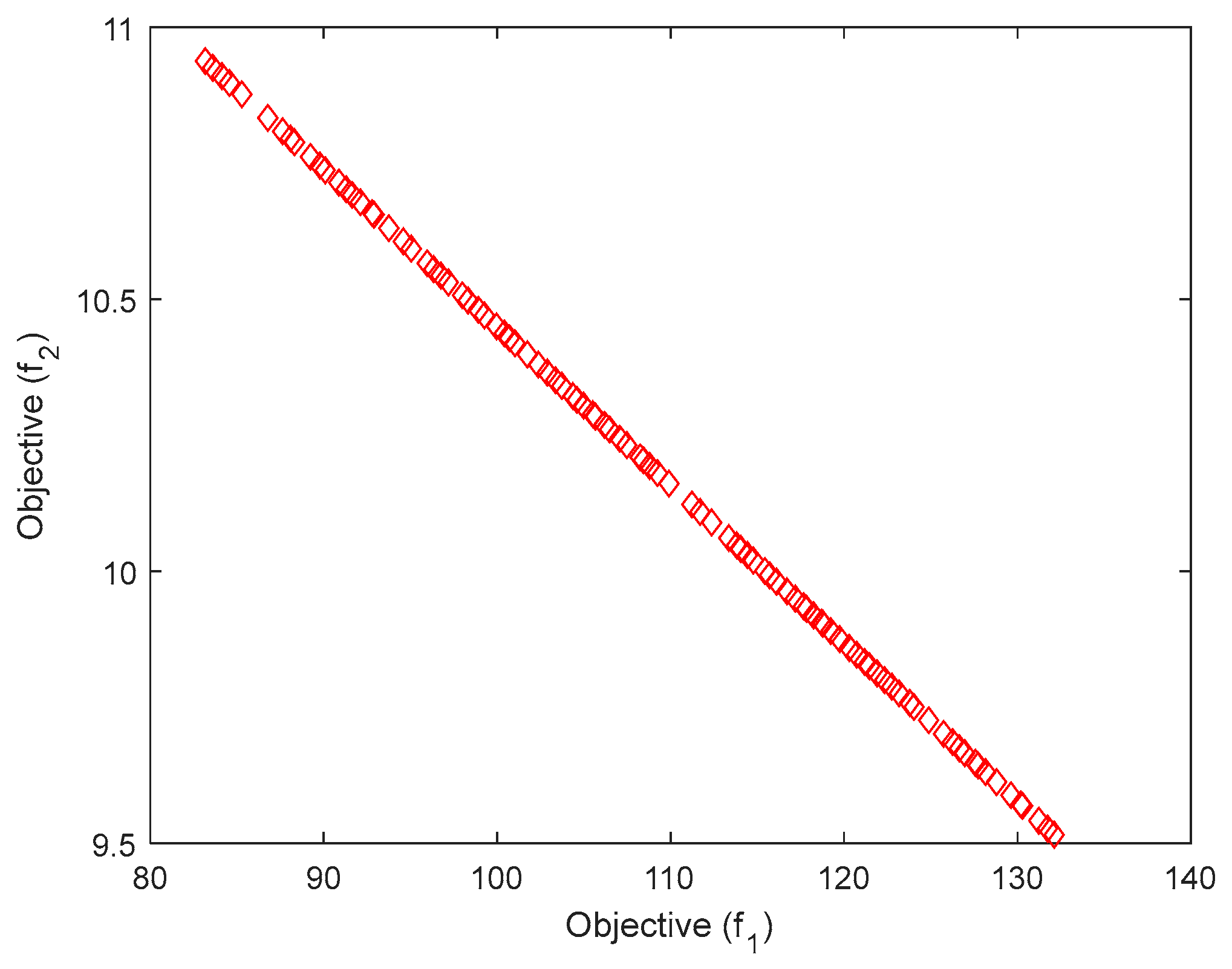
Figure 13 and Figure 14 show the 3D surface plots for thrust force and torque, respectively, along with the interactions between the factors affecting each. Results show that for this composite drilling, spindle speed and feed rate have a far greater impact on responses than drill diameter. As demonstrated in Figure 13, higher levels of speed and feed rate result in greater thrust force (a and b). Thrust force first rises with diameter up to 8 mm then decreases as diameter increases (Figure 13c). Figure 13a depicts how feed and diameter interact to create thrust force, Figure 13b depicts how feed and spindle speed interact, and Figure 13c depicts how speed and diameter interact. ANOVA demonstrates that the experiment’s results closely match the values expected, as seen in Figure 13d. The three-dimensional surface plot in Figure 14 depicts the interplay of factors that impact torque while only taking into account two variables and holding the third variable constant. It is evident that spindle speed and feed rate have the highest effects on torque, which increase with increasing drill diameter up to 8 mm, then decrease at 10 mm. Therefore, in case 3, spindle speed and feed rate have a greater impact on torque than drill diameter. Figure 14a illustrates how feed rate and diameter effect torque, Figure 14b illustrates how feed and spindle speed interact, and Figure 14c illustrates how spindle speed and diameter interact. As seen in Figure 14d, the results of the experiment and the predicted value are in strong agreement. Figure 15 shows a Pareto chart for multiobjective optimisation, considering the output objectives such as thrust force and torque.
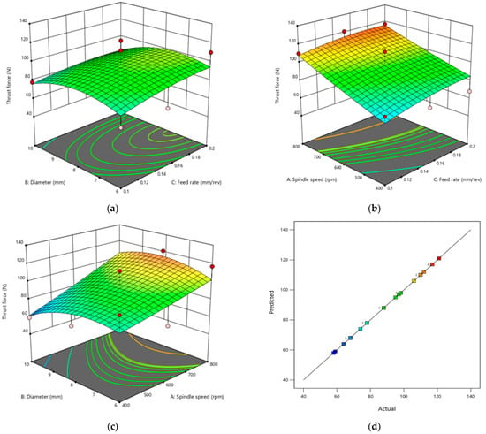
Figure 13.
(a) The interaction between feed rate and diameter with thrust force, whereas (b) shows the interaction between feed and spindle speed, and (c) shows the interaction between spindle speed and diameter. (d) Actual vs. predicted thrust force.
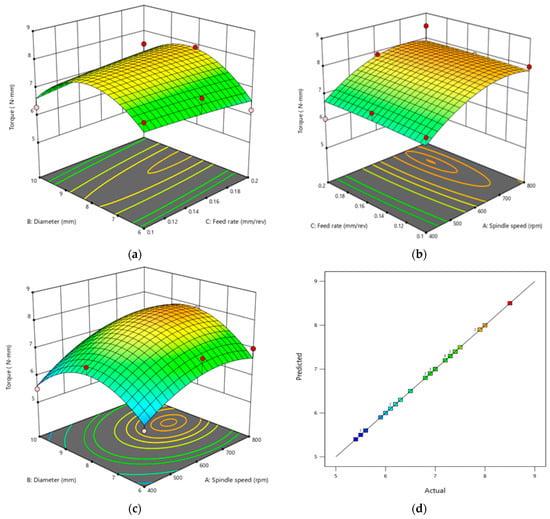
Figure 14.
The 3D surface maps of the variables controlling torque. (a) Diameter and feed rate interaction. (b) Feed rate and spindle speed interaction. (c) Spindle speed and diameter interaction. (d) Actual vs. predicted torque.
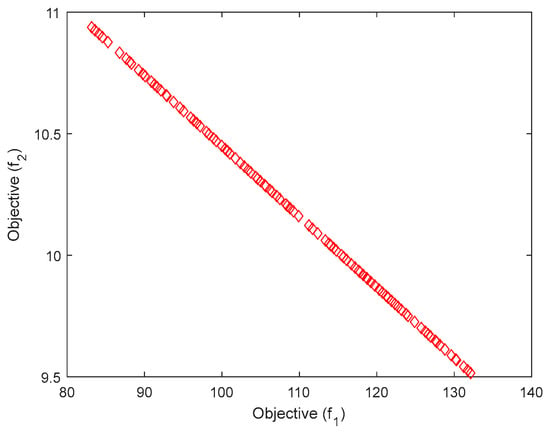
Figure 15.
Pareto chart for multiobjective optimisation. Objective (f1) = thrust force, objective (f2) = torque.
The regression models for thrust force and torque are presented in Equations (5) and (6).
Thrust force = −111.55556 − 0.031667 × N + 34.84722 × D + 696.11111 × f + 0.013542 × N × D − 0.150000 × N × f − 18.33333 × D × f + 0.000025 × N2 − 2.62500 × D2 − 1166.66667 × f2
Torque = −11.58563 + 0.015976 × N + 3.58895 × D − 10.90266 × f + 0.000410 × N × D − 0.001393 × N × f + 2.13907 × D × f − 0.000013 × N2 − 0.257183 × D2 − 15.14567 × f2
3.5. Hole Quality
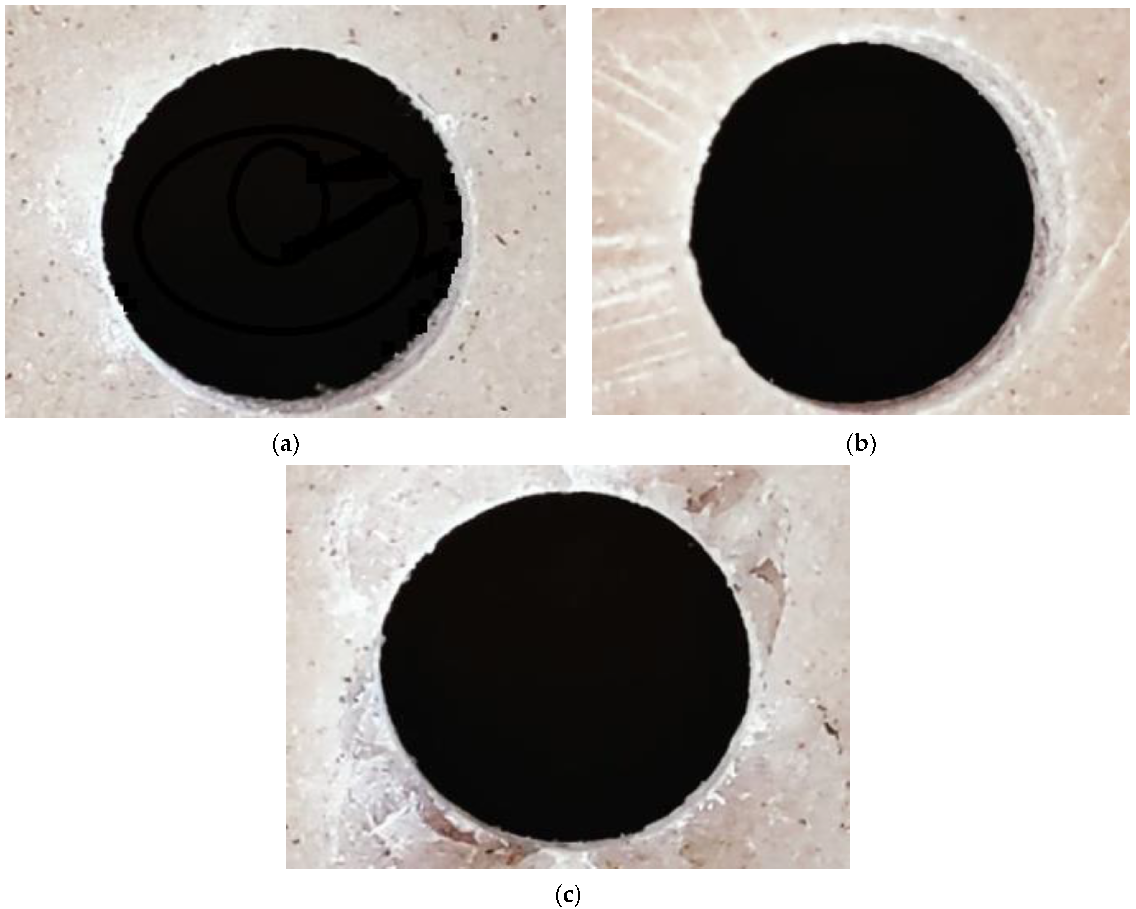
Any drilling procedure’s purpose is to ensure that the produced holes are of an acceptable quality. As a consequence, the measurement of cutting forces was carried out concurrently with an assessment of the finish quality that included an investigation of damage to the composites caused by drilling. In most cases, lowering the cutting pressures reduces machining-related damage. Such damage for drill holes was examined using light microscopy; the results are shown in Figure 16. Images acquired at both the entrance and exit surfaces showed that the burr formation was reduced in the 6 mm diameter hole, irrespective of the composition of the composites. The findings indicate that larger diameter and greater feed rate caused more exit-hole damage with more perturbations in pushouts at the surface. Laminate pushouts at the exit side were seen at larger drill diameters compared to smaller ones. Thus, the ply suffered substantially less visible damage with smaller drill diameters. With regard to hole diameter, 0.1 mm/rev and 0.15 mm/rev feed rates produce the good results. As a result of our research, a feed rate of 0.1 mm/rev produced favourable results for hole diameter and circularity.
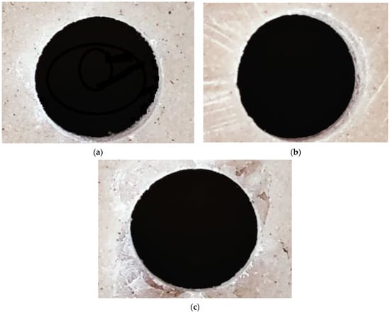
Figure 16.
Hole quality assessment using light microscopy. (a) A 6 mm diameter drill, (b) 8 mm diameter drill, (c) 10 mm diameter drill.
4. Conclusions
In the present study, sheep horn particle-reinforced polymer composites have been fabricated considering different matrix to reinforcement ratios, and the mechanical properties have been investigated and the composites subjected to drilling on the basis of central composite design for optimising drilling process parameters. As output responses, the thrust force and torque have been measured. It should be noted that a variety of control factors have an impact on the composite’s tensile and flexural strength values. Many factors need to be under control, even when drilling composite materials. Here, we spoke about how these parameters affect the output responses in light of the experimental findings and the ANOVA analysis. The study presented above leads to the following conclusions:
- (1)
- Increases in filler weight lead to increases in tensile strength, flexural strength, and hardness; 30 weight percent reinforcement was determined to be the optimal proportion.
- (2)
- The study shows that the drill diameter and feed rate, which have a higher percentage impact on the characteristics of composites than spindle speed, are the two main cutting factors impacting thrust force. With an increase in feed rate and diameter, the thrust force rises.
- (3)
- The 10 mm drill, when compared to other drills, has the highest drilling thrust force within the range of drill diameters considered.
- (4)
- For drilling sheep horn filler laminates, the combination of 6 mm diameter, 0.1 mm/rev feed rate, and 400 rpm speed would be the combination for best practice within the chosen drilling range.
- (5)
- As the thrust force experienced increases with increasing hole diameter, indicating that the thrust force has a greater impact on the hole surface, the surface quality of the 6 mm diameter hole was better than the 10 mm diameter hole surface.
The results of the ANOVA show that the experimental data and the predicted values correspond quite well, with an acceptable level of error being less than 10%. The issues of rejection in components with holes will be solved by this form of testing. This will therefore be helpful for industrial component applications.
Author Contributions
Conceptualization, C.A. and M.Y.J.; methodology, C.A.; validation, A.N.A., C.A. and M.A. (Mohamed Abbas); formal analysis, A.N.A.; investigation, C.A. and M.Y.J.; resources, A.A.A.; data curation, A.N.A.; writing—original draft preparation, C.A.; writing—review and editing, A.A.A.; visualization, M.A. (Mamdooh Alwetaishi); supervision, C.A.; project administration, O.S.A.; funding acquisition, O.S.A. All authors have read and agreed to the published version of the manuscript.
Funding
This research is supported by the Structures and Materials (S&M) Research Lab of Prince Sultan University and the authors acknowledge the support of Prince Sultan University for paying the article processing charges (APC) of this publication.
Institutional Review Board Statement
Not applicable.
Informed Consent Statement
Not applicable.
Data Availability Statement
All data used to support the findings of this study are included within the article.
Acknowledgments
The authors extend their appreciation to the Deanship of Scientific Research at King Khalid University (KKU) for funding this research through the Research Group Program under the Grant Number: R.G.P. 1/256/43. The authors would like to acknowledge the support received by Taif University Researchers Supporting Project Number TURSP-2020/240, Taif University, Taif, Saudi Arabia.
Conflicts of Interest
The authors declare no conflict of interest.
References
- Archana, D.P.; Reddy, H.N.J.; Prabhakara, R.; Aswath, M.U.; Chandrashekar, A. Processing and Properties of Biodegradable Composites to Strengthen Structures. J. Inst. Eng. (India) Ser. C 2022, 103, 39–52. [Google Scholar] [CrossRef]
- Subramanya, R.; Satyanarayana, K.G.; Pilar, B.S. Evaluation of structural, tensile and thermal properties of banana fibers. J. Nat. Fibers 2017, 14, 485–497. [Google Scholar]
- Mohankumararadhya, H.M.; Wadappi, P.; Chandrashekar, A.; Naik, Y. Studies on bio waste product particle reinforced polymer composites. AIP Conf. Proc. 2020, 2274, 030047. [Google Scholar]
- Mohanavel, V.; Raja, T.; Yadav, A.; Ravichandran, M.; Winczek, J. Evaluation of mechanical and thermal properties of jute and ramie reinforced epoxy-based hybrid composites. J. Nat. Fibers 2021, 19, 1–11. [Google Scholar] [CrossRef]
- Archana, D.P.; Reddy, H.N.J. Potential of Natural Fibres for Strengthening Existing Structures—A Review. Int. J. Struct. Eng. Anal. 2018, 4, 38–46. [Google Scholar]
- Bharath, K.N.; Basavarajappa, S. Applications of biocomposite materials based on natural fibers from renewable resources: A review. Sci. Eng. Compos. Mater. 2016, 23, 123–133. [Google Scholar] [CrossRef]
- McGregor, B.A. Physical, chemical, and tensile properties of cashmere, mohair, alpaca, and other rare animal fibers. In Handbook of Properties of Textile and Technical Fibres, 2nd ed.; Woodhead Publishing: Sawston, UK, 2018; pp. 105–136. [Google Scholar]
- Baptista, C.; Martins, G.; Santos, C.; Mateus, A.; Antunes, F. Microstructure of Thermoplastic Composites Reinforced with Wool and Wood. Appl. Mech. Mater. 2019, 890, 98–112. [Google Scholar] [CrossRef]
- Kumar, D.; Bhoopathy, S.R. Mechanical and thermal properties of horn fibre reinforced polypropylene composites. Procedia Eng. 2014, 97, 648–659. [Google Scholar] [CrossRef]
- Mysore, T.H.M.; Patil, A.Y.; Raju, G.U.; Banapurmath, N.R.; Bhovi, P.M.; Afzal, A.; Alamri, S.; Saleel, C.A. Investigation of mechanical and physical properties of big sheep horn as an alternative biomaterial for structural applications. Materials 2021, 14, 4039. [Google Scholar] [CrossRef]
- Trim, M.W.; Horstemeye, M.F. The effects of water and microstructure on the mechanical properties of Bighorn Sheep (Ovis canadesis) horn keratin. Acta Biomater. 2011, 7, 1228–1240. [Google Scholar] [CrossRef]
- Johnson, K.L.; Trim, M.W.; Francis, D.K.; Whittington, W.R.; Miller, J.A.; Bennett, C.E.; Horstemeyer, M.F. Moisture, Anisotropy, Stress State, and Strain Rate Effects on Bighorn Sheep Horn Keratin Mechanical Properties. Acta Biomater. 2017, 48, 300–308. [Google Scholar] [CrossRef]
- Ambali, I.O.; Shuaib-Babata, Y.L.; Lalasi, T.O.; Laremu, I.N.; Ibrahim, H.K.; Elakhame, Z.U.; Abdulraman, S.O. Suitability Horn as Filler in an Epoxy Composite of Cow. J. Appl. Sci. Environ. Manag. 2019, 23, 475–482. [Google Scholar] [CrossRef]
- Savannanavar, R.N.; Toli, K.; Manakur, J.; Chandra, J.K. Experimental study on mechanical properties and electronic conductivity of natural fibre reinforcement. Int. J. Adv. Res. Innov. Ideas Educ. 2017, 2, 13–19. [Google Scholar]
- Kehinde, O.; Omotosho, O.A.; Ohijeagbon, I.O. Impact of varying Laterite and Cow horn additives on the mechanical properties of Cement matrix plastic tiles. J. Phys. Conf. Ser. 2019, 1378, 022078. [Google Scholar] [CrossRef]
- Cemal, K. Mechanical properties of waste mussel shell particles reinforced epoxy composites. Mater. Test. 2019, 61, 149–154. [Google Scholar]
- Acda, M.N. Waste Chicken Feather as Reinforcement in Cement-Bonded Composites. Philipp. J. Sci. 2014, 139, 161–166. [Google Scholar]
- Nassar, M.M.A.; Arunachalam, R.; Alzebdeh, K.I. Machinability of natural fiber reinforced composites: A review. Int. J. Adv. Manuf. Technol. 2017, 88, 2985–3004. [Google Scholar] [CrossRef]
- McKittrick, J.; Chen, P.Y.; Bodde, S.G.; Yang, W.; Novitskaya, E.E.; Meyers, M.A. The Structure, Functions, and Mechanical Properties of Keratin. J. Miner. Metals Mater. Soc. 2012, 64, 449–468. [Google Scholar] [CrossRef]
- Tombolato, L.; Novitskaya, E.E.; Chen, P.; Sheppard, F.A.; McKittrick, J. Microstructure, elastic properties and deformation mechanisms of horn keratin. Acta Biomater. 2010, 6, 319–330. [Google Scholar] [CrossRef]
- Wang, D.; Onawumi, P.Y.; Ismail, S.O.; Dhakal, H.N.; Popov, I.; Schmidt, V.V.S.; Roy, A. Machinability of natural-fibre-reinforced polymer composites: Conventional vs. ultrasonically-assisted machining. Compos. Part A Appl. Sci. Manuf. 2019, 119, 188–195. [Google Scholar] [CrossRef]
- Babu, J.; Alex, N.P.; Mohan, K.P.; Philip, J.; Davim, J.P. Examination and modification of equivalent delamination factor for assessment of high speed drilling. J. Mech. Sci. Technol. 2016, 30, 5159–5165. [Google Scholar] [CrossRef]
- Vinayagamoorthy, R.; Manoj, I.V.; Kumar, G.N.; Chand, I.S.; Kumar, G.V.S.C.; Kumar, K.S. A central composite design based fuzzy logic for optimization of drilling parameters on natural fiber reinforced composite. J. Mech. Sci. Technol. 2018, 32, 2011–2020. [Google Scholar] [CrossRef]
- Devi, G.R.; Palanikumar, K. Evaluation of Thrust force in Drilling Woven roving Glass fibre reinforced Aluminium Sandwich laminates with TiAlN coated drill using Taguchi analysis, Frontiers in Automobile and Mechanical Engineering. IOP Conf. Ser. Mater. Sci. Eng. 2017, 197, 012055. [Google Scholar] [CrossRef]
- Vijayan, D.; Abhishek, P.; Kumar, Y.G.M.; Balaji, P.; Reddy, P.S.K. Optimization of Drilling Parameters of Carbon Fiber Composites using RSM based Desirability Function. IOP Conf. Ser. Mater. Sci. Eng. 2018, 390, 012076. [Google Scholar] [CrossRef]
- Bharath, K.N.; Manjunatha, G.B.; Santhosh, K. Failure analysis and the optimal toughness design of sheep-wool reinforced epoxy composites. Fail. Anal. Biocompos. Fibre Reinf. Compos. Hybrid Compos. 2019, 97–107. [Google Scholar]
- Heidari, M.; Vosoughi, M.; Sadeghi, H.; Dargahi, A.; Mokhtari, S.A. Degradation of diazinon from aqueous solutions by electro-Fenton process: Effect of operating parameters, intermediate identification, degradation pathway, and optimization using response surface methodology (RSM). Sep. Sci. Technol. 2021, 56, 2287–2299. [Google Scholar] [CrossRef]
- Dargahi, A.; Vosoughi, M.; Mokhtari, S.A.; Vaziri, Y.; Alighadri, M. Electrochemical degradation of 2,4-Dinitrotoluene (DNT) from aqueous solutions using three-dimensional electrocatalytic reactor (3DER): Degradation pathway, evaluation of toxicity and optimization using RSM-CCD. Arab. J. Chem. 2022, 15, 103648. [Google Scholar] [CrossRef]
- Mahmoudi, M.M.; Khaghani, R.; Dargahi, A.; Tehrani, G.M. Electrochemical degradation of diazinon from aqueous media using graphite anode: Effect of parameters, mineralisation, reaction kinetic, degradation pathway and optimisation using central composite design. Int. J. Environ. Anal. Chem. 2022, 102, 1709–1734. [Google Scholar] [CrossRef]
- Vigneshwaran, S.; John, K.M.; Johnson, R.D.J.; Uthayakumar, M.; Arumugaprabu, V.; Kumaran, S.T. Conventional and unconventional machining performance of natural fibre-reinforced polymer composites: A review. J. Reinf. Plast. Compos. 2021, 40, 553–567. [Google Scholar] [CrossRef]
- Archana, D.P.; Reddy, H.N.J.; Paruti, B. Mechanical Characterization of Biocomposites Reinforced with Untreated and 4% NaOH-Treated Sisal and Jute Fibres. Appl. Mater. Agric. Eng. 2022, 2022, 7777904. [Google Scholar] [CrossRef]
- Aftab, H.; Rahman, G.S.; Kamruzzaman, M.; Khan, M.A.; Ali, M.F.; Al Mamun, M.A. Physico-mechanical properties of industrial tea waste reinforced jute unsaturated polyester composites. J. Eng. Adv. 2022, 3, 42–49. [Google Scholar] [CrossRef]
- Pinto, R.; Afzal, A.; D’Souza, L.; Ansari, Z.; Mohammed Samee, A.D. Computational Fluid Dynamics in Turbomachinery: A Review of State of the Art. Arch. Comput. Methods Eng. 2017, 24, 467–479. [Google Scholar] [CrossRef]
- Afzal, A.; Ansari, Z.; Faizabadi, A.; Ramis, M. Parallelization Strategies for Computational Fluid Dynamics Software: State of the Art Review. Arch. Comput. Methods Eng. 2017, 24, 337–363. [Google Scholar] [CrossRef]
- Afzal, A.; Aabid, A.; Khan, A.; Afghan, S.; Rajak, U.; Nath, T.; Kumar, R. Response Surface Analysis, Clustering, and Random Forest Regression of Pressure in Suddenly Expanded High-Speed Aerodynamic Flows. Aerosp. Sci. Technol. 2020, 107, 106318. [Google Scholar] [CrossRef]
- Afzal, A.; Nawfal, I.; Mahbubul, I.M.; Kumbar, S.S. An Overview on the Effect of Ultrasonication Duration on Different Properties of Nanofluids. J. Therm. Anal. Calorim. 2019, 135, 393–418. [Google Scholar] [CrossRef]
- Afzal, A.; Abdul Mujeebu, M. Thermo-Mechanical and Structural Performances of Automobile Disc Brakes: A Review of Numerical and Experimental Studies. Arch. Comput. Methods Eng. 2019, 26, 1489–1513. [Google Scholar] [CrossRef]
- Jilte, R.; Afzal, A.; Panchal, S. A Novel Battery Thermal Management System Using Nano-Enhanced Phase Change Materials. Energy 2021, 219, 119564. [Google Scholar] [CrossRef]
- Afzal, A.; Khan, S.A.; Salee, C.A. Role of Ultrasonication Duration and Surfactant on Characteristics of ZnO and CuO Nanofluids. Mater. Res. Express 2019, 6, 1150d8. [Google Scholar] [CrossRef]
- Samylingam, L.; Aslfattahi, N.; Saidur, R.; Mohd, S.; Afzal, A. Solar Energy Materials and Solar Cells Thermal and Energy Performance Improvement of Hybrid PV/T System by Using Olein Palm Oil with MXene as a New Class of Heat Transfer Fluid. Sol. Energy Mater. Sol. Cells 2020, 218, 110754. [Google Scholar] [CrossRef]
- Afzal, A.; Alshahrani, S.; Alrobaian, A.; Buradi, A.; Khan, S.A. Power Plant Energy Predictions Based on Thermal Factors Using Ridge and Support Vector Regressor Algorithms. Energies 2021, 14, 7254. [Google Scholar] [CrossRef]
- Said, Z.; Sharma, P.; Syam Sundar, L.; Afzal, A.; Li, C. Synthesis, Stability, Thermophysical Properties and AI Approach for Predictive Modelling of Fe3O4 Coated MWCNT Hybrid Nanofluids. J. Mol. Liq. 2021, 340, 117291. [Google Scholar] [CrossRef]
Publisher’s Note: MDPI stays neutral with regard to jurisdictional claims in published maps and institutional affiliations. |
© 2022 by the authors. Licensee MDPI, Basel, Switzerland. This article is an open access article distributed under the terms and conditions of the Creative Commons Attribution (CC BY) license (https://creativecommons.org/licenses/by/4.0/).

