Article

Advanced Exergy Analysis of an Absorption Chiller/Kalina Cycle Integrated System for Low-Grade Waste Heat Recovery

1
School of Energy Science and Engineering, Central South University, Changsha 410083, China
2
Shanghai Institute of Space Power Sources, Shanghai 200245, China
*
Author to whom correspondence should be addressed.
Processes 2022, 10(12), 2608; https://doi.org/10.3390/pr10122608
Submission received: 1 November 2022 / Revised: 17 November 2022 / Accepted: 24 November 2022 / Published: 6 December 2022
(This article belongs to the Special Issue Artificial Intelligence in the Process Industry)

Abstract

:
Exergy analysis and advanced exergy analysis of an absorption chiller/Kalina cycle integrated system are conducted in this research. The exergy destruction of each component and overall exergy efficiency of the cascade process have been obtained. Advanced exergy analysis investigates the interactions among different components and the actual improvement potential. Results show that among all the equipment, the largest exergy destruction is in the generators and absorber. System exergy efficiency is obtained as 35.52%. Advanced analysis results show that the endogenous exergy destruction is dominant in each component. Interconnections among different components are not significant but very complicated. It is suggested that the improvement priority should be given to the turbine. Performance improvement of this low-grade waste heat recovery process is still necessary because around 1/4 of the total exergy destruction can be avoided. Exergy and advanced exergy analysis in this work locates the position of exergy destruction, quantifies the process irreversibility, presents the component interactions and finds out the system improvement potential. This research provides detailed and useful information about this absorption chiller/Kalina cycle integrated system.

Graphical Abstract

1. Introduction

Waste heat recovery is regarded as an efficient way to reduce fossil fuels consumption [1]. Relying on a temperature/concentration changing heat-transfer process, Kalina cycle (KC) is seen as a promising waste heat-recovery technology [2]. An absorption refrigeration system can also recover low-grade waste heat and it has advantages such as low electricity consumption, low maintenance cost [3] and less environmental pollution [4], etc. In various industrial systems and processes, exergy analysis locates the exergy destruction and explains the reason for the inefficiency, hence it is important for saving both energy and resources. It focuses on the quality of energy rather than quantity [5]. Exergy analysis of an absorption chiller/KC coupled system has shown that higher exergy efficiency and more electricity production can be achieved in the proposed system [6]. Wang et al. [7] investigated a similar coupled system to obtain purer ammonia vapor and cold output using the ammonia–water turbine exhaust in an exergy analysis. Two double-effect absorption chiller/KC integrated systems were studied by Shokati et al. [8,9] and they pointed that the boiler, absorber and rectifier have the highest exergy destruction. An absorption chiller was also used to absorb the low-grade waste heat of solar cells to lower the temperature of turbine-outlet fluid in a hybrid system [10]. Electrical power was produced with an exergy efficiency of 26.5%. Exergy analysis of various absorption chiller/KC integrated systems also indicated that considerable exergy destruction is in absorbers and heat exchangers [11,12].
Exergy is consumed in all industrial processes because of entropy production [13]. Exergy analysis helps to reduce the process thermodynamic inefficiency by locating the highest exergy destruction [14]. However, this conventional exergy analysis only clarifies the performance of an individual component. Interactions among components and achievable exergy-saving potential are still unclear [15]. Conventional exergy analysis cannot explain how one component affects other components or the achievable improvement of the process performance [16]. Advanced exergy analysis considers interconnections among different parts of a certain process, as well as the technological limitations [17]. This advanced analysis method can provide more detailed information by introducing the definition of endogenous/exogeneous and avoidable/unavoidable destruction [18,19]. The endogenous exergy destruction is caused by the inefficiency of the component itself, while the exogeneous part depends on the system structure and other components [18]. The part that cannot be avoided because of technological limitations and manufacturing methods in practice is defined as unavoidable destruction [19]. By combining these two concepts, the total exergy destruction can be further divided into four parts: endogenous avoidable, endogenous unavoidable, exogenous avoidable and exogenous unavoidable. The avoidable endogenous exergy destruction can be reduced by performance improvement on one component. The avoidable exogenous part could only be avoided by improving the overall process design [20].
Conventional exergy analysis might give misleading results to the researchers; the advanced analysis results are more pragmatic [17]. Conventional exergy analysis of an organic Rankine cycle (ORC)/internal combustion engine coupled system indicated that the boiler has the highest exergy destruction. However, in the advanced exergy analysis, it was found that the expander has the priority of improvement [21]. Conventional exergy analysis of a geothermal driven binary fluid ORC showed that the utmost influence to the overall irreversibility is in the condenser, while in the advanced analysis, the turbines have higher avoidable exergy destruction [22]. In a liquid CO2 energy storage system, the compressor has the highest exergy destruction, but results of the advanced method indicated that the expander has the first improvement priority [23]. Advanced analysis of a geothermal driven KC gave the improvement priority to the condenser, while the evaporator has higher exergy destruction than the turbine in conventional exergy analysis [24]. Khoshgoftar et al. conducted advanced exergy analysis of a power plant/multi-effect distillation/desalination integrated system [25], a solar hybrid city gate station [26], and a combined freshwater-power generation system [27]. More detailed results and pragmatic conclusions were obtained in their research. Advanced exergy analysis has also been conducted for various systems: a novel liquid CO2 energy storage system [28], a novel transcritical CO2 cycle [29], a typical coal-to-synthetic natural gas system [30], three different configurations of organic Rankine cycles [31], an integrated solar-assisted gasification cycle [32], a gas turbine/spray dryers cogeneration system [33] and a solar collector/KC integrated system [34], etc.
In our previous work, a LiBr/H2O absorption chiller/KC integrated system was investigated in a detailed parametric analysis [35]. Due to the higher turbine expansion ratio, the net electricity generation increased significantly. However, to the authors’ knowledge, this integrated system has never been investigated from the advanced exergy analysis point of view. Interactions among each component and system improvement potential are still not clear. To fill the research gap, advanced exergy analysis of this integrated system is conducted in this work. Physical properties of all the streams are obtained for different conditions. Exergy efficiency and detailed exergy destruction of each components are calculated. Interactions among components and the actual improvement potential are carefully studied. Exergetic analysis in this work provides useful information about the waste heat recovery process in the LiBr/H2O absorption chiller/KC integrated system.

2. System Description

This integrated system consists of two subcycles: a LiBr/H2O absorption refrigeration cycle and a Kalina cycle (as shown in Figure 1). Specific waste heat is artificially divided into the waste heat with higher temperature, and the waste heat with lower temperature. The thermal energy with higher-temperature QH is absorbed by the basic solution in the generator of Kalina cycle. This solution releases the ammonia vapor for electrical power generation in the turbine. The turbine exhaust gas dissolves in the dilute ammonia solution to obtain the basic solution again. It is then cooled in the condenser and further cooled in the evaporator (releasing heat to the cold medium of the absorption chiller). After a pumping process and two heat-recovery processes, the basic solution enters the generator for another cycle operation. The lower-temperature part QL, regarded as the waste heat of the Kalina cycle, is utilized in the absorption refrigeration cycle. The LiBr/H2O solution absorbs this part of waste heat and turns into water vapor and a concentrated solution. After a cooling process in the condenser and a throttling process, the refrigerant vapor flows into the evaporator to absorb the heat from the Kalina cycle. The strong solution mixes with the refrigerant vapor in the absorber after heat recovery in the heat exchanger, to become the weak solution again. After a pressurizing process, this solution recovers heat from the concentrated solution and flows back to the generator to undergo another cycle operation. Figure 2 depicts the temperature-entropy diagram of the integrated system and individual KC. After the integration of absorption chiller, the area covered by the red lines has been extended. The low-pressure components in KC, such as LTR and Evaporator, can reach a lower pressure, resulting in improved system performance.

3. Methodology

3.1. Basic Assumptions

A given waste heat is specified in the range from 90 to 150 °C. The cooling water has the ambient temperature of 30 °C. According to the published works [6,7,12,36,37,38], basic assumptions are given as: (1) the integrated system is at steady state; (2) potential and kinetic energy change are neglected; (3) heat loss and pressure drop in components are negligible; (4) ammonia solution and vapor are saturated; (5) lithium bromide solution and refrigerant vapor are saturated; (6) isentropic efficiencies are specified for the turbine and pumps; (7) there is no leakage in the whole process; (8) throttling processes are isenthalpic.

3.2. Exergy Analysis Method

Irreversibility exists in all practical processes because of heat transfer with finite temperature difference, chemical reaction, substances mixing, etc. [18,39]. A flowchart of the step-by-step calculation of exergy destruction is depicted in Figure 3. The exergy of a given stream is the sum of physical, chemical and mixing exergy (step 0). Physical exergy is the work needed when reversibly changing a pure stream from a status to the reference state [40]:
E ˙ physical = ( H i H i 0 ) + T 0 ( S i S i 0 )
where i represents component i; H and S are the enthalpy and entropy of stream; Hi is the enthalpy of component i; Si is the entropy of this component; the superscript 0 refers to the reference state. Chemical exergy can be obtained as:
E ˙ chemical = i x i E x 0 ,   i + R T 0 i x i ln x   i
where x is the mole fraction; Ex0 refers to the standard chemical exergy, which is the maximum amount of work achieved during chemical reactions to equilibrium with the environment at standard status [33]; R is the universal gas constant. Mixing exergy is given as:
E ˙ mixing = ( H i x i H i ) T 0 ( S i x i S i )
The exergy resource consumed in the kth component is defined as the exergy of fuel E ˙ F ,   k , and the generated desired exergy is defined as the exergy of product E ˙ P ,   k . Thus, exergy destruction of the kth component E ˙ D ,   k can be obtained (step 1). Energy and exergy balance algorithm of this absorption chiller/KC integrated system has been established. A detailed energy balance equation and exergy balance equation are presented in Table 1. The subscripts A1, A2 and A6 refer to streams in the absorption chiller; subscripts K4, K5 and K7 refer to the streams of Kalina cycle; m refers to the mass flow rate; h refers to the specific enthalpy; QH is the heat that enters the Kalina cycle; QL is the waste heat that enters the absorption chiller; Qcondenser refers to the heat removed in the condenser; Wpump is the electrical power consumption of pumps; ηp refers to the overall efficiency of pumps; ηt is the efficiency of the turbine; Wturbine is the electricity output from the turbine; E ˙ refers to the exergy in streams and heat flows; E ˙ D represents the exergy destruction.
Exergy efficiency is the efficiency from the second law point of view. It is the criterion to evaluate the irreversibility in this process. Different exergy efficiencies in the conventional exergy analysis can be calculated by [17,41]:
Exergy   efficiency   of   component :   ε k = E ˙ P ,   k E ˙ F ,   k
Exergy   efficiency   of   the   overall   system :   ε total = W ˙ turbine W ˙ pump   1 W ˙ pump   2 E ˙ QH + E ˙ QL
Exergy   destruction   ratio   of   component :   y k = E ˙ D ,   k E ˙ F ,   k
Relative   exergy   destruction   ratio   of   component :   y k ,   total = E ˙ D ,   k E ˙ D ,   total
In the advanced analysis method, the exergy destruction can be divided into endogenous/exogenous exergy destruction and avoidable/unavoidable exergy destruction as [19]:
E ˙ D ,   k = E ˙ D ,   k EN + E ˙ D ,   k EX = E ˙ D ,   k AV + E ˙ D ,   k UN
By combining these two concepts, the exergy destruction of individual components can be further divided into four parts: avoidable endogenous, avoidable exogenous, unavoidable endogenous and unavoidable exogenous [19]:
E ˙ D ,   k = E ˙ D ,   k AV ,   EN + E ˙ D ,   k AV ,   EX + E ˙ D ,   k UN ,   EN + E ˙ D ,   k UN ,   EX
Among several available advanced exergy methods, the thermodynamic approach is the most convenient method and it provides the best results for thermodynamic systems [22]. The calculation of each part of exergy destruction is conducted according to previously published literature [17,18,19,42]. Unavoidable exergy destruction can be calculated when each component operates in its own unavoidable condition (step 2). ( E ˙ D ,   k /   E ˙ P ,   k ) UN is the ratio of exergy destruction to the corresponding product exergy of component k in the unavoidable cycle. This value has to be obtained to calculate the unavoidable exergy destruction:
E ˙ D ,   k UN = E ˙ P ,   k ( E ˙ D ,   k   E ˙ P ,   k ) UN
Then, the avoidable exergy destruction can be obtained. It is the difference between the real exergy destruction and the unavoidable part (step 5). A real cycle is established with all considered components working in real conditions (step 3). Endogenous exergy destruction can be obtained using the hybrid cycle I (step 4). In this hybrid cycle, the considered component works with its real efficiency, while the remaining components operate in ideal conditions. Exogenous exergy destruction of this component is the difference between the real exergy destruction and the endogenous part (step 5). To calculated the unavoidable endogenous part of each component, the endogenous exergy of product E ˙ P ,   k EN and ( E ˙ D ,   k / E ˙ P ,   k ) UN , or the unavoidable exergy of product E ˙ P ,   k UN and ( E ˙ D ,   k / E ˙ P ,   k ) EN (the ratio of exergy destruction to product exergy of component k in the hybrid I cycle) are used (step 6). The remaining parts of exergy destruction are calculated using the equations (step 7). Finally, these four parts of the total exergy destruction in the kth component are obtained.
The hybrid cycle II assumes that two considered components work in the real condition and the remaining components operate in the ideal condition. This cycle is used to calculate each part of exogenous exergy destruction of the considered component that is caused by the irreversibility in the rest of the components. Thus, in each hybrid cycle II, exergy destruction of the kth component is the sum of the endogenous part of this component and the exogenous part due to inefficiency of the other component:
E ˙ D ,   k II = E ˙ D ,   k EN + E ˙ D ,   k EX ,   r
E ˙ D ,   r II = E ˙ D ,   r EN + E ˙ D ,   r EX ,   k
For instance, E ˙ D ,   k EX ,   r indicates the exogenous exergy destruction of the kth component that is caused by introducing irreversibility of the rth component. Then, the exogenous exergy destruction is defined as the difference between the total exogenous exergy destruction and the sum of all the n−1 parts E ˙ D ,   k EX ,   r . It can be obtained as:
E ˙ D ,   k mexo = E ˙ D ,   k EX r = 1 r k n 1 E ˙ D ,   k EX ,   r
An appropriate variable is needed to identify the improvement priority. The avoidable endogenous exergy destruction of the kth component and the avoidable exogenous destruction of other components caused by the considered component can be combined as [19]:
E ˙ D ,   k AV ,   = E ˙ D ,   k AV ,   EN + r = 1 r k n 1 E ˙ D ,   r AV ,   EX ,   k
where n is the number of the considered components of a certain process. Hence, E ˙ D ,   k AV ,   is the major criterion for demonstrating the improvement priority of the kth component in the whole system [43]. In addition, advanced exergy efficiencies and exergy improvement potential are employed to evaluate a certain process in the advanced exergy analysis [44,45,46,47]. Modified exergy efficiency of component ε k * , modified exergy efficiency of the overall system ε total * , modified relative exergy destruction ratio of component y k ,   total * and exergy improvement potential (EIP) can be obtained as:
ε k * = E ˙ P ,   k   E ˙ F ,   k E ˙ D ,   k UN E ˙ D ,   k AV ,   EX
ε total * = W ˙ turbine W ˙ pump   1 W ˙ pump   2 E ˙ QH + E ˙ QL E ˙ D ,   total UN E ˙ D ,   total AV ,   EX
y k ,   total * = E ˙ D ,   k AV ,   EN E ˙ D ,   total
E I P = E ˙ D ,   k UN + E ˙ D ,   k AV ,   EX E ˙ F ,   k
where ε k * is the component exergy efficiency at the highest efficiency of this considered component; ε total * represents the system exergy efficiency with the utmost improvement in all components; y k ,   total * is the relative avoidable endogenous exergy destruction of the component; EIP is the improvement potential and larger EIP value indicates that it is more difficult to achieve improvement in this component.

3.3. Process Simulation and Validation

Process simulation of this integrated system is developed in Aspen Plus software. The ELECNRTL model and the PSRK model are selected for the absorption refrigeration cycle and the power generation cycle, respectively. Electrolyte properties for the lithium bromide/water solution simulation and binary parameters for the ammonia solution simulation have been obtained in our previous research [35]. This coupled system has also been validated to ensure the correctness of the obtained results in present research, and a good agreement has been obtained, as shown in Table 2.
In the process simulation established in Aspen Plus, full utilization of the given waste heat has been achieved. The max electricity generation is obtained as around 51.3 kW. Hence, this status is selected as the optimal status for the real condition in this research. The net electrical power generation is kept constant in the real, unavoidable, ideal and all the hybrid cycles for a fair comparison. Operational parameters of all the considered components have to be specified in advance for real, unavoidable and ideal conditions. Detailed specifications for the 11 considered components are given in Table 3. In a certain process consisting of n considered components, there will be one real cycle, one unavoidable cycle, one ideal cycle, n hybrid I cycles and n(n−1)/2 hybrid II cycles for a complete advanced exergy analysis. Mixer is defined with zero heat duty and valves are defined as adiabatic valves with specified outlet pressure hence these components are not considered in the advanced exergy analysis as well. Thus, 69 different processes, including 1 real cycle, 1 unavoidable cycle, 1 ideal cycle, 11 hybrid I and 55 hybrid II cycles, are subsequently established (using the specifications listed in Table 3) in Aspen Plus.

4. Results and Discussions

4.1. Exergy Analysis Results

Irreversibility exists in all practical applications and processes due to heat transfer with finite temperature difference, chemical reactions and substances mixing. Exergy analysis helps to find the reason for system inefficiency and quantifies the irreversibility of the whole system. Figure 4 depicts the distribution of exergy input, exergy destruction and electrical power output of this waste heat recovery process. Considering the electricity consumption is only 3.16 kW for maintaining the continuous system operation, the total exergy inflow is calculated as 147.42 kW. It can be found that more than half of the exergy input enters the Kalina cycle to achieve power production. Only 42.06% of the total is recovered by the absorption chiller to realize cooling output. Fluid compression in pumps only accounts for around 2% of the total exergy input. As shown in the distribution of exergy destruction and electrical power output, the total exergy destruction of the integrated system is calculated as 93.02 kW, occupied more than 60% of the total input. This indicates that a larger proportion of the exergy input is lost during the system operation and the electrical power output is obtained as 54.40 kW. Hence, the exergy efficiency of the integrated system is obtained as 35.52%. The Kalina cycle has more exergy destruction than that of the absorption refrigeration cycle. It can be explained as higher temperature of the working medium and larger temperature difference during the heat-transfer process in the Kalina cycle.
Detailed exergy destruction of equipment is shown in Figure 5. In the LiBr/H2O absorption refrigeration cycle, the largest exergy destruction is in the absorber and the value is 16.44 kW (accounting for 38.01% of the total destruction in this cycle). Irreversible heat transfer process and working medium mixing result in considerable exergy destruction in the absorber. In total, 32.83%, 22.13% and 6.31% of the total destruction are occupied by Generator 1, the Condenser and the Heat exchanger, respectively. Valve 1, Pump 1 and Valve 2 only hold less than 1% of the total destruction in the refrigeration cycle. In the Kalina cycle, the distribution is also concentrated, but the total amount is larger. Generator 2 occupies a very large proportion (accounting for 42.62% of the total destruction). The second to the fourth largest destruction are in the gas turbine, HTR and Evaporator, accounting for 19.79%, 18.49% and 15.95% of the total, respectively. Exergy destruction at the higher temperature side of the evaporator is found to be larger than that at the lower temperature side. This is because the heat transfer temperature difference is 10 °C at the higher-temperature side, greater than that at the lower-temperature side. In addition, the mass flow rate of the ammonia solution at the higher-temperature side is 0.56 kg/s while the flow rate of refrigerant at the lower temperature side is merely 0.11 kg/s. Only around 3% of the total destruction of the Kalina cycle occurs in the Valve 3, Mixer, LTR and Pump 2. Heat transfer in HTR and LTR are both sensible heat transfer processes, but the heat duty in HTR is larger. In addition, logarithmic mean temperature difference (LMTD) of the heat transfer process in HTR is calculated as approximately 16 °C, while LMTD in LTR is obtained as only 7 °C. For these reasons, exergy destruction in HTR is significantly larger than that in LTR. Thus, it can be concluded that the exergy destruction is basically associated with irreversible heat transfer processes in heat exchangers; hence, reducing the irreversibility of heat transfer processes will be the research focus in future works.
A Sankey diagram, or a Sankey energy distribution diagram, is regarded as an intuitive visual analysis method. It uses the width of branches to present the size of data flow. This diagram can vividly describe the specific exergy-flow balance of the integrated system in this work. 
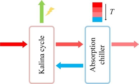
Figure 6 is the Sankey diagram of the integrated system, presenting the detailed distribution of exergy input, exergy destruction and electricity production. The lower part of this diagram represents the exergy inflow and the upper part indicates where the exergy is going. This figure shows that the low-grade waste heat can be efficiently converted into high-grade electrical power in the integrated system by consuming a small amount of electricity. Exergy input and destruction in the Kalina cycle are both larger, and considerable exergy destruction can be found in the generators, absorber, turbine, high-temperature recuperator, condenser and evaporator.

4.2. Advanced Exergy Analysis Results

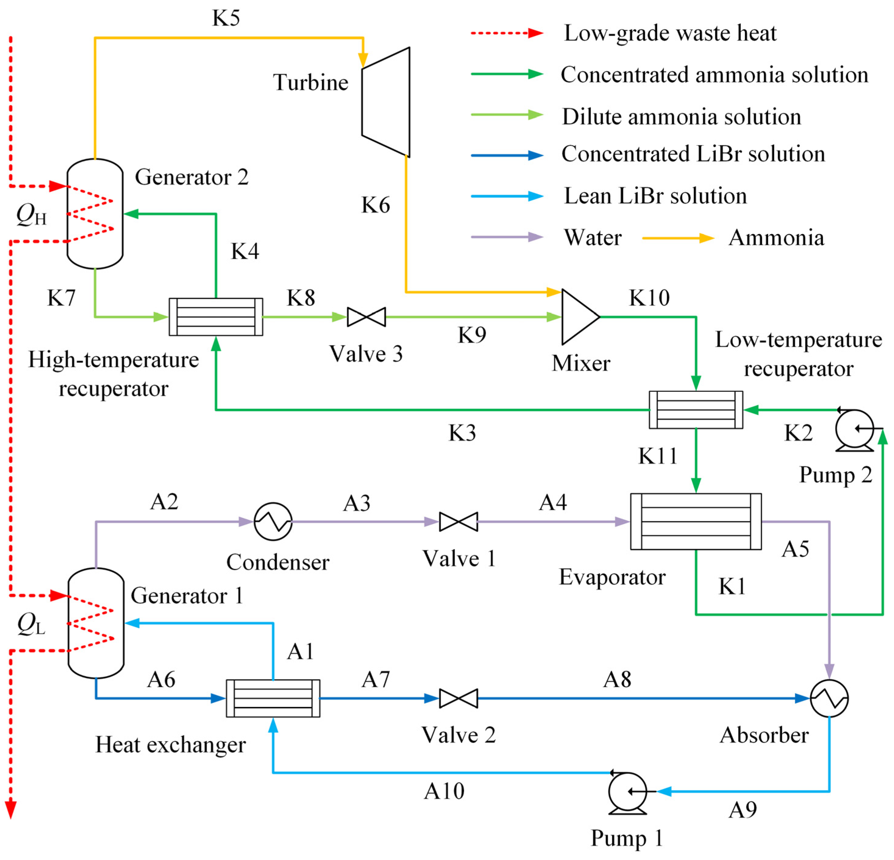
Physical properties, including mass fraction, temperature, pressure, vapor fraction, mass flow rate, mass enthalpy, as well as mass entropy of both the lithium bromide/water solution and ammonia/water solution, are obtained in the process simulation. Detailed simulation results of each stream in the real, unavoidable and ideal cycles are given in Supplementary Tables S1–S3. Mass concentrations of these two basic solutions are kept the same (55.5% for the LiBr/H2O solution and 70% for the ammonia solution). As the integrated system operates in the real, unavoidable and ideal conditions, working fluids have totally different mass concentrations. In the absorption refrigeration cycle, the strong solution has the highest mass fraction of 69% when the system operates in the ideal condition. This value is obviously larger than that of the real cycle (62%). This indicates that relatively more refrigerant vapor (H2O) is released from the basic solution in the generator. The mass fraction difference among different concentrated streams in the Kalina cycle is very obvious as well. More ammonia vapor escapes from the liquid solution in the ideal cycle, absorbing more heat in the generator. In the ideal condition, the condenser temperature of the absorption chiller (stream A3) is around 30 °C, lower than the corresponding value of 35 °C in the real condition. This allows the absorption chiller to operate at a lower high pressure. Similarly, the smaller minimum temperature difference of the evaporator in the ideal cycle results in much lower turbine exhaust outlet pressure (backpressure). Thus, the basic solution of the Kalina cycle reaches much lower low pressure (241 kPa lower than 293 kPa), increasing the turbine expansion ratio and electrical power generation. Mass vapor fractions are also influenced by different operation conditions. By comparing the mass flow rates among these three conditions, it can be noticed that for both the absorption refrigeration cycle and the power generation cycle, improving the component efficiency reduces the flow rates of the working fluids. The flow rate determines the size of a certain process which means that this integrated system will have a much compact structure when operating in the ideal condition. Mass enthalpy and mass entropy are obtained based on the status of each stream at different reference state. Thus, there are positive and negative values for these two working solutions. Then, these obtained results are used for exergy calculation of each component.
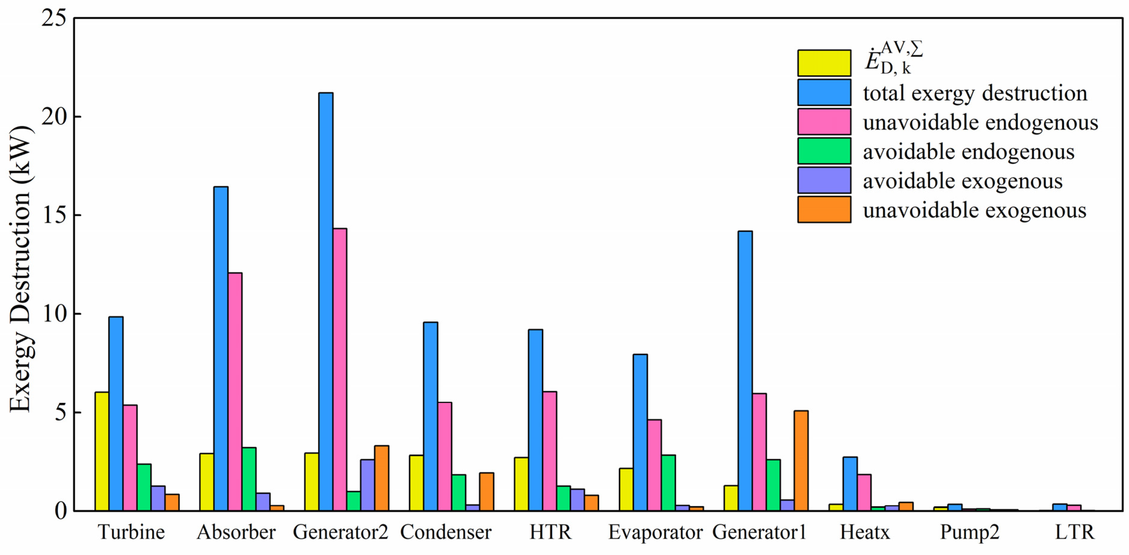
On the basis of exergy calculation for each component, detailed exergy destruction distribution has been obtained. The total exergy destruction, endogenous/exogenous exergy destruction, avoidable/unavoidable exergy destruction and avoidable endogenous/avoidable exogenous/unavoidable endogenous/unavoidable exogenous exergy destruction for each considered component are provided in Table 4. It should be mentioned that the electrical power consumption of the LiBr/H2O pump (Pump 1) is less than 0.01 kW due to small pressure increase. Hence, the exergy destruction distribution of this pump is not given as well. Among all the considered components, Generator 2, Absorber and Generator 1 have the highest total exergy destruction, followed by Turbine, Condenser, High-temperature recuperator, Evaporator, Heat exchanger, etc. Significant temperature mismatching between two different working streams could be the major reason for large exergy destruction in these heat exchangers [22]. Phase change and fluid mixing might also cause considerable exergy destruction in components such as generators, absorber and turbine, etc. Low-temperature recuperator and Pump 2 have the least total exergy destruction. Endogenous exergy destruction is the part that relies on the inefficiency of the considered component and the exogeneous part relies on the system structure and the inefficiency of the rest of the components. From the endogenous/exogenous exergy destruction results, the endogenous part is much more significant than the other one. Exergy destruction of all the considered components is almost endogenous. Generator 1 and Generator 2 have obviously higher exogenous exergy destruction, which indicates that these two generators are greatly influenced by the rest of the components. In the absorption refrigeration cycle, the largest amount of avoidable exergy destruction is in Absorber and Generator 1. Among all the components in the Kalina cycle, Generator 2 and Turbine have the most avoidable exergy destruction. Although the Condenser and High-temperature recuperator have nearly the same amount of total exergy destruction with Turbine, the avoidable exergy destruction of these two components is relatively lower. The unavoidable exergy destruction refers to the exergy destruction that is inevitable because of technological and manufacturing limitations. For instance, the limitations could be poor equipment design, failure to conform to design standards, unsatisfactory flow dynamics or gas–liquid interaction, inert gases in equipment, fouling problem and sizes limitation of equipment such as heat transfer area of heat exchangers, volume of storage tanks, etc. In present research, the unavoidable part is found to be larger than the avoidable part. It can be concluded that a large proportion of the destruction cannot be avoided by any means. By combining the two concepts, the total exergy destruction is further divided into four parts for a better understanding of the inefficiency of this integrated system. Those with higher avoidable endogenous destruction are worth exergy improvement investigations [41]. This means that more attention should be paid to the Absorber, Evaporator, Generator 1 and Turbine. The avoidable endogenous part of exergy destruction can be directly reduced by improving the considered component itself. The highest avoidable exogenous exergy destruction can be found in Generator 2, the Turbine and the High-temperature recuperator. To avoid this part in the considered component, structure optimization of the whole process or performance improvement on the rest components is recommended. Endogenous/exogenous distribution of the unavoidable exergy destruction provides the information about this inevitable part due to limitations of the considered component or limitations of the rest of the components and overall system design.
Detailed exergy destruction distribution of each considered component in the absorption chiller and the Kalina cycle is illustrated in Table 5. This table clearly presents the percentage of each part of the exergy destruction. The Evaporator, Absorber and Low-temperature recuperator have the highest proportion of endogenous exergy destruction and less than 10% of the exergy destruction is caused by extrinsic causes. Pump 2, Evaporator and Turbine are the components with more than 1/3 of the exergy destruction that can be avoided. The highest proportion of the avoidable endogenous part is in Evaporator, Pump 2 and Turbine. For the avoidable exogenous part, Pump 2, Turbine, Generator 2 and the High-temperature recuperator have the highest percentage of this part that is caused by external factors. The unavoidable endogenous part always occupies the highest proportion of the total amount, except for Pump 2.
To investigate how one component affects other components, detailed splitting on the exogenous exergy destruction has been achieved for each component, as given in Supplementary Table S4. The avoidable part of the exogenous exergy destruction has also been obtained. The splitting results for each considered component show that the interconnections among different components are not crucially important but rather complicated. It is the introduction of inefficiency in the rth component that changes the flow rates and thermodynamic properties of the working medium in the kth component. The values of exogenous exergy destruction caused by other components can be positive or negative [51]. The positive values indicate that introducing the irreversibility of the rth component into the process makes the exergetic performance of the kth component worse. The negative values stand for the opposite situation. If the exogenous exergy destruction corresponding to the rth component equals zero, that means this considered component is not influenced by the rth component at all. The expression ‘<0.01’ indicates a weak interaction between two components and that interaction can be neglected. It can be noticed that components in the Kalina cycle are basically not affected by those components completely in the absorption chiller (i.e., Generator 1, Condenser, Absorber and Heat exchanger). This can be explained as the absorption chiller recovers the thermal energy from the Kalina cycle, and hence it is the bottoming cycle of this power generation cycle. The working status of the components in the topping cycle determines the working status of the follow-up components, but not vice versa. The turbine seems to have considerable effect on the rest of the components. LTR causes negligible changes to other components. It is not obviously influenced by others either. Heat exchanger and Pump 2 also have no obvious influence on the rest of the components. The mexogenous exergy destruction is then calculated using the exogenous exergy destruction of the kth component and the sum of all the (n − 1) parts caused by inefficiency of the rth components. This mexogenous part is noteworthy in components such as Generator 1, Generator 2 and Turbine. The avoidable exogenous part is also very important because it indicates the achievable exogenous exergy-saving potential. The avoidable exogenous parts of Generator 1, Evaporator, Absorber and HTR are highly related to the generator of the Kalina cycle.
To evaluate the improvement priority for all the considered components, the avoidable exogenous part of other components that is caused by the considered component is summed up. This value is then combined with the avoidable endogenous part of this component as the major criterion of improvement priority in the whole system. All these exergy calculation results are shown in Table 6. Absorber, Evaporator and Generator 1 have the highest avoidable endogenous exergy destruction among all the considered components, while the summed values of these three components are negative. Turbine and Generator 2 have the highest and the second highest summed values of avoidable exogenous exergy destruction. As a result, the turbine possesses the highest E ˙ D ,   k AV ,   value of more than 6 kW, which far surpasses those values of all the other components. Thus, the first priority of improvement should be given to the turbine, and then Generator 2, Absorber, Condenser, High-temperature recuperator, Evaporator, etc. In contrast, Heat exchanger, Pump 2 and the Low-temperature recuperator hold the lowest E ˙ D ,   k AV ,   values of all. This indicates that the improvement on these components seems to be less important.
Figure 7 depicts the improvement priority and detailed exergy destruction. The total destruction and the avoidable endogenous part of the Turbine are both not highly ranked. However, it has a significant impact on the remaining components. Thus, efficiency improvement of the Turbine should be the primary consideration. Generator 2, Absorber, Condenser and the High-temperature recuperator have nearly the same level of improvement priority. The Absorber has the highest avoidable endogenous part, which can be avoided by improving the component itself. Generator 2 possesses a considerable amount of avoidable exogenous destruction that can be saved through efficiency improvement of the rest of the components. Hence, improvement of these two components could be placed at the second and the third position, following the turbine. Although Generator 1 has the third-largest exergy destruction among all the considered components, this generator does not have a strong effect on the overall exergy efficiency of this integrated system. However, improvement of Generator 1 is very necessary because it still has a considerable amount of avoidable exergy destruction. Compared with other considered components, the exergy-saving potential in the Heat exchanger is very poor and the total exergy destruction in Pump 2 and Low-temperature recuperator are absolutely insignificant.
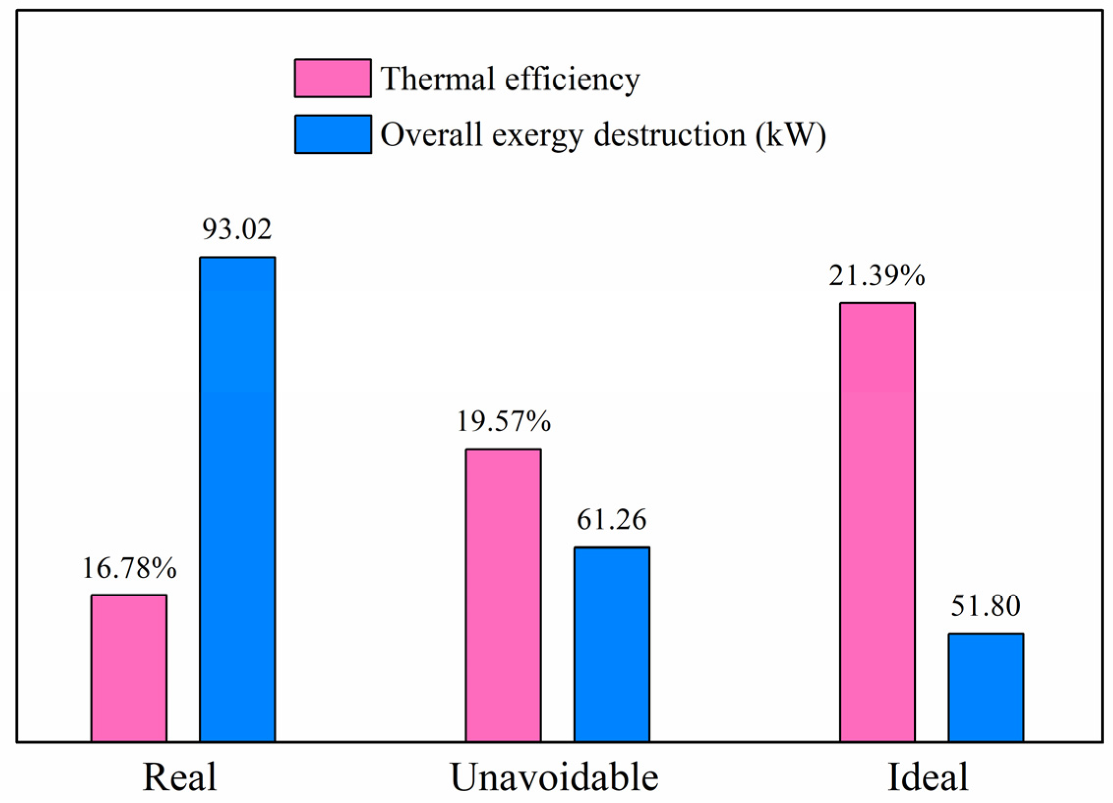
There are several important criteria for evaluating all the considered components and the whole system, including thermal efficiency and exergy destruction of the overall system (as shown in Figure 8), exergy efficiency, exergy destruction ratio, modified exergy efficiency, modified exergy destruction ratio and EIP (as given in Table 7). In the real condition, the thermal efficiency of this integrated system is 16.78%, with overall exergy destruction of 93.02 kW. The corresponding values are 19.57% and 61.26 kW for the unavoidable condition, and 21.39% and 51.80 kW for the ideal condition. When the integrated system operates in the improved conditions of the unavoidable and ideal cycles, the waste heat is recovered and utilized with higher efficiency. Additionally, the overall exergy destruction dramatically decreases.
By comparing the exergy efficiencies with the modified exergy efficiencies in Table 7, it can be found that the modified efficiencies of both individual components and the overall system have higher values. The modified values in the advanced exergy analysis are more reasonable because these values are calculated by removing the unavoidable and avoidable exogenous exergy destruction. These modified values refer to the exergetic performance with the utmost improvement on components or overall system. The modified relative exergy destruction ratio y k ,   total * of the component is found to be much lower than the relative exergy destruction ratio. The modified ratio indicates the relative avoidable endogenous exergy destruction of the considered component. For instance, Generator 2 has the highest value of relative exergy destruction ratio, but a relatively low modified relative exergy destruction ratio. This is because a huge amount of destruction of this generator is unavoidable and exogenous. EIP of the advanced analysis represents the unavoidable and avoidable exogenous exergy-destruction ratio of the considered component. For example, the Condenser has a low modified exergy efficiency but a high EIP value. This means that although the exergy destruction in the condenser is considerable, this destruction cannot be easily reduced because most of it is unavoidable or exogenous. Absorber and Generator 1 also have relatively high EIP values. In general, these modified values provide more useful information about the exergetic performance and improvement potential of both individual component and the overall system.

5. Conclusions

Conventional exergy analysis results show that the overall exergy efficiency is obtained as 35.52%. The exergy input and exergy destruction of the Kalina cycle are both larger than that of the absorption chiller. The largest exergy destruction occurs in the generator of the Kalina cycle, the absorber and generator of the absorption chiller. The low-grade waste heat can be efficiently converted into high-grade electrical power in this system by consuming a small amount of electricity. In the advanced analysis, exergy destruction of individual component is basically endogenous. Generators have relatively higher exogenous destruction; hence, generator performance is greatly influenced by the interactions among other components. Interconnections between different components are very complicated. Components in the KC are generally not influenced by the components in the bottoming cycle. The Absorber, Evaporator, Generator 1 and Turbine have the highest avoidable endogenous exergy destruction. The highest avoidable exogenous exergy destruction is in the generator, turbine and high-temperature recuperator of KC. Gas turbine holds the first priority of improvement because it has considerable avoidable endogenous exergy destruction and a strong effect on the remaining components. In addition, performance improvement on the heat exchanger of absorption chiller, the low-temperature recuperator and pump of KC only makes a little difference on the overall exergetic performance. The unavoidable destruction is always larger than the avoidable part which suggests that a large amount of exergy destruction cannot be avoided. The avoidable destruction occupies 24.60% of the overall exergy destruction and the avoidable endogenous part accounts for 16.64% of the total. Thus, there is considerable improvement potential in this integrated system. Based on the detailed and useful information provided in this research, specific optimization on the system design and operation will be conducted in our future efforts.

Supplementary Materials

The following supporting information can be downloaded at: https://www.mdpi.com/article/10.3390/pr10122608/s1, Table S1: Simulation results of the integrated system in real condition.; Table S2: Simulation results of the integrated system in unavoidable condition. Table S3: Simulation results of the integrated system in ideal condition. Table S4. Splitting on the exogenous destruction (kW).

Author Contributions

Funding acquisition, N.X.; Investigation, N.X.; Methodology, N.X.; Software, Z.Z.; Supervision, Z.L.; Validation, C.D.; Visualization, C.D.; Writing—original draft, N.X.; Writing—review and editing, Z.Z. All authors have read and agreed to the published version of the manuscript.

Funding

This research was funded by [National Natural Science Foundation of China] grant number [52206037], and the APC was funded by [National Natural Science Foundation of China].

Conflicts of Interest

The authors declare no conflict of interest.

Nomenclature

E ˙ Exergy flow rate (kW).
Ex0Standard chemical exergy (kJ/mol).
HEnthalpy (kW).
hSpecific enthalpy, mass enthalpy (kJ/kg).
mMass flow rate (kg/s).
PPressure (kPa).
QHeat flow rate (kW).
RUniversal gas constant (kJ·mol−1·K−1).
SEntropy (kW/K).
sSpecific entropy, mass entropy (kJ·kg−1·K−1).
TTemperature (°C).
ΔTminThe minimum temperature difference (°C).
WWork or electrical power output (kW).
XMass fraction.
xMole fraction.
yExergy destruction ratio.
Greek symbols
εExergy efficiency.
ηComponent efficiency.
ηpOverall efficiency of pump.
ηtOverall efficiency of turbine.
Superscripts
*Modified.
AVAvoidable exergy destruction.
ENEndogenous exergy destruction.
EXExogenous exergy destruction.
IIHybrid cycle II.
kThe kth component.
mexoMexogenous.
rThe rth component.
UNUnavoidable exergy destruction.
Subscripts
0Reference state.
DDestruction.
FFuel.
HHigh temperature.
iThe substance component i.
kThe kth component.
LLow temperature.
nThe total component number.
PProduct.
rThe rth component.
totalThe overall system.
Abbreviations
AVENAvoidable endogenous.
AVEXAvoidable exogenous.
EIPExergy improvement potential.
EvapEvaporator.
HTRHigh-temperature recuperator.
HeatxHeat exchanger.
KCKalina cycle.
LTRLow-temperature recuperator.
ORCOrganic Rankine cycle.
UNENUnavoidable endogenous.
UNEXUnavoidable exogenous.

References

  1. Su, Z.; Zhang, M.; Xu, P.; Zhao, Z.; Wang, Z.; Huang, H.; Ouyang, T. Opportunities and strategies for multigrade waste heat utilization in various industries: A recent review. Energy Convers. Manag. 2021, 229, 113769. [Google Scholar] [CrossRef]
  2. Zhang, X.; He, M.; Zhang, Y. A Review of Research on the Kalina Cycle. Renew. Sustain. Energy Rev. 2012, 16, 5309–5318. [Google Scholar] [CrossRef]
  3. Nikbakhti, R.; Wang, X.; Hussein, A.K.; Iranmanesh, A. Absorption cooling systems—Review of various techniques for energy performance enhancement. Alex. Eng. J. 2020, 59, 707–738. [Google Scholar] [CrossRef]
  4. Heng, Z.; Feipeng, C.; Yang, L.; Haiping, C.; Kai, L.; Boran, Y. The performance analysis of a LCPV/T assisted absorption refrigeration system. Renew. Energy 2019, 143, 1852–1864. [Google Scholar] [CrossRef]
  5. Jovijari, F.; Kosarineia, A.; Mehrpooya, M.; Nabhani, N. Advanced exergy analysis of the natural gas liquid recovery process. Therm. Sci. 2022, 26, 2287–2300. [Google Scholar] [CrossRef]
  6. Cao, L.; Wang, J.; Wang, H.; Zhao, P.; Dai, Y. Thermodynamic analysis of a Kalina-based combined cooling and power cycle driven by low-grade heat source. Appl. Therm. Eng. 2017, 111, 8–19. [Google Scholar] [CrossRef]
  7. Wang, J.; Wang, J.; Zhao, P.; Dai, Y. Thermodynamic analysis of a new combined cooling and power system using ammonia–water mixture. Energy Convers. Manag. 2016, 117, 335–342. [Google Scholar] [CrossRef]
  8. Shokati, N.; Ranjbar, F.; Yari, M. A comprehensive exergoeconomic analysis of absorption power and cooling cogeneration cycles based on Kalina, part 1: Simulation. Energy Convers. Manag. 2018, 158, 437–459. [Google Scholar] [CrossRef]
  9. Shokati, N.; Ranjbar, F.; Yari, M. A Comprehensive Exergoeconomic Analysis of Absorption Power and Cooling Cogeneration Cycles Based on Kalina, Part 2: Parametric Study and Optimization. Energy Convers. Manag. 2018, 161, 74–103. [Google Scholar] [CrossRef]
  10. Qu, W.; Hong, H.; Su, B.; Tang, S.; Jin, H. A concentrating photovoltaic/Kalina cycle coupled with absorption chiller. Appl. Energy 2018, 224, 481–493. [Google Scholar] [CrossRef]
  11. Rashidi, J.; Yoo, C.K. Exergetic and exergoeconomic studies of two highly efficient power-cooling cogeneration systems based on the Kalina and absorption refrigeration cycles. Appl. Therm. Eng. 2017, 124, 1023–1037. [Google Scholar] [CrossRef]
  12. Rashidi, J.; Ifaei, P.; Esfahani, I.J.; Ataei, A.; Yoo, C.K. Thermodynamic and economic studies of two new high efficient power-cooling cogeneration systems based on Kalina and absorption refrigeration cycles. Energy Convers. Manag. 2016, 127, 170–186. [Google Scholar] [CrossRef]
  13. Aghbashlo, M.; Khounani, Z.; Hosseinzadeh-Bandbafha, H.; Gupta, V.K.; Amiri, H.; Lam, S.S.; Morosuk, T.; Tabatabaei, M. Exergoenvironmental analysis of bioenergy systems: A comprehensive review. Renew. Sustain. Energy Rev. 2021, 149, 111399. [Google Scholar] [CrossRef]
  14. Song, M.T.; Zhuang, Y.; Zhang, L.; Wang, C.; Du, J.; Shen, S.Q. Advanced exergy analysis for the solid oxide fuel cell system combined with a kinetic-based modeling pre-reformer. Energy Convers. Manag. 2021, 245, 114560. [Google Scholar] [CrossRef]
  15. Aktemur, C.; Hacipasaoglu, S.G. An Application of Conventional and Advanced Exergy Approaches on a R41/R1233zd(E) Cascade Refrigeration System under Optimum Conditions. J. Therm. Eng. 2022, 8, 182–201. [Google Scholar] [CrossRef]
  16. Ledari, M.B.; Saboohi, Y.; Valero, A.; Azamian, S. Exergy Analysis of a Bio-System: Soil–Plant Interaction. Entropy 2020, 23, 3. [Google Scholar] [CrossRef]
  17. Liu, Z.; Liu, B.; Guo, J.; Xin, X.; Yang, X. Conventional and advanced exergy analysis of a novel transcritical compressed carbon dioxide energy storage system. Energy Convers. Manag. 2019, 198, 111807. [Google Scholar] [CrossRef]
  18. Kelly, S.; Tsatsaronis, G.; Morosuk, T. Advanced exergetic analysis: Approaches for splitting the exergy destruction into endogenous and exogenous parts. Energy 2009, 34, 384–391. [Google Scholar] [CrossRef]
  19. Tsatsaronis, G.; Morosuk, T. Advanced exergetic analysis of a novel system for generating electricity and vaporizing liquefied natural gas. Energy 2010, 35, 820–829. [Google Scholar] [CrossRef]
  20. Cao, Y.; Rostamian, F.; Ebadollahi, M.; Bezaatpour, M.; Ghaebi, H. Advanced exergy assessment of a solar absorption power cycle. Renew. Energy 2022, 183, 561–574. [Google Scholar] [CrossRef]
  21. Wang, Y.; Qin, G.; Zhang, Y.; Yang, S.; Liu, C.; Jia, C.; Cui, Q. Conventional and advanced exergy analyses of an organic Rankine cycle by using the thermodynamic cycle approach. Energy Sci. Eng. 2021, 9, 2474–2492. [Google Scholar] [CrossRef]
  22. Nami, H.; Nemati, A.; Fard, F.J. Conventional and advanced exergy analyses of a geothermal driven dual fluid organic Rankine cycle (ORC). Appl. Therm. Eng. 2017, 122, 59–70. [Google Scholar] [CrossRef]
  23. Liu, Z.; Liu, Z.; Yang, X.; Zhai, H.; Yang, X. Advanced exergy and exergoeconomic analysis of a novel liquid carbon dioxide energy storage system. Energy Convers. Manag. 2020, 205, 112391. [Google Scholar] [CrossRef]
  24. Yang, X.; Yang, S.; Wang, H.; Yu, Z.; Liu, Z.; Zhang, W. Parametric assessment, multi-objective optimization and advanced exergy analysis of a combined thermal-compressed air energy storage with an ejector-assisted Kalina cycle. Energy 2021, 239, 122148. [Google Scholar] [CrossRef]
  25. Khoshgoftar Manesh, M.; Ghadikolaei, R.; Modabber, H.; Onishi, V. Integration of a Combined Cycle Power Plant with Med-Ro Desalination Based on Conventional and Advanced Exergy, Exergoeconomic, and Exergoenvironmental Analyses. Processes 2020, 9, 59. [Google Scholar] [CrossRef]
  26. Manesh, M.H.K.; Abdolmaleki, M.; Modabber, H.V.; Rosen, M.A. Dynamic Advanced Exergetic, Exergoeconomic, and Environmental Analyses of a Hybrid Solar City Gate Station. J. Energy Resour. Technol. 2021, 143, 102105. [Google Scholar] [CrossRef]
  27. Khoshgoftar Manesh, M.H.; Ghorbani, S.; Blanco-Marigorta, A.M. Optimal Design and Analysis of a Combined Freshwater-Power Generation System Based on Integrated Solid Oxide Fuel Cell-Gas Turbine-Organic Rankine Cycle-Multi Effect Distillation System. Appl. Therm. Eng. 2022, 211, 118438. [Google Scholar] [CrossRef]
  28. Liu, X.; Yan, X.; Liu, X.; Liu, Z.; Zhang, W. Comprehensive Evaluation of a Novel Liquid Carbon Dioxide Energy Storage System with Cold Recuperator: Energy, Conventional Exergy and Advanced Exergy Analysis. Energy Convers. Manag. 2021, 250, 114909. [Google Scholar] [CrossRef]
  29. Meng, N.; Li, T.; Kong, X.; Gao, X. Advanced exergy and exergoeconomic analyses and a case study of a novel trans-critical CO2 cycle with pressurization process for hot dry rock. Energy Convers. Manag. 2021, 246, 114687. [Google Scholar] [CrossRef]
  30. Wu, J.; Wang, N. Life cycle environmental impact of system irreversibility based on advanced exergy analysis: A case study. J. Environ. Manag. 2021, 296, 113151. [Google Scholar] [CrossRef]
  31. Yousefizadeh Dibazar, S.; Salehi, G.; Davarpanah, A. Comparison of Exergy and Advanced Exergy Analysis in Three Different Organic Rankine Cycles. Processes 2020, 8, 586. [Google Scholar] [CrossRef]
  32. Jadidi, E.; Manesh, M.H.K.; Delpisheh, M.; Onishi, V.C. Advanced Exergy, Exergoeconomic, and Exergoenvironmental Analyses of Integrated Solar-Assisted Gasification Cycle for Producing Power and Steam from Heavy Refinery Fuels. Energies 2021, 14, 8409. [Google Scholar] [CrossRef]
  33. Caglayan, H.; Caliskan, H. Advanced Exergy Analyses and Optimization of a Cogeneration System for Ceramic Industry by Considering Endogenous, Exogenous, Avoidable and Unavoidable Exergies under Different Environmental Conditions. Renew. Sustain. Energy Rev. 2021, 140, 110730. [Google Scholar] [CrossRef]
  34. Adun, H.; Adedeji, M.; Adebayo, V.; Shefik, A.; Bamisile, O.; Kavaz, D.; Dagbasi, M. Multi-objective optimization and energy/exergy analysis of a ternary nanofluid based parabolic trough solar collector integrated with kalina cycle. Sol. Energy Mater. Sol. Cells 2021, 231, 111322. [Google Scholar] [CrossRef]
  35. Liu, Z.; Xie, N.; Yang, S. Thermodynamic and parametric analysis of a coupled LiBr/H2O absorption chiller/Kalina cycle for cascade utilization of low-grade waste heat. Energy Convers. Manag. 2020, 205, 112370. [Google Scholar] [CrossRef]
  36. He, J.; Liu, C.; Xu, X.; Li, Y.; Wu, S.; Xu, J. Performance research on modified KCS (Kalina cycle system) 11 without throttle valve. Energy 2014, 64, 389–397. [Google Scholar] [CrossRef]
  37. Akbari Kordlar, M.; Mahmoudi, S.M.S.; Talati, F.; Yari, M.; Mosaffa, A.H. A New Flexible Geothermal Based Cogeneration System Producing Power and Refrigeration, Part Two: The Influence of Ambient Temperature. Renew. Energy 2019, 134, 875–887. [Google Scholar] [CrossRef]
  38. Jing, X.; Zheng, D. Effect of cycle coupling-configuration on energy cascade utilization for a new power and cooling cogeneration cycle. Energy Convers. Manag. 2014, 78, 58–64. [Google Scholar] [CrossRef]
  39. Gräbner, M.; Meyer, B. Performance and exergy analysis of the current developments in coal gasification technology. Fuel 2014, 116, 910–920. [Google Scholar] [CrossRef]
  40. Zhou, J.; Ling, P.; Su, S.; Xu, J.; Xu, K.; Wang, Y.; Hu, S.; Zhu, M.; Xiang, J. Exergy analysis of a 1000 MW single reheat advanced supercritical carbon dioxide coal-fired partial flow power plant. Fuel 2019, 255. [Google Scholar] [CrossRef]
  41. Fallah, M.; Mahmoudi, S.M.S.; Yari, M.; Ghiasi, R.A. Advanced exergy analysis of the Kalina cycle applied for low temperature enhanced geothermal system. Energy Convers. Manag. 2016, 108, 190–201. [Google Scholar] [CrossRef]
  42. Bai, T.; Yu, J.; Yan, G. Advanced exergy analyses of an ejector expansion transcritical CO2 refrigeration system. Energy Convers. Manag. 2016, 126, 850–861. [Google Scholar] [CrossRef]
  43. Morosuk, T.; Tsatsaronis, G. Advanced exergy-based methods used to understand and improve energy-conversion systems. Energy 2019, 169, 238–246. [Google Scholar] [CrossRef]
  44. Ansarinasab, H.; Mehrpooya, M.; Mohammadi, A. Advanced exergy and exergoeconomic analyses of a hydrogen liquefaction plant equipped with mixed refrigerant system. J. Clean. Prod. 2017, 144, 248–259. [Google Scholar] [CrossRef]
  45. Dai, B.; Zhu, K.; Wang, Y.; Sun, Z.; Liu, Z. Evaluation of organic Rankine cycle by using hydrocarbons as working fluids: Advanced exergy and advanced exergoeconomic analyses. Energy Convers. Manag. 2019, 197. [Google Scholar] [CrossRef]
  46. Keçebaş, A.; Gökgedik, H. Thermodynamic evaluation of a geothermal power plant for advanced exergy analysis. Energy 2015, 88, 746–755. [Google Scholar] [CrossRef]
  47. Mehrpooya, M.; Mousavi, S.A. Advanced exergoeconomic assessment of a solar-driven Kalina cycle. Energy Convers. Manag. 2018, 178, 78–91. [Google Scholar] [CrossRef]
  48. Galindo, J.; Ruiz, S.; Dolz, V.; Royo-Pascual, L. Advanced exergy analysis for a bottoming organic rankine cycle coupled to an internal combustion engine. Energy Convers. Manag. 2016, 126, 217–227. [Google Scholar] [CrossRef]
  49. Gong, S.; Goni Boulama, K. Advanced exergy analysis of an absorption cooling machine: Effects of the difference between the condensation and absorption temperatures. Int. J. Refrig. 2015, 59, 224–234. [Google Scholar] [CrossRef]
  50. Koroglu, T.; Sogut, O.S. Conventional and advanced exergy analyses of a marine steam power plant. Energy 2018, 163, 392–403. [Google Scholar] [CrossRef]
  51. Wang, L.; Yang, Y.; Morosuk, T.; Tsatsaronis, G. Advanced Thermodynamic Analysis and Evaluation of a Supercritical Power Plant. Energies 2012, 5, 1850–1863. [Google Scholar] [CrossRef]
Figure 1. LiBr/H2O absorption chiller/KC integrated system.
Processes 10 02608 g001
Figure 2. Temperature-entropy diagram of the integrated system and individual KC.
Processes 10 02608 g002
Figure 3. Flowchart for exergy destruction calculation.
Processes 10 02608 g003
Figure 4. Exergy input, exergy destruction and electrical power output of the integrated system.
Processes 10 02608 g004
Figure 5. Exergy destruction of each equipment.
Processes 10 02608 g005
Figure 6. Sankey diagram of the integrated system.
Processes 10 02608 g006
Figure 7. Improvement potential and detailed exergy destruction.
Processes 10 02608 g007
Figure 8. Thermal efficiency and overall exergy destruction for different conditions.
Processes 10 02608 g008
Table 1. Mathematical equations for each component.
ComponentEnergy Balance EquationExergy Balance Equation
Generator 1 m A 1 h A 1 + Q L = m A 2 h A 2 + m A 6 h A 6 E ˙ A 1 + E ˙ QL = E ˙ A 2 + E ˙ A 6 + E ˙ D ,   generator   1
Condenser Q condenser = m A 2 h A 2 m A 3 h A 3 E ˙ A 2 = E ˙ A 3 + E ˙ D ,   condenser
Valve 1 m A 3 h A 3 = m A 4 h A 4 E ˙ A 3 = E ˙ A 4 + E ˙ D ,   valve   1
Evaporator m A 4 h A 4 m A 5 h A 5 = m K 11 h K 11 m K 1 h K 1 E ˙ A 4 + E ˙ K 11 = E ˙ A 5 + E ˙ K 1 + E ˙ D ,   evap
Absorber m A 5 h A 5 + m A 8 h A 8 = m A 9 h A 9 E ˙ A 5 + E ˙ A 8 = E ˙ A 9 + E ˙ D ,   absorber
Heat exchanger m A 6 h A 6 m A 7 h A 7 = m A 1 h A 1 m A 10 h A 10 E ˙ A 6 + E ˙ A 10 = E ˙ A 1 + E ˙ A 7 + E ˙ D ,   heatx
Valve 2 m A 7 h A 7 = m A 8 h A 8 E ˙ A 7 = E ˙ A 8 + E ˙ D ,   valve   2
Pump 1 W pump   1 = 1 η p m A 9 ( h A 10 h A 9 ) E ˙ A 9 + W ˙ pump   1 = E ˙ A 10 + E ˙ D ,   pump   1
Generator 2 m K 4 h K 4 + Q H = m K 5 h K 5 + m K 7 h K 7 E ˙ K 4 + E ˙ QH = E ˙ K 5 + E ˙ K 7 + E ˙ D ,   generator   2
Turbine W turbine = m K 5 ( h K 5 h K 6 ) × η t E ˙ K 5 = E ˙ K 6 + W ˙ turbine + E ˙ D ,   turbine
Mixer m K 6 h K 6 + m K 9 h K 9 = m K 10 h K 10 E ˙ K 6 + E ˙ K 9 = E ˙ K 10 + E ˙ D ,   mixer
HTR m K 7 h K 7 m K 8 h K 8 = m K 4 h K 4 m K 3 h K 3   E ˙ K 3 + E ˙ K 7 = E ˙ K 4 + E ˙ K 8 + E ˙ D ,   HTR
Valve 3 m K 8 h K 8 = m K 9 h K 9 E ˙ K 8 = E ˙ K 9 + E ˙ D ,   valve   3
LTR m K 10 h K 10 m K 11 h K 11 = m K 3 h K 3 m K 2 h K 2   E ˙ K 2 + E ˙ K 10 = E ˙ K 3 + E ˙ K 11 + E ˙ D ,   LTR
Pump 2 W pump   2 = 1 η p m K 1 ( h K 2 h K 1 )   E ˙ K 1 + W ˙ pump   2 = E ˙ K 2 + E ˙ D ,   pump   2
Table 2. Validation with published literature [10].
Stream No.Temperature (℃)Pressure (kPa)Concentration (wt%)Flow Rate (kg/h)
This WorkRef.This WorkRef.This WorkRef.This WorkRef.
s119.620.04704700.700.70132.76132.76
s221.321.7700070000.700.70132.76132.76
s363.563.9700070000.700.70132.76132.76
s496.196.8700070000.700.70132.76132.76
s5190.0190.0700070000.700.70132.76132.76
s6190.0190.0700070000.830.8394.6394.33
s780.280.34704700.830.8394.6394.33
s873.973.94704700.700.70132.76132.76
s958.158.14704700.700.70132.76132.76
s1032.032.04704700.700.70132.76132.76
s11190.0190.0700070000.370.3738.1338.43
s1273.973.9700070000.370.3738.1338.43
s1361.461.34704700.370.3738.1338.43
Table 3. Operational parameters in real, unavoidable and ideal conditions [41,48,49,50].
ComponentRealUnavoidableIdeal
Generator 1ΔTmin = 10 °CΔTmin = 3 °CΔTmin = 0 °C
CondenserΔTmin = 5 °CΔTmin = 2 °CΔTmin = 0 °C
EvaporatorΔTmin = 5 °CΔTmin = 2 °CΔTmin = 0 °C
AbsorberΔTmin = 5 °CΔTmin = 2 °CΔTmin = 0 °C
Heat exchangerΔTmin = 5 °CΔTmin = 2 °CΔTmin = 0 °C
Pump 1η = 0.90η =0.95η = 1
Generator 2ΔTmin = 10 °CΔTmin = 3 °CΔTmin = 0 °C
Turbineη = 0.88η = 0.95η = 1
High-temperature recuperatorΔTmin = 5 °CΔTmin = 2 °CΔTmin = 0 °C
Low-temperature recuperatorΔTmin = 5 °CΔTmin = 2 °CΔTmin = 0 °C
Pump 2η = 0.90η = 0.95η = 1
Table 4. Exergy destruction (kW) in each considered component.
Component E ˙ D ,   k E ˙ D ,   k EN E ˙ D ,   k EX E ˙ D ,   k AV E ˙ D ,   k UN E ˙ D ,   k AV E ˙ D ,   k UN
E ˙ D ,   k AV ,   EN E ˙ D ,   k AV ,   EX E ˙ D ,   k UN ,   EN E ˙ D ,   k UN ,   EX
Generator 114.208.565.633.1611.032.610.565.955.08
Condenser9.577.342.232.147.431.840.305.501.93
Evaporator7.947.460.483.114.832.830.284.630.20
Absorber16.4415.291.164.1112.343.210.9012.080.26
Heatx2.732.040.690.462.270.200.261.840.43
Pump 20.340.200.130.170.160.110.070.100.07
Generator 221.2115.305.913.5817.630.982.6014.323.31
Turbine9.857.742.113.646.212.371.275.370.84
HTR9.207.311.892.366.851.261.106.050.79
LTR0.350.330.020.040.300.030.010.290.01
Table 5. Exergy destruction distribution of each considered component.
Component E ˙ D ,   k EN E ˙ D ,   k EX E ˙ D ,   k AV E ˙ D ,   k UN E ˙ D ,   k AV E ˙ D ,   k UN
E ˙ D ,   k AV ,   EN E ˙ D ,   k AV ,   EX E ˙ D ,   k UN ,   EN E ˙ D ,   k UN ,   EX
Generator 160.31%39.69%22.28%77.72%18.36%3.92%41.94%35.78%
Condenser76.71%23.29%22.37%77.63%19.21%3.15%57.50%20.14%
Evaporator93.92%6.08%39.13%60.87%35.61%3.53%58.31%2.56%
Absorber92.97%7.03%24.97%75.03%19.53%5.44%73.44%1.59%
Heatx74.65%25.35%16.79%83.21%7.30%9.50%67.36%15.85%
Pump 260.22%39.78%51.58%48.42%31.89%19.68%28.33%20.09%
Generator 272.13%27.87%16.88%83.12%4.63%12.25%67.50%15.62%
Turbine78.57%21.43%36.93%63.07%24.08%12.85%54.50%8.58%
HTR79.43%20.57%25.61%74.39%13.64%11.97%65.79%8.60%
LTR93.99%6.01%12.87%87.13%9.36%3.51%84.63%2.50%
Table 6. Component improvement potential.
Component E ˙ D ,   k AV ,   EN (kW) r = 1 r k n 1 E ˙ D ,   r AV ,   EX ,   k (kW) E ˙ D ,   k AV ,   (kW)
Generator 12.61−1.321.29
Condenser1.840.982.82
Evaporator2.83−0.672.16
Absorber3.21−0.312.91
Heatx0.200.130.33
Pump 20.110.080.18
Generator 20.981.952.93
Turbine2.373.656.02
HTR1.261.462.71
LTR0.03<0.010.03
Table 7. Exergy efficiency, exergy destruction ratio and EIP.
Component E ˙ D ,   k Conventional Exergy AnalysisAdvanced Exergy Analysis
ε k   y k   y k ,   total   ε k *   y k ,   total *   EIP %
Generator 114.2097.602.4015.2699.552.801.96
Condenser9.5736.2963.7110.2974.781.9851.47
Evaporator7.9499.900.108.5499.963.040.06
Absorber16.4496.953.0517.6899.393.452.46
Heatx2.7399.750.252.9499.980.210.23
Pump 20.3499.990.010.3699.990.120.01
Generator 221.2199.730.2722.8099.991.050.25
Turbine9.8599.730.2710.5999.942.550.20
HTR9.2099.920.089.8999.991.350.07
LTR0.3599.990.010.3799.990.030.01
Other1.1999.980.021.28///
Overall system93.02 ε total %35.52 ε total *   %76.87
Publisher’s Note: MDPI stays neutral with regard to jurisdictional claims in published maps and institutional affiliations.

