Abstract
The modeling of the paint atomization process is a barrier in computational fluid dynamics numerical simulation for the whole process of air spraying, and seriously restricts robot intelligent spray gun trajectory planning and the improvement of coating quality. Consequently, a multi-scale paint atomization model based on the hybrid Euler–Lagrange method was established in this paper, which included a large liquid micelle motion model, a particle motion model, and a turbulence flow model. The Euler method was adopted to capture the gas–liquid interface in the atomization flow field to describe the deformation and motion of large liquid micelles. The identification and transformation mechanisms of large liquid micelles and small particles were constructed by the particle motion model, and the motion of small droplets generated by paint atomization was tracked by the Lagrange method. The turbulence motion of the fluid in the process of paint atomization was described by a two-equation turbulence model. The model calculation method consisting of a finite-volume model, an adaptive hexcore mesh technique and a pressure-based coupled algorithm was established. The multi-scale atomization model was solved and model validation was carried out, which included mesh independence verification and model reliability analysis. The numerical simulation results predicted the atomization flow field parameters, paint atomization shapes, and the changing process from paint to liquid droplets, which was consistent with the experimental data. As a result, the established multi-scale atomization model in this paper is reliable for studying the paint atomization process of air spraying.
1. Introduction
The poor coating uniformity of painting on complex surfaces is a major problem in the quality control of robot spraying, with the main reason being that spray gun trajectory planning on complex surfaces is very difficult [1,2,3]. With the development of computer simulation technology, air spray gun trajectory planning has gradually improved from inputting empirical parameters to the computational fluid dynamics (CFD) simulation of the spraying process [4,5,6]. The spraying process includes paint atomization and spray film formation. At present, the CFD can simulate the static and dynamic spraying of the spray film-forming process, and the mechanisms and laws of spray film formation have been studied in depth [7,8,9,10,11,12,13]. In contrast, there is less research using CFD in the paint atomization process [11]. The atomization flow field parameters obtained from the paint atomization model are the initial conditions for spray film-forming simulation and are also indispensable parts of the whole simulation process of air spraying. In other words, reasonable CFD atomization process modeling plays a very important role in robot intelligent spray trajectory planning and coating quality control on complex surfaces.
Multi-phase flow methods suitable for modeling the atomization process of air spraying have been provided in CFD, divided into the simple engineering model method, the direct numerical simulation (DNS)-like method and the multi-scale simulation method [14].
The simple engineering model method refers to the empirical or semi-empirical atomization model, e.g., the Rosin–Rammler distribution [15,16] and the log-normal distribution [17,18] in droplet diameter distribution, as well as the TAB (Taylor Analogy Breakup) model [19,20,21]. Fogliati et al. [22] first used the simple engineering model method to study the air spraying film-forming process. The advantages of the previously mentioned models are the small amount of computation and the convenience of calculation coupled with the spray flow field. However, the general applicability and accuracy are poor due to the oversimplification of physical processes, and human factors have a great impact on the calculation results.
Subsequently, Xie et al. [13], Li et al. [20], and Andersson [21] used the TAB model to study the particle size distribution of paint droplets in the initial spray flow field. Droplet motion was simply treated as spring oscillator motion in the TAB model, and the critical conditions of droplet breakage and particle size distribution were determined according to the empirical hypothesis, which can only describe the secondary atomization process of paint. In addition, the preconditions of the TAB model must be obtained by experiments.
In the DNS-like method, the liquid atomization process is directly identified using interface capture technology to reveal a very fine atomization structure, which is of great significance to study the atomization mechanism [23,24]. Based on the DNS-like method, Chen et al. [25] established an air spraying atomization model and carried out two-dimensional paint atomization simulation. However, the computational effort required increased sharply with the increase in the number of paint droplets in the atomization flow field, which is not suitable for the numerical simulation of the whole atomization process.
The multi-scale simulation method was put forward to make up for the deficiency of the simple engineering model method and the DNS-like method. On the one hand, the simple engineering model method ignored too many factors, leading to a lack of precision. On the other hand, the DNS-like atomization process was too detailed, leading to a huge increase in computational effort required. The large-scale liquid micelle were simulated by the DNS-like method, which can determine the fine motion process of large fluid micelles. In contrast, the droplets were tracked by the Lagrangian method, which can greatly reduce the computational effort required.
In recent years, multi-scale simulation theory has been developed rapidly and applied in the study of fuel jet atomization and combustion [26]. Li et al. [27] established a coupling level set and volume of fluid (CLSVOF) model to track the motion of bulk liquid in multi-scale simulation for research on the atomization of liquid fuel. When the volume of the liquid phase was less than the preset value and the shape was approximately circular, the droplet was converted into small particles; thus, the motion model of small particles was established by the Lagrange particle tracking (LPT) method. Compared with the DNS-like method, the computational effort required was greatly reduced, and the main characteristics of large-scale liquid micelles were also relatively accurate. Estivalèzes et al. [28] applied the improved multi-scale Euler–Lagrange method to study the primary atomization of liquid fuel and obtained good results. A new feasible scheme was provided by using the multi-scale simulation method; however, scholars have not yet adopted this method in the study of air spraying atomization.
Based on the multi-scale simulation method, the Euler method was applied to model the paint liquid micelles generated in the primary atomization process, and the Lagrange method was used to describe the flow of small droplets in the atomization flow field. The identification and transformation mechanisms of large liquid micelles and small liquid droplets were established, and the whole simulation process model of paint atomization was described by the two-equation turbulence model. The computational method consisting of the finite-volume method (FVM), the adaptive hexcore mesh refinement technique, and the pressure-based coupled algorithm, which was constructed to solve the atomization model. The correctness of the numerical model, including mesh validity and model credibility analysis, was verified by numerical simulation and the spraying experiment.
The rest of this paper is divided into four parts: the mathematical expression of the atomization model is detailed in the Section 2; the solution of an example model is included in the Section 3; and the Section 4 consists of model validation, including mesh independence verification and model credibility analysis.
2. Mathematical Model
2.1. Motion Model of Large Paint Liquid Micelle
The large liquid micelle motion model of paint was applied to simulate the motion during the period from entering the atomization flow field to being converted into small droplets. As a result, the focus of this simulation process is to identify the interface between the air phase and the large liquid micelles of paint. In this paper, the volume of fluid (VOF) model based on the Eulerian method was used to track the gas–liquid interface in the atomization process.
In the transport equation of the VOF model, each variable and attribute parameter was shared by all phases and determined by the volume fraction of each. For any control body in the atomization space, the constraint condition of the volume fraction of the air phase (main phase, ) and paint phase (secondary phase, ) is shown as follows [25]:
In the process of air spraying atomization, one can assume that the air and paint are both incompressible fluids. On the one hand, the mass transfer and heat conduction can be ignored due to the transitory atomization time of paint. On the other hand, the continuity and momentum equation were decoupled in an incompressible flow. The mass conservation equation and momentum conservation equation of the gas–liquid two-phase flow in the atomization process are shown as follows:
where , , and are the volume fraction, the density (kg/m3), and the velocity (m/s) of phase, respectively. When or replaces the subscript , they become the paint phase and air phase, respectively. represents the pressure (N/m2) exerted by the two phases, is the dynamic viscosity (N·s/m2), is the local gravitational acceleration (m/s2), and represents the source term generated by the surface tension . The concrete expression can be described as follows according to Brackbill’s continuum surface force (CSF) model [29]:
where is the surface tension (N/m2), is the interface curvature (m−1), , and is the unit normal vector, .
2.2. Paint Particle Motion Model
The paint particle motion model includes candidate droplet identification, the shifting mechanism, and the droplet transport model. The latter describes the paint droplet motion in the atomization flow field by tracking its location and velocity.
2.2.1. Droplet Identification and Transformation Mechanism
Before being converted into discrete phase particles for tracking, it should be identified whether the candidate droplet structure generated in the atomization process meets the shifting condition. The adaptive mesh refinement was located at the liquid–gas interface, and small droplets were always resolved by the finest refinement level, so the identification procedure described below was performed exclusively on the finest level. A neighbor searching algorithm [30] was used in the identification procedure, as shown in Figure 1.
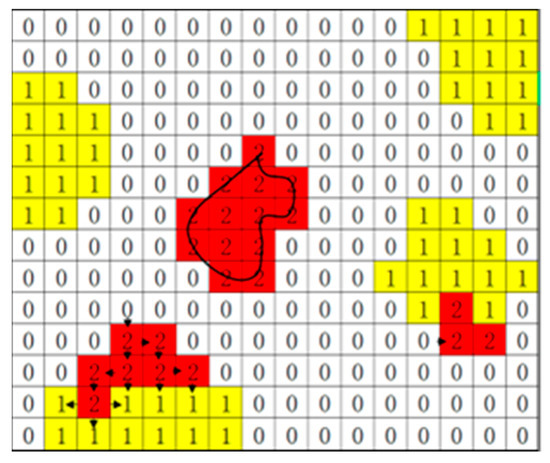
Figure 1.
Candidate droplet identification mechanism.
First, the parameter G was set to mark all cell colors at the gas–liquid interface. If the cell was fully or partially filled with paint liquid, it was given the color yellow (G = 1); if the cell was fully filled with air, it was given the color white (G = 0). The contiguous cells with the tag G = 1 were collected into a uniquely indexed liquid structure where cells were given the color red (G = 2); immediately, the neighbors of the cells were searched. If a cell with G = 1 was found, its color was converted to red (G = 2), and it was added to the liquid structure. The search direction for the first few search steps is indicated by the arrows shown in Figure 1. The search was not stopped until no cells with tag G = 1 could be found. Thus, one isolated paint liquid structure represented by a list of cell indices was obtained. All isolated liquid structures, which represent the candidate paint droplets, can be marked in the calculation domain by the search pattern above.
Whether the candidate droplet was converted into a Lagrangian particle was determined by two physical criteria. Firstly, the droplet volume Vtran could not be larger than the standard volume Vcri, as follows [31]:
where Rcri represents the equivalent sphere radius, which is N times the mesh size ∆x, N being 5 here.
Secondly, the sphericity of the droplet should meet the criteria, which can be defined as follows:
where Rmax is the maximum distance from a point in the liquid structure to the center of mass.
Droplets satisfying the above criteria were removed from the continuous phase of the Eulerian method and then converted into Lagrangian particles. Immediately, the volume fraction function of cells in the domain was updated, namely, , . The volume, mass center, and velocity of the Lagrangian particles are calculated as follows:
2.2.2. Lagrangian Particle Transportation Model
The particles in the atomization flow field follow Newton’s second law. According to force balance, the forces acting on the particle equate to the particle inertia, and can be written as follows [32]:
where mp represents paint particle mass (kg/s), and Fp is the resulting force (N) acting on the particle, in which the drag force of the fluid on the droplet Fdrag, the effect of gravity Fgravitation, and the force due to particle rotation FR were considered, which is shown as follows:
The gravity action per unit mass of the droplet is
The drag force Fdrag was mainly caused by the relative motion of the fluid and the droplet in the flow field. The equation is as follows:
where uq is the velocity of the fluid in the flow field (m/s), is the paint density (kg/m3), is the paint particle diameter (m), and is the relative Reynolds number, which is defined as follows:
The drag coefficient can be expressed as follows:
where , , and are constants for spherical droplets within a certain range of Reynolds number [33].
In the paint atomization process, the additional force FR caused by the particle rotation was a component of its acceleration, which greatly influenced the particle trajectory in the atomization flow field. FR can be written as follows [34]:
where is the angular velocity of droplet rotation (rad/s), and Rp is the vector connecting the origin to the position of the droplet.
2.3. Turbulence Model
The realizable k–ε model of the two-equation turbulence model was applied to simulate the turbulent motion of the gas phase and liquid phase in the atomization process, and the turbulent dissipation rate equation was modified based on the standard k–ε turbulence model [35], resolving the abnormality of the dissipation rate of the cylindrical jet in other k–ε turbulence models. Due to the complex cylindrical jet motion in the air spraying atomization process, it is suitable to describe its turbulent motion with the realizable k–ε model. In recent years, this model has been widely applied in multi-phase flow engineering simulation [22]; therefore, its mathematical expression will not be discussed here.
3. Numerical Approach
3.1. Nozzle Geometry Model and Computational Domain
The 3D model and the sectional view of the air cap of the spray gun (W–71, Anest Iwata Co., LTD, Tokyo, Japan) are shown in Figure 2 and Figure 3, respectively. The center of the air cap is the paint inlet, and the concentric ring with the paint inlet is the central atomizing air inlet. Two auxiliary atomizing air inlets are arranged on both sides of the central atomizing air inlet, and a fan-shaped atomizing air inlet is set on the trumpet mouth on each side of the air cap. The detailed size parameters are outlined in Table 1.
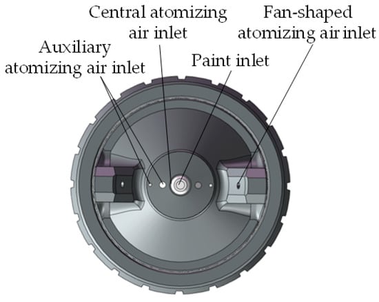
Figure 2.
Three-dimensional model of the air cap.
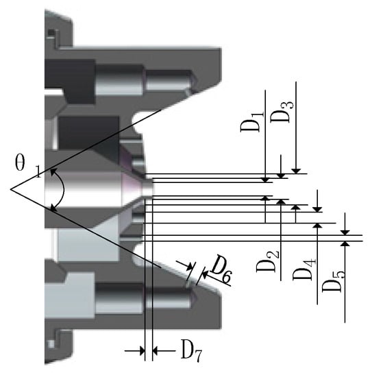
Figure 3.
Sectional view of the air cap.

Table 1.
The parameters of the air cap.
In order to improve the computational efficiency and simplify the geometry model, as is shown in Figure 4, the computational domain was set to a cylinder with a base radius of 12 mm and a height of 50 mm. The adaptive hexcore mesh refinement technique was applied for meshing the computational domain, which controls the global mesh quantity and ensures a better simulation accuracy. Adaptive hexcore mesh refinement in the planes XOZ and YOZ of the computational domain is shown in Figure 5.
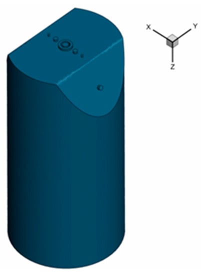
Figure 4.
Computational domain of paint atomization simulation.
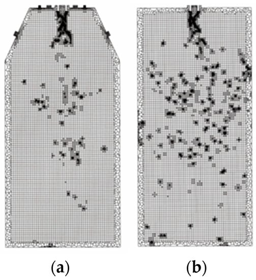
Figure 5.
Adaptive hexcore mesh refinement. (a) Plane XOZ. (b) Plane YOZ.
3.2. Initial Conditions and Solution Algorithms
The paint atomization process includes gas phase and liquid phase atomization, respectively. Accordingly, the gas phase was defined as the primary phase and the liquid phase as the second. The air was chosen for the gas phase and the white primer for the liquid phase. The physical parameters of air and paint were obtained by looking up the data sheet and measuring them with densimeter, viscometer, and surface tensimeter, respectively. The physical parameters of the gas–liquid phase and the corresponding inlet conditions are shown in Table 2.

Table 2.
Gas and liquid physical parameters and corresponding inlet conditions.
The ambient pressure was set as 1 atm, and the acceleration of gravity was set as 9.8 m/s2. The adaptive time step was in use with an initial calculation time step of 1 × 10⁻⁷ s and a total simulation time of 2.5 ms. The numerical simulation was carried out based on the software of ANSYS Fluent 19.0, and the pressure-based coupled algorithm was used to discretize and solve the pressure–velocity coupled equation. The second-order upwind scheme was used for the convective terms in all the flow equations and scalar equations, and the first-order implicit scheme was used for the discretization of the transient terms.
4. Results and Discussion
4.1. Mesh Independence
The three-level adaptive mesh refinement was used for meshing the computational domain. According to the relationship between the spray particle size and the mesh size, five initial sizes of 0.1 mm, 0.2 mm, 0.3 mm, 0.4 mm, and 0.5 mm were selected to carry out atomization simulation. Figure 6 and Figure 7 show the relationship between the initial mesh size and mesh parameters, and the air velocity variation of the spraying flow field under different initial mesh sizes, respectively.
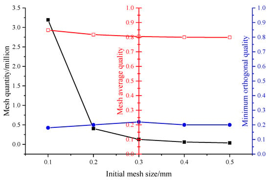
Figure 6.
Parameters of initial mesh with different sizes: Black line: Mesh quantity; Red line: Mesh average quality; Blue line: Minimum orthogonal quality.
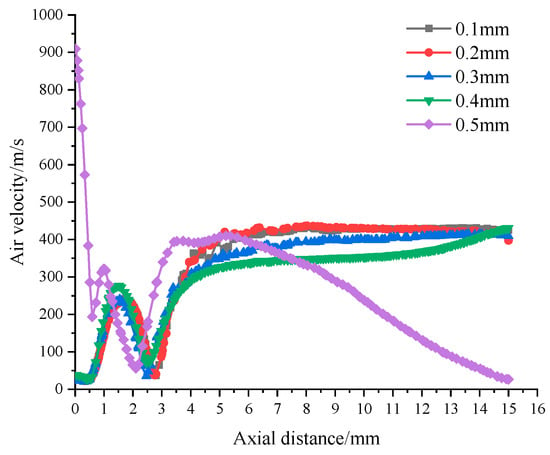
Figure 7.
Air velocity of spray flow field under different initial mesh sizes.
It can be seen in Figure 6 that the number of grids increased with the reduction in the maximum unit length. When the maximum unit length of grids decreased from 0.5 mm to 0.2 mm, the number of grids changed slightly, whereas when the maximum unit length decreased from 0.2 mm to 0.1 mm, the number of grids exploded by a factor of 7.0. The average grid mass also increased with the reduction in cell length, but the increase was small. The average quality of grids increased with the reduction in unit length, but was not obvious, as was the influence of the maximum unit length of grids on the minimum orthogonal quality.
In Figure 7, when initial mesh size was 0.5 mm, the gas velocity of the atomization flow field reached 900 m/s at the inlet, and presented a nearly linear decrease at 5–15 mm away from the nozzle, which is inconsistent with the actual spraying data. That is to say, the initial mesh with a size of 0.5 mm was not sufficient to capture the basic characteristics of the atomization flow field, such as the gas–liquid interaction interface and the overall characteristics of the turbulence field, etc. Other simulation results showed a consistent trend, indicating that the initial mesh with a size less than 0.4 mm can cover the simulation needs of the paint atomization flow field. In the simulation results, the initial meshes with a size of 0.1 mm and 0.2 mm showed the highest curve consistency.
As a result, the value of 0.2 mm was selected as the maximum unit length of initial mesh, which was the best choice for meshing the computational domain of paint atomization simulation, since one can obtain higher mesh quality with a lower mesh quantity.
4.2. Model Credibility Analysis
4.2.1. Spray Film-Forming Experiment
The accuracy of spray film-forming result is an important criterion to measure the effect of air spraying atomization. In order to verify the calculation correctness of the atomization model, the calculated spray flow field parameters were selected as the initial conditions to conduct spray film-forming simulation. Subsequently, the simulation results were compared with the film-forming experimental results.
The spray film-forming experiment was carried out in a closed spray booth. The spraying conditions such as gas–liquid properties, environmental conditions, and spraying parameters were consistent with those of the numerical simulation. During the spraying process, the spray gun was perpendicular to the spraying plane from beginning to end, and the GB–Q235 steel plate (Jingshou Iron & Steel Trading Co., Ltd., Tianjin, China) was sprayed statically. The flow chart of film thickness comparison between numerical simulation and spraying experiment is shown in Figure 8.
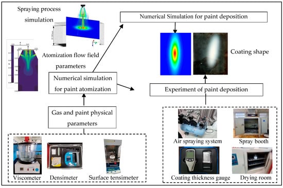
Figure 8.
The flow chart of film thickness comparison between numerical simulation and spraying experiment.
After the paint film was completely dried and cured, the thickness of the elliptic film in the long axis (Y direction) and the short axis (X direction) was measured by a coating thickness gauge. During the measurement process, each measurement point was counted three times, and the average value was calculated as the film thickness of each point. The comparison of paint film thickness obtained by the experiment and the numerical simulation is shown in Figure 9.
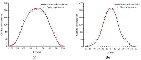
Figure 9.
Comparison of paint film thickness. (a) Paint film thickness distribution along the long axis. (b) Paint film thickness distribution along the short axis.
As is seen from Figure 9, the experimental spraying results of the coating thickness distribution of the plane were consistent with the numerical simulation results in general. However, some errors still appeared as follows: at both sides, the experimental coating thickness was larger than the numerical simulation results, whereas the middle parts showed the opposite trend, which was mainly caused by the leveling property of the liquid paint.
4.2.2. Comparison of Paint Atomization Shape
A high-speed camera was used to capture the shape of the spray flow field, and the measurement system for the paint atomization shape is displayed in Figure 10. The conditions of the atomization experiment and numerical simulation were consistent, and the atomization shapes obtained by measurement and numerical simulation are shown in Figure 11. The results of numerical simulation and experimental measurement were both conical, showing a high degree of similarity. In addition, the spray diffusion range increased gradually with the increase in axial distance. The experimental atomization shape showed a continuous and uniform distribution; by contrast, the numerical simulation results showed a granular distribution, which was mainly caused by the limited resolution of the optical instrument and the over-density of the spray particles.
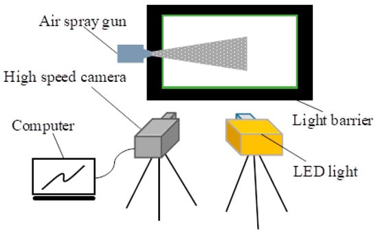
Figure 10.
Paint atomization shape measurement system.

Figure 11.
Atomization shape of air spraying. (a) Experimental measurement. (b) Numerical simulation.
4.2.3. Paint Atomization Process
The accuracy of the atomization model was further verified by checking whether the process of paint liquid atomizing into droplets in the numerical simulation was consistent with the objective facts.
Figure 12 shows the visualization of the paint atomization process at the nozzle in the atomization flow field. In the paint atomization process of air spraying, the paint was broken into liquid micelle droplets from a continuous paint flow affected by the common impact of central atomizing air, auxiliary atomizing air, and fan-shaped atomizing air after the paint was ejected from the nozzle. The atomization process of the paint can be divided into two stages, the primary atomization stage and the secondary atomization stage [25]. The numerical simulation result was subsequently verified.
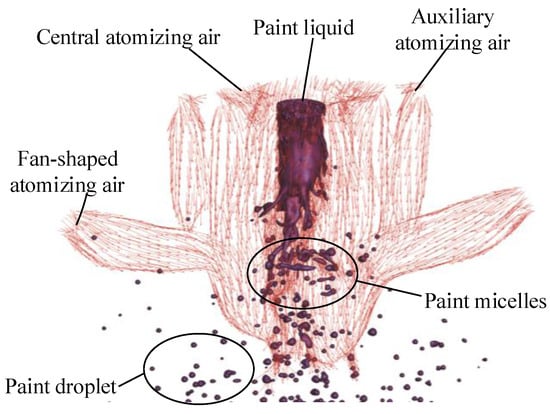
Figure 12.
Paint atomization process.
Six moments ranging from 2.066 ms to 2.118 ms were selected to clearly display the complete process of paint flow from primary atomization to secondary atomization, and the atomization in the flow field was locally amplified. The volume fraction of the paint phase was 10%. The formation process of paint droplets is shown in Figure 13a–c and Figure 14a–d, where Figure 13a is a local enlarged view of Figure 12 with a changed angle, and Figure 14a is a local enlarged view of Figure 13c.
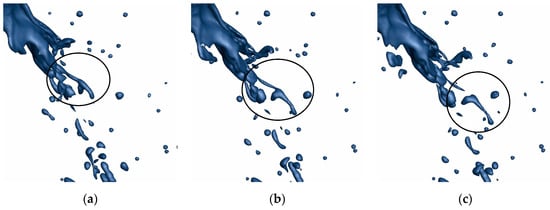
Figure 13.
Formation process of paint micelles: (a) 2.066 ms, (b) 2.077 ms, and (c) 2.084 ms.

Figure 14.
Formation process of paint droplets: (a) 2.084 ms, (b) 2.098 ms, (c) 2.107 ms, and (d) 2.118 ms.
As seen from the figures above, the paint wake flow gradually became thinner and then fell off from the main liquid column of the paint, forming independent micelles under the action of the surrounding air swirl during the spraying period from 2.066 ms to 2.084 ms, which is consistent with the primary atomization theory [36]. Subsequently, the paint micelles began to break into several smaller micelles due to the continuous impact of the high-speed airflow and air swirl. The smaller micelles gradually dispersed with the airflow, and continued to break up under the repeated action of airflow and air swirl, until they formed tiny paint droplets, as is shown in Figure 14, which is consistent with the report of secondary atomization by Fogliati et al. [22].
In summary, the solution accuracy of the atomization model established in this paper was verified by comparing the spraying experimental results with the numerical simulation results. The model can accurately describe the atomization process of air spraying by verifying the atomization shape and atomization process of paint. Namely, the established multi-scale atomization model in this paper is reliable for studying the atomization process of air spraying coatings.
The numerical simulations above were powered by an Intel Xeon(R) Gold 6242 CPU. According to the statistics, a single example takes about 70 h to compute by 60 CPU cores. In contrast, it took about 150 h to simulate the same paint atomization process based on the atomization model established by the Euler–Euler method [25].
5. Conclusions
In this paper, a multi-scale paint atomization model based on hybrid Euler–Lagrange method was established for the paint atomization process of air spraying. The model calculation method consisting of a finite volume method, an adaptive hexcore mesh refinement technique and pressure-based coupled algorithm was established. The simulation results based on the atomization model demonstrated that this model can describe the complete paint atomization process, and the computational effort required was greatly reduced compared with the DNS-like method of the paint atomization process.
In the model verification section, the mesh independence verification showed that the optimal initial mesh size was 0.2 mm. In comparison with the experimental data, the established multi-scale paint atomization model successfully predicted the atomization flow field parameters, the paint atomization shapes, and the process of changing from paint to liquid droplets. The solution of the model and the agreement with the actual paint atomization phenomenon were both accurate and acceptable.
The multi-scale paint atomization model is a powerful method to study the influencing factors of the paint atomization process in air spraying. In the future, the influence of spraying parameters such as the air atomization pressure, the paint flow rate, and the paint properties on the atomization process will be further studied based on the multi-scale paint atomization model.
Author Contributions
Conceptualization, methodology, validation, and formal analysis, S.C.; software, Y.C.; investigation, J.J.; resources and data curation, S.C. and Y.C.; writing—original draft preparation, S.C. and Z.W.; writing—review and editing, S.C. and Z.W.; visualization, J.L.; supervision, W.H.; project administration, S.C.; funding acquisition, Y.C., J.J. and W.H. All authors have read and agreed to the published version of the manuscript.
Funding
This project is supported by the National Natural Science Foundation of China (Grant No. 51475469) and the Science and Technology Research Program of Chongqing Municipal Education Commission (Grant No. KJZD-M201912901, KJZD-M202212901, and KJZD-M202212903).
Conflicts of Interest
All of the authors declare that they have no known competing financial interests or personal relationships that could have appeared to influence the work reported in this paper.
References
- Liu, Y.J.; Zi, B.; Wang, Z.Y.; Wei, Y.; Lei, Z. Research Progress and Trend of Key Technology of Intelligent Spraying Robot. J. Mech. Eng. 2022, 58, 53–74. [Google Scholar]
- Ning, Y.; Meng, M. Analysis and Prospect of Spraying Robot Path Planning Method. Sci. Technol. Eng. 2019, 19, 19–27. [Google Scholar]
- Guan, L.W.; Chen, L. Trajectory Planning Method Based on Transitional Segment Optimization of Spray Painting Robot on Complex-free Surface. Ind. Robot 2019, 46, 31–43. [Google Scholar] [CrossRef]
- Zhang, S.Z.; Mao, W.; Zhen, J.B. Research Progress of Coating Thickness Distribution Model by Electrostatic Spraying. Surf. Tech. 2019, 48, 291–297. [Google Scholar]
- Daniel, G.; Stefan, J.; Raad, S.; Sandgren, N.; Edelvik, F.; Carlson, J.S.; Lennartson, B. Robot Spray Painting Trajectory Optimization. In Proceedings of the 2020 IEEE 16th International Conference on Automation Science and Engineering, Hong Kong, China, 20–21 August 2020. [Google Scholar]
- Chen, Y.; Chen, W.Z.; Li, B.; Zhang, G.; Zhang, W. Paint Thickness Simulation for Painting Robot Trajectory Planning: A Review. Ind. Robot Int. J. 2017, 44, 629–638. [Google Scholar] [CrossRef]
- Chen, W.; Chen, Y.; Wang, S.; Han, Z.; Lu, M.; Chen, S. Simulation of a Painting Arc Connecting Surface by Moving the Nozzle Based on a Sliding Mesh Model. Coatings 2022, 12, 1603. [Google Scholar] [CrossRef]
- Chen, S.M.; Chen, W.Z.; Chen, Y.; Jiang, J.; Wu, Z.; Zhou, S. Research on Film-Forming Characteristics and Mechanism of Painting V-Shaped Surfaces. Coatings 2022, 12, 658. [Google Scholar] [CrossRef]
- Chen, W.Z.; Chen, Y.; Zhang, W.M.; He, S.; Li, B.; Jiang, J. Paint Thickness Simulation for Robotic Painting of Curved Surfaces Based on Euler-Euler Approach. J. Braz. Soc. Mech. Sci. 2019, 41, 1–9. [Google Scholar] [CrossRef]
- Ye, Q.Y.; Domnick, J. Analysis of Droplet Impingement of Different Atomizers used in Spray Coating Processes. J. Coat. Technol. Res. 2017, 14, 467–476. [Google Scholar] [CrossRef]
- Ye, Q.Y.; Pulli, K. Numerical and Experimental Investigation on the Spray Coating Process using a Pneumatic Atomizer: Influences of Operating Conditions and Target Geometries. Coatings 2017, 7, 13. [Google Scholar] [CrossRef]
- Wang, Y.N.; Xie, X.P.; Lu, X.H. Design of a Double-Nozzle Air Spray Gun and Numerical Research in the Interference Spray Flow Field. Coatings 2020, 10, 475. [Google Scholar] [CrossRef]
- Xie, X.P.; Wang, Y.N. Research on Distribution Properties of Coating Film Thickness from Air Spraying Gun-Based on Numerical Simulation. Coatings 2019, 9, 721. [Google Scholar] [CrossRef]
- Liu, C.B.; Zhou, L.X.; Lei, F.P. Overview on Numerical Simulations of Primary Atomization. J. Rocket Propul. 2014, 40, 10–17. [Google Scholar]
- Maziar, S.; Mahmoudzadeh, S. Numerical Investigation of Spray Characteristics of an Air-Blast Atomizer with Dynamic Mesh. Aerosp. Sci. Technol. 2017, 70, 351–358. [Google Scholar]
- Beji, T.; Zadeh, S.E.; Maragkos, G.; Merci, B. Influence of the Particle Injection Rate, Droplet Size Distribution and Volume Flux Angular Distribution on the Results and Computational Time of Water Spray CFD Simulations. Fire Safety J. 2017, 91, 586–595. [Google Scholar] [CrossRef]
- Sabty-Daily, R.A.; Harris, P.A.; Hinds, W.C.; Froines, J.R. Size Distribution and Speciation of Chromium in Paint Spray Aerosol at an Aerospace Facility. Ann. Occup. Hyg. 2005, 49, 47–59. [Google Scholar]
- Pourmousa, A.; Mostaghimi, J.; Abedini, A.; Chandra, S. Particle Size Distribution in a Wire-Arc Spraying System. J. Therm. Spray Technol. 2005, 14, 502–510. [Google Scholar] [CrossRef]
- Pendar, M.R.; Pascoa, J.C. Atomization and Spray Characteristics around an ERBS Using Various Operational Models and Conditions: Numerical Investigation. Int. J. Heat. Mass. Transf. 2020, 161, 120243. [Google Scholar] [CrossRef]
- Li, W.T.; Qian, L.J.; Song, S.B.; Zhong, X. Numerical Study on the Influence of Shaping Air Holes on Atomization Performance in Pneumatic Atomizers. Coatings 2019, 9, 410. [Google Scholar] [CrossRef]
- Andersson, B.; Jakobsson, S.; Mark, A.; Edelvik, F.; Davidson, L.; Carlson, J.S. A Modified TAB Model for Simulation of Atomization in Rotary Bell Spray Painting. J. Mech. Eng. Autom. 2013, 3, 54–61. [Google Scholar]
- Fogliati, M.; Fontana, D.; Garbero, M.; Vanni, M.; Baldi, G.; Donde, R. CFD Simulation of Paint Deposition in an Air Spray Process. J. Coat. Technol. Res. 2006, 3, 117–125. [Google Scholar] [CrossRef]
- Wang, Z.Y.; Li, Y.K.; Huang, B.; Gao, D. Numerical Investigation on the Influence of Surface Tension and Viscous Force on the Bubble Dynamics with a CLSVOF Method. J. Mech. Sci. Technol. 2016, 30, 2547–2556. [Google Scholar] [CrossRef]
- Kumar, S.N.; Premachandran, B. A Coupled Level Set and Volume of Fluid Method on Unstructured Grids for the Direct Numerical Simulations of Two-phase Flows including Phase Change. Int. J. Heat. Mass. Tran. 2018, 122, 182–203. [Google Scholar] [CrossRef]
- Chen, Y.; Chen, S.; Chen, W.; Hu, J.; Jiang, J. An Atomization Model of Air Spraying Using the Volume-of-Fluid Method and Large Eddy Simulation. Coatings 2021, 11, 1400. [Google Scholar] [CrossRef]
- Chen, X.D.; Yang, V. Recent advances in Physical Understanding and Quantitative Prediction of Impinging-jet Dynamics and Atomization. Chin. J. Aeronaut. 2019, 32, 45–57. [Google Scholar] [CrossRef]
- Li, X.Y.; Soteriou, M.C. Prediction of High Density-Ratio Liquid Jet Atomization in Crossflow Using High Fidelity Simulations on HPC. In Proceedings of the 50th AIAA Aerospace Sciences Meeting Including the New Horizons Forum and Aerospace Exposition, Nashville, TN, USA, 9–12 January 2012. [Google Scholar]
- Zuzio, D.; Estivalèzes, J.L.; DiPierro, B. An Improved Multi-Scale Eulerian—Lagrangian Method for Simulation of Atomization Process. Comput. Fluids 2018, 176, 285–301. [Google Scholar] [CrossRef]
- Brackbill, J.; Kothe, D.B.; Zemach, C. A continuum method for modeling surface tension. J. Comput. Phys. 1992, 100, 335–354. [Google Scholar] [CrossRef]
- Herrmann, M. A Parallel Eulerian Interface Tracking/Lagrangian Point Particle Multi-Scale Coupling Procedure. J. Comput. Phys. 2010, 229, 745–759. [Google Scholar] [CrossRef]
- Lei, Z.; Jun, X.; Shinjo, J.J.; Cairns, A.; Cruff, L.; Blaxill, H. Development of a Hybrid Multi-Scale Simulation Approach for Spray Processes. Proc. Inst. Mech. Eng. Part D J. Autom. Eng. 2015, 230. [Google Scholar] [CrossRef]
- Xiao, Y.H.; Liu, W.B.; Liu, D.Q. Simulation of Liquid Atomization in Cyclone Atomizer Based on VOF-DPM Coupling Model. In Proceedings of the 2019 2nd World Conference on Mechanical Engineering and Intelligent Manufacturing (WCMEIM 2019), Shanghai University, Shanghai, China, 22–24 November 2019. [Google Scholar]
- Morsi, S.A.; Alexander, A.J. An Investigation of Particle Trajectories in Two-Phase Flow Systems. J. Fluid Mech. 1972, 55, 193–208. [Google Scholar] [CrossRef]
- Yang, L.N.; Guo, Z.L.; Cai, P.; Wang, B. Study of the Magnitude Analysis of Coriolis Force in Hydrocyclone. Fluid Mach. 2015, 43, 21–27. [Google Scholar]
- Zhao, F.; Zhang, Y.L.; Zhu, R.; Wang, H. Turbulence Model in Supersonic Jet Flow Field. J. Univ. Sci. Technol. B. 2014, 36, 366–372. [Google Scholar]
- Christophe, D. On the experimental investigation on primary atomization of liquid streams. Exp. Fluids 2008, 45, 371–422. [Google Scholar]
Publisher’s Note: MDPI stays neutral with regard to jurisdictional claims in published maps and institutional affiliations. |
© 2022 by the authors. Licensee MDPI, Basel, Switzerland. This article is an open access article distributed under the terms and conditions of the Creative Commons Attribution (CC BY) license (https://creativecommons.org/licenses/by/4.0/).