Article

Distribution Characteristics and Cause Analysis of Casing Deformation during Hydraulic Fracturing of Shale Gas Wells

1
The College of Petroleum, China University of Petroleum (Beijing) at Karamay, Xinjiang 834000, China
2
Southern Sichuan Gas District, PetroChina Southwest Oil & Gas Field Company, Luzhou 646000, China
3
Sichuan Baoshihua Xinsheng Oil & Gas Operation Co., Ltd., Chengdu 610041, China
4
The College of Petroleum Engineering, China University of Petroleum (Beijing), Beijing 102249, China
5
Engineering Technology Research Institute, Xinjiang Oil Field Company, Karamay 834000, China
*
Author to whom correspondence should be addressed.
Processes 2022, 10(11), 2421; https://doi.org/10.3390/pr10112421
Submission received: 4 October 2022 / Revised: 4 November 2022 / Accepted: 14 November 2022 / Published: 16 November 2022

Abstract

:
The distribution characteristics and causes of casing deformation during hydraulic fracturing were investigated. Finite element models of a casing–cement sheath-formation assembly, considering a multi-stage fracturing process, were established. The axial displacement law of formation during multi-stage fracturing was analyzed. Furthermore, considering the existence of faults, the mechanism of casing deformation caused by fault slippage due to axial displacement was analyzed. Finally, the influence of fault parameters, as well as the casing’s geometry and mechanical parameters, on casing deformation were clarified. The results show that the casing deformation point is densely located near landing point A and sparsely located near toe point C. The entry of high-pressure fracturing fluid into the formation would reduce the effective stress of the formation and could even change it from compression to tension, which would mean that the formation in the fractured section would be stretched in the axial direction, squeezing the formation in the non-fractured area and causing axial displacement; the closer the formation is to point A, the greater the displacement. The change in casing deformation can be divided into three stages. In the first, the casing deformation is zero when the fracturing section is far from the fault. In the second, the casing deformation increases significantly when the fracturing section is close to the fault. In the third, the casing deformation increases slowly when the fracturing section deviates from the fault. The closer the fault is to landing point A, the greater the length, the smaller the dip angle, and the larger the casing deformation, and vice versa. In contrast, increasing casing wall thickness and steel grade has little effect on relieving the casing deformation.

1. Introduction

Shale gas reservoirs are characterized by low porosity and permeability; as a result, conventional development methods cannot be used for commercial gas production. Therefore, hydraulic fracturing technology is required to achieve stimulated reservoir volume (SRV) and to form channels for oil and gas. However, this method can seriously threaten the integrity of the casing, reduce the casing’s inner diameter and increase the curvature, which would lead to the plug not being set in the specified position, which can affect the fracturing effect and increase the operating cost and difficulty [1,2,3].
The commissioning of the Wei-201 well in the Sichuan shale gas block in China in 2010 marked the beginning of commercial development in the China shale gas industry. However, casing deformation occurred in the same year, and the proportion of casing deformation wells remained around 30% for a long time. Because the casing is an integral part of the wellbore barrier, it has been the focus of extensive research. At the primary stage, this research mainly addresses the causes of casing deformation in conventional oil and gas wells; the deformation of the casing in shale gas wells was thought to be primarily influenced by engineering factors such as cementing quality [4,5], bending stress [6], temperature variation [7], and annulus bound fluid [8]. With the application of MIT multi-arm caliper logging, micro-seismics, and ant attribute volume imaging logging in shale gas wells, the researchers further determined the correlation between the casing’s deformation shape and position and the fault–lithological interface. The formation of a complex network enables the casing to withstand shear loads, resulting in casing deformation. Li et al. investigated whether the fracturing operation would result in the high-angle slippage of the formation and whether the casing would produce bending deformation in the up or down direction [9]. Yin et al. clarified the shear deformation mechanism of the casing and investigated the leading printing and multi-arm caliper logging results [10]. Chen et al. analyzed the development of formation fractures at the deformation position of the casing. They found that the deformation point was significantly related to the development of the fracture. Li et al. clarified the relationship between the lithologic interface and casing deformation by comparing geological logging results and casing deformation positions [11]. Yan et al. believed that the casing deformation was mainly caused by in situ stress changes caused by earthquakes [12]. Based on the structural characteristics and mechanical properties of the shale rock, li et al. believed that the casing stress would increase rapidly when the shale expanded without stress-release conditions and that intensive perforation would prevent casing deformation [13]. It is usually thought that the deformation position of the casing coincides strongly with the lithological interface and the fault [14,15,16]. The fault slippage mainly causes the deformation of the casing, and the shape of the deformation is particular to the shear deformation [17,18,19,20,21,22]. The reason for the fault slippage induced by multi-stage fracturing is that the fracturing fluid enters the fault through a specific path, and the pore pressure inside the fault increases until it is activated [23,24,25,26].
The above research has provided essential insights clarifying the deformation mechanism of the casing. However, more analysis needs to be done on the site distribution characteristics and causes of the casing deformation phenomenon. In the following, we outline our research method. In this paper, the casing deformation wells were taken as the research object during multi-stage fracturing in the Sichuan Basin, China. First, the distribution characteristics of the casing deformation positions were analyzed. On this basis, the fluid–solid coupling numerical calculation model of the casing–cement sheath-formation assembly under a multi-stage fracturing process was established, and the variation law of formation axial displacement during the multi-stage fracturing process was analyzed. Finally, considering that casing deformation is closely related to faults, based on the aforementioned fluid–solid coupling calculation model, a fluid–solid coupling numerical calculation model of casing–cement sheath-formation assembly considering fault slippage was established, and the influencing factors of casing deformation were clarified.

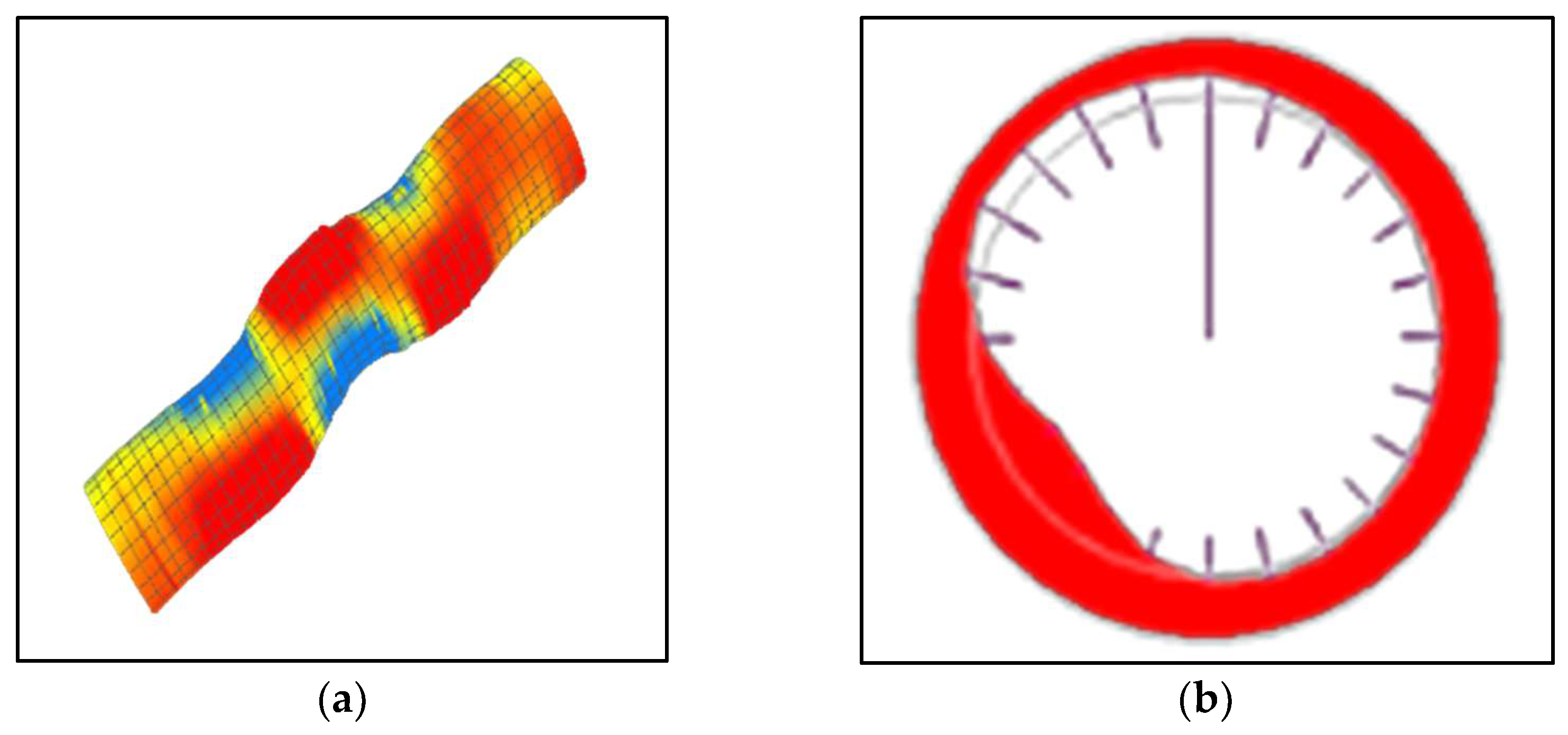
2. Characteristics of Casing Deformation

Shale gas development in China is primarily concentrated in the Sichuan Basin. The large-scale commercial development blocks currently include the Changning–Weiyuan block, Fuling block, and Weirong block. However, a severe casing deformation phenomenon was found to have occurred in the blocks mentioned above during hydraulic fracturing. The Weirong shale gas block is an example; the proportions of casing deformation wells in 2018, 2019, 2020, and 2021 are 83.3%, 50%, 36.2%, and 53.8%, respectively. Due to the deformation of the casing, some shale gas wells must be milled, and, in serious cases, the entire horizontal section cannot be fractured. The casing deformation wells in the Weirong block primarily involve shear deformation (89.0%), with only a few wells exhibiting extrusion deformation (11.0%). Figure 1 shows the typical deformation morphology of the casing.
Based on the multi-arm caliper logging results, this study also offers statistics on the casing deformation of some shale gas wells, and the results are shown in Figure 2.
It is necessary to define casing deformation. If the original diameter of the casing is D, and the diameter measured by the multi-arm caliper logging tool is D1, the casing deformation is ΔD = D − D1. As illustrated in Figure 2, abscissa abbreviations represent shale gas wells in the Weirong Shale Gas Block in Sichuan Basin, China, where the deformation is predominantly between 9.12 and 38.62 mm, and the maximum deviation between the casing and the bridge is only 8.9 mm. This means that the deformation would block the bridge. More than one casing deformation point exists in some shale gas wells, which can thus block the bridge more than once.
Additional statistics on the position distribution of the deformation points are given. In this study, the landing point in the horizontal section, i.e., the point where the inclination angle is 0°, is defined as point A, the mid-position of the horizontal section is point B, and the final position of the horizontal section is point C. The distribution of the positions of the deformation points is computed, and the statistical results are presented in Figure 3.
Figure 3 shows the distribution features of the casing deformation points during the multi-stage fracturing process. Compared to the statistical results of casing deformation, the casing deformation positions are easier to count. Besides the multi-arm caliper logging method, printing and the assessment of bridge blockage can also be used to determine if the casing is deformed. The deformation points of the casing are mainly located near point A (less than 400 m), comprising 46.5%; the central section (500~800 m) comprises 43.2%, and only14.9% are found near point C (over 1000 m). These statistics are similar to those of Tong. et al. [27] and Zhang. et al. [28], whose studies on the casing deformation points in the Changning–Weiyuan block in China, show a growing trend towards point A of the horizontal wells. However, the root cause of this engineering phenomenon is not clear.
This study focuses on the distribution characteristics and causes of casing deformation during the multi-stage fracturing process. In contrast to previous studies, the present study establishes a cement–casing sheath-formation assembly process that considers the multi-stage fracturing process. The mechanism by which the axial displacement of the formation activates the fault during the multi-stage fracturing process was studied, and the effects of the fault and the geometric and mechanical parameters of the casing on the deformation of the casing were clarified.

3. Casing Deformation Finite Element Model

3.1. Basic Data

We take a shale gas well in Weiyuan–Changning in the Sichuan Basin in China as an example. The vertical depth of the well is 2720 m, and the horizontal section is 1150 m long and has 23 fracturing stages, each of which is 50 m in length. Each step of the fracturing operation is divided into two phases: liquid injection and flow-back, and the corresponding times are 3 h and 18 h, respectively. The product casing is class P110 with an elasticity limit of 758 MPa, an outer diameter of 139.7 mm, and a wall thickness of 10.54 mm. The maximum, minimum, and vertical in situ stresses are 62, 55, and 68 MPa, respectively. The initial formation pressure is 35.4 MPa. The ant attribute logging results indicate that there are faults at the landing points of the heel, the middle, and the toes of the horizontal section, while the casing deformation location and the fault show a high degree of overlap; that is, the wellbore passes through the fault. However, casing deformation was only detected near the heel (3279 m) and the middle of the horizontal section (3802 m), as shown in Figure 4.

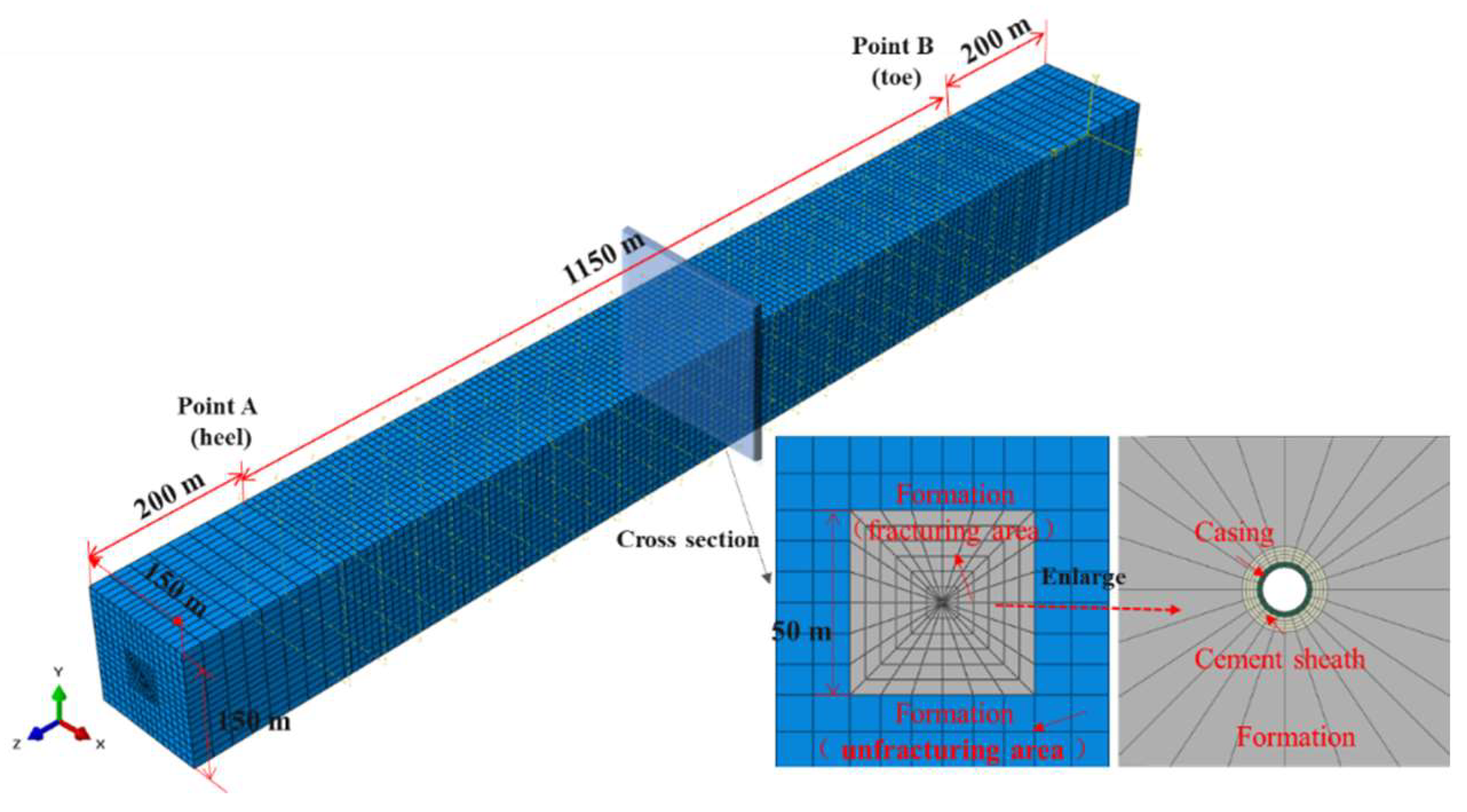
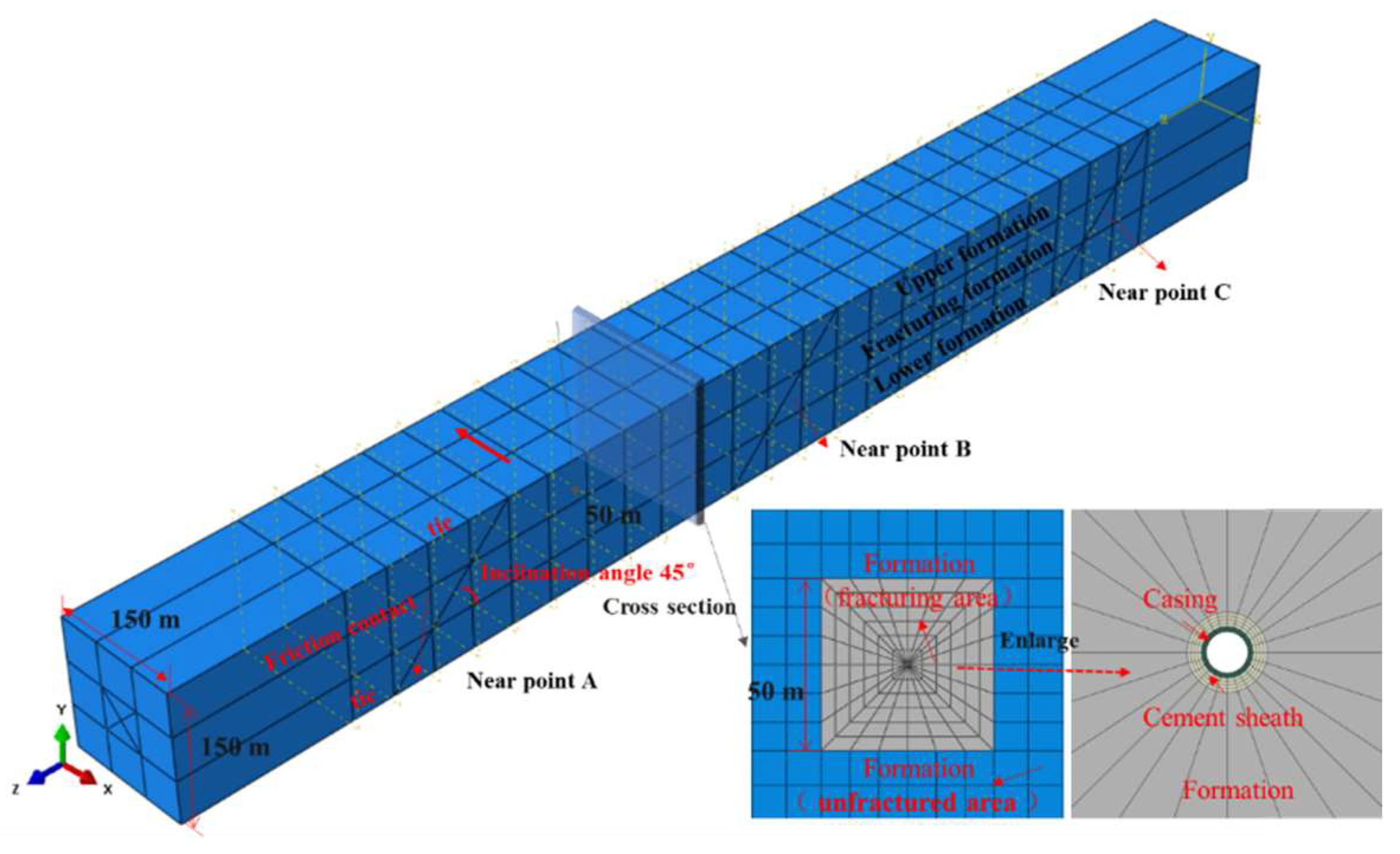
3.2. Finite Element Model

The calculation model for the horizontal well consists of three parts: the casing, the cement sheath, and the formation. As the fracturing operation will form a network of artificial fractures in the formation near the well, and a single-stage fracture network can be up to 250 m long, 50 m wide, and 100 m high, causing changes to the formation pressure and mechanical parameters, according to the Saint-Venant theorem, the influence of formation parameters far from the casing on the stress of the casing can be ignored. Therefore, the numerical model only considers changes in formation pressure and mechanical parameters in the vicinity of the well. The formation is further divided into two parts, one being the fracture zone near the casing; the fracturing process is simulated by modifying the pore pressure and the mechanical parameters of the rock in that area. The other is the un-fractured area far away from the casing; the mechanical parameters of this part of the rock remain unchanged.
Figure 5 shows the 3D numerical calculation model and the model section; the model is 1550 m long, 150 m wide, and 150 m high. The simulation area is 1150 m long, which corresponds to the size of the horizontal section. The numerical model is extended by 200 m at the heel and toe positions to eliminate the influence of the model boundary effect. The formation in the fracture zone is 50 m long, 50 m wide, and 50 m high, and the lateral length is more than ten times the size of the borehole. The purpose of this model is to analyze the law of the formation of axial displacement during multi-stage fracturing.
Furthermore, to analyze the faults’ effects on the deformation of the casing, we used the above model for calculating the axial displacement of the formation, combined with the fault distribution characteristics in Figure 4. The angle between the fault and the minimum in situ stress (Z direction) is set to 45°, and the fault stroke is parallel to the direction of the maximum in situ stress (X direction). On this basis, a calculation model for the fluid–solid coupling of the casing–cement sheath-formation assembly, taking into account the existence of faults, is established, as shown in Figure 6.
The formation is first divided into two parts in the modeling process, the front, and the back. Contact between the upper formation and the lower formation is mandatory. In the formation of fracturing, the divided planes must be in a relationship of friction contact to simulate the fault. The coefficient of friction between the defective planes is set to 0.3. To compare the influences of faults in the middle of the horizontal section and at the tip of the heel on the deformation of the casing, the casing deformations were further analyzed when the faults were located at 3802 m (near mid-point B) and 4430 m (near the end point C). The specific setting method is the same as the fault-setting method at landing point A.

3.3. Material Parameters

In terms of material settings, the casing is set as an ideal elastic–plastic material; this involves the parameters of Young’s modulus, Poisson’s ratio, and the yield stress. This study does not consider the cement sheath’s failure; hence, the cement sheath is simplified to an ideal elastic material to increase the convergence of the numerical calculation model, which involves the parameters of Young’s modulus, Poisson’s ratio, permeability, and porosity. The formation is set in the same way as the cement sheath, and the parameters are Young’s modulus, Poisson’s ratio, permeability, and porosity. Specific parameters are presented in Table 1.
Considering that high-pressure fracturing fluid breaks the formation to form artificial fracture networks during multi-stage fracturing, the elastic modulus of shale rock decreases during this process; this necessitates using a field variable definition function to set the elastic modulus of the formation. In this study, Young’s modulus of the formation after fracturing is taken as 65% of that before fracturing. Specific parameters are shown in Table 1.

3.4. Boundary Condition and Load Settings

Combined with the practice of multi-stage fracturing, the steps involved in the numerical model are the in situ stress balance analysis and the fluid–solid coupling analysis. The in situ stress balance analysis step is mainly intended to balance the formation of skeletal stress and the formation of pore pressure prior to fracturing. A total of 23 fracturing steps were performed in this well, and each fracturing involved two stages: liquid injection and flow-back. As a result, there were 46 stages in the fluid–solid coupling analysis in the model. Based on engineering practice, the time required for the liquid injection analysis was 3 h, and the flow-back analysis time was 18 h.
When establishing boundary conditions, the outer boundary of the formation was constrained by vertical displacement, and the interstitial pressure boundary was adjusted to be equal to the original formation pressure.
When setting the load, the casing pressure during liquid injection was defined as the sum of the surface pump pressure (95 MPa) and the hydrostatic column pressure (27.2 MPa), which was 122.2 MPa, and the casing pressure during flow-back was defined as the sum of the wellhead backpressure (40 MPa) and the hydrostatic column pressure (27.2 MPa), which was 67.2 MPa. In situ stress should act on the formation. The X, Y, and Z directions in Fig. 2 correspond to the horizontal maximum, vertical, and horizontal minimum in situ stresses, respectively.

3.5. Meshing Method

Under the meshing method, the casing, the cement sheath, and the formation mesh structures were equally divided in the axial and radial directions. The grid elements of the casing, the cement sheath, and the formation were C3D8R, C3D8P, and C3D8P, respectively.
As shown in Figure 7, the first stage of the fracturing process concerns determining the formation parameters in the fracturing area. As mentioned above, each fracturing simulation step includes two analysis steps: fluid injection and flow-back. In the fluid injection analysis step, the fracturing fluid enters the fracturing area and causes an increase in formation pressure, and the initial formation pressure in the fracture zone is equal to the initial formation pressure cited above. After the liquid was injected, the well rapidly closed. The fracturing area in the adjacent borehole was connected to the inner wall of the casing through the puncture hole; when the pressure gradient of the fracture zone at a distance from the well is not taken into consideration, the formation pressure in the fracturing area is equal to the pressure in the liquid column of the inner wall of the casing. The liquid column pressure equals the sum of the column hydrostatic pressure and wellhead backpressure.

4. Analysis of Finite Element Method Results

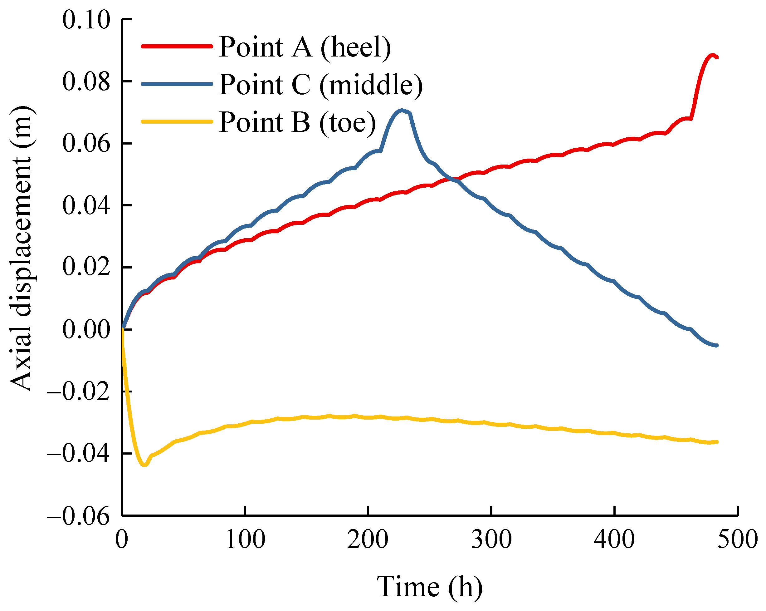
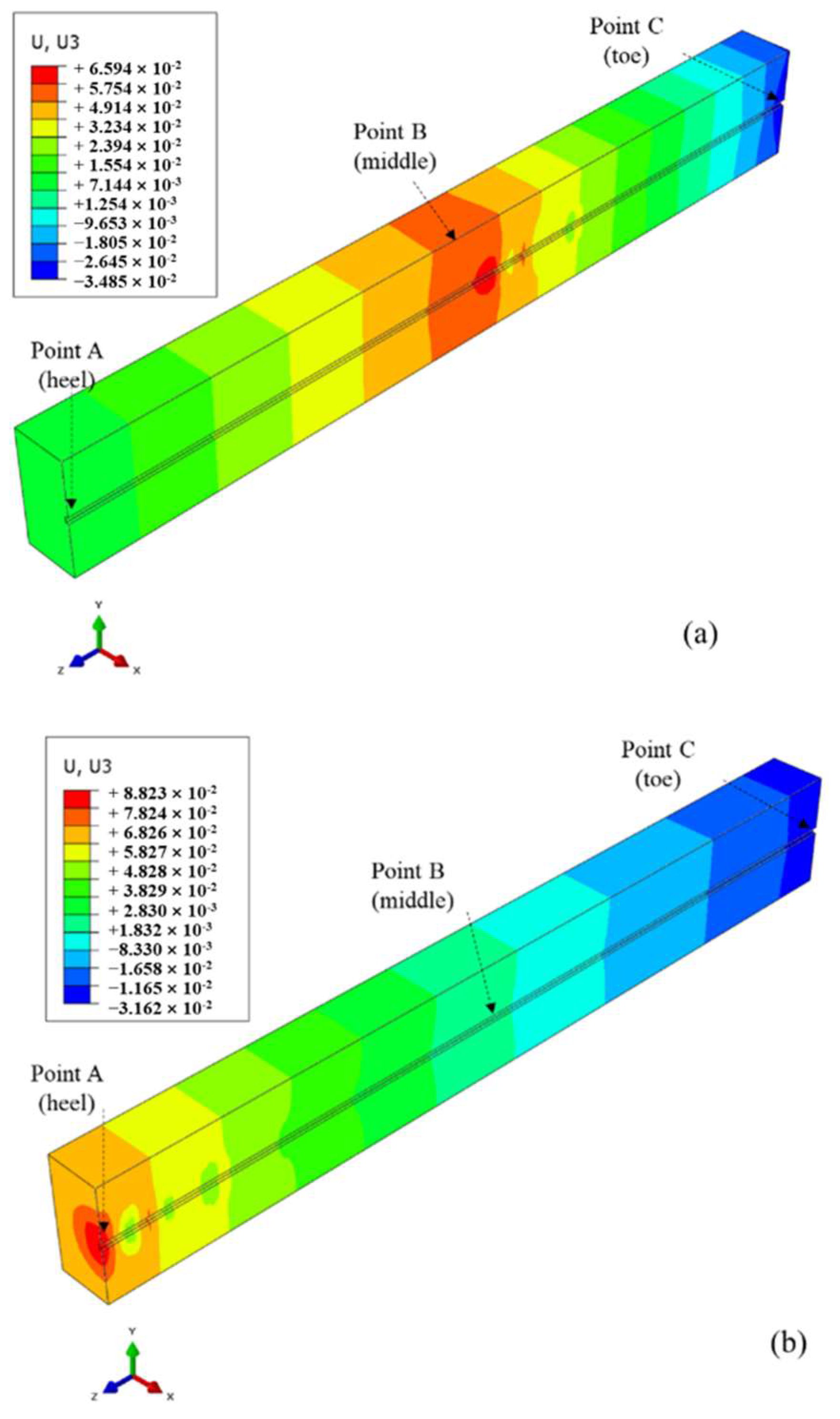
4.1. Formation Axial Displacement

After the high-pressure fracturing fluid enters the formation, the effective stress of the formation will be reduced or may even be modified from compression to tension, causing an axial tensile effect, whereby the fractured formation compresses the non-fractured formation. To analyze the influence of the compression of the formation on its displacement during fracturing, the formations at point A, point B, and point C are here analyzed in order to determine the law of the variation of axial displacement along the wellbore. The analysis results are shown in Figure 8 and Figure 9.
The positive and negative values in Figure 8 and Figure 9 indicate that the formations caused movements in the positive and negative directions of the Z-axis. The axial displacement of point A increased linearly as the fracture stage increased and then increased rapidly when the fracture reached point A. The displacement of the formation at the end of the 23rd fracture stage was 0.088 m. The axial displacement of point B in the middle of the horizontal section showed a tendency to increase first and then decrease; the reason for this is that the subsequent fracturing operation had a reverse extrusion effect, which allowed the formation to progressively return to the initial position; the displacement was negative at point C, indicating negative movement along the Z axis.
The effect of the initial Young’s modulus of the formation on the displacement of the formation at point A at the heel was analyzed next. Keeping other parameters unchanged, the initial Young’s modulus was defined as 20, 30, and 40 GPa, respectively. The results are shown in Figure 10.
As seen in Figure 10, the smaller the initial Young’s modulus of the formation, the weaker the degree of axial compression. The main reason is that the smaller Young’s modulus, the stronger its deformation ability. The extrusion effect generated during fracturing at a distance from point A can be absorbed by the formation.
As discussed above, the formation near the well produced a tensile effect along the well axis because of the influence of high-pressure fracturing fluid on the multi-stage fracturing process, which was not enough to distort the casing. However, it should be noted that recent field research and theoretical studies have demonstrated that the casing deformation is related to the fault. As shown in Figure 11, axial displacement of the formation along the wellbore will generate a shear displacement component along the fault plane when the wellbore crosses the fault, which may activate the fault and lead to casing deformation.

4.2. Casing Shear Deformation Mechanism Caused by Hydraulic Fracturing

Based on the formation displacement accumulation calculation model, a casing–cement sheath-formation assembly process with faults was established (as shown in Figure 6). The casing deformation was compared and analyzed for when the fault was located at 3279 m (near point A), 3802 m (near middle point B), and 4430 m (near point C). The calculation results are shown in Figure 12.
Casing deformation is defined as the difference between the original inner diameter and the deformed inner diameter, as shown in Figure 12; the change in casing deformation during multi-stage fracturing can be divided into three stages: In the first, the deformation of the casing is zero when the fracture section is far from the fault. In the second, the deformation of the casing increases significantly when the fracture section is in the vicinity of the fault. In the third, the casing deformation increases slowly when the fracture section departs from the fault. Taking a case wherein the fault was located near point A, for example, the deformation of the casing was zero during the first 15 stages, 2.6 mm in the 18th stage, and 10.8 mm in the 21st stage. The deformation law at 3802 m also showed a similar trend. The main reason is that cumulative displacement occurred in the axial direction of the wellbore during fracturing. Due to the existence of a fault, the axial displacement showed a shear displacement component along the fault plane, resulting in the shear deformation of the casing.
Meanwhile, the casing deformations at 3279 m and 3802 m were 10.8 mm and 8.6 mm, respectively. It can be seen that the closer the fracture section was to the heel, the larger the deformation of the casing and the greater the risk of the bridge plug being blocked. Further sensitivity analyses of factors affecting casing deformation have also been carried out.

4.3. Sensitivity Analysis

In this study, a sensitivity analysis method was used to control the variables; we only changed one parameter, and the results of other parameters in the model remained unchanged to clarify the impact of a single parameter on casing deformation.
Casing wall thickness. Increasing the casing wall thickness led to an increase in internal pressure and external extrusion strength. Still, the influence of the casing wall’s thickness on the shear strength required further analysis. We took the casing at 3279 m (near point A) in the above model as the analysis subject. The wall thicknesses of the casing were fixed to 9.17, 10.54, and 12.7 mm, respectively. The calculation results are presented in Figure 13.
Although increasing the casing wall’s thickness was conducive to improving its shear resistance, its effect was still far weaker than the shear load acting on the casing. Therefore, increasing the casing wall’s thickness was ineffective in alleviating casing deformation.
As seen in Figure 13, the increase in casing wall thickness had no significant effect on the attenuation of casing deformation, which corresponds with the findings of field engineering. Han et al. [12] reported this phenomenon, believing that formation slippage was part of movement control rather than load control. Although increasing the thickness of the casing wall improved the shear resistance of the casing, its effect was still much weaker than the shear load acting on the casing.
Casing steel grade. The casing in the preceding case was P110. Currently, the steel grade of the casing in some shale gas wells is type TP140V, and the elasticity limit of the respective material can reach above 1000 MPa. The yield strength of the casing was set to 700 MPa, 900 MPa, 1100 MPa, and 1300 MPa, and the deformation of the casing under various elasticity limits was analyzed. The calculation results are presented in Figure 14.
As shown in Figure 14, the steel grades required to alleviate the shearing effects of the casing were negligible; in the first 14 stages of fracture, the corresponding deformation in the casing with various elastic limits was close to 0 mm. After the 20th fracturing stage, the deformations of the casing at elastic limits of 700 MPa and 1300 MPa were 10.6 mm and 9.2 mm, respectively, with a reduction of just 13.2%. It can be considered that increasing the casing wall thickness and steel grade has little impact on mitigating casing deformation, and preventing casing deformation by increasing casing wall thickness and steel grade is not the best approach.
Fault length. The casing shear deformation was significantly affected by faults, and the parameters related to certain faults, such as the length and inclination angle, significantly impacted its stability. According to the above model, the inclination angle was fixed at 45°, and the influences of various fracture lengths on the deformation of the casing could be obtained by modifying the size of the fracturing zone. The calculation results are presented in Figure 15.
Figure 15 shows that the fault’s length significantly impacted the deformation of the casing. The greater the fault length, the greater the deformation of the casing and the smaller the corresponding fracturing stage when the casing begins to deform. This is because with a longer fault, the constant effect of the surrounding rock above and below the fault on its displacement will be lower, and the easier it will be for slippage to occur under the same conditions of external load.
Fault inclination angle. The influence of the fault inclination angle on casing deformation was analyzed by changing the angle between the fault and the direction of the minimum horizontal in situ stress and transforming the fracture zone to ensure the constant length of the fault.
As shown in Figure 16, the fault inclination angle also significantly influenced the casing deformation; the smaller the inclination angle, the larger the deformation of the casing. This is because the displacement component positioned parallel to the direction of the fault is larger when there is a smaller inclination angle, making it easier for slippage to occur and causing more significant casing deformation. Since faults play a decisive role in casing deformation during multi-stage fracturing, it is suggested that the borehole trajectory should be parallel to the fault, rather than passing through the fault, during drilling to prevent fault activation and casing deformation.

5. Conclusions

In this study, the casing deformation wells in the multi-stage fracturing process of shale gas in Sichuan Basin, China, were taken as the research object. First, the distribution characteristics of casing deformation positions were analyzed. On this basis, a fluid–solid coupling numerical calculation model of casing–cement sheath-formation assembly, considering a multi-stage fracturing process, was established, and the rule of changes in the formation of axial displacements in the multi-stage fracturing process was analyzed as well. Finally, considering that the casing deformation’s position is closely related to faults, based on the aforementioned fluid–solid coupling calculation model, a fluid–solid coupling numerical calculation model of casing–cement sheath-formation assembly, considering fault slip, was established, and the factors influencing casing deformation were clarified. The results show that:
(1)
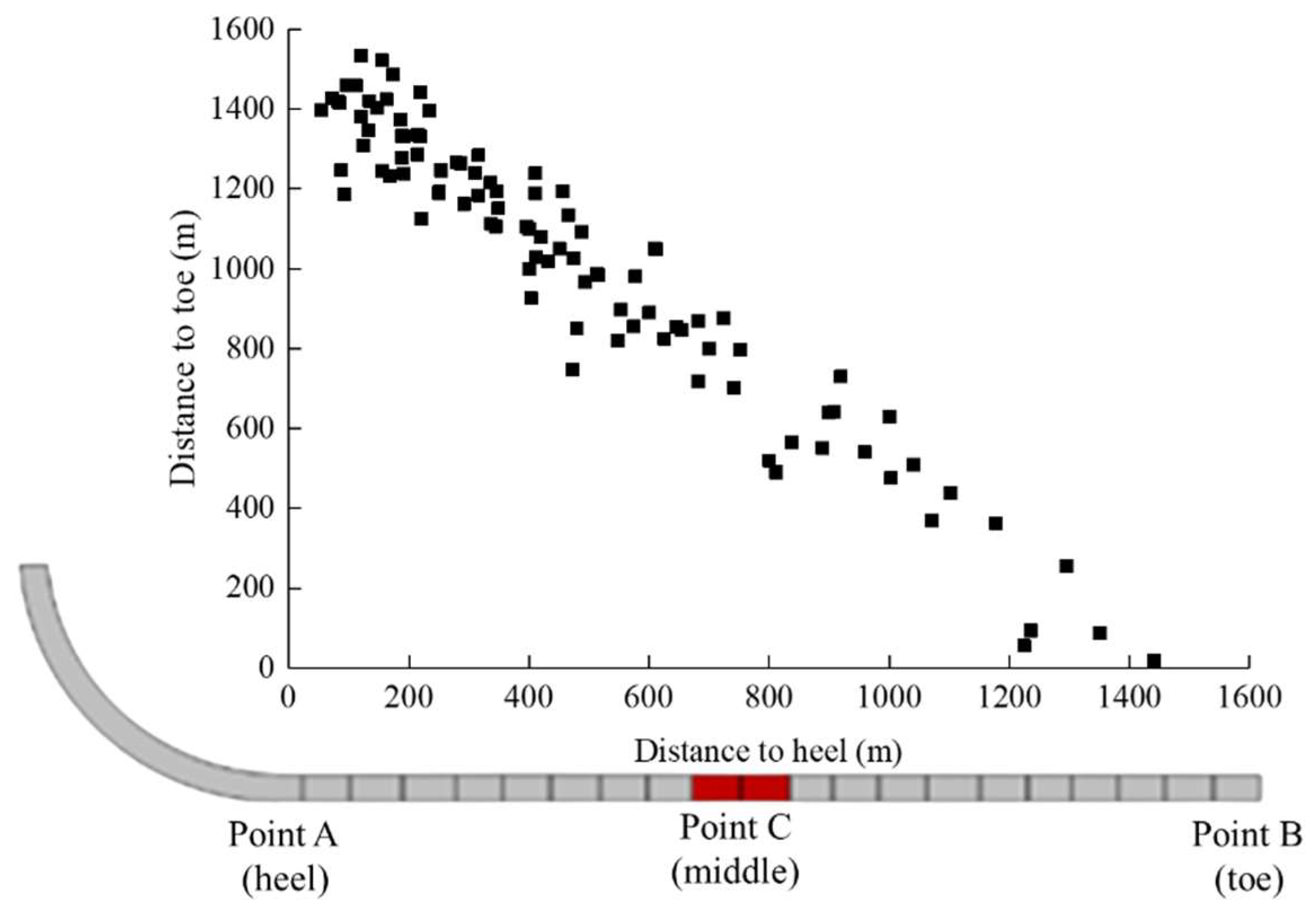
The distribution of the positions of casing deformation points is characterized as “dense near point A (landing point) and sparse near toe point C”;
(2)
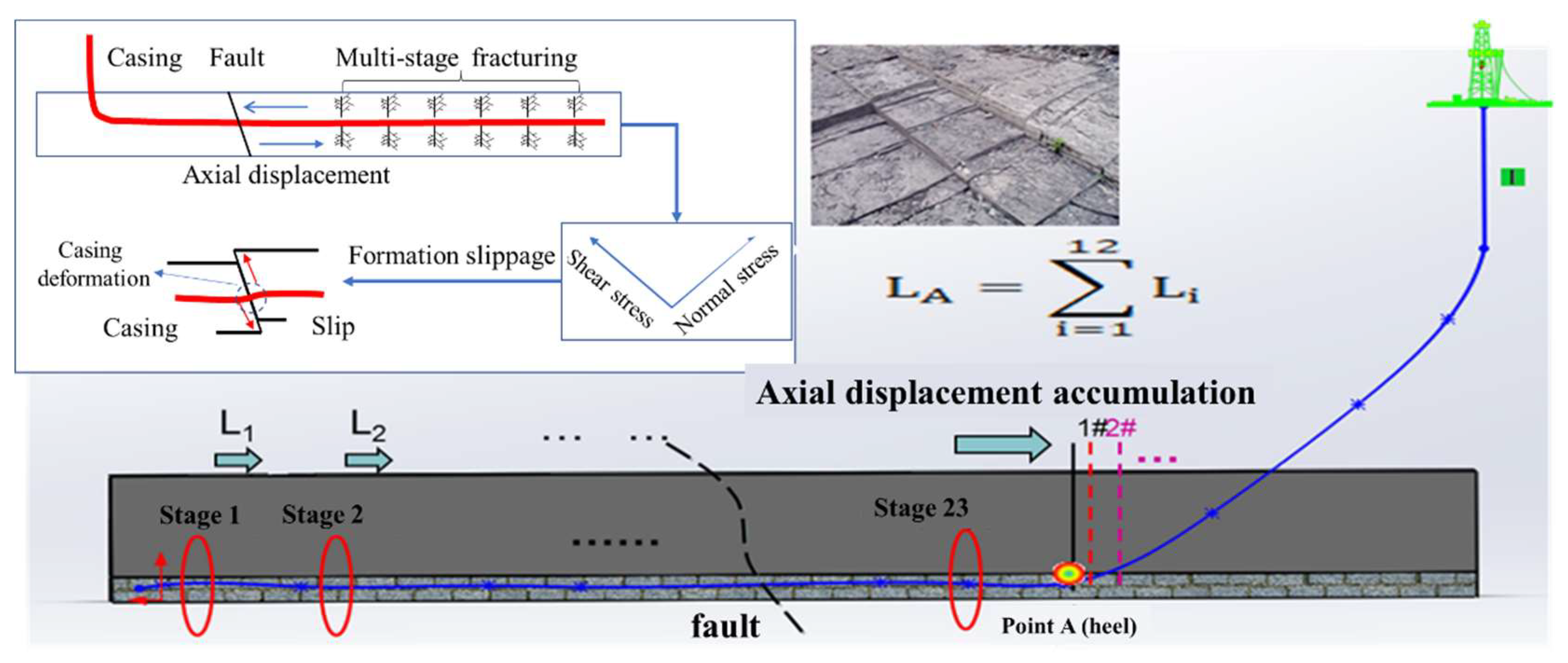
During multi-stage fracturing, fracturing fluid with large displacement and high pump pressure enters the formation, increasing the formation pore pressure. The fracture formation changes from initial compression to tension in the axial direction, squeezing the unfractured formation and resulting in the axial displacement of the unfractured formation. The closer the formation is to the heel, the greater the axial displacement;
(3)
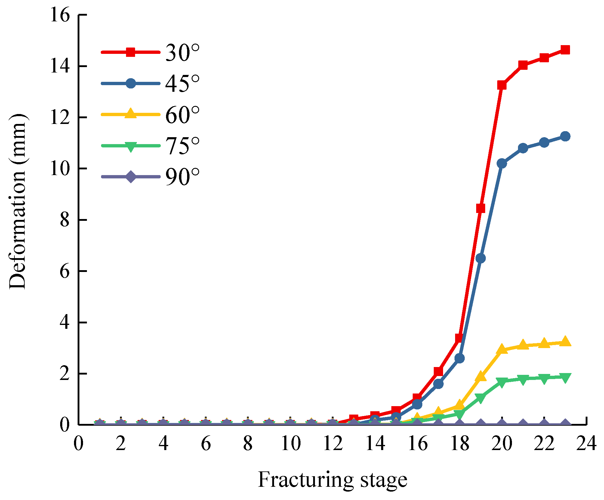
When the wellbore passes through a fault, the axial displacement of the formation along the wellbore during multi-stage fracturing will produce a displacement component along the fault plane, which will cause the casing to shear, leading to a reduction in the casing’s inner diameter. When the fracturing section is far from the fault, the casing deformation is approximately 0. When the fracturing section is close to the fault, the casing deformation increases rapidly. When the fracturing section is far away from the fault, the casing deformation increases slowly;
(4)
The closer the fault is to the heel, the longer the fault length, the smaller the dip angle, and the greater the casing deformation. Increasing the casing wall’s thickness and steel grade has little effect on relieving casing deformation. It is suggested that faults should be avoided in the wellbore design during field operations to prevent casing deformation.

Author Contributions

Conceptualization, software, writing—original draft preparation: W.L. and J.L. (Jun Li); software: J.L. (Jiayi Liu), Y.H. and X.C.; writing—review and editing: Y.Z. and Y.W. All authors have read and agreed to the published version of the manuscript.

Funding

This research was funded by [National Natural Science Foundation of China] grant number [52204018, U19B6003], [Innovative Environment Construction Plan (Innovative Talents) Project at Karamay] grant number [20212022hjcxrc0029, 20212022hjcxrc0037], [Research Foundation of China University of petroleum (Beijing) at Karamay] grant number [XQZX20220006].

Institutional Review Board Statement

Not Applicable.

Informed Consent Statement

Not Applicable.

Data Availability Statement

Not Applicable.

Acknowledgments

This work was jointly supported by the Research Foundation of China University of Petroleum-Beijing at Karamay and the Natural Science Foundation of Xinjiang Uygur Autonomous Region.

Conflicts of Interest

The authors declare no conflict of interest.

References

  1. Adams, N.J.; Mitchell, R.F.; Eustes, A.W.; Sampaio, J.H.B., Jr.; Antonio, A.O. A Causation Investigation for Observed Casing Failures Occurring during Fracturing Operations. In Proceedings of the SPE Hydraulic Fracturing Technology Conference and Exhibition, The Woodlands, TX, USA, 24–26 January 2017. [Google Scholar]
  2. Wu, X.; Han, L.; Yang, S.; Yin, F.; Teodoriu, C.; Wu, X. Numerical Study on Casing Integrity during Hydraulic Fracturing Shale Formation. In Proceedings of the SPE Oklahoma City Oil and Gas Symposium, Oklahoma City, OK, USA, 9–10 April 2019. [Google Scholar]
  3. Lian, Z.; Yu, H.; Lin, T.; Guo, J. A study on casing deformation failure during multi-stage hydraulic fracturing for the stimulated reservoir volume of horizontal shale wells. J. Nat. Gas Sci. Eng. 2015, 23, 538–546. [Google Scholar] [CrossRef]
  4. Jiang, K.; Li, Q.; Chen, Y.L.; Guo, X.L.; Fu, Y.Q.; Li, J. Influence of cementing quality on casing failures in horizonal shale gas wells. Nat. Gas. Ind. B 2015, 35, 77–82. [Google Scholar]
  5. Sugden, C.; Johnson, J.; Chambers, M.; Ring, G.; Suryanarayana, P.V. Special considerations in the design optimization of the production casing in high-rate, multistage-fractured shale wells. SPE Drill. Complet. 2012, 27, 459–472. [Google Scholar] [CrossRef]
  6. Zhang, W.F.; Fan, H.H.; Zha, Y.J. A recommended calculating method for casing bending force after large scale volume fracturing. China Pet. Mach. 2015, 43, 29–32. [Google Scholar]
  7. Tian, Z.L.; Shi, L.; Qiao, L. Research of and countermeasure for wellbore integrity of shale gas horizontal well. Nat. Gas. Ind. B 2015, 35, 70–76. [Google Scholar]
  8. Xi, Y.; Li, J.; Liu, G.H.; Cha, C.Q.; Fu, Y.Q. Numerical investigation for different casing deformation reasons in Weiyuan-Changning shale gas field during multistage hydraulic fracturing. J. Petrol. Sci. Eng. 2017, 163, 691–702. [Google Scholar] [CrossRef]
  9. Li, L.W.; Wang, G.C.; Lian, Z.H.; Zhang, L.; Mei, J.; He, Y.L. Deformation mechanism of horizontal shale gas well production casing and its engineering solution: A case study on the Huangjinba Block of the Zhaotong National Shale Gas Demonstration Zone. Nat. Gas. Ind. B 2017, 37, 91–99. [Google Scholar] [CrossRef]
  10. Yin, F.; Han, L.H.; Yang, S.Y.; Deng, Y.; He, Y.M.; Wu, X.R. Casing deformation from fracture slip in hydraulic fracturing. J. Petrol. Sci. Eng. 2018, 166, 235–241. [Google Scholar] [CrossRef]
  11. Li, J.; Li, Y.M.; Zhang, D.L.; Yang, H.W.; Sun, S.B. Analysis of casing damage for staged fracturing in shale gas well. Fault-Block Gas Field 2017, 24, 387–390. [Google Scholar]
  12. Yan, B.; Liu, F.J.; Wang, Q.C. Deformation law and strength evaluation method of casing in puguang gas field. China Pet. Mach. 2019, 47, 132–137. [Google Scholar]
  13. Li, H.T.; Li, Z.; Li, G.; Yu, H.; Jiang, Z.J.; He, L.; Guo, B.Y.; Dong, M.Z. Casing deformation mechanisms of horizontal wells in Weirong shale gas field during multistage hydraulic fracturing. J. Nat. Gas Sci. Eng. 2020, 84, 103646. [Google Scholar] [CrossRef]
  14. Liu, K.; Taleghani, A.D.; Gao, D.L. Calculation of hydraulic fracture indeced stress and corresponding fault slippage in shale formation. Fuel 2019, 254, 115525. [Google Scholar] [CrossRef]
  15. Chen, Z.W.; Zhou, L.; Walsh, R.; Zoback, M. Case Study: Casing Deformation Caused by Hydraulic Fracturing Induced Fault Slip in the Sichuan Basin. In Proceedings of the Unconventional Resources Technology Conference (URTEC), American Association of Petroleum Geologists, Houston, TX, USA, 23–25 July 2018. [Google Scholar]
  16. Chen, Z.W.; Xiang, D.G.; Zhang, F.S.; An, M.K.; Yin, Z.R.; Jiang, Z.Y. Fault slip and casing deformation caused by hydraulic fracturing in Changning-Weiyuan Blocks, Sichuan: Mechanism and prevention strategy. Pet. Sci. Bull. 2019, 4, 364–377. [Google Scholar]
  17. Liu, Q.L.; Liu, Z.; Guo, J.C.; He, L.; Li, N.C.; Zeng, Y.; Ren, S. Hydraulic fracturing induced casing shear deformation and a prediction model of casing deformation. Pet. Explor. Dev. 2021, 48, 394–401. [Google Scholar] [CrossRef]
  18. Guo, X.L.; Li, J.; Liu, G.H.; Xi, Y.; Zeng, Y.J.; He, M.; Yan, H. Numerical simulation of casing deformation during volume fracturing of horizontal shale gas wells. J. Petrol. Sci. Eng. 2019, 172, 731–742. [Google Scholar] [CrossRef]
  19. Zhao, C.J.; Li, J.; Liu, G.H.; Zhang, X. Analysis of well stress with the effect of natural fracture nearby wellbore during hydraulic fracturing in shale gas wells. J. Petrol. Sci. Eng. 2020, 188, 106885. [Google Scholar] [CrossRef]
  20. Chen, Z.W.; Shi, L.; Xiang, D.G. Mechanism of casing deformation in the Changning–Weiyuan national shale gas demonstration area and countermeasures. Nat. Gas. Ind. B 2017, 4, 1–6. [Google Scholar] [CrossRef]
  21. Chen, Z.W.; Wang, P.; Xiang, D. Analysis of casing deformation in the Changning-Weiyuan block based on focal mechanism. Pet. Drill. Tech. 2017, 45, 110–114. [Google Scholar]
  22. Li, H.; Deng, J.; Liu, W.; Li, Y.; Lin, S. Research on Casing Deformation Failure Mechanism during Volume Fracturing for Tight Oil Reservoir of Horizontal Wells. In Proceedings of the 51st US Rock Mechanics/Geomechanics Symposium, San Francisco, CA, USA, 25–27 June 2017; pp. 110–114. [Google Scholar]
  23. Yan, W.; Zou, L.; Li, H.; Deng, J.; Ge, H.; Wang, H. Investigation of casing deformation during hydraulic fracturing in high geo-stress shale gas play. J. Petrol. Sci. Eng. 2016, 150, 22–29. [Google Scholar] [CrossRef]
  24. Gao, L.J.; Qiao, L.; Liu, Z.L.; Zhang, Z.; Yang, H.L. Numerical modeling and cementing countermeasure analysis of casing shear damage in shale reservoir. Chin. Pet. Mach. 2016, 44, 6–10. [Google Scholar]
  25. Zhang, H.; Li, J.; Zhang, X.; Zhang, X.J. Analysis of casing deformation with the effect of natural fracture nearby wellbore in the Sichuan Basin. Pet. Sci. Technol. 2022, 40, 423–444. [Google Scholar] [CrossRef]
  26. Liu, H.; Liu, W.; Wang, S.L.; Dong, K.X. Research status and development trend of mechanisms of casing failure caused by volume fracturing in horizontal wells. J. China Univ. Pet. 2022, 44, 53–62. [Google Scholar]
  27. Tong, H.; Zhang, P.; Zhang, H.X.; Liu, Z.P.; Ren, X.H.; Xiao, K.Z.; Zhou, Y.B.; Deng, C. Geomechanical mechanisms and prevention countermeasures of casing deformation in shale gas horizontal wells. Nat. Gas. Ind. B 2021, 41, 189–197. [Google Scholar]
  28. Zhang, X.W.; Liu, J.D.; Cheng, W.; Jiang, W.D.; Jin, J.; Shen, L.H. New Type of Casing Deformation Rising in Weiyuan-Changning Shale Gas Play. In Proceedings of the International Petroleum Technology Conference, Riyadh, Saudi Arabia, 21–23 February 2022. [Google Scholar]
Figure 1. Casing deformation morphology: (a) shear deformation and (b) squeeze deformation.
Processes 10 02421 g001
Figure 2. Statistics on casing deformation of some shale gas wells.
Processes 10 02421 g002
Figure 3. Distribution features of the casing deformation points.
Processes 10 02421 g003
Figure 4. Distribution of casing deformation points.
Processes 10 02421 g004
Figure 5. Calculation model of axial formation displacement.
Processes 10 02421 g005
Figure 6. Casing deformation calculation model with faults.
Processes 10 02421 g006
Figure 7. Results of different fracturing zones.
Processes 10 02421 g007
Figure 8. Comparison of the axial displacements of the formation at different positions.
Processes 10 02421 g008
Figure 9. Axial displacement cloud diagram of strata: (a) 12th fracturing; (b) 23rd fracturing.
Processes 10 02421 g009
Figure 10. Effect of the initial Young’s modulus on the displacement at point A.
Processes 10 02421 g010
Figure 11. Schematic diagram of fault slip caused by a multi-stage fracturing operation.
Processes 10 02421 g011
Figure 12. Casing shear deformation in different positions.
Processes 10 02421 g012
Figure 13. Effect of casing thickness on casing deformation.
Processes 10 02421 g013
Figure 14. Effect of casing steel grade on casing deformation.
Processes 10 02421 g014
Figure 15. Influence of fault length on casing deformation.
Processes 10 02421 g015
Figure 16. Influence of fault inclination angle on casing deformation.
Processes 10 02421 g016
Table 1. Geometric, mechanical, and physical parameters of casing–cement sheath-formation assembly.
NameOuter Diameter
(mm)
Young’s Modulus
(GPa)
Poisson RatioPermeability
(mD)
Porosity
(%)
Yield Strength
(MPa)
Density
(kg/m3)
casing139.72100.3--7588000
cement sheath215.9120.170.0010.2-1893
formation-400.25000.35-2000
Publisher’s Note: MDPI stays neutral with regard to jurisdictional claims in published maps and institutional affiliations.

