Article

Comparative Study on Snowflake Dendrite Solidification Modeling Using a Phase-Field Model and by Cellular Automaton

1
College of Chemical Engineering, Beijing University of Chemical Technology, Beijing 100029, China
2
Faculty of chemical engineering, Kunming University of Science and Technology, Kunming 650031, China
*
Authors to whom correspondence should be addressed.
Processes 2022, 10(11), 2337; https://doi.org/10.3390/pr10112337
Submission received: 1 September 2022 / Revised: 7 November 2022 / Accepted: 8 November 2022 / Published: 9 November 2022
(This article belongs to the Special Issue Research on Process System Engineering)

Abstract

:
Dendrite is among the most frequently observed structures during the solidification process. Different dendrite morphologies caused by environmental conditions can affect the physical properties of materials. The formation of snowflakes can generate various morphologies under different conditions, and is used in this work as an example. Simulation technologies provide insight into the correlation between a resulting morphology and its impact parameter, including the phase-field method (PF) and cellular automaton (CA). The PF method is derived from thermodynamic functions and kinetic equations, while the CA model is established by interaction rules between subsystems. It is difficult to solve the PF method due to the coupled differential equations, wherein the actual physical parameters are included. The CA model is conceptually simple and computationally efficient; however, the physical meaning of the parameters is absent. In this work, an example of snowflake formation is considered by PF with all the impact factors defined first, and then parameters in CA are searched by iterations to approximate the result, i.e., latent heat and the anisotropic coefficient in the PF method correspond to the initial distribution and the environmental effect in the CA model. In addition, the discrete time of each iteration in the CA model is identified according to the dendritic growth speed of these two models. A systematic identification process for the CA parameters’ physical meaning is demonstrated by the comparison with the PF method, and an approximate simulation of the PF method can be obtained simply by the CA model. The combination of the PF method and the CA model can be used to investigate the influence of environmental factors on dendritic morphology.

1. Introduction

Various morphologies are produced during the solidification of substances, which affect the physical properties of materials. Therefore, understanding the impact of the growth environment on dendritic morphology is crucial for certain engineering applications [1]. In the research of lithium batteries, dendritic deposited lithium can pierce through the separator and cause internal short circuits, while uniformly deposited lithium can lengthen the battery cycle life [2]. Morphology control of deposited lithium is a major challenge for the development of lithium metal batteries. Available control methods are focused on the modification of an electrolyte with additives [3], artificial SEI [4], and nanostructured electrolytes [5]. However, most of these methods are context dependent, and the dendrite growth mechanism still requires further clarification.
The dendrites growth process can be demonstrated by simulation techniques, which are convenient to investigate the influence of environmental parameters. For the formation process of lithium dendrite, many substances are involved due to the multi-component environment of the electrolyte solution [6], which leads to the existence of several side reactions. A pure reaction-diffusion process of a single substance is simpler to simulate and can be considered as a foundation to study the essential mechanism of the multi-component system. A variety of morphologies can be produced by single-molecule water crystallization under different environmental conditions, which is a suitable alternative to studying the relationship between dendrite morphologies and parameters.
Some classical snowflake shapes are summarized through early experiments including artificial and natural ice crystals [7]. Supersaturation and temperature have been proven to be two crucial factors related to the diversity of this phase transition process. More specifically, the temperature is the main factor to control the morphology of snowflakes, and supersaturation is more decisive in the growth rate. Although the types of snowflake morphology have been obtained by experiments, the underlying physical mechanism remains controversial. From the research on the physical dynamics of ice crystal growth, the formation of snowflakes represents an interaction effect at length scales ranging from the molecular to the macroscopic [8], and it is largely controlled by a combination of molecular attachment kinetics on faceted surfaces and diffusion process of heat and particles [9]. Numerous models are proposed to describe the growth process, such as the surface diffusion model of Mason [10] and the layer nucleation rate theory by Nelson [11].
Exploring the effect of physical parameters on dendritic structures by experiments is expensive in cost and time. The theoretical physical model can describe the snowflake growth data by calculating the condensation coefficient and growth rate, but it is limited in expressing the dendrite morphology intuitively. The dynamic simulation of the growth process of snowflakes provides a space-time evolution of dendrites morphologies. Cellular automaton and the phase-field method are the two dominant technologies for snowflake growth simulation.
Cellular automata (CA) are computational algorithms that rely on a few relatively simple local rules and are realized through parallel computation, which was first proposed by von Neumann [12]. The CA framework has been proven to be useful for complex systems simulations in various scientific fields, and one prominent research area is the crystallization process. Clifford [13] established a CA model that was realized on hexagonal grids to generate abundant snowflake patterns, which is an effective tool to investigate different snowflake morphologies. Simple transformation rules of cells are applied in this model; however, this CA model is inapplicable in analyzing the actual environment condition influence. Based on the Clifford model, Liu [14] explored the model parameters systematically and considered the vapor density and supersaturation, but no specific connection between model parameters and supersaturation was addressed. CA models perform well in reproducing the actual physical process, while it is intrinsically difficult to extrapolate to other similar processes by one transformation rule. Although constructing the transition functions based on intuition is an advantage, it reduces the interpretability of the model.
The phase-field method (PF) is a general technique to explore the interface evolution process derived from thermodynamic functions and kinetic equations [15]. The interface can be tracked by introducing order parameters to represent different phase states, which allows us to study the evolution process of arbitrary complex morphology [16]. PF was originally used to study the dendrite evolution process of the alloy solidification process by Kobayashi [17], and the anisotropic parameters were introduced into the model to obtain the various dendrite morphology. Starting from the KKS [18] model and anisotropic parameters, Chen [19] simplified the free energy density with the dilute solution approximation method to construct the ice crystal PF model, and the effect of anisotropy on the formation of snowflakes was explored. G. Demange [20] proposed a 3D snowflake PF model based on a single Lyapunov functional, and considered the role of vertical attachment dynamics in the growth process of ice crystals, the model combines the PF model and physical theory to improve the physical meaning. Although PF has achieved the simulation of the crystallization process by defining global equations compared to the more complex sharp-interface modeling methods [21], the computational cost used for such free boundary problems is much higher than CA, especially concerning the complex multi-material phase transition processes, and it is almost impossible to identify the PDEs’ parameters from the experimental data.
In this paper, the PF and CA methods are adopted to simulate the snowflake growth process. Firstly, the influence of the parameters in both models on the final simulated snowflake patterns is discussed. Secondly, the snowflake morphologies produced by both methods are somewhat similar under different parameters, and the physical processes of these situations are explained to deepen the physical meaning of the parameters. The method of image recognition is adopted to obtain the snowflake growth rate of both simulation methods. The correspondence of model parameters from both methods are investigated by qualitative analysis. It is concluded that both models are similar in growth rate and the physical meaning of the parameters in CA can be illustrated by the comparison with PF. The results make it possible to combine the computational efficiency of CA with the advantages of an accurate solution of the PF method for subsequent research in crystallization.

2. Methods

2.1. Snowflake Model Based on CA

CA is established based on flexible interaction rules between units, which are not limited to closed and continuous assumptions, and pays more attention to local mechanisms. In the case of CA snowflake models, a hexagonal grid has always been adopted for the reason that the ice crystal is hexagonal and has sixfold symmetry, and the cell states have always been divided into crystal cells and liquid cells. The side length is set to 200 hexagons. The state of the system is uniform, and there is only one crystalline lattice in the center, which is the starting point of crystallization. The initial value of the central grid in the computational is 1, and the rest of the grids are set to a background value of β between 0 and 1, representing uniform distribution. The different β values represent different environmental supersaturations. The value of the cell is denoted by S, and a grid value of S greater than or equal to one means that the water vapor transforms into a crystalline state. The neighbor rules for this CA are discussed in detail below.
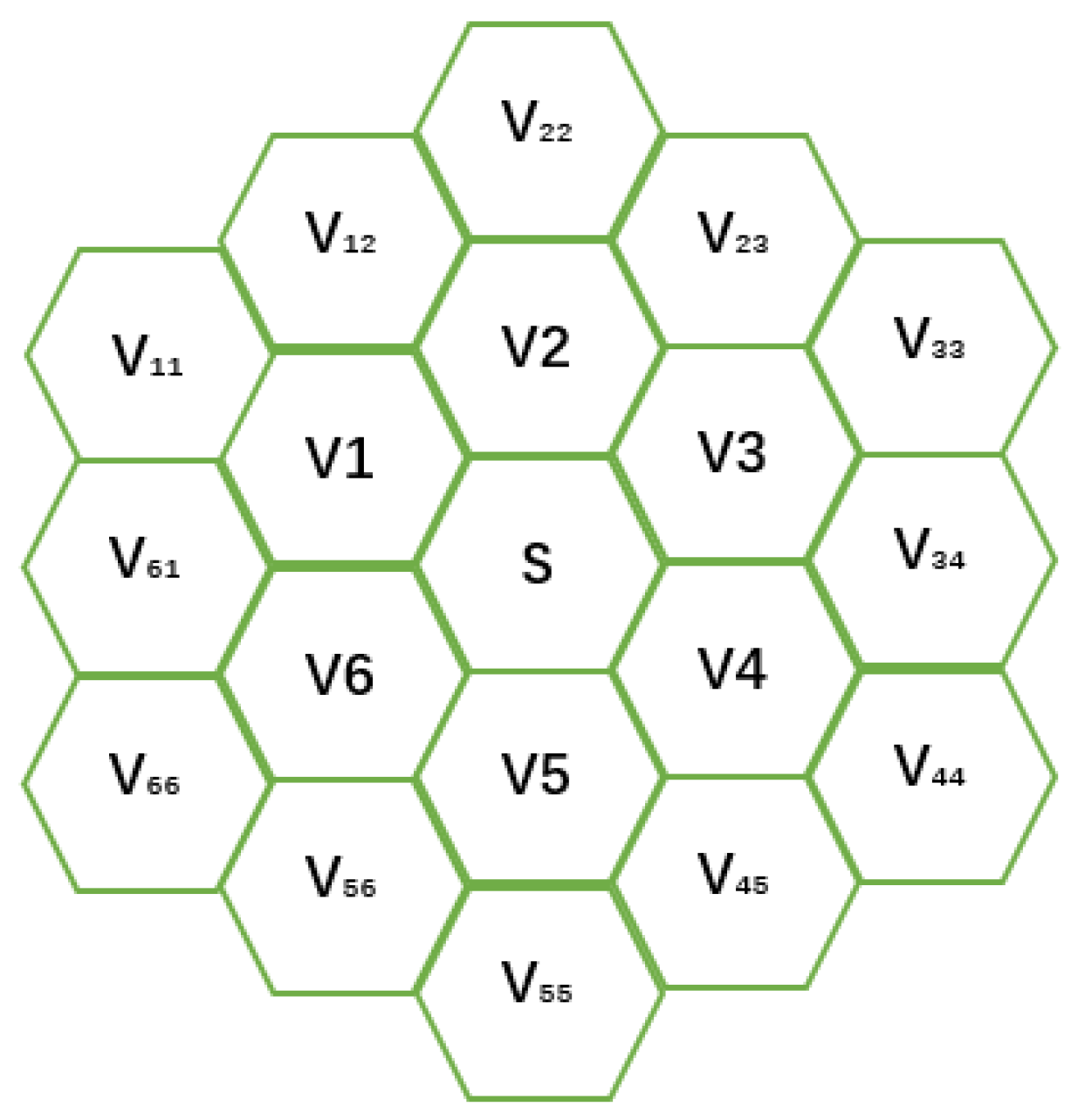
The neighbors of the CA model are selected as the two layers of lattices around the central cell, as shown in Figure 1. The lattice of the cell space will be represented by different variables. The value of the center grid is set as S, and the values of the first circle grids are set as V1 to V6. The second circle grids are divided into two types, for the grids connected to the first circle grids by only one edge are V11 to V66, and for the grids with two edges in contact with the first circle grid are set to V12, V23, V34, etc. Further, for the convenience of demonstration, the phase states are distinguished by three different colors—orange represents the crystallized grid, white represents the uncrystallized grid, and blue represents the grid adjacent to the crystallized grid. To describe the growth rules of snowflakes, the γ parameter is used to express the vertical direction growth rate and is added at each update. The state value S of a cell at the next time is determined by the state value of the cell and its neighbors at this time. The specific cell rules will be described below.
S t + 1 = S t + γ
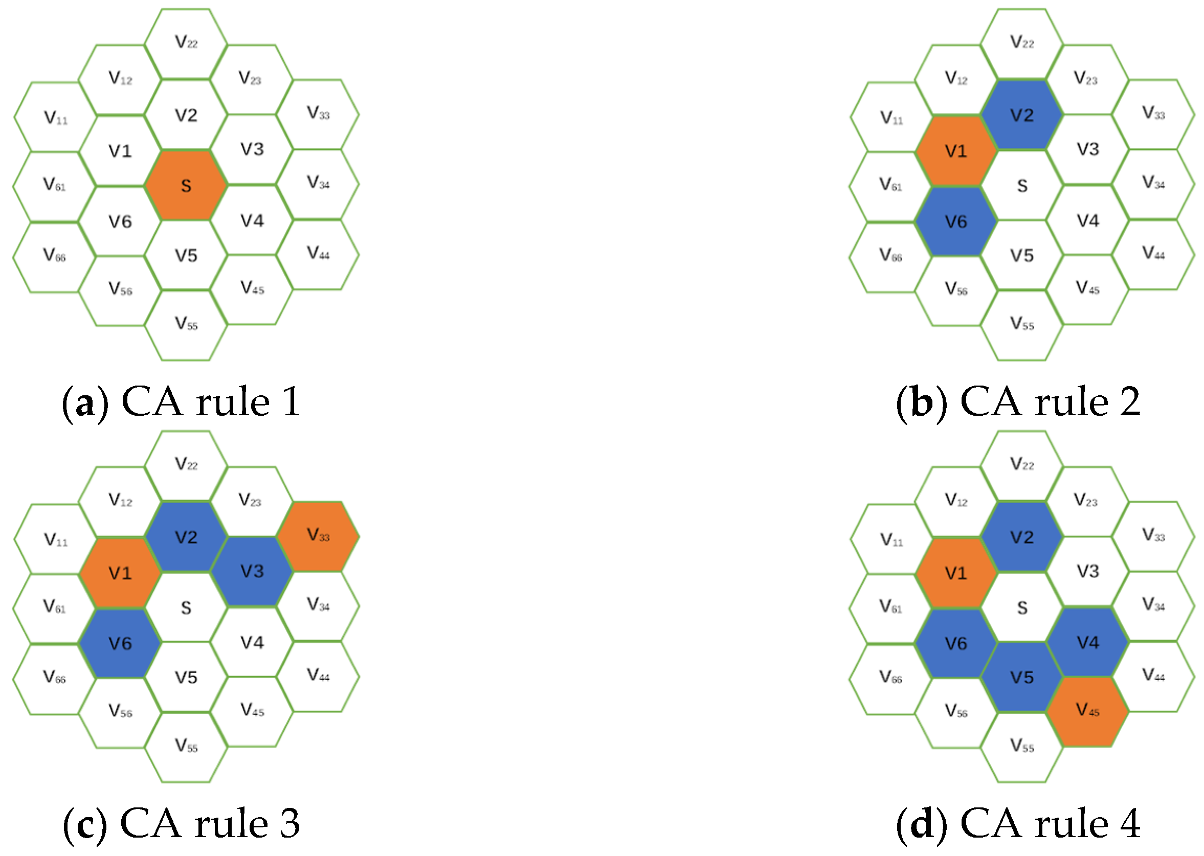
If the state of the central lattice is less than 1, this means that the central lattice is not crystallized. The change in the state of the center cell will become a little complicated. At the next moment, the state value S of the central cell needs to be determined according to its state and the state of its neighbors. Firstly, it is discussed that there are crystalline cells (orange cells) only in the first circle neighbors (V1 to V6), as shown in Figure 2b. This crystalline cell will make the state (Vi) of itself and the two surrounding cells (blue cells) equal to 0 when calculating the state of the central cell next time. The formula for calculating the center cell state S at the next moment is (2)
S t + 1 = S t + γ + 1 6 V i t / 12
Similarly, for Figure 2c, if there are crystalline cells (orange cells) in both the first circle neighbors and the second circle neighbors of the center cell, the calculation formula of the center cell state S at the next moment is also (2).
Figure 2d shows two different surrounding cases (blue cells) of cells with crystal states in the second circle of neighbors at the same time. If there is no crystalline cell in the first circle neighbors, but there are crystalline cells in the second circle neighbors, the next moment of the center grid is calculated by (3):
S t + 1 = 0.5 × S t + γ + 1 6 V i t / 12
Finally, if there are no crystal cells in all neighbors, the next time center state value S is calculated by Formula (1).
The summary rules are shown in Figure 3. The state value of the central grid needs to be judged first, then different calculation rules according to the state values of the two-layer neighbors are selected.

2.2. Snowflake Model Based on PF

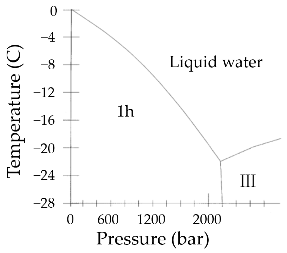
The phase field model is a model that adopts a continuous state variable to represent the change of the phase interface, which is usually called the order parameter. A diffusion interface will be generated numerically, which avoids the problem of setting boundary conditions for different phases. During the crystallization and solidification of pure water, the distribution of temperature and the movement of the interface should be concerned, which is generally denoted as Stefan-type problems or “moving boundary problems”. The water phase diagram is shown Figure 4 below; according to the phase diagram, ice crystals can be formed at temperatures below 0 °C under atmospheric pressure.
The PF equations are derived strictly based on general thermodynamics and kinetic principles. According to the PF model proposed by Kobayashi [17], P is the order parameter, and when P is 1 or 0, this represents the solid phase and the liquid phase, respectively. Using the Ginzburg–Landau free energy functional, as shown in Equation (4)
Φ = 1 2 ε 2 P 2 + F P , m dr
where ε is the anisotropic gradient energy coefficient that determines the thickness of the interface, anisotropy can be introduced by assuming that ε is related to the direction of the normal vector outside the interface, thus we consider
ε = ε ¯ 1 + δ cos [ j θ θ 0 )
where ε ¯ represents the average interface anisotropy gradient energy coefficient, δ represents the anisotropic strength, j represents the anisotropic modulus, which means the principal branch number, θ is the angle between the normal vector direction outside the interface and the coordinate direction, and θ 0 is the initial angle.
m is a function related to temperature, in the form shown in Equation (6)
m T = α π a r c t a n μ T e T
α is a constant as the temperature coefficient, μ is the supercooling coefficient, and T e is the equilibrium temperature, which means that the driving force of interfacial motion is proportional to the supercooling. F is a double-well potential function, which reaches the minimum value when P is 1 or 0. The expression of F is shown in Equation (7).
F P , m = 1 4 P 4 1 2 1 3 m P 3 + 1 4 1 2 m P 2
According to the Allen–Cahn equation τ P / t = δ Φ / δ P , combined with the enthalpy conservation equation, the PF equations are obtained by (8)–(10)
T t = 2 T + K P t
τ P t = · P 2 ε ε P + · ε 2 P + P 1 P P 1 2 + m + A n
A n = X 0 P   1 P   ×   random 0.5 ,   0.5
where T is the dimensionless temperature, τ is the relaxation time, K is the dimensionless latent heat, which is proportional to the latent heat and inversely proportional to the cooling intensity, and A(n) is the noise term, which is used to simulate the interference effect of the solid–liquid interface, random 0.5 ,   0.5 represents a random number from −0.5 to 0.5, and X 0 is the noise intensity. The presence of noise promotes the growth of dendrites in ice crystals. The simulation process of the PF equations is calculated by the finite difference method, and the five-point template method is adopted in the two-dimensional space. Additionally, the time integration adopts the simple explicit Euler time advance format. The region of calculation is considered as 30   μ m × 30   μ m . The simulation grid extents are Nx = 1000, Ny = 1000 and grid spacing dx = dy = 0.03 μ m . The meshing has passed the test of grid independence, and the results will not change much even if the accuracy is improved. To promote the solidification process, the radius of the crystal nucleus is set to 5 μ m in advance in the simulation unit stable nuclei. The discrete time dt is 0.0001 s, and the total number of iterations is 8000.
The discrete process of divergence can be derived by Equation (11)
· φ F = φ · F + φ · F = φ x · F x + φ y · F y + x φ F x + y φ F y
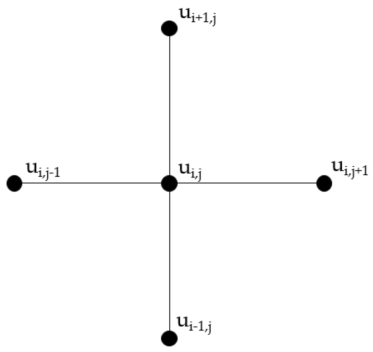
The Laplace operator of the five-point template method is represented in Figure 5, the second derivative of a certain point is calculated by using the four surrounding points in the finite difference method, and the expression is shown in (12).
2 u i , j = Δ 2 x x u i , j + Δ 2 y y u i , j                         = u i + 1 , j 2 u i , j + u i 1 , j d x 2                         + u i , j + 1 2 u i , j + u i , j + 1 d y 2 .
The parameters used in the PF model are presented in Table 1. The descriptions of each parameter can be found in the Appendix A.

3. Results and Discussion

Both methods are carried out in the environment of the Lenovo R9000P computer, in which the CA model is implemented in Python software, and the PF method is implemented in MATLAB.

3.1. Simulation Results of the CA Model

The model parameters of the CA model in the previous chapter are adopted so that the background water vapor parameter β is set to 0.5, the vertical growth parameter γ is set to 0.00, and the number of iterations is set to 2000. The result is shown in Figure 6.
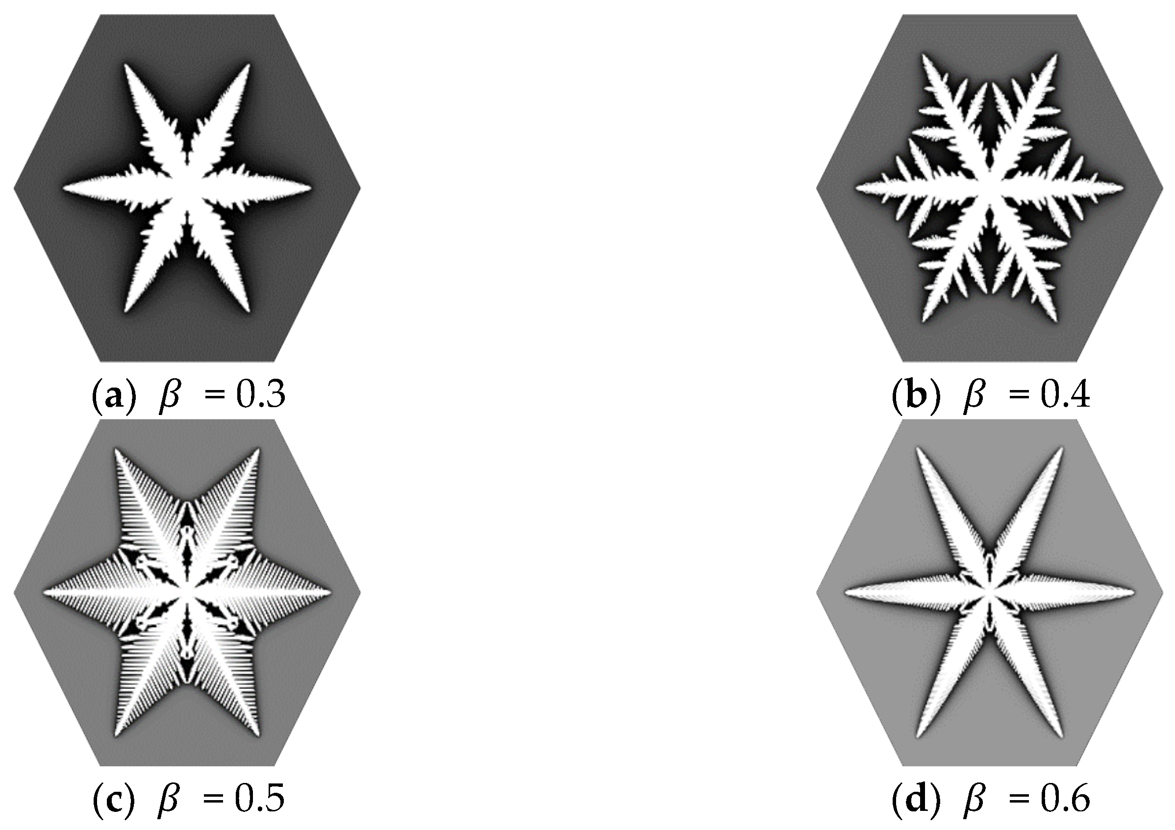
It can be seen that the snowflake growth process is simulated by CA from the figures. The morphologies of snowflakes are greatly changed by different parameters. The simulated snowflake morphologies of different background parameters β are shown in Figure 7 when the vertical growth parameter γ is set to a constant 0.001.
It can be seen from Figure 7 that when the parameter β increases, the shape of the main crystal branch becomes thinner, and the growth of the side crystal branch increases. However, when β increases to a certain extent, the side branch slowly grows again. Snowflakes tend to have a sharper, more relaxed structure on the main branch. At the same time, the water vapor density β affects the growth rate of dendrites, and the decrease in β results in slower dendrite growth. The vertical growth parameter γ also has a great influence on the snowflake crystal morphology as shown in Figure 8; when β is set to 0.5, the effect of different γ values on the snowflake morphologies are shown below.
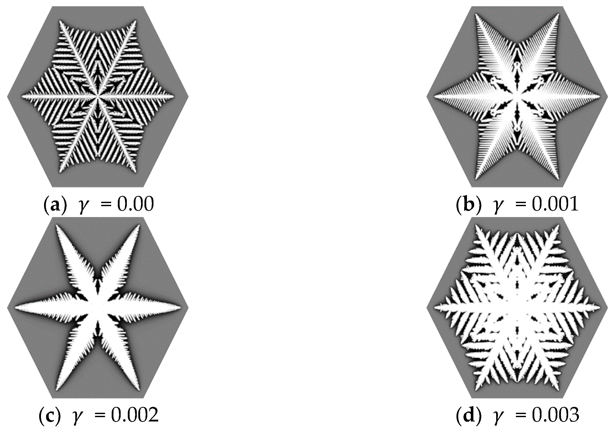
It can be seen from Figure 8 that the larger the vertical growth parameter γ , the thicker the main branch, and the shorter and denser the side branches. However, after reaching a certain level, the snowflakes are more inclined to form a compact morphology; and as the parameter γ continues to increase, a plate-like hexagonal snowflake is finally formed.

3.2. Simulation Results of the PF Method

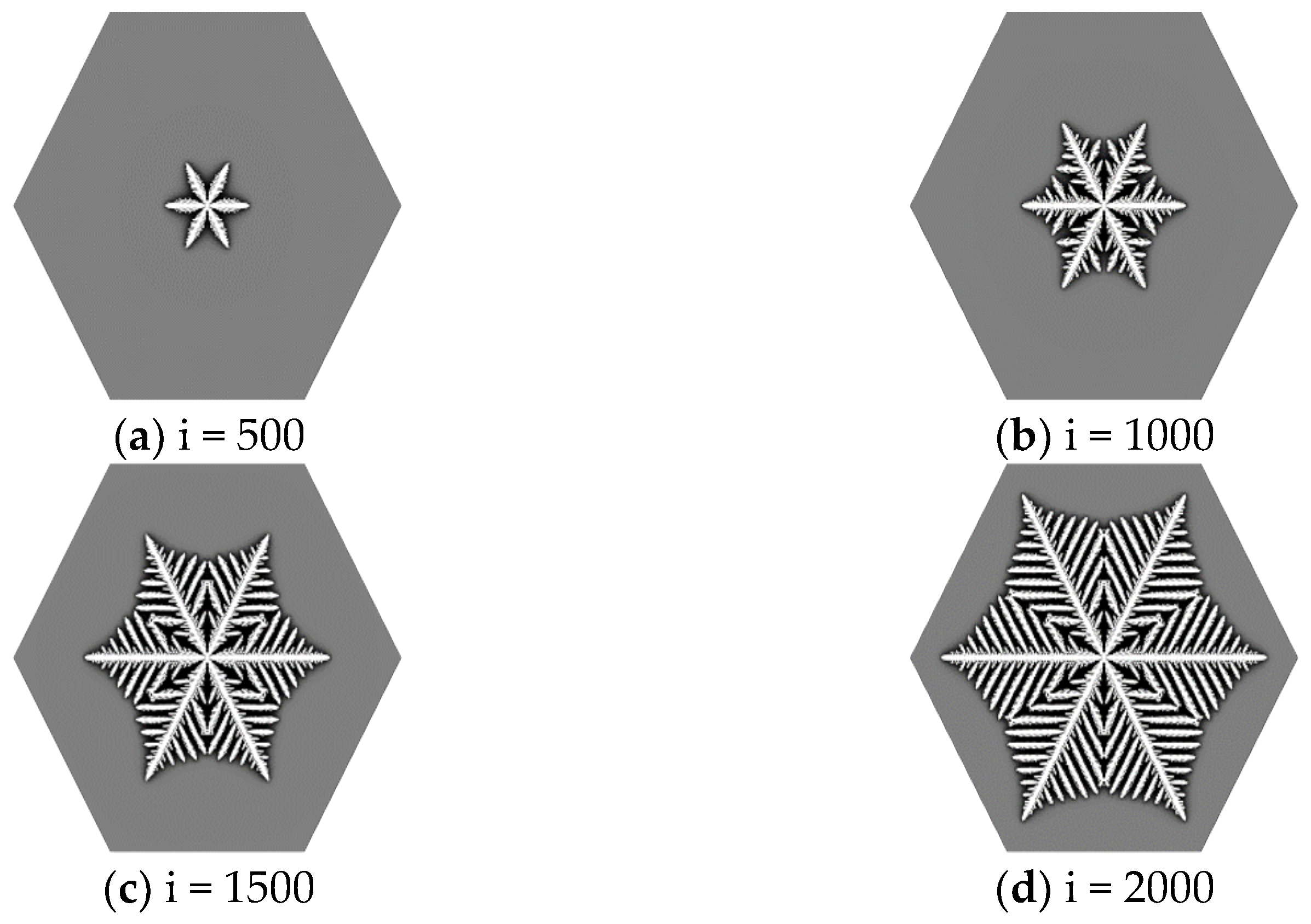
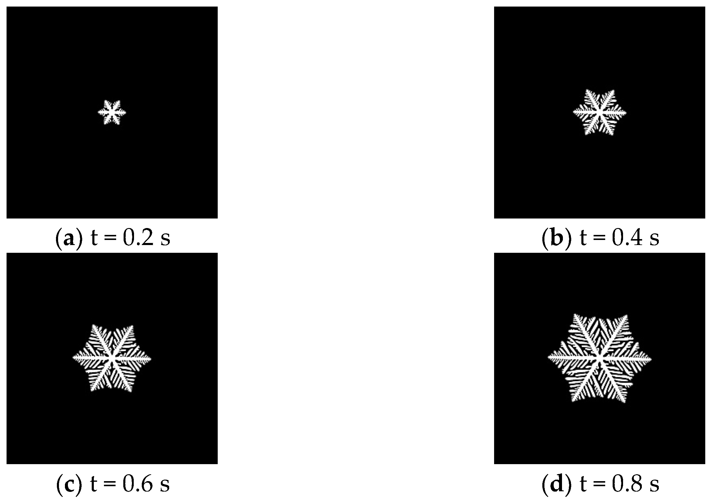
According to the PF method described in Section 2.2, the ice crystal growth process is simulated using the finite difference method, and the PF parameters use the data in Table 1. The phase-field model simulates the evolution of the snowflake growth process over time, and the results are shown in Figure 9.
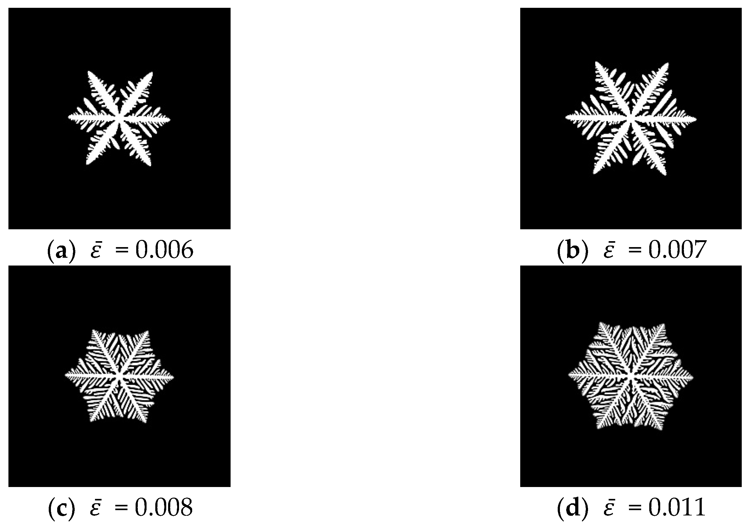
It can be seen that the PF method can also simulate the growth process of snowflakes, and the parameters in the PF method also affect snowflake morphology. The effect of the anisotropic gradient energy influence of coefficient ε is shown in Figure 10.
It can be seen that with the increase in anisotropic gradient energy, the growth rate of the dendrite accelerates, the main branches become thinner, new branches are formed on the side branches, and the snowflakes are more inclined to form a compact and dense morphology. In addition, we also need to pay attention to the fact that the changes in parameters in the PF method are more regular than in the CA model. On the one hand, the parameters of the PF method obtain physical meaning; on the other hand, the neighbor rules of the CA model are difficult to derive a quantitative formula such as the PF method.

3.3. Comparison of the Simulation Results of the Two Models

There are three questions to be discussed in the pure water solidification problem: (1) the evolution of the solid fraction, (2) the evolution of the phase state, and (3) the interface geometry problem. They are investigated from different aspects by CA and PF. The solid fraction is described by the state value of lattices in the CA model, while it is specified by the order parameter in the PF model. The threshold values are specified to define the phase state by both methods. A hexagonal mesh is applied in CA to demonstrate the sixfold symmetry of ice crystal dendrite growth, which is described by the anisotropy function in PF. The dendrite growth process and various morphologies are simulated by both methods, and the relation of the model parameters is discussed below.

3.3.1. Comparison of the Growth Parameters of Two Methods

There are only two environmental parameters of the CA model, while many environmental parameters are included in the PF method, and these parameters are classified into the parameters β and γ by the CA model. PF and CA are used to simulate the classical snowflake patterns in three different environments, and the physical interpretation of the model parameters is given to identify the relationship between the model parameters of the two methods.
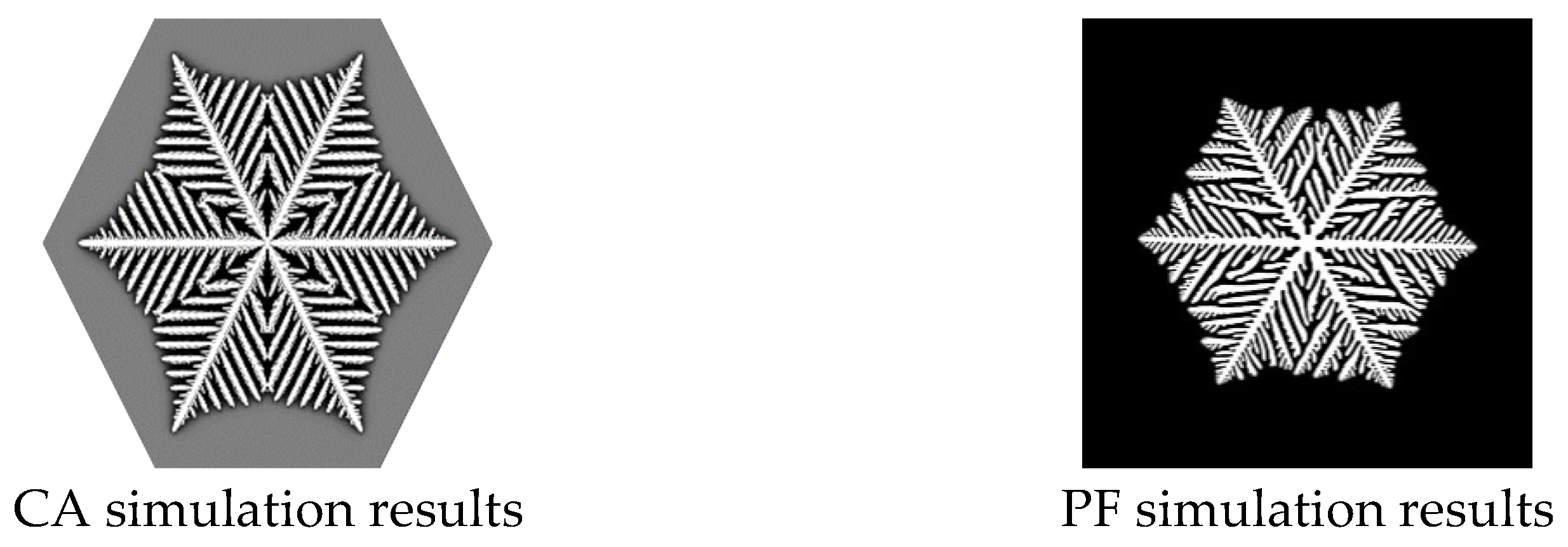
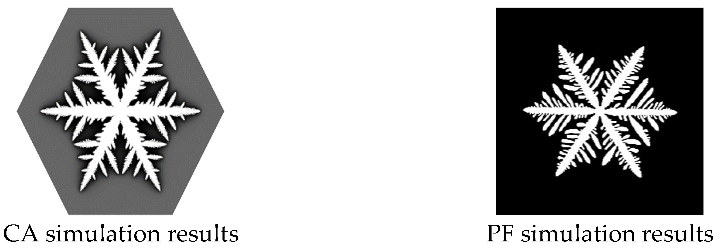
A classical snowflake pattern is simulated by CA and PF in Figure 11. The β parameter and γ parameter are set to 0.5 and 0, respectively, while the PF parameters are shown in Table 1. The dendrite growth results with sixfold symmetry are simulated by both methods, and the secondary arms are arranged alternately in long and short forms, which can be seen in the simulation results. The simulation of this snowflake pattern by CA and PF shows significant similarity in the overall and microscopic morphologies.
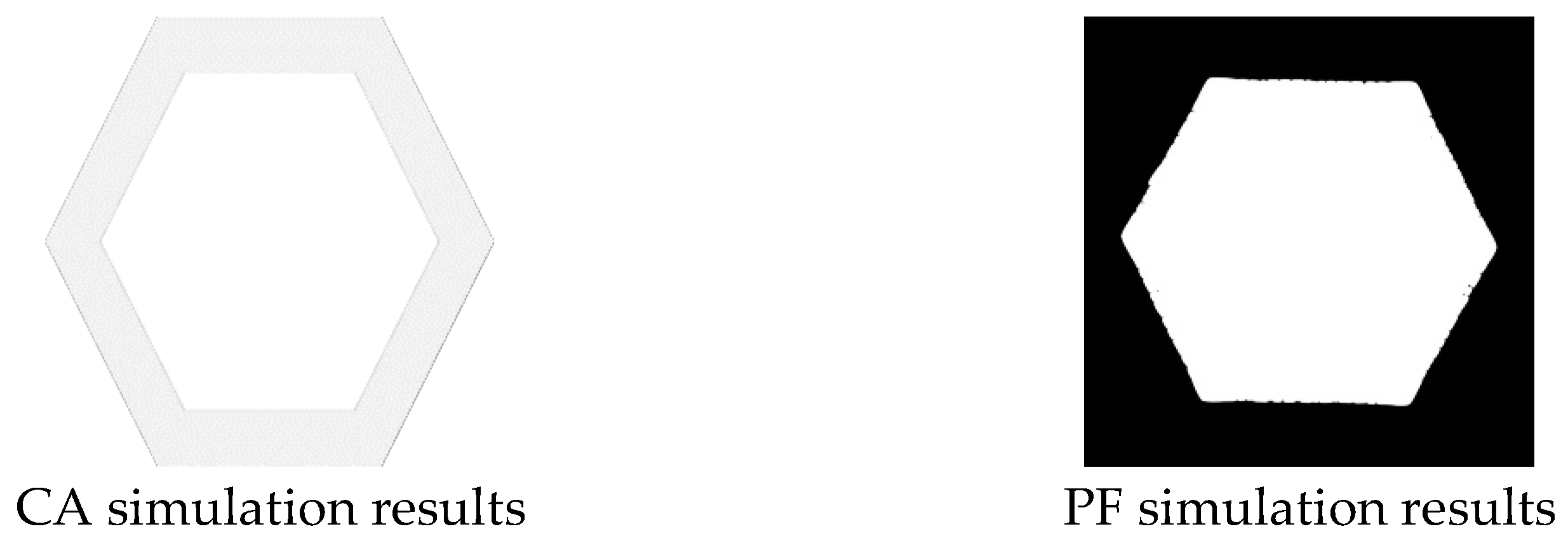
In addition to the classical simulation of hexagonal symmetric snowflake dendrite morphology, the hexagonal snowflake is another common snowflake pattern and usually occurs at lower temperatures according to the experiments [7]. Dendrite free is considered as a special form of dendrite, and the relationship between parameters and the morphology of dendrite is worth investigating. In the CA model, the initial background state value β is adjusted to 0.95 and the γ parameter is set to 0.05, which can simulate the hexagonal plate snowflake. In the PF model, dimensionless latent heat K is adjusted to 1 after testing, and other parameters are consistent with those in Table 1; the morphology of hexagonal snowflakes can also be obtained. These simulation results are shown in Figure 12. It should be noted that there are two ways to simulate a hexagonal snowflake by CA, and the other way is to set the γ parameter to 1, which makes all the lattices crystalline, while the β parameter does not play any role. It can be observed that the growth process of snowflakes is indeed in the form of hexagonal growth by the former model parameters. However, the colors of the crystallization region and the liquid phase region in the simulation results are close to each other due to the high β value, which makes it difficult to distinguish. In the PF model, the growth of snowflakes gradually changes from dendrite growth to plate growth by continuously decreasing the value of K, which is similar to the growth model of the CA model. By analyzing the physical meaning of K, it can be seen that the latent heat generated by the phase transition in the process of snowflake growth will affect the formation of the secondary arm and cause the change in morphology.
The simulation of the CA model is another classical snowflake pattern when the β parameter of the CA model is set to 0.4, and the γ parameter is set to 0.01. The PF method can simulate a similar snowflake pattern when the mean anisotropic gradient energy coefficient is set to 0.007 and other parameters are adopted in Table 1. As shown in Figure 13, the primary branches are thicker than the snowflakes in Figure 11, and the secondary arms are distributed at wide intervals. The mean anisotropic gradient energy coefficient is proved to adjust the morphologies of snowflake dendrite. According to the above comparison, the background parameter β and the vertical growth parameter γ in CA have some connection with the dimensionless latent heat K and the anisotropy parameter ε ¯ in PF.

3.3.2. Verification of Growth Similarity of Two Methods by Growth Rate

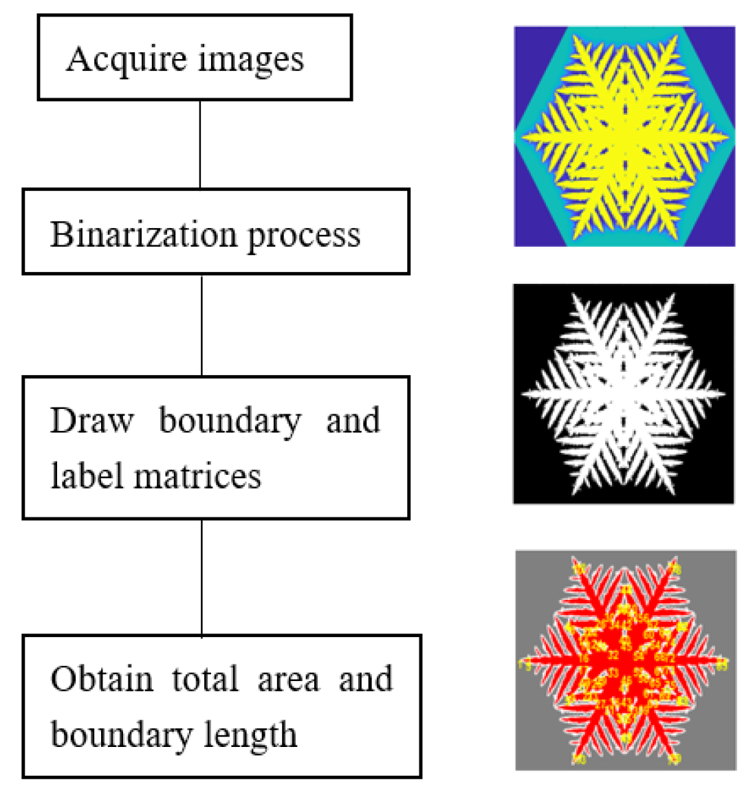
The MATLAB image recognition techniques are used to obtain the crystal side length and total area in the snowflake growth process. The dendrite morphology figures are binarized, and the boundary and total growth area of the dendrite can be obtained by using the built-in boundary identification function. The specific process is shown in Figure 14.
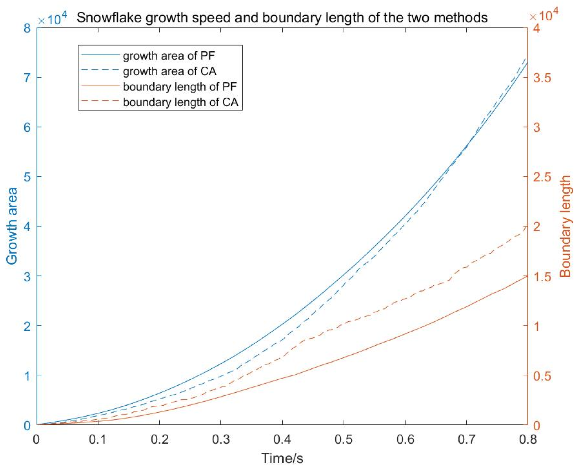
According to the comparison of snowflake morphologies in Section 3.3.1, the classical snowflake pattern in Figure 11 can be simulated by both the CA and PF methods, and the growth areas and boundary length of the snowflake growth process are obtained by the image recognition techniques. The simulated images of CA and PF are unified to the same pixel size of 800 × 800, and the growth curves of both simulation methods have similar parabolic growth trends. Since PF represents the evolution process by discrete time, while CA takes the number of iterations, it is considered to multiply a time scaling factor with the CA model’s iteration numbers to obtain a uniform time scale. The iteration number of the CA model is corresponding to the physical time of the PF model with the same growth area, then the time of one iteration can be obtained through dividing the physical time by iteration number. The time scaling factor is set to 0.00048 s for one iteration, in which the growth rate in CA is matched with that in PF. As shown in Figure 15, the horizontal axis is the discrete time of PF, and the left vertical axis is the growth area of the image pixels. The similarity of the morphology and growth rate of classical snowflakes simulated by CA and PF is proved. In addition to the comparison in area, we also compared the total boundary length of the images as shown in Figure 15. The right axis is the boundary length of the simulation. The boundary length of the results from the CA model is larger than that of the PF method. It can be seen that there are abundant small dendrites formed on the side branches from the comparison picture in Figure 11.
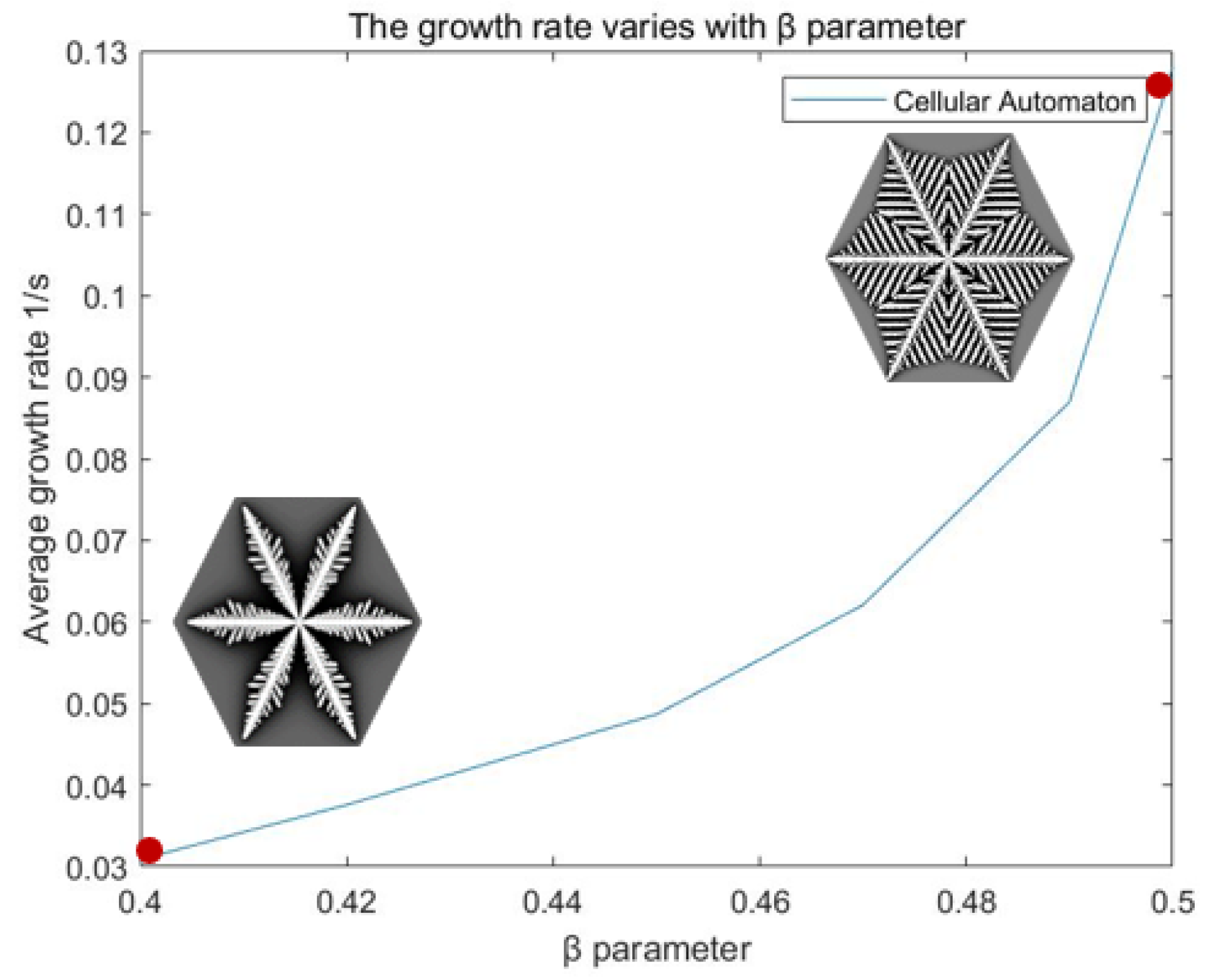
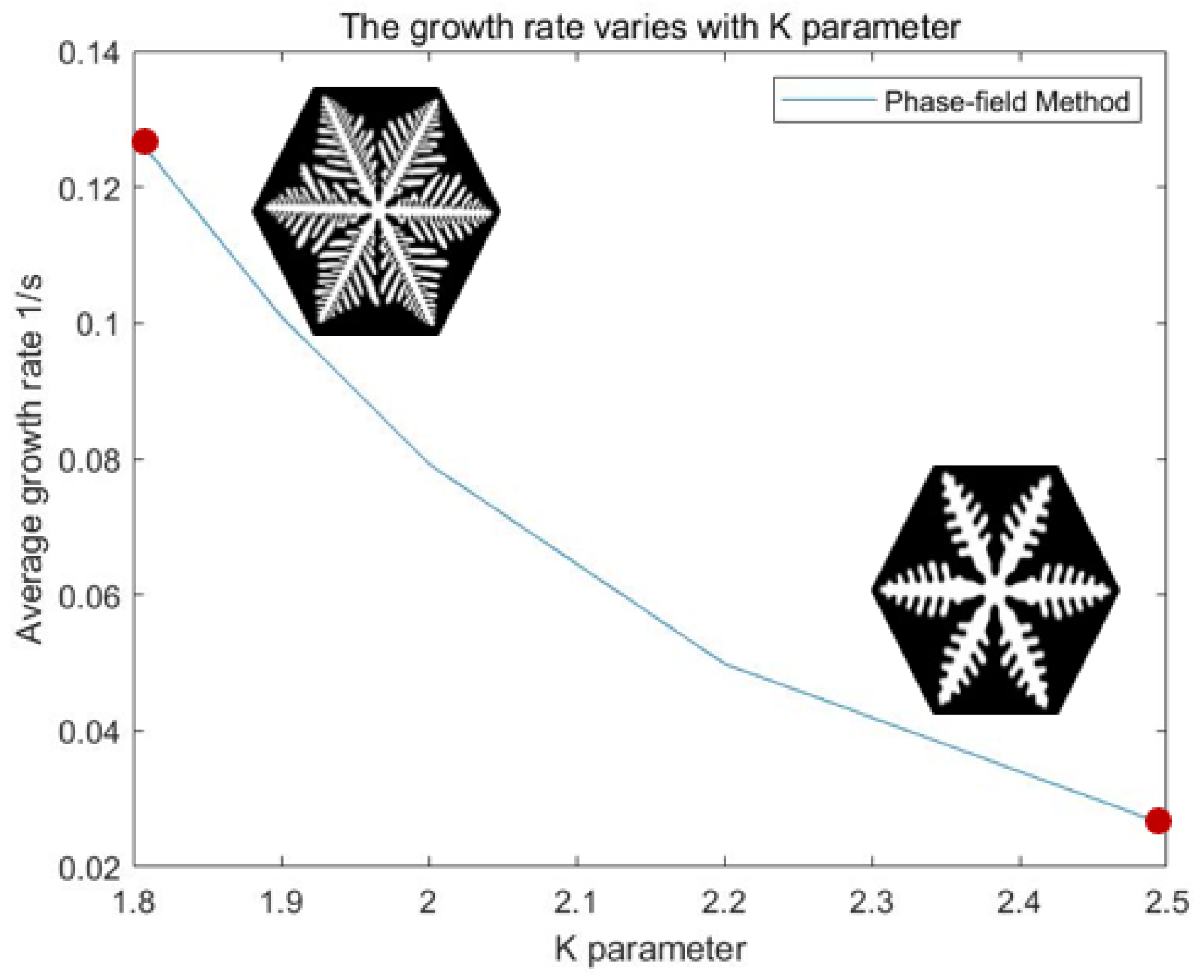
In addition to the classical snowflake morphologies simulation, the parameters of CA are considered to be interpreted physically by PF. The classical snowflake obtained above is taken as the benchmark case, and the two parameters of CA are finely adjusted to simulate different results. The parameters of PF are systematically compared to obtain the relationship with CA parameters. In the CA model, the environmental parameter γ is set to 0 and the morphologies of snowflakes do not change obviously when the β parameter is reduced from 4.9, and the growth rate of the secondary arm is slower than that of the primary arm. However, the average growth rate of snowflakes is significantly slower as shown in Figure 16. The vertical axis is normalized, and the horizontal axis is the discrete time of PF obtained from the previous time scaling factor multiplied by the number of iterations of CA. In the PF model, the growth rate also slows down when the dimensionless latent heat is increased from 1.8 to 2.5, and the morphologies are almost the same, as shown in Figure 17. It is concluded that the β parameter of CA and the K parameter in PF have qualitatively similar properties in this small range.
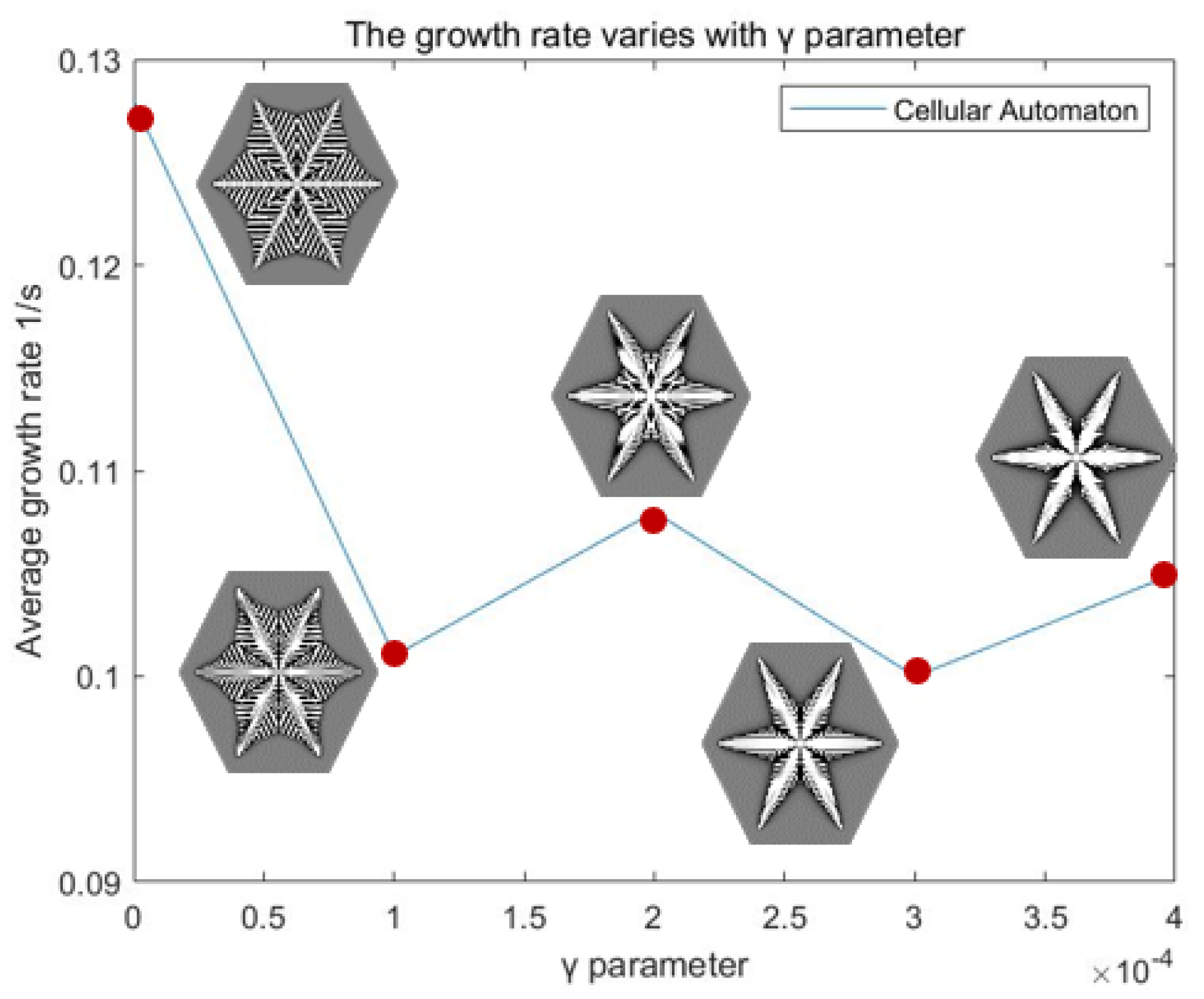
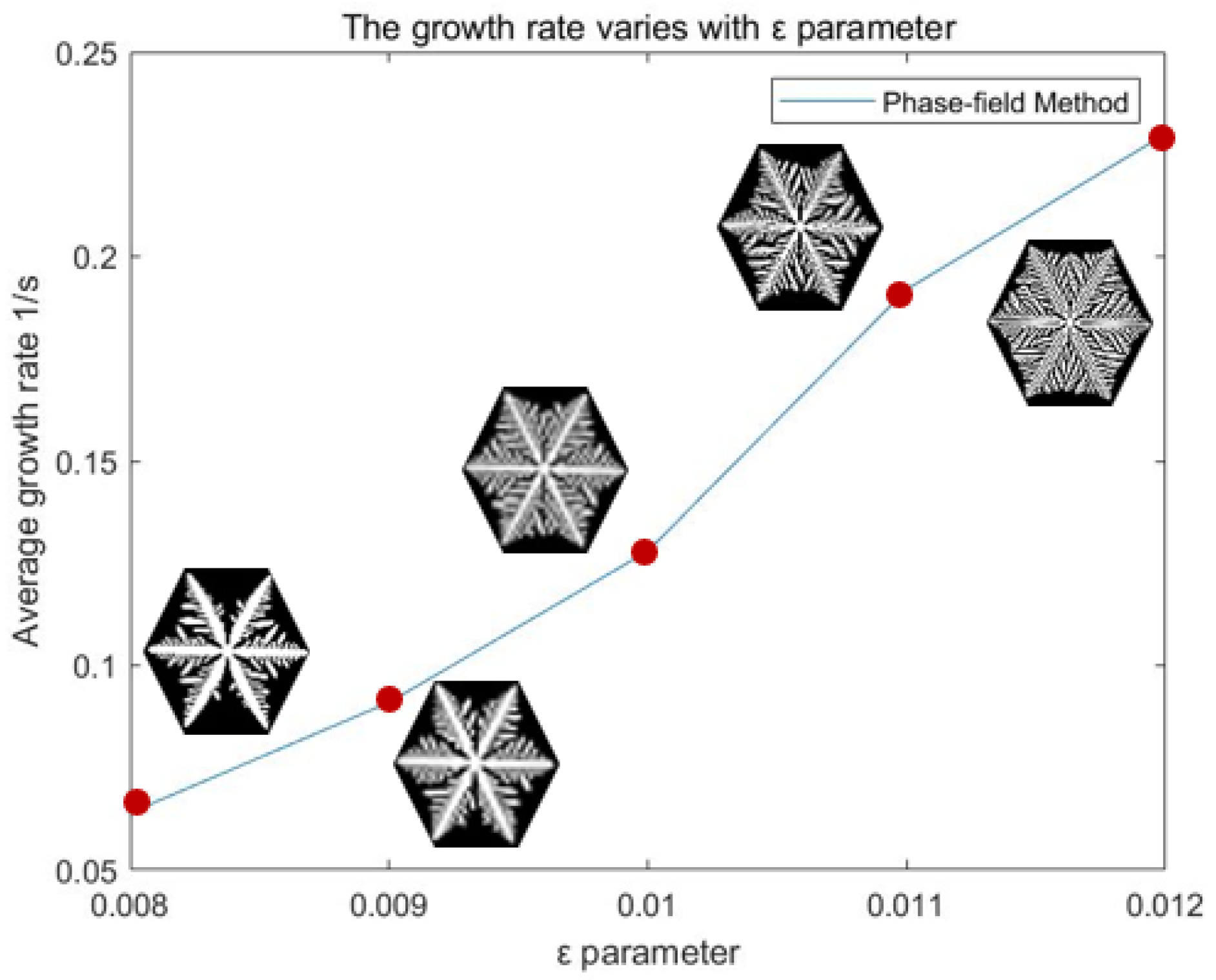
The γ parameter in CA represents the environment condition that improves the state value of the solid phase component with a constant value, while the situation is not considered in the PF model. The snowflake growth processes of the CA model with a fixed β parameter and an adjusted γ parameter are simulated in Figure 18. The average growth rates of different snowflake simulations are quite similar, while the morphologies of snowflakes show that the primary branches are gradually thickened and the growth of the secondary arms slow down. The γ parameter is mainly responsible for regulating the dendrite morphology of snowflakes according to the simulation results. In the PF model, the anisotropic parameter ε ¯ also affects the morphology of snowflakes. The mean anisotropic gradient energy coefficient of PF is adjusted with other parameters unchanged to obtain different snowflakes, as shown in Figure 19. Although the parameter ε ¯ has an influence on the growth rate of dendrites, the trend of the overall morphology is similar to the adjustment of the γ parameter. According to the detailed qualitative and partial quantitative verification and systematic comparison, the background parameter 𝛽 is related to the dimensionless latent heat K, and both parameter γ in CA and parameter ε ¯ in PF can affect the morphologies of snowflakes. Although the changes in these parameters do not correspond to each other perfectly due to the complex parameter coupling problems, they are indeed related qualitatively.
4. Conclusions

In this paper, the crystallization processes of water under different parameter values are simulated by CA and PF. PF is based on the derivation of the phase-field equation, and the simulation results need to be obtained by solving the partial differential equation. CA adopts the method of setting cellular rules and the iterative evolution of the cellular grid without considering the details of the physical mechanism. The two approaches describe the problem in different ways, and the number of model parameters is also different, but the snowflake patterns in some cases can be reproduced in both methods. Three classical snowflake forms are used to compare the parameters of the environment state description in the two methods. The similarity between iteration and time is that the snowflake grows with the increase in iteration or time in the CA model or the PF model, respectively, and the qualitative relationship between the parameters of CA and PF is found by systematic analysis. Although the equivalence does not fit perfectly between the two models, a relatively certain physical interpretation for CA is provided by the PF model. The dendrite formation process can be better understood by combining these two methods to explain the dendrite growth process from two perspectives and the idea of research is expected to be applied to other systems.

Author Contributions

Conceptualization, W.S., J.D. and J.A.; methodology, Y.D.; software, J.D.; validation, W.S. and C.Z.; formal analysis, C.Z.; investigation, Y.D. and J.A.; resources, W.S.; data curation, Y.D.; writing—original draft preparation, Y.D.; writing—review and editing, W.S.; visualization, J.D. and J.A.; supervision, W.S.; project administration, C.Z.; funding acquisition, W.S. All authors have read and agreed to the published version of the manuscript.

Funding

This research was funded by The National Natural Science Foundation of China, grant number 21878012.

Data Availability Statement

No new data were created or analyzed in this study. Data sharing is not applicable to this article.

Acknowledgments

The authors gratefully acknowledge the following institution for support: The National Natural Science Foundation of China (Grant No. 21878012). They also express their gratitude to the anonymous reviewers for their careful work and thoughtful suggestions that helped improve this paper substantially.

Conflicts of Interest

The authors declare no conflict of interest. The funders had no role in the design of the study, in the collection, analyses, or interpretation of data, in the writing of the manuscript, or in the decision to publish the results.

Appendix A

The parameters and corresponding descriptions in the PF method and the CA model are listed in Table A1.
Table A1. Symbol description.
SymbolDescription
P Order parameter
Φ Free energy functional
K Dimensionless latent heat
mTemperature function
T Dimensionless temperature
μSupercooling coefficient
T e Equilibrium temperature
θ Normal angle of the interface
F Double-well potential function
ε Anisotropic parameter gradient energy coefficient
ε ¯ Mean anisotropic gradient energy coefficient
δ Anisotropic strength
j Anisotropic modulus
τ Releasing time
γ Vertical growth parameter
β Background water density
X 0 Noise intensity
dtDiscrete time

References

  1. Han, Y.; Yang, T.; Chen, Y. A perspective on morphology controlled synthesis of powder by tuning chemical diffusion and reaction. Adv. Powder Technol. 2020, 31, 922–925. [Google Scholar] [CrossRef]
  2. Dornbusch, D.A.; Hilton, R.; Lohman, S.D.; Suppes, G.J. Experimental Validation of the Elimination of Dendrite Short-Circuit Failure in Secondary Lithium-Metal Convection Cell Batteries. J. Electrochem. Soc. 2014, 162, A262–A268. [Google Scholar] [CrossRef]
  3. Tao, R.; Bi, X.; Li, S.; Yao, Y.; Wu, F.; Wang, Q.; Zhang, C.; Lu, J. Kinetics Tuning the Electrochemistry of Lithium Dendrites Formation in Lithium Batteries through Electrolytes. ACS Appl. Mater. Interfaces 2017, 9, 7003–7008. [Google Scholar] [CrossRef]
  4. Liu, Q.C.; Xu, J.J.; Yuan, S.; Chang, Z.W.; Xu, D.; Yin, Y.B.; Li, L.; Zhong, H.X.; Jiang, Y.S.; Yan, J.M.; et al. Artificial Protection Film on Lithium Metal Anode toward Long-Cycle-Life Lithium-Oxygen Batteries. Adv. Mater. 2015, 27, 5241–5247. [Google Scholar] [CrossRef]
  5. Tu, Z.; Nath, P.; Lu, Y.; Tikekar, M.D.; Archer, L.A. Nanostructured Electrolytes for Stable Lithium Electrodeposition in Secondary Batteries. Acc. Chem. Res. 2015, 48, 2947–2956. [Google Scholar] [CrossRef] [PubMed]
  6. Cheng, X.B.; Zhang, R.; Zhao, C.Z.; Zhang, Q. Toward Safe Lithium metal Anode in Rechargeable Batteries: A review. Chem. Rev. 2017, 117, 10403–10473. [Google Scholar] [CrossRef]
  7. Nakaya, U. Snow Crystal: Natural and Artificial; Harvard University Press: Cambridge, MA, USA, 1954. [Google Scholar]
  8. Ball, P. Material witness: Close to the edge. Nat. Mater. 2016, 15, 1060. [Google Scholar] [CrossRef]
  9. Libbrecht, G. The physics of snow crystals. Prog. Phys. 2005, 68, 855–895. [Google Scholar] [CrossRef] [Green Version]
  10. Mason, B.J. Snow crystal, natural and man-made. Contemp. Phys. 1992, 33, 227–243. [Google Scholar] [CrossRef]
  11. Nelson, J. Growth mechanisms to explain the primary and secondary habits of snow crystals. Philos. Mag. A 2001, 81, 2337–2373. [Google Scholar] [CrossRef]
  12. Neumann, V. Theory of Self-Reproducing Automaton; University of Illinois Press: Champaign, IL, USA, 1966. [Google Scholar]
  13. Reiter, C.A. A local cellular model for snow crystal growth. Chaos Solut. Fractals 2005, 23, 1111–1119. [Google Scholar] [CrossRef]
  14. Liu, J.; Dai, J.; Han, C.; Zhang, J.; Ai, J.; Zhai, C.; Liu, X.; Sun, W. Simulation of the Crystallization Process based on Cellular Automaton—Snowflake Formation from Pure Water System. Comput. Aided Chem. Eng. 2020, 48, 187–192. [Google Scholar]
  15. Liang, L.; Qi, Y.; Xue, F.; Bhattacharya, S.; Harris, S.J.; Chen, L.-Q. Nonlinear phase-field model for electrode-electrolyte interface evolution. Phys. Rev. E 2012, 86, 051609. [Google Scholar] [CrossRef] [PubMed] [Green Version]
  16. Wang, S.-L.; Sekerka, R.; Wheeler, A.; Murray, B.; Coriell, S.; Braun, R.; McFadden, G. Thermodynamically consistent phase-field models for solidification. Phys. D Nonlinear Phenom. 1993, 69, 189–200. [Google Scholar] [CrossRef]
  17. Kobayashi, R. Modeling and numerical simulations of dendritic crystal growth. Phys. D Nonlinear Phenom. 1993, 63, 410–423. [Google Scholar] [CrossRef]
  18. Kim, S.G.; Kim, W.T.; Suzuki, T. Phase-field model for binary alloys. Phys. Rev. E 1999, 60, 7186–7197. [Google Scholar] [CrossRef]
  19. Chen, M.; Ou, Z.; Zhou, Y. Optimization of correlative parameters in numerical simulation of ice crystal growth by phase-field. J. Nanjing Univ. (Nat. Sci.) 2014, 50, 873–882. [Google Scholar]
  20. Demange, G.; Zapolsky, H.; Patte, R.; Brunel, M. A phase field model for snow crystal growth in three dimensions. npj Computat. Mater. 2017, 3, 15. [Google Scholar] [CrossRef] [Green Version]
  21. Barrett, J.; Garcke, H.; Nürnberg, R. Numerical computations of faceted pattern formation in snow crystal growth. Phys. Rev. E 2012, 86, 011604. [Google Scholar] [CrossRef] [Green Version]
  22. Akyurt, M.; Zaki, G.; Habeebullah, B. Freezing phenomena in ice–water systems. Energy Convers. Manag. 2002, 43, 1773–1789. [Google Scholar] [CrossRef]
  23. Godunov, S.; Bohachevsky, I. Finite difference method for numerical computation of discontinuous solutions of the equations of fluid dynamics. Mat. Sb. 1959, 47, 271–306. [Google Scholar]
Figure 1. The neighbors of the CA model.
Processes 10 02337 g001
Figure 2. The rules of the CA model.
Processes 10 02337 g002
Figure 3. Simulation block diagram of the CA model.
Processes 10 02337 g003
Figure 4. Water phase diagram [22].
Processes 10 02337 g004
Figure 5. A schematic node-ordering representation for a two-dimensional finite-difference grid [23].
Processes 10 02337 g005
Figure 6. Snowflake simulation of the CA model.
Processes 10 02337 g006
Figure 7. Morphology of snowflakes with a different β parameter.
Processes 10 02337 g007
Figure 8. Morphology of snowflakes with a different γ parameter.
Processes 10 02337 g008
Figure 9. PF of snowflake growth.
Processes 10 02337 g009
Figure 10. Morphology of snowflakes with a different ε ¯ parameter.
Processes 10 02337 g010
Figure 11. CA and PF simulate classic snow pattern 1.
Processes 10 02337 g011
Figure 12. CA and PF simulate hexagonal snow patterns.
Processes 10 02337 g012
Figure 13. CA and PF simulate classic snow pattern 2.
Processes 10 02337 g013
Figure 14. Snowflake growth data acquisition.
Processes 10 02337 g014
Figure 15. Snowflake growth speed and boundary length of the PF and CA methods.
Processes 10 02337 g015
Figure 16. The growth rate varies with the β parameter by CA.
Processes 10 02337 g016
Figure 17. The growth rate varies with the K parameter by PF.
Processes 10 02337 g017
Figure 18. The growth rate varies with the γ parameter by CA.
Processes 10 02337 g018
Figure 19. The growth rate varies with the ε ¯ parameter by PF.
Processes 10 02337 g019
Table 1. PF parameters [17].
ParameterDescriptionValue
τ Releasing time0.0003 s
ε ¯ Mean anisotropic gradient energy coefficient0.01 J m−2
K Dimensionless latent heat1.8
δ Anisotropic strength0.02
j Anisotropic modulus6.0
μSupercooling coefficient10.0
α Temperature coefficient 0.9
T e Equilibrium temperature1.0 K
θ 0 Initial angle0.5
X 0 Noise intensity0.01
Publisher’s Note: MDPI stays neutral with regard to jurisdictional claims in published maps and institutional affiliations.