Article

The Optimization of Machining Parameters on Cutting Force during Orthogonal Cutting of Graphite/Polymer Composites

School of Mechanical and Automotive Engineering, Guangxi University of Science and Technology, Liuzhou 545006, China
*
Authors to whom correspondence should be addressed.
Processes 2022, 10(10), 2096; https://doi.org/10.3390/pr10102096
Submission received: 10 September 2022 / Revised: 8 October 2022 / Accepted: 14 October 2022 / Published: 16 October 2022
(This article belongs to the Section Materials Processes)

Abstract

:
Graphite/polymer composites are brittle materials, and tool wear, which has a significant impact on the quality of the machined surface of the material, is very serious during the cutting process. In general, the magnitude of the cutting force directly affects the tool wear; the larger the cutting force, the more severe the tool wear, which in turn affects the machined surface quality of graphite/polymer composites. Therefore, in this study, the effects of machining parameters on cutting forces during orthogonal cutting of graphite/polymer composites were investigated using single-factor and multifactor experiments with cutting speed, cutting thickness, tool rake angle, and rounded edge radius as influencing factors, and the parameters were optimized. The obtained results showed that reducing the cutting thickness and increasing the tool rake angle would significantly reduce the cutting force. During the orthogonal cutting process, when the tool had a small edge radius, the cutting force along the cutting direction was significantly larger than the cutting force along the vertical direction, and as the rounded edge radius increased, the cutting force in the vertical direction exceeded the cutting force in the cutting direction. Finally, the significance of the effect of different machining parameters on the cutting forces was analyzed using analysis of variance (ANOVA). The obtained results showed that the cutting speed, cutting thickness, tool rake angle, and rounded edge radius were extremely significant for the cutting forces along the cutting direction as well as in the vertical direction during orthogonal cutting of graphite/polymer composites.

1. Introduction

Graphite/polymer composites are brittle materials that have been widely used in the petrochemical [1], mechanical [2], electronic [3], nuclear [4,5], national defense [6], and powder metallurgy [7,8] industries. With the development of modern science and technology and industry, the application field of graphite parts is still expanding and plays an important role in the national economy. In practical applications, a significant portion of graphite parts needs to be machined to meet design requirements. Therefore, determining how to improve their machining performance has an important impact on the application of graphite products. At present, many researchers have studied various aspects of the machining properties of graphite and its composites.
Wang et al. [9] used orthogonal cutting experiments to study the chip formation process of graphite electrodes and the appearance of the machined surface. The results showed that the chips from graphite electrodes were significantly different from the traditional metal chips such as aluminum alloy. The former was unable to form continuous band-like chips. In addition, the increase in cutting thickness led to different material removal methods. When the cutting thickness was small, the material removal method was mainly fragmented removal, and when the cutting thickness was increased to a certain extent, the chips were mainly removed in blocks with obvious cracks. Finally, there were many randomly distributed pits on the machined surface. It can be seen that the material removal method of graphite material during the machining process is significantly different from the removal method of common material. Zhou et al. [10] found that reducing the cutting depth could significantly improve the quality of machined surface during the machining process of graphite. Schroeter et al. [11] found in a study on the milling performance of graphite electrodes that it could produce serious edge collapse defects at the edges of the machined surface of the graphite electrode. The size of the edge chipping is influenced by the process parameters, with the depth of cut having the most significant effect. Huo et al. [12] studied the effects of feed speed, cutting speed, and axial cutting depth on graphite machining surface quality by combining experimental design with ANOVA. The results showed that the feed rate had the greatest effect on the surface roughness of graphite machining. Sanchez et al. [13] found that cutting speed and feed rate had the most significant effect on the machined surface quality of graphite electrodes, and that lower machined surface roughness was obtained when higher cutting speed and lower feed rate were used. Zeilmann et al. [14] investigated the machined surface roughness of graphite electrodes under different milling parameters using an orthogonal design of experiments, and the results showed that the lowest machined surface roughness could be obtained at a cutting speed of 400 m/min and a feed rate of 0.04 mm per tooth when using diamond-coated tools.
In addition, tool wear is also a popular topic in the study of graphite/polymer composites because tool wear, which has a significant impact on the quality of the machined surface of the material, is very serious during the cutting process of graphite/polymer composites. In general, the magnitude of the cutting force directly affects the tool wear; the larger the cutting force, the more severe the tool wear, which in turn affects the quality of machined surface of graphite/polymer composites. Moreover, different machining parameters can have a great impact on the magnitude of the cutting force.
The effect of different machining parameters on cutting forces is one of the main elements in the analysis and study of material machining performance, and the systematic analysis of its variation pattern helps researchers to better investigate the cutting performance of materials. For the machining of graphite/polymer composites, the analysis of cutting forces under different machining parameters will help to reduce tool wear during machining and thus improve the machining quality and productivity of the parts. However, there is still a lack of research on the effect of machining parameters on cutting forces.
Therefore, this study systematically analyzed the variation trend of the cutting force under different machining parameters. In this paper, the effect of different machining parameters on the machined surface quality was first analyzed by single-factor experiments. Then, the comprehensive effects of cutting speed, cutting thickness, tool rake angle, and rounded edge radius on the machined surface quality were investigated by multifactor experiments. Finally, the significance of different machining parameters on the cutting force was analyzed by ANOVA.

2. Experimental Method

Graphite/polymer composites are brittle materials and the cutting force greatly fluctuates during the cutting process. Thus, it is difficult to obtain the best optimization. The reliability of the results is not sufficient if only one optimization method is used. To obtain a reliable optimization scheme, several different optimization methods were selected. Finally, the best combination of parameter was selected.
To explore the influence of the changes in various machining parameters on the cutting force, this study first performed a single-factor experiment. However, during the actual cutting process, the cutting force is often affected by the machining parameters. If only a single-factor experiment is used, it cannot fully reflect the influence of machining parameters on the cutting force. To obtain the optimal optimization of parameter of the cutting force, it is necessary to analyze the cutting force with a multifactor method.

2.1. Experimental Design and Results

Single-Factor Experiments

In the single-factor experiments, four series of experiments were designed to study the influence of the tool rake angle, cutting thickness, cutting speed, and rounded edge radius on the cutting force.
As shown in Figure 1, the cutting experiment was performed on a BC6063B planer. The KISTLER dynamometer was used to measure the force in real time during the machining process using various cutting parameters. Since the cutting method was orthogonal, only the forces in the cutting direction and the vertical direction, expressed as FH and FV, respectively, were collected during the cutting process. The dynamometer was placed on the planer table during the cutting process and the workpiece was clamped on the gauge by means of a self-designed fixture. The experimental materials were purchased from the market, and the main mechanical properties are shown in Table 1. The tool material used in the experiment was high-speed steel.
Five sets of comparative experiments were performed to explore the trend of the cutting forces during the cutting process of graphite/polymer composites with different tool rake angles. The cutting speed was 5 m/min, the cutting thickness was 0.1 mm, the rounded edge radius was 10 μm, and the tool rake angles were −20°, −10°, 0°, 10°, 20°.
Five sets of experiments were conducted to research the trend of the cutting forces at different cutting thicknesses during graphite cutting, in which the tool rake angle was 10°, the rounded edge radius was 10 μm, the cutting speed was 5 m/min and the cutting thickness was 0.05, 0.10, 0.15, 0.20, and 0.30 mm.
Five sets of experiments were performed to study the trend of the cutting force at different cutting speeds during graphite cutting, in which the tool rake angle was 10°, the rounded edge radius was 10 μm, the cutting speed was 5 m/min and the cutting thickness was 0.10 mm. The cutting speeds were 3, 5, 7, 10, and 12 m/min.
Five sets of experiments were conducted to understand the trend of the cutting force at different tool radii during graphite cutting. The tool rake angle was 10°, the cutting thickness was 0.1 mm, the cutting speed was 5 m/min, and the rounded edge radii were 10, 30, 50, 70, and 90 μm.

2.2. Multifactor Experiments

During the cutting process, the main factors affecting the cutting force include the cutting speed (vc), cutting thickness (hD), tool rake angle (γo), and rounded edge radius (rε). The specific values are shown in Table 2.
The L9(34) orthogonal table was used to carry out the cutting experiment. The cutting experiment was performed on the BC6063B planer, and the cutting force was tested by the KISTLER dynamometer. Because the cutting force greatly fluctuates, the average cutting force during the cutting process is used as the cutting force under this parameter combination. To ensure the accuracy of the experiment, every parameter combination was used three times, and the average value was taken as the cutting force under the parameter combination. In addition, because the experimental process uses four factors, the L9(34) orthogonal table has no empty column for the error column. Therefore, to perform ANOVA, it is necessary to repeat the experiment for every parameter combination. The experiment was repeated according to the previous experiment. The steps were repeated three times in total. Each parameter combination requires a total of 9 experiments. The specific test parameter combinations and the results of the corresponding cutting force are shown in Table 3.

3. Analysis and Discussion of Experimental Results

3.1. Analysis and Discussion of Single-Factor Experimental Results

The single-factor experiments were divided into four parts. The effects of tool rake angle, cutting thickness, cutting speed, and rounded edge radius on cutting force were studied in experiments. The analysis and discussion of the experimental results are as follows.

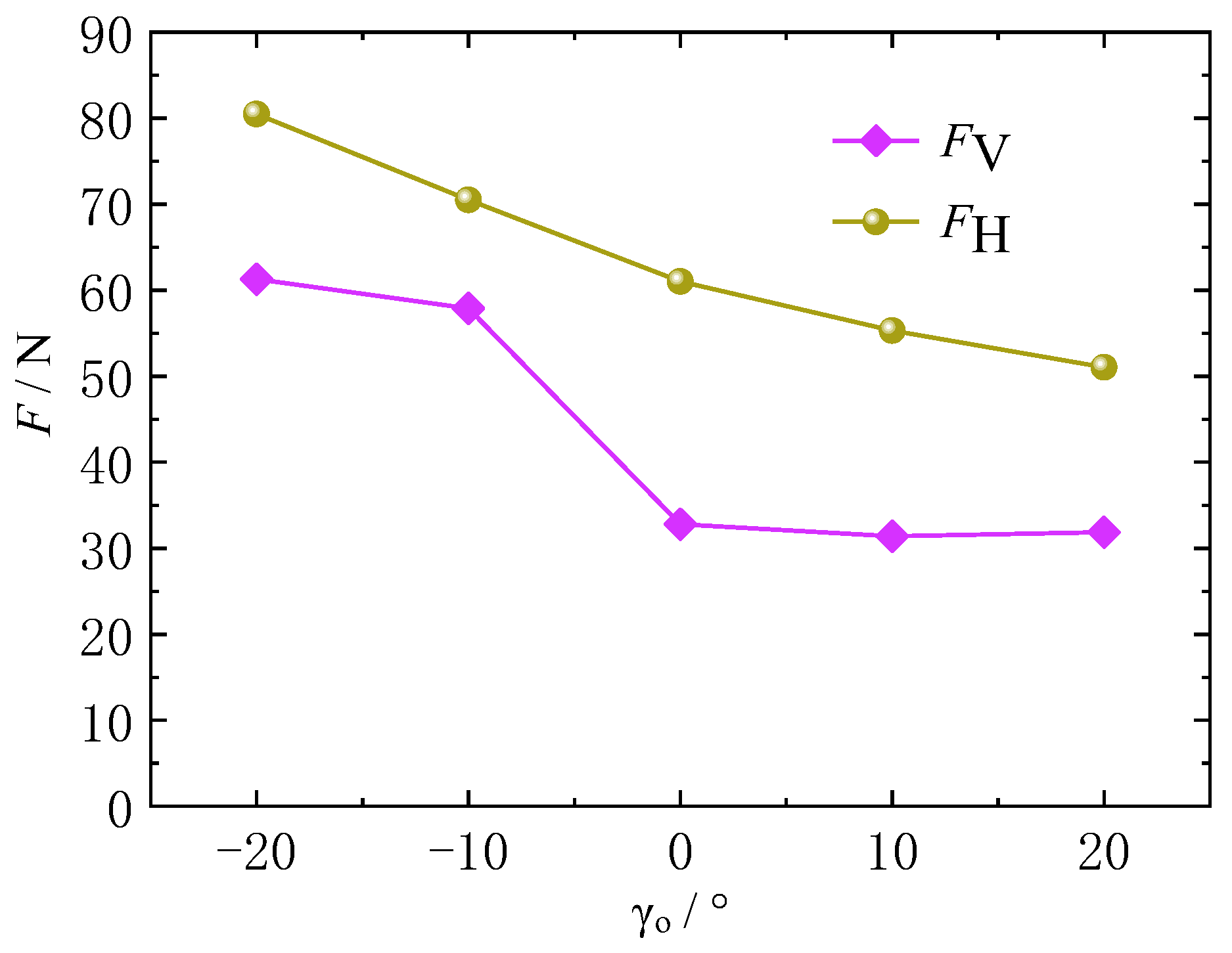
3.1.1. Influence of Tool Rake Angle on Cutting Force

When the cutting speed is 5 m/min, the rounded edge radius is 10 μm, and the cutting thickness is 0.1 mm, the variation trend of the average cutting force during the cutting process under different tool rake angles is shown in Figure 2, where FH represents the cutting force in the cutting direction, and FV represents the cutting force in the vertical direction. From the figure, it can be seen that the cutting force shows a significant decrease with the increase in the tool rake angle, which indicates that the use of a larger tool rake angle can significantly reduce the cutting force during the cutting process of graphite/polymer composites, which in turn is beneficial to reduce tool wear.

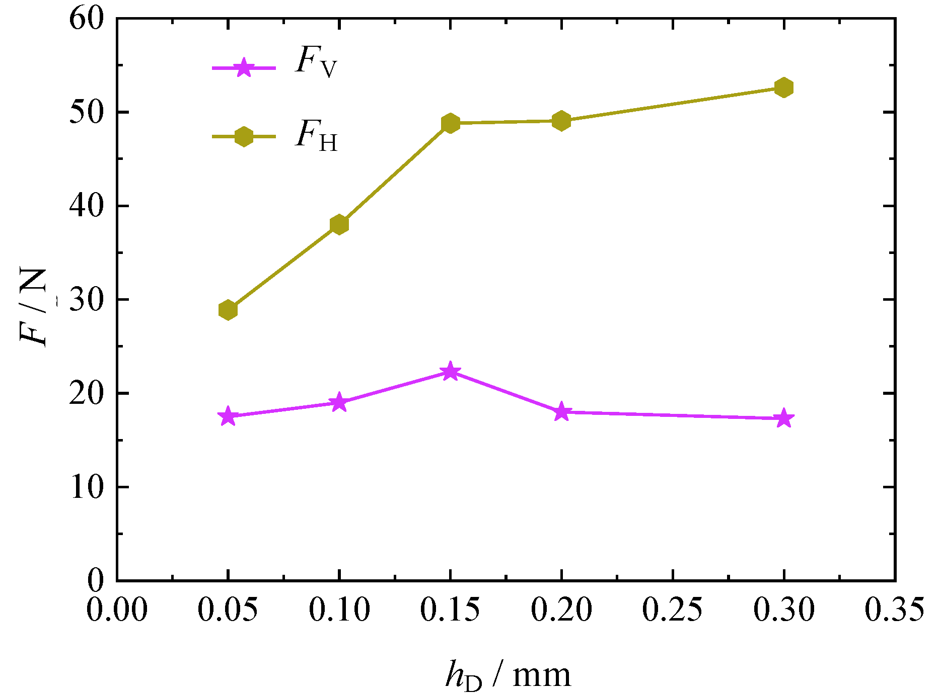
3.1.2. Impact of Cutting Thickness on Cutting Force

The trends of the average cutting force at different cutting thicknesses when the tool rake angle is 10°, the rounded edge radius is 10 μm, and the cutting speed is 5 m/min are shown in Figure 3. It can be seen that with the increase in the cutting thickness, the cutting force in the vertical direction has only a small amplitude fluctuation, without any other clear trend of change. The average cutting force along the cutting speed direction shows a significant upwards trend with increasing cutting thickness. This phenomenon is caused by the fact that the material in the cutting layer has stronger shear resistance with the increasing cutting thickness. Figure 4 shows that reducing the cutting thickness can significantly reduce the cutting force in the cutting direction during the cutting of graphite/polymer composites.

3.1.3. Influence of Cutting Speed on Cutting Force

The change in the cutting speed has a significant impact on the cutting performance of the material. To a certain extent, the change in the cutting speed can reduce the cutting force and prolong the tool life. When the tool rake angle is 10°, the cutting thickness is 0.1 mm, and the rounded edge radius is 10 μm, the average cutting force of graphite/polymer composites at different cutting speeds is shown in Figure 4. In addition, it can be seen from the figure that the cutting force along the vertical direction slightly increases with increasing cutting speed. The cutting force along the cutting direction also shows an upwards trend with increasing cutting speed, but the rising range is slightly larger than that along the vertical direction.

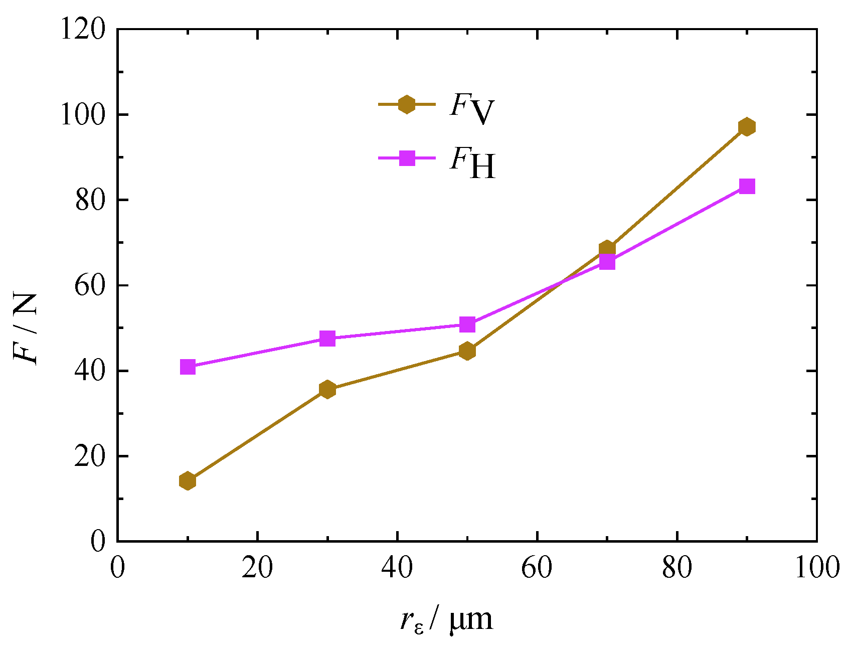
3.1.4. Effect of Rounded Edge Radius on Cutting Force

When the tool rake angle is 10°, the cutting thickness is 0.1 mm, and the cutting speed is 5 m/min, the cutting force of the graphite/polymer composite under different rounded edge radii is shown in Figure 5. It can be clearly seen that the cutting force along the cutting direction and the vertical direction significantly increases with increasing rounded edge radius. The rising range of the cutting force in the vertical direction is clearly larger than that in the cutting direction. Compared with the changing trend of the cutting force under other machining parameters, it can be seen that the cutting force under different rounded edge radii has a unique changing trend. When the rounded edge radius is small, the cutting force along the cutting direction is clearly larger than that in the vertical direction. With the increase in the rounded edge radius, the cutting force in the vertical direction exceeds the cutting force along the cutting direction because of its greater increase.

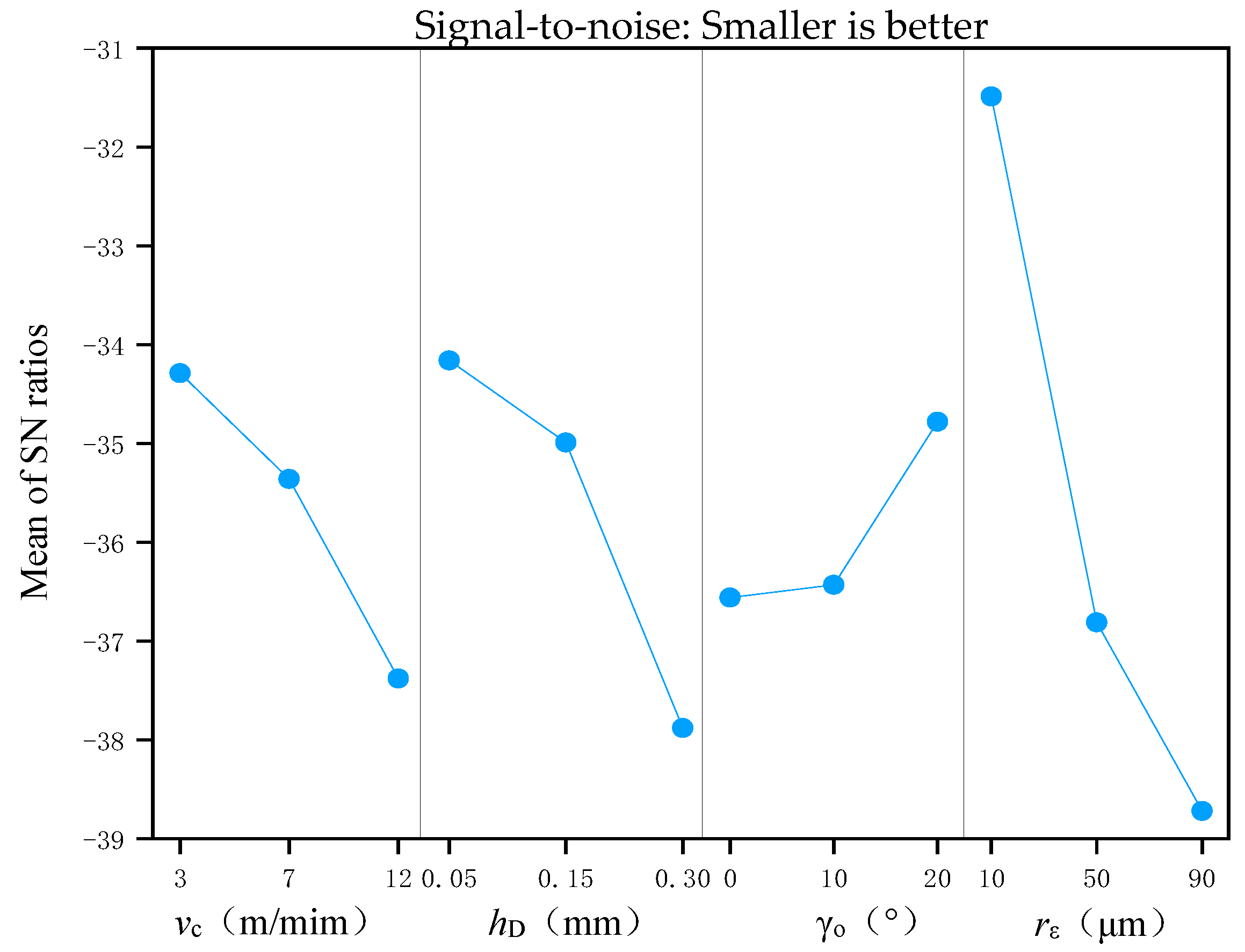
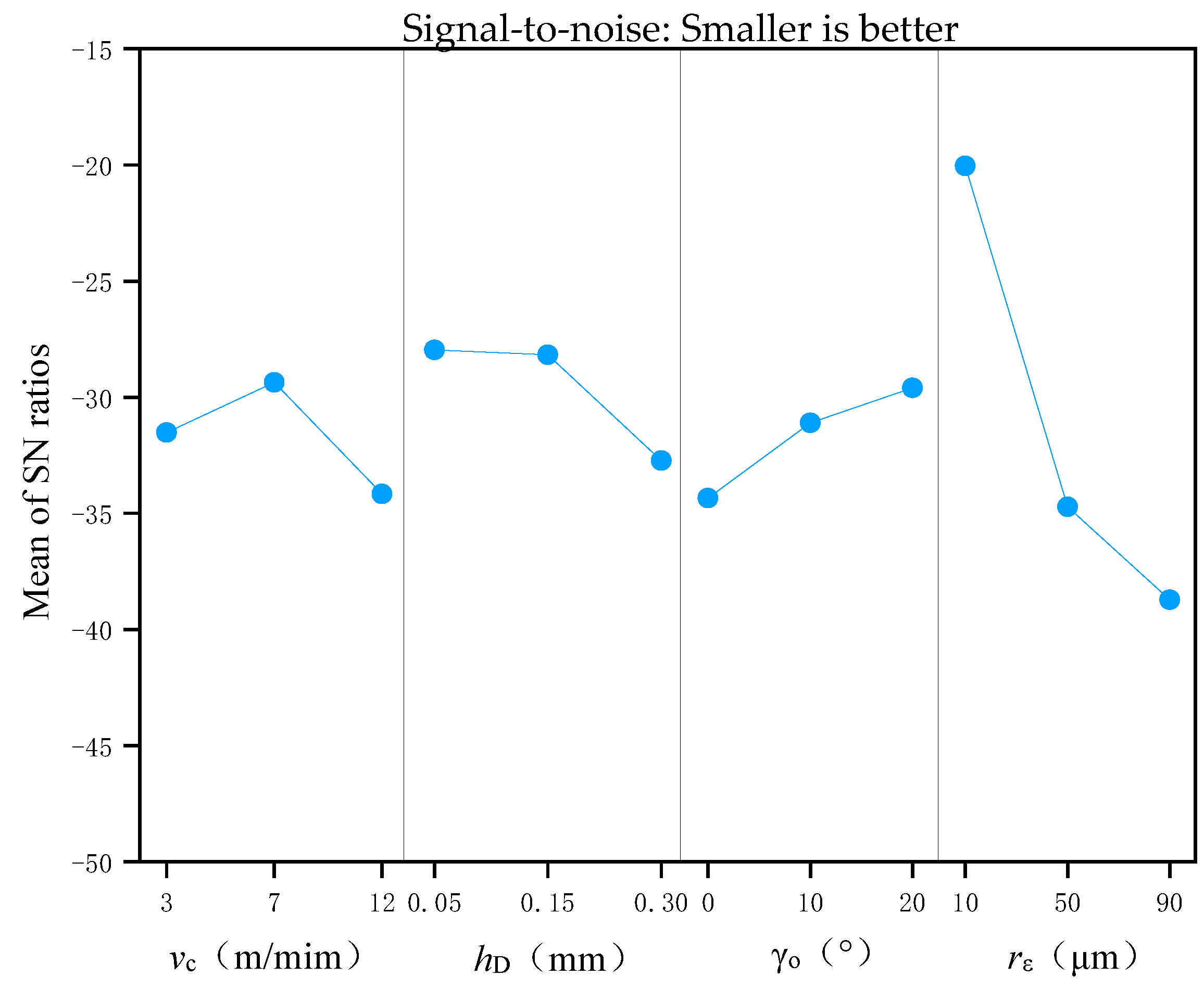
3.2. Brief Introduction of Signal-to-Noise Ratio

In this study, the signal-to-noise ratio method was used to analyze the results of multifactor experiments. The signal-to-noise ratio is an optimization method of parameter proposed by Dr. Taguchi, Japan, which has been widely used in the field of optimization of machining parameters [15,16,17,18]. In this section, the signal-to-noise ratio method is used to analyze the cutting force under the machining parameters.
There are three output methods of the signal-to-noise ratio. The first is the bigger-the-better characteristic. The second characteristic is to try to be as close as possible to the target value. The third is the smaller-the-better characteristic. The cutting force of graphite/polymer composites is expected to be as small as possible. It belongs to the smaller-the-better characteristic [19,20]. Its method of calculation is shown in Formula (1) [17]:
η = 10 log 10 1 n i = 1 n y i 2

3.3. Signal-to-Noise Ratio under Different Machining Parameters

According to the measured data in Table 3, the signal-to-noise ratio of the cutting force of graphite/polymer composites under different machining parameters is solved using Formula (2). When the cutting speed is 3 m/min, the calculation process of the cutting force signal-to-noise ratio of experiment 1# along the cutting direction is as follows:
η = 1 3 10 log 10 31.6 2 10 log 10 54.2 2 10 log 10 84.3 2 = 34.40
When the cutting speed is 3 m/min, the calculation process of the cutting force signal-to-noise ratio of experiment 1# along the vertical direction is as follows:
η = 1 3 10 log 10 22 2 10 log 10 33.6 2 10 log 10 81.4 2 = 31.86
Similarly, the signal-to-noise ratio of the cutting force under other machining parameters can be obtained. In addition, to draw the signal-to-noise ratio histogram, the average value of repeated experiments was taken as the signal-to-noise ratio under this machining parameter. The calculation results are shown in Table 4.
The histogram of the signal-to-noise ratio of the cutting force along the cutting direction under different machining parameters is shown in Figure 6. According to the analysis method of the signal-to-noise ratio, the parameter corresponding to the maximum signal-to-noise ratio is selected as the optimal parameter. Therefore, the combination of machining parameters for the minimum cutting force along the cutting direction during the orthogonal cutting process of graphite/polymer composites can be intuitively obtained from the figure. Namely, the cutting speed is 3 m/min, the cutting thickness is 0.05 mm, the rake angle of the tool is 20°, and the rounded edge radius is 10 μm.
The histogram of the signal-to-noise ratio of the cutting force along the vertical direction under different machining parameters is shown in Figure 7. According to the analysis method of Figure 6, the machining parameter combination of the minimum cutting force in the vertical direction can be obtained from the figure. Namely, the cutting speed is 7 m/min, the cutting thickness is 0.05 mm, the tool rake angle is 20°, and the rounded edge radius is 10 μm.
Figure 6 and Figure 7 present the optimal machining parameters for the graphite/polymer composite to obtain the minimum cutting force during orthogonal cutting. However, the most important index to evaluate the machinability should be the machined surface roughness for the machining of graphite/polymer composites. Therefore, the optimal machining parameters for cutting forces obtained above need to be analyzed together with the machining parameters for minimizing the roughness of the machined surface, so that the cutting forces can be reduced as much as possible on the basis of the quality of the machined surface.
Figure 8a shows the shape of the machined surface under the machining parameters optimized by multi-factor experiments. It can be seen that there are some tiny concavities on the machined surface. Figure 8b shows the machined surface morphology of graphite/polymer composites without optimizing machining parameters. The number of concavities in Figure 8a is much less and the size is significantly smaller than that in Figure 8b. Obviously, the quality of machined surface in Figure 8a is much better than that in Figure 8b, which shows that the method of optimizing machining parameters by multi-factor test is feasible.

3.4. Analysis of Variance

In the abovementioned discussion, the machining parameters based on the minimum cutting force were obtained using the signal-to-noise ratio analysis method. However, the first challenge is obtaining the lowest roughness of machined surface during the process of graphite/polymer composites. Therefore, machining is usually not performed with the optimal parameters obtained above. In this case, it is very important to determine the significance of the influence of different machining parameters on the cutting force. ANOVA is an effective method to study the influence degree of different machining parameters on the evaluation index, and the method of signal-to-noise ratio combined with ANOVA has been widely used in the field of parameter optimization [18,21,22,23]. This section uses ANOVA to analyze the significance of the influence of different machining parameters on the cutting force.
First, the cutting force FH along the cutting direction is analyzed. According to the test results in Table 3, data processing was first performed according to the steps of ANOVA, and the results of processing are shown in Table 5.
In Table 5, y i and y · are the sum of cutting forces of the same parameter combination under different groups of tests and the sum of all test cutting forces, respectively.
The calculation results of other relevant data are shown below, and the results after solving are shown in Table 5. The calculation process of k g 1 is as follows [23,24]:
k g 1 = 89.4 + 165.2 + 254.7 = 509.3
Similarly, k g 2 and k g 3 can be calculated in the same way. CT is the correction number and the solution process is as follows [23,24]:
C T = y · 2 3 × 9 = 118551.1
The solution process of the sum of squared deviations in column g is [23,24]:
S S g = k g 1 2 + k g 2 2 + k g 3 2 / 3 × 3 C T
The solution process of the total deviation sum of squares is as follows [23,24]:
S S T = i = 1 n j = 1 k y i j 2 C T = 135817.8 118551.1 = 17266.7
The above mentioned solution results are listed in the ANOVA table, and the relevant degrees of freedom, mean square, and F value were solved according to the steps of ANOVA. According to the statistical method, “ns”, “*”, and “**” represent insignificant, significant, and extremely significant influences, respectively. The specific results of ANOVA are shown in Table 6. It can be seen from the table that the cutting speed, cutting thickness, tool rake angle, and rounded edge radius are extremely significant to the cutting force along the cutting direction during the orthogonal cutting process of graphite/polymer composites. The most influential machining parameter is the rounded edge radius, followed by the cutting thickness, cutting speed, and the tool rake angle.
Similarly, the data processing results for cutting forces in the vertical direction can be obtained. The results are shown in Table 7.
The ANOVA of the cutting force along the vertical direction is shown in Table 8. It can be seen from the table that cutting speed, cutting thickness, tool rake angle, and rounded edge radius have an extremely significant influence on the vertical cutting force during the orthogonal cutting process of graphite/polymer composites. The most influential machining parameter is the rounded edge radius, followed by the cutting speed, tool rake angle, and the cutting thickness.

4. Conclusions

The effects of machining parameters on the cutting force were studied by single-factor and multifactor experiments during the orthogonal cutting process of graphite/polymer composites to minimize the cutting force on the basis of good quality of the machined surface. The specific results are as follows:
(1)
The change in machining parameters can significantly affect the cutting force. When the tool rake angle increased from −20° to 20°, the cutting force reduced by 25%. When the cutting thickness increased from 0.05 to 0.30 mm, the cutting force increased by 63.9%. When the cutting speed increased from 3 to 12 m/min, the cutting force increased by 32.4%. When the rounded edge radius increased from 10 to 90 μm, the cutting force increased by 195.3%. Mostly, the cutting force along the cutting direction is significantly greater than the vertical cutting force. However, when the rounded edge radius exceeds 65 μm, the cutting force in the vertical direction will exceed the cutting force in the cutting direction.
(2)
The parameter combination of the minimum cutting force is obtained through the analysis of the signal-to-noise ratio of the cutting force. Namely, the parameter combination of the minimum cutting force along the cutting direction is that the cutting speed is 3 m/min, the cutting thickness is 0.05 mm, the tool rake angle is 20°, and the rounded edge radius is 10 μm. The parameter combination of the minimum cutting force in the vertical direction is that the cutting speed is 7 m/min, the cutting thickness is 0.05 mm, the tool rake angle is 20°, and the rounded edge radius is 10 μm. Considering the effect of cutting speed on cutting force, the recommended combination of machining parameters during the actual cutting process is that the cutting speed is 3 m/min, the cutting thickness is 0.05 mm, the tool rake angle is 20°, and the rounded edge radius is 10 μm.
(3)
The ANOVA showed that the tool rake angle, cutting thickness, cutting speed, and rounded edge radius had extremely significant effects on the cutting force along the cutting direction and the cutting force in the vertical direction during the orthogonal cutting process of graphite/polymer composites.

Author Contributions

W.W.: Conceptualization, investigation, software, writing—original draft preparation; D.Y.: formal analysis, methodology, project administration, writing and editing; R.W.: project administration, resources; F.W.: software, writing—review and editing; M.L.: writing—review and editing, project administration. All authors have read and agreed to the published version of the manuscript.

Funding

This work was supported by the National Natural Science Foundation of China (no. 52165055), Science and Technology Project of Guangxi, China (no. GK AD19245149).

Data Availability Statement

All data used to support the findings of this study are included within the article.

Acknowledgments

This work was supported by the School of Mechanical and Automotive Engineering, Guangxi University of Science and Technology.

Conflicts of Interest

The authors declare that they have no conflict of interest regarding the publication of this paper.

References

  1. Pouya, J.; John, K.; Majid, B. Development of novel plate heat exchanger using natural graphite sheet. Int. J. Heat Mass Transf. 2019, 131, 1205–1210. [Google Scholar]
  2. Li, D.L. Mixed graphite cast iron for automotive exhaust component applications. China Foundry 2017, 14, 519–524. [Google Scholar] [CrossRef] [Green Version]
  3. Chen, Z.; Liu, Y.; Zhang, Y.; Shen, F.; Yang, G.; Wang, L.; Zhang, X.; He, Y.; Luo, L.; Deng, S. Ultrafine layered graphite as an anode material for lithium ion batteries. Mater. Lett. 2018, 229, 134–137. [Google Scholar] [CrossRef]
  4. Pozzetto, S.; Capone, M.; Cherubini, N.; Cozzella, M.L.; Dodaro, A.; Guidi, G. Proposal of a prototype plant based on the exfoliation process for the treatment of irradiated graphite. Nucl. Eng. Technol. 2019, 52, 797–801. [Google Scholar] [CrossRef]
  5. Pavlyuk, A.O.; Bespala, E.V.; Kotlyarevskii, S.G.; Zagumennov, V.S.; Zakharova, E.V.; Volkova, A.G.; Rodygina, N.I. Electrochemical Decontamination of Irradiated Nuclear Graphite of Uranium-Graphite Nuclear Reactors. At. Energy 2020, 128, 24–29. [Google Scholar] [CrossRef]
  6. Yao, W.J.; Fan, L.; Liu, G.Y. Advance in Properties of Graphene and Graphene/Metal Layered Composite After Irradiation Damage. Rare Met. Mater. Eng. 2019, 48, 3130–3135. [Google Scholar]
  7. Temel, V.; Aykut, C. An investigation on wear behavior of Cu-graphite nanocomposites prepared by flake powder metallurgy. Ind. Lubr. Tribol. 2017, 69, 8–14. [Google Scholar]
  8. Suriyaprakash, M.; Nallusamy, M.; Kiran, K.; Rajkumar, S. Investigation of mechanical properties on Mg/TiC/graphite hybrid composites fabricated by powder metallurgy techniques. Mater. Today Proc. 2022, 62, 2256–2260. [Google Scholar] [CrossRef]
  9. Wang, C.; Zhou, L.; Hao, F.U.; Hu, Z. High speed milling of graphite electrode with endmill of small diameter. Chin. J. Mech. Eng. 2007, 20, 27–31. [Google Scholar] [CrossRef]
  10. Zhou, L.; Wang, C.Y.; Qin, Z. Investigation of Chip Formation Characteristics in Orthogonal Cutting of Graphite. Mater. Manuf. Process. 2009, 24, 1365–1372. [Google Scholar] [CrossRef]
  11. Schroeter, R.B.; Kratochvil, R.; de Oliveira Gomes, J. High-speed finishing milling of industrial graphite electrodes. J. Mater. Process. Technol. 2006, 179, 128–132. [Google Scholar] [CrossRef]
  12. Huo, D.; Lin, C.; Dalgarno, K. An experimental investigation on micro machining of fine-grained graphite. Int. J. Adv. Manuf. Technol. 2014, 72, 943–953. [Google Scholar] [CrossRef]
  13. Orquídea, S.L.; Armando, R.G.; Ignacio, H.C. Statistical analysis of surface roughness of machined graphite by means of CNC milling. Ing. E Investig. 2016, 36, 89–94. [Google Scholar]
  14. Zeilmann, R.P.; Zanella, C. Tool wear coated with PCD in high-speed milling of graphite. Int. J. Adv. Manuf. Technol. 2018, 97, 1497–1503. [Google Scholar] [CrossRef]
  15. Wang, L.; Wang, C.; Du, W.; Xie, G.; Song, K.; Wang, X.; Zhao, F. Parameter optimization of a four-legged robot to improve motion trajectory accuracy using signal-to-noise ratio theory. Robot. Comput. Manuf. 2018, 51, 85–96. [Google Scholar] [CrossRef]
  16. Arumbu, P.; Srinivasalu, S. Sustainable model for high signal to noise ratio to measure underwater acoustic signal using Acoustic Doppler Velocimeter. Comput. Electr. Eng. 2018, 68, 262–270. [Google Scholar] [CrossRef]
  17. Wojciechowski, S.; Maruda, R.W.; Krolczyk, G.M.; Niesłony, P. Application of signal to noise ratio and grey relational analysis to minimize forces and vibrations during precise ball end milling. Precis. Eng. 2018, 51, 582–596. [Google Scholar] [CrossRef]
  18. Hüseyin, G.; Yunus, E.G. Optimization and evaluation of dry and minimum quantity lubricating methods on machinability of AISI 4140 using Taguchi design and ANOVA. Proc. Inst. Mech. Eng. Part C J. Mech. Eng. Sci. 2020, 235, 1211–1227. [Google Scholar]
  19. Imrek, B.; Oral, A. Experimental investigation of flank wear in variable feed turning of cold work tool steel DIN 1.2379, optimization of variable feed levels. J. Fac. Eng. Archit. Gazi Univ. 2022, 38, 409–419. [Google Scholar]
  20. Thankachan, T.; Prakash, K.S.; Malini, R.; Ramu, S.; Sundararaj, P.; Rajandran, S.; Ramasamy, D.; Jothi, S. Prediction of surface roughness and material removal rate in wire electrical discharge machining on aluminum based alloys/composites using Taguchi coupled Grey Relational Analysis and Artificial Neural Networks. Appl. Surf. Sci. 2019, 472, 22–35. [Google Scholar] [CrossRef] [Green Version]
  21. Naik, A.B.; Reddy, A.C. Optimization of Tensile Strength in TIG Welding Using Taguchi Method and Analysis of Variance (ANOVA). Therm. Sci. Eng. Prog. 2018, 8, 327–339. [Google Scholar] [CrossRef]
  22. Savković, B.; Kovač, P.; Stoić, A.; Dudić, B. Optimization of Machining Parameters Using the Taguchi and ANOVA Analysis in the Face Milling of Aluminum Alloys AL7075. Teh. Vjesn.—Tech. Gaz. 2020, 27, 1221–1228. [Google Scholar] [CrossRef]
  23. Deng, C.S.; Hsia, K.L. Analysis of the optimisation of parameters for the laser machining of timber. Int. J. Adv. Manuf. Technol. 2017, 89, 3721–3729. [Google Scholar] [CrossRef] [Green Version]
  24. Deng, C.-S.; Chin, J.-H. Hole roundness in deep-hole drilling as analysed by Taguchi methods. Int. J. Adv. Manuf. Technol. 2004, 25, 420–426. [Google Scholar] [CrossRef]
Figure 1. Orthogonal cutting experiment device: (a) clamping method and (b) dynamometer.
Processes 10 02096 g001
Figure 2. Cutting force at different rake angles.
Processes 10 02096 g002
Figure 3. Cutting force at different cutting thicknesses.
Processes 10 02096 g003
Figure 4. Cutting force at different cutting speeds.
Processes 10 02096 g004
Figure 5. Cutting force at different rounded edge radii.
Processes 10 02096 g005
Figure 6. Signal-to-noise ratio of the cutting force in the cutting direction.
Processes 10 02096 g006
Figure 7. Signal-to-noise ratio of the cutting force in the vertical direction.
Processes 10 02096 g007
Figure 8. Machined surface at different machining parameters.
Processes 10 02096 g008
Table 1. Mechanical properties of graphite/polymer composites.
PerformanceDensity (g/cm3)Shore HardnessTensile Strength (MPa)Compressive Strength (MPa)Elastic Modulus (GPa)Porosity (%)
Parameter1.97517.3107.215.90.5
Table 2. Factors and levels of orthogonal test.
vc/m·min−1hD/mmγorε/µm
130.05010
270.151050
3120.32090
Table 3. Orthogonal test design and measurement results.
Test
Number
(i)
Column Number (g)Measured Value/N
ABCDCutting Direction/NVertical Direction/N
1#2#3#1#2#3#
1111131.628.729.122.019.318.8
2122254.255.455.633.633.432.7
3133384.387.483.081.481.579.1
4212371.867.772.388.885.988.6
5223137.125.528.35.34.14.3
6231296.796.493.162.963.564.4
7313263.463.962.875.375.975.1
83213106.1106.8109.5112.9110.8111
9332160.459.758.314.916.116.5
Table 4. Signal-to-noise ratio of machined surface roughness.
Machining ParametersParameter ValueCutting DirectionVertical Direction
1#2#3#Average1#2#3#Average
vc (m/min)3−34.40−34.29−34.19−34.29−31.86−31.46−31.24−31.52
7−36.07−34.81−35.19−35.36−29.81−28.99−29.27−29.36
12−37.39−37.40−37.35−37.38−34.02−34.21−34.26−34.16
hD (mm)0.05−34.38−33.96−34.14−34.16−34.45−34.00−20.83−27.96
0.15−35.53−34.52−34.91−34.99−28.69−27.86−27.96−28.17
0.30−37.95−38.01−37.69−37.88−32.56−32.81−32.83−32.73
γo (°)0−36.74−36.47−36.48−36.56−34.62−34.22−34.19−34.34
10−35.81−35.67−37.80−36.43−30.99−31.10−31.20−31.10
20−35.52−34.36−34.46−34.78−30.08−29.35−29.38−29.60
rε (μm)10−32.33−30.94−31.21−31.49−21.60−20.69−20.83−20.04
50−36.81−36.89−36.74−36.81−34.80−34.71−34.66−34.72
90−38.72−38.67−38.78−38.72−39.41−39.26−39.27−39.31
Table 5. Data processing results of the cutting force in the cutting direction.
Test Number
(i)
Column Number (g) F H   ( y i )
ABCD
1111189.4
21222165.2
31333254.7
42123211.8
5223190.9
62312286.2
73132190.1
83213322.4
93321178.4
k g p k g 1 509.3491.3698358.71789.1 ( y · )
118,551.1 (CT)
k g 2 588.9578.5555.4641.5
k g 3 690.9719.3535.7788.9
k g p 2 k g 1 2 259,386.5241,375.7487,204128,665.7
k g 2 2 346,803.2334,662.3308,469.2411,522.3
k g 3 2 477,342.8517,392.5286,974.5622,363.2
SSg1841.42941.21743.110,621.3
Table 6. Analysis of variance of cutting forces along the cutting direction.
Variation SourceSquare of DevianceDegree of FreedomSum of Mean SquaresFSignificanceF0.05F0.01
A
(vc/m·min−1)
1841.42920.7137.4**3.556.01
B
(ac/mm)
2941.221470.6219.5**
C
(γo/°)
1743.12871.6130.1**
D
(rε/μm)
10,621.325310.7792.6**
Error119.7186.7//
Summation17,266.726///
“**” represents extremely significant influences.
Table 7. Data processing results of cutting force in the vertical direction.
Test Number (i)Column Number (g) F V   ( y i )
ABCD
1111160.1
2122299.7
31333242
42123263.3
5223113.7
62312190.8
73132226.3
83213334.7
9332147.5
k g p k g 1 401.8549.7585.6121.31478.1 ( y · )
80,917.8 (CT)
k g 2 467.8448.1410.5516.8
k g 3 608.5480.3482840
k g p 2 k g 1 2 161,443.2302,170.12342,927.414,713.7
k g 2 2 218,836.8200,793.6168,510.3267,082.2
k g 3 2 370,272.3230,688.1232,324705,600
SSg2476.9599.11772.428,792.9
Table 8. Analysis of variance of cutting forces along the vertical direction.
Variation SourceSquare of DevianceDegree of FreedomSum of Mean SquaresFSignificanceF0.05F0.01
A
(vc/m·min−1)
2476.921238.51032.1**3.556.01
B
(ac/mm)
599.12299.6249.7**
C
(γo/°)
1772.42886.2738.5**
D
(rε/μm)
28,792.9214,396.511,997.1**
Error 21.7181.2//
Summation33,66326///
“**” represents extremely significant influences.
Publisher’s Note: MDPI stays neutral with regard to jurisdictional claims in published maps and institutional affiliations.

