Article

Preliminary Structural Design of Coreless Spoiler by Topological Optimization

by
Haris Ahmad Israr
1,*,
Teh Soo Chwen
1,
Ainullotfi Abd. Latif
1,
King Jye Wong
1,
Seyed Saeid Rahimian Koloor
2,3,4,*,
Noorfaizal Yidris
4,* and
Mohd Yazid Yahya
1,5
1
School of Mechanical Engineering, Faculty of Engineering, Universiti Teknologi Malaysia, Skudai 81310, Johor, Malaysia
2
Institute for Nanomaterials, Advanced Technologies and Innovation (CXI), Technical University of Liberec (TUL), Studentska, 460 01 Liberec, Czech Republic
3
Institute for Structural Engineering, Department of Civil Engineering and Environmental Sciences, Universität der Bundeswehr München, Werner-Heisenberg-Weg 39, 85579 Neubiberg, Germany
4
Department of Aerospace Engineering, Universiti Putra Malaysia, Serdang 43400, Selangor, Malaysia
5
Centre for Advanced Composite Materials, School of Mechanical Engineering, Faculty of Engineering, Universiti Teknologi Malaysia, Skudai 81310, Johor, Malaysia
*
Authors to whom correspondence should be addressed.
Processes 2022, 10(10), 2076; https://doi.org/10.3390/pr10102076
Submission received: 25 July 2022 / Revised: 9 August 2022 / Accepted: 10 August 2022 / Published: 14 October 2022
(This article belongs to the Section Materials Processes)

Abstract

:
Most spoilers are made from a sandwich structure with a honeycomb component as its core. However, the honeycomb core is sensitive to water ingress, causing damage to the control surface due to its weak moisture-resistance behavior. This study aimed to conduct the design and analysis of an improved composite structure for a coreless spoiler. A spoiler design of an aircraft, the A320, was used for the case study. The weaknesses of a coreless spoiler were identified through finite element analysis via Abaqus software. Multi-spar and multi-rib designs were studied and compared for topological optimization. The variables used for evaluation were the Tsai–Hill failure index and the critical buckling load. The design with the most potential was considered for parametric optimization to obtain the most satisfactory configuration. The results showed that the upper skin of the spoiler without a honeycomb core failed the Tsai–Hill criteria. Furthermore, the results show that the multi-spar configuration outperformed the multi-rib configuration. The final multi-spar configuration achieved a mass reduction of 24% from the original spoiler and an additional 6% mass reduction by re-designing the internal structures without violating the design criteria. In conclusion, the weaknesses of the spoiler without a honeycomb core have been identified, and an improved design for a coreless spoiler has been proposed.

1. Introduction

A spoiler is a part of an aircraft wing that is located between the leading and trailing edges of the wing. It deflects upward from the flap and spoils the airflow over the wing, reducing the lift of an aircraft. Additionally, the spoiler is also used to slow down the aircraft during touchdown by significantly increasing the drag. Most current commercial aircraft use spoilers that are made up of honeycomb sandwich cores covered by carbon-fiber skins along with hinge attachment areas, a pair of closure ribs, and a front spar. A spoiler is designed to withstand high loads during deployment. Therefore, the honeycomb sandwich core structure is an important component to ensure that the spoiler is stiff and strong enough to withstand the loading during deflection into the airflow [1,2]. Furthermore, the use of carbon-fiber skin allows this spoiler to be stiffer, lighter, and have a better strength-to-weight ratio than skins made of other aerospace superalloys such as aluminum alloys, titanium alloys, nickel-based alloys, etc.
Nevertheless, the honeycomb structures are sensitive to water ingression [3,4,5]. Temperature and pressure differences during take-off and landing generate great stress on the honeycomb structures, which induces water ingress through direct and indirect methods [6,7]. This condition could lead to corrosion or adhesive bond degradation, which compromises the structural integrity of the components. In the literature, many efforts have been made to have a better understanding of the water entrapment in honeycomb panels [8,9,10,11]. For example, Wolff et al. developed a numerical prediction of moisture expansion inside the honeycomb panels [8]. On the other hand, Radtke et al. evaluated the strength of the skin-to-honeycomb-core bonding under hot and cold operating conditions with two different moisture-induced damages [9]. Tuttle et al. also reported that when the wetted sandwich core is exposed to a below-freezing temperature, the trapped moisture will condense and become frozen inside the core, which could damage the composite sandwich structure [11].
There were several options to detect the water ingression in the honeycomb panels. One of the options is the preliminary fractographic observations of the failure modes of the direct ingress specimens that performed flat-wise tension strength tests [9]. However, the non-destructive techniques (NDT) appear to be better and adequate for use in detecting water ingression in the honeycomb panels. There were many NDT options for detecting the water, for example, infrared thermography [12,13,14,15], X-ray [16], ultrasonic scanning system [16,17], and neutron radiography [10,18]. Doyum and Durer have proven X-ray and the ultrasonic scanning system to be effective in the detection, identification, and categorization of most defects that happen on honeycomb structures [16]. Ibara-Castanedo et al. also revealed that thermographic inspection is suitable for use for water detection in the honeycomb structure immediately after the aircraft lands, as the moisture or water is usually below the freezing point [13]. Therefore, a great thermal contrast is generated between the defected region and the clean region. Nevertheless, all these water-detection procedures will increase the maintenance cost. It can be summarized that, even though the honeycomb sandwich panel is a lightweight and strength-effective material, moisture absorption is a major problem. The common failure mode is the skin-to-adhesive debonding at the interface between the face sheet and the adhesive layer that causes losses of control surfaces. A lot of hard work and high maintenance costs are required to repair the degraded sandwich panels. For that reason, an effort to develop a conceptual design for the coreless spoiler has been proposed by Purith et al. [19]. They have demonstrated that it is possible to replace the honeycomb core with composite stiffeners. New sandwich structures for aircraft spoilers using various cores designs such as tetrahedron [20], 3D kagome [21,22], pyramid [23], origami [24], etc., that are based on superalloys materials, have also been proposed recently. These designs showed a promising way to design a novel aircraft spoiler with a high stiffness-to-weight ratio. Nevertheless, these proposed designs [19,20,21,22,23,24] seem challenging for the manufacturing process.
Typical design configurations of aileron incorporate carbon/epoxy ribs and spars, which are mechanically fastened to honeycomb sandwich skins [25] and usually have issues of poor impact resistance, water ingression, and skin delamination [1,26,27]. Therefore, Scott et al. have proposed an aileron design with a co-curing technique on the upper and lower skin, rear spar, and internal ribs to eliminate the use of fasteners, which reduces weight and cost [26]. This technique offers advantages, such as the potential to make large one-piece structures, thus eliminating joints and discontinuities and improving structural integrity. Additionally, the manufacturing process involves fewer operations, and less sealing is required in assemblies, which reduces costs. Co-cured structures have gained popularity in optimization studies [26,28,29].
Therefore, this study aims to propose preliminary design concepts for a simple coreless spoiler by replacing the honeycomb core with co-cured multi-spar and multi-rib configurations using the topological optimization method [19,30]. The idea is to obtain a rough optimization of a suitable design that could reduce the mass and fulfill the design requirement. The A320 spoiler was used as the reference in this study, and the design requirement is based on FAR regulations.

2. Finite Element Modelling

A finite element modeling (FEM) approach for the A320 spoiler was developed via Abaqus software [31,32]. The design specifications of the original spoiler were studied for baseline construction. The dimensions of the A320 spoiler were provided by Composites Technology Research Malaysia Sdn Bhd (CTRM). The spoiler had a span of 1766 mm, a chord of 666 mm, and a surface area of around 1.1744 m2. The drawing tool used for the design was SolidWorks before being imported into Abaqus software for FEM development.
The upper and lower skins were considered as surfaces, while the hinges, actuators, and honeycomb core were constructed as solid parts. Therefore, the materials required in this study were aluminum for the hinges and actuator, aramid fiber honeycomb HexWeb HRH-10-1/4-3.1 for the honeycomb sandwich core, and unidirectional carbon fiber prepreg for the skins. The material properties for these three materials are listed in Table 1.
For weight-saving purposes, the original spoiler skin was divided into partitions, and the stack-up thickness at different locations varied for each partition. However, for simplification of modeling, each layer was modeled in full length despite partition. Therefore, all layers were considered in laminate modeling. Referring to the given data, the upper and lower skins had a different number of layers. The upper skin had 28 layers, and 26 layers of lamina were used on the lower skin. The thickness of each lamina was 0.125 mm.
The laminate ply-sequence code for the spoiler upper skin was [45/-45/(0/90)2/45/-45/(90)2/45/-45/0/90]s. The lower skin CFRP laminate was denoted as [45/-45/(0/90)2/45/-45/90/45/-45/0/90]s. The laminate stacking sequences of this spoiler’s skin adhered to the rules of thumb for the laminate [33]. The ply layups were symmetrical, which is good for damage resistance and shear stiffness, and the bending–twisting coupling was avoided.
Table 1. Material properties of honeycomb sandwich core spoiler. (a) Unidirectional carbon fiber prepreg composite properties [34], (b) aramid fiber honeycomb HexWeb HRH-10-1/4-3.1 [35], and (c) aluminum [34].
(a)
Properties
Values [34]
(b)
Properties
Values [35]
Longitudinal Modulus, E11192 GPaLongitudinal Modulus, E111.0 MPa
Transverse Modulus, E2210.6 GPaTransverse Modulus, E221.0 MPa
Shear Modulus, G126.1 GPaTransverse Modulus, E33145 MPa
Shear Modulus, G133.7 GPaShear Modulus G1244.8 MPa
Shear Modulus, G236.1 GPaShear Modulus G131.0 MPa
Poisson ratio, v120.4Shear Modulus G2320.7 MPa
Density1800 kg/m3Poisson Ratio, v120.4
Fiber Tensile Strength, F1t2715 MPaDensity49.7 kg/m3
Matrix Tensile Strength, F2t56 MPa
Fiber Compressive Strength, F1c1400 MPa
Matrix Compressive Strength, F2c250 MPa
In-plane Shear Strength, S12101 MPa
(c)
Properties
Values [34]
Young Modulus, E72 GPa
Poisson Ratio, v0.3
Density1800 kg/m3
Allowable Fatigue Stress110 MPa
Residual Stress>270 MPa
The upper and lower skins were modeled using conventional shell elements with reduced integration S4R to reduce the computational time [36]. Moreover, according to [37,38], the S4R element gives better predictions than the S4 element for bending-dominated problems. In contrast, the hinges, actuator, and honeycomb core were modeled with a solid element that is tetrahedral C3D4 elements, as recommended in previous studies [39].
The adhesive bonding between skins and the honeycomb core was modeled with perfect bonding using tie constraints, while the fastener bonding was neglected as the focus in this study was on the structural strength. A similar assumption can also be found in [40,41], where no fastener bonding between skins, hinges, and actuator was considered. The attachments of the hinges and actuator to the skins and honeycomb core were represented by tie constraints as well.
Moreover, the hinges and actuator were connected to the bearings. Therefore, the spoiler was allowed to rotate around the y-axis when it was loaded by employing a virtual pin concept at the lug. The virtual pins were considered rigid bodies, and the nodes of hinges and actuator lugs were connected using rigid body-tied constraints to the reference points. This condition made the nodes rotate around the reference points during loading and imitated the pinned effect. Figure 1 illustrates the boundary conditions applied to the model. All degrees of freedom at the lug inner surfaces were constrained to zero (red circles) because the piston supporting the middle actuator was assumed to be fixed (black lines).
A non-uniform pressure distribution, as shown in Figure 2, was applied on the upper surface when the spoiler deployed upward to 10°. This load condition was based on the data given by CTRM. This non-uniform pressure distribution was calculated according to the report presented in [42]. The maximum chordwise pressure was 38 kPa, which is close to the maximum pressure reported in [42].
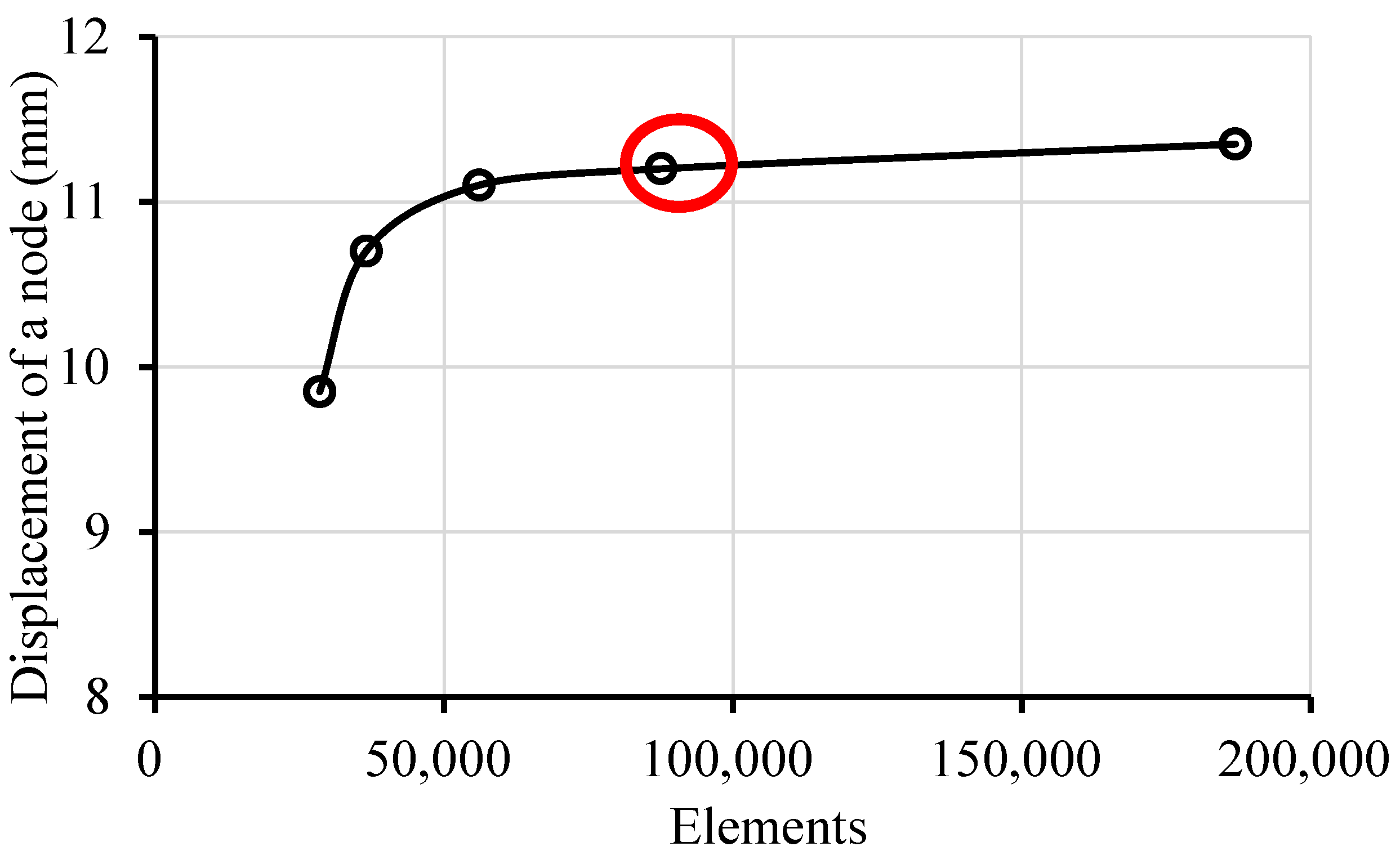
A mesh convergence investigation was performed to ensure the accuracy of the FEM simulations by implementing simple shape functions and many small elements [36,43,44]. As such, five different mesh sizes were simulated based on H-refinement, as presented in Figure 3. The result shows that the second finest mesh case with 87,550 elements has a minimum error of less than 5% compared to the third mesh case, which was considered converged. Therefore, the mesh setting for the second-finest mesh case was used for the rest of the simulations.
The weaknesses of the coreless spoiler design were identified through the first ply failure criteria and the Tsai–Hill criteria. The spars and ribs configurations with the same number of CFRP layers were proposed as an alternative to the honeycomb core. The same specifications were applied to different alternatives to maintain consistency. Thus, the effectiveness of each structure can be identified. Co-cured ribs and spars were used to avoid fastener bonding and to ensure weight saving [26]. Furthermore, several multi-rib and multi-spar configurations were also considered for the spoiler.
Once the initial structural configuration was selected from the topological optimization results, parametric optimization may then be carried out with weight reduction as the main target. For weight-saving purposes, reduction in CFRP layers and re-arrangement of lamina orientation were attempted. Again, Tsai–Hill criteria and buckling constraints had to be fulfilled.

3. Structural Design Analysis

3.1. Baseline Design

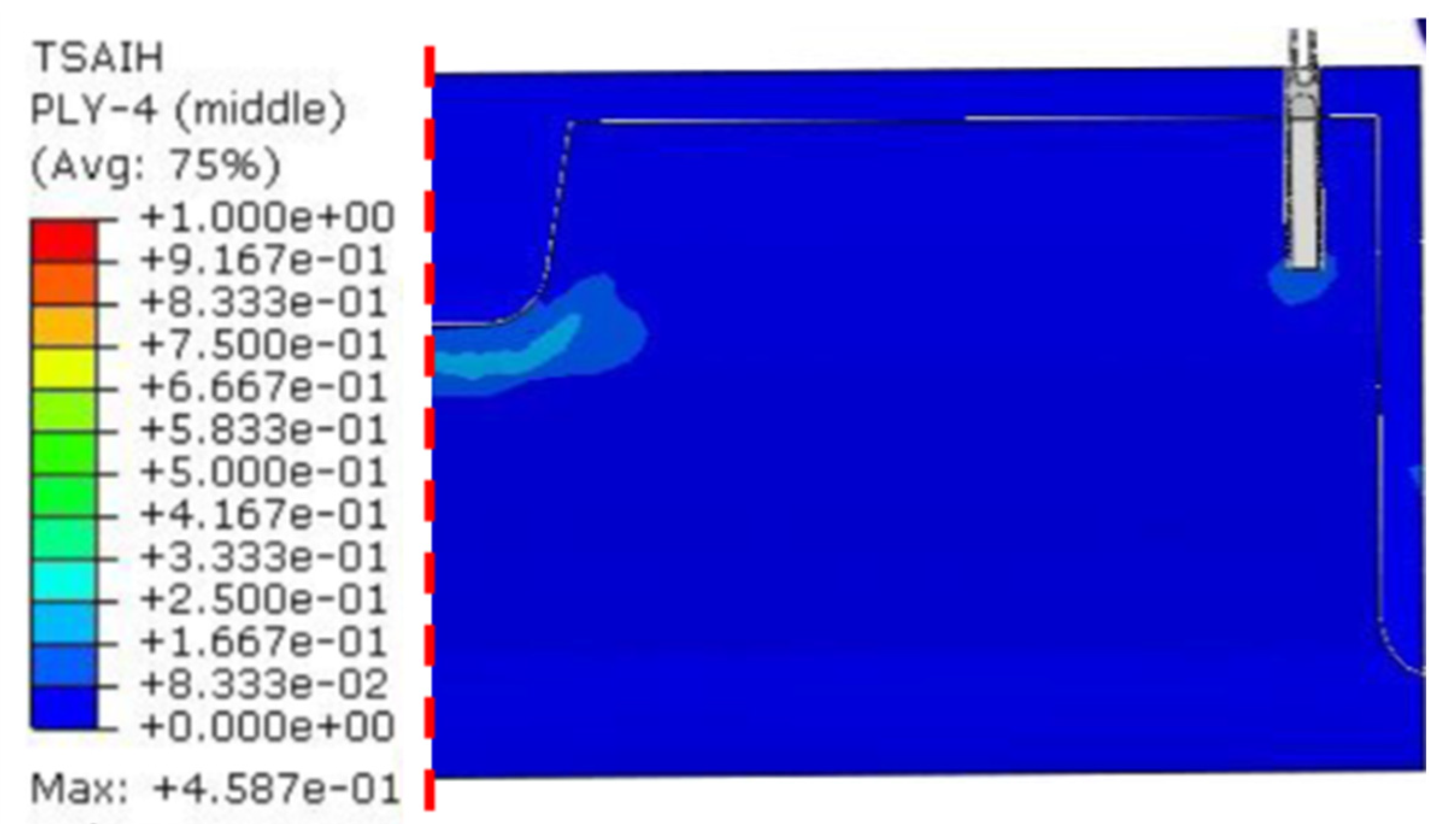
Figure 4 presents the most critical Tsai–Hill plot. Ply 4 (90° ply) of the lower skin was identified as the most critical ply with a Tsai–Hill index of 0.46. The maximum Tsai–Hill index was less than 1, indicating that this baseline design fell in a safe zone. This outcome was as expected and proved that the FE model of the spoiler was reasonable. The critical region was near the actuator due to restriction from the actuator when the spoiler was loaded. This result was expected and made the FEM result valid.

3.2. Coreless Spoiler

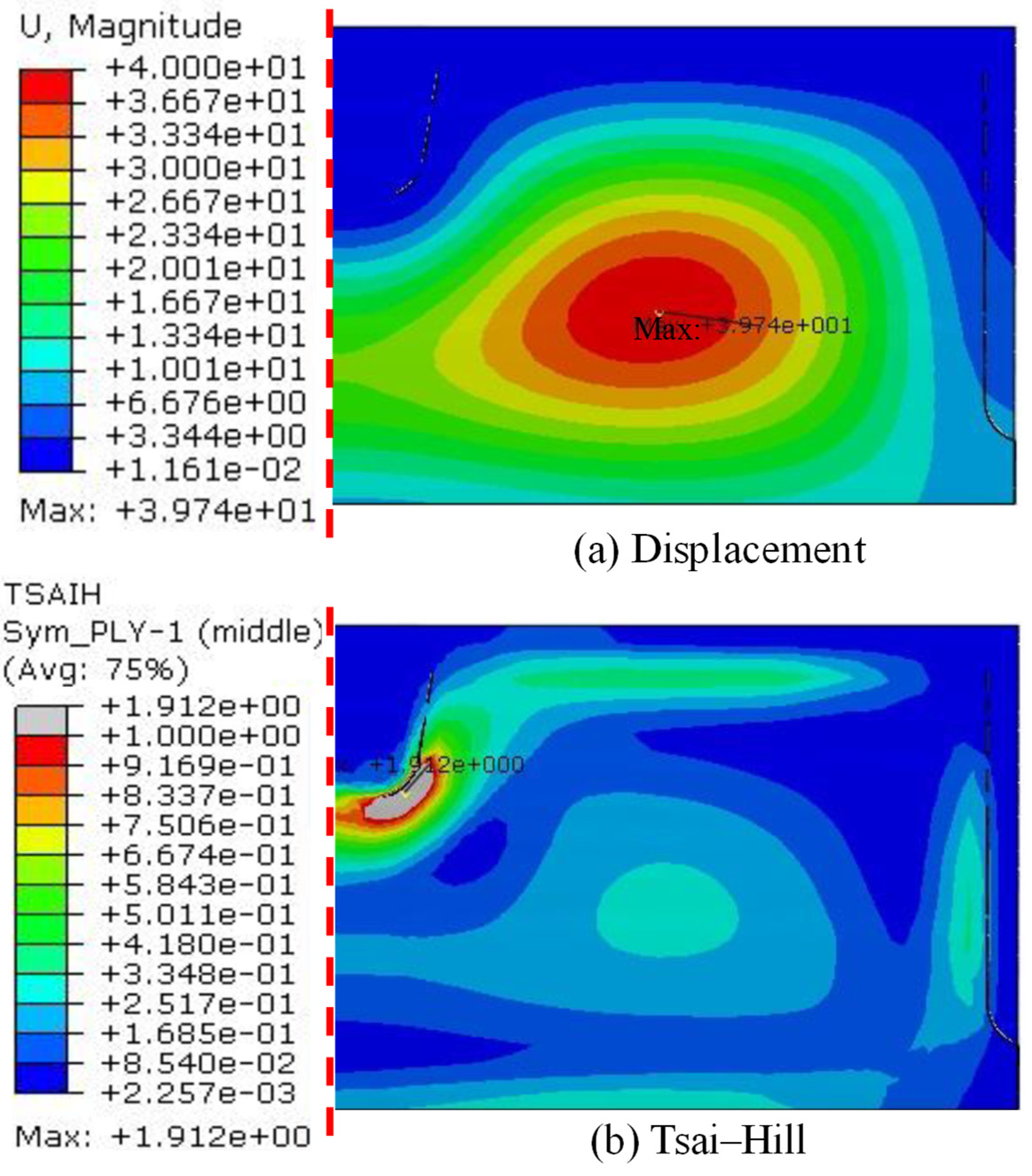
After the removal of the honeycomb core, two ribs and two spars were used for the initial design to support the spoiler skins and to maintain the original shape. The upper surface experienced the greatest displacement, around 40 mm, in the region where no support was present, as shown in Figure 5a, while the lower surface did not deflect. This was because the loading pressure was not transferred to the lower surface and the upper surface took most of the load. On the other hand, Figure 5b shows the most critical ply was the outer ply of the upper surface with a Tsai–Hill index of more than 1, around 1.9, which can be considered to indicate that this structure failed based on the first ply failure criteria. Again, the critical regions of plies were observed near the actuator due to the actuator restriction.

3.3. Topological Optimization

Figure 5b shows that the region near the coreless spoiler actuator was the most critical, requiring supports, and that to reduce deflection, a multi-composite stiffener concept, i.e., multi-spar and multi-rib, appears critical.
The multi-spar analysis started with co-cured spars placed into a coreless spoiler. Three configurations were generated with different numbers of co-cured spars, which were 13, 5, and 4. The Tsai–Hill failure index of the 13-, 5-, and 4-co-cured-spar configurations is shown in Figure 6.
The Tsai–Hill failure index for 13 co-cured spars was 0.26, and the maximum deflection was 3.9 mm. This configuration made the spoiler stiffer than the baseline. The multi-spar performances decreased by about 15–30% as the number of spars was reduced to 5 co-cured spars (0.3) and 4 co-cured spars (0.34), respectively. On the other hand, the maximum deflection for the 5 co-cured spars was 4.2 mm and 4.5 mm for the 4-co-cured-spar model. The deflection also did not vary much for the different multi-spar configurations.
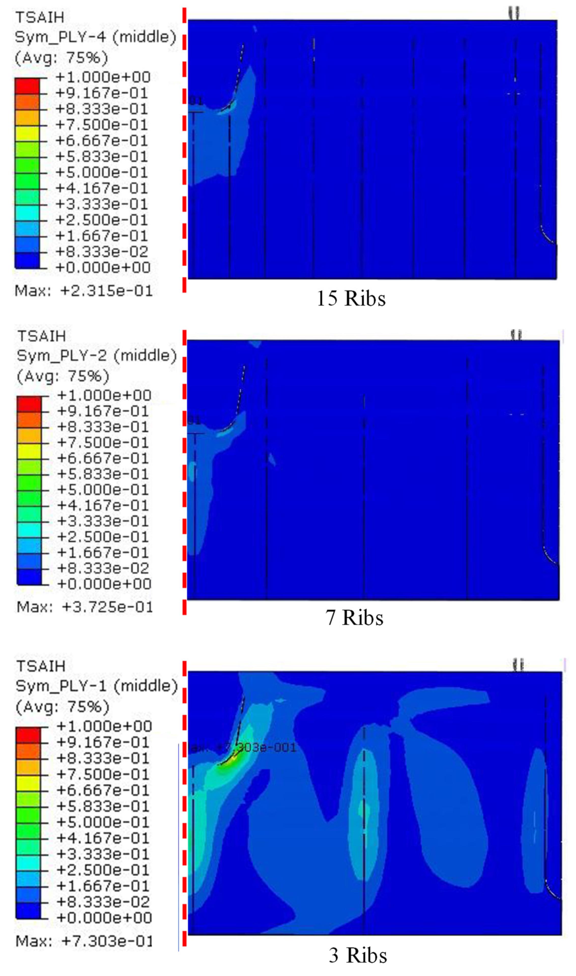
The procedure for multi-rib analysis was similar to that for multi-spar analysis. A total of three different configurations of multi-rib were also generated, with 15, 7, and 3 co-cured ribs arranged in the coreless spoiler. The results of the Tsai–Hill failure index of the multi-rib configurations are presented in Figure 7.
The Tsai–Hill index for the 15-co-cured-ribs model was 0.23, followed by 0.37 for the 7-co-cured-ribs model and 0.73 for the 3-co-cured-ribs model, respectively. The coreless spoiler performance was significantly affected by the number of ribs, with a reduction of 80% in the number of ribs, causing a 217% decrease in performance. Nevertheless, all configurations were considered safe as the Tsai–Hill index was less than 1. In terms of the maximum deflection, 5.3 mm was recorded for the 15-co-cured-rib model, 6.6 mm for the 7-co-cured-rib model, and 11 mm for the 3-co-cured-rib model. It can be observed that the deflection increased by 50% when the number of ribs was reduced by about 80%.
From the analyses of multi-spar and multi-rib models, it can be summarized that the number of spars did not affect the spoiler Tsai–Hill failure index. However, the number of ribs affected the spoiler Tsai–Hill failure index as agreed in the previous study [45]. Figure 8 presents the Tsai–Hill failure index as a function of the total mass of CFRP material for each configuration. Even though the ribs were lighter than the spars, a large number of ribs were needed to achieve a lower Tsai–Hill failure index, as shown in Figure 7.
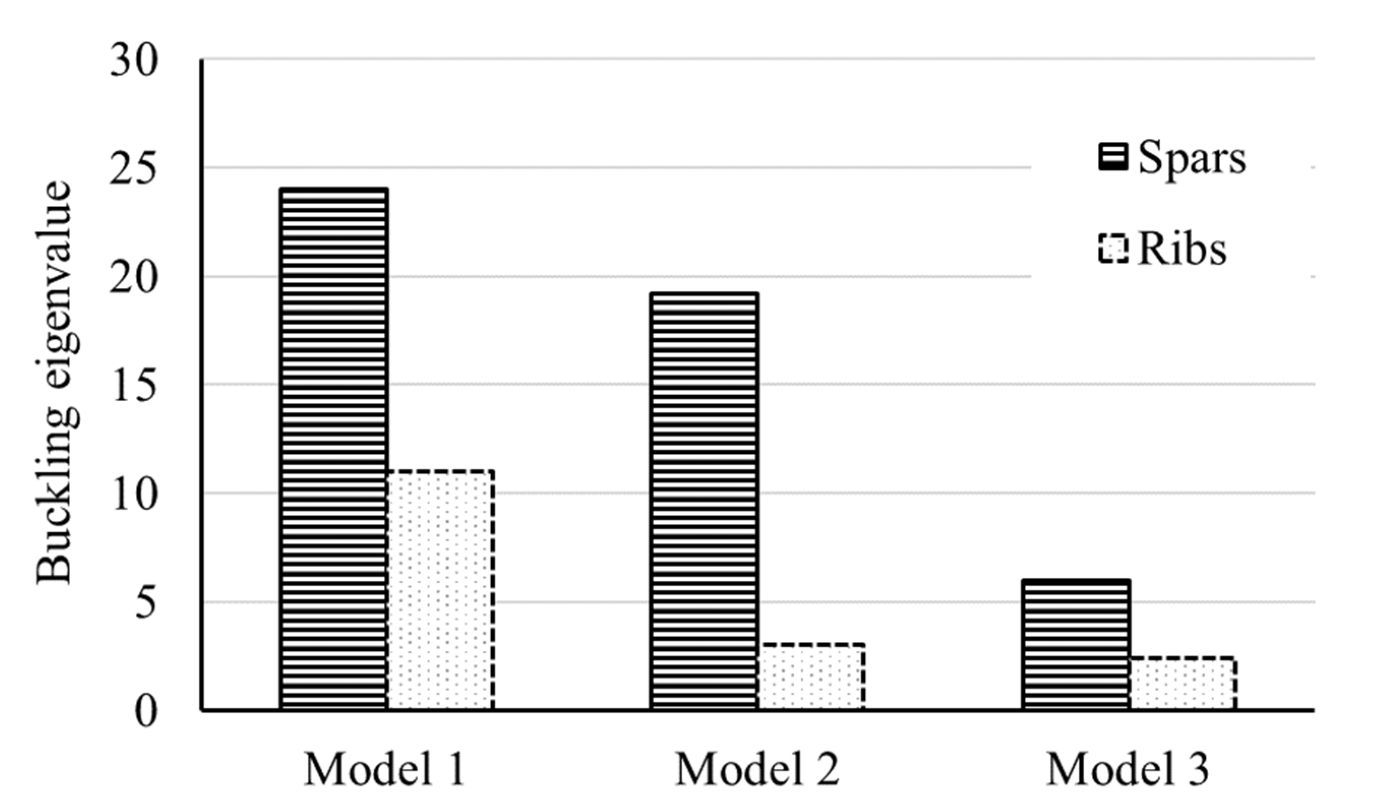
After the removal of the honeycomb core, the coreless spoiler was supported only by the thin skins of CFRP, and it tended to buckle under a bending load. Therefore, the buckling constraints were imposed on the structure to ensure the critical buckling load was well above the applied load. In Figure 9, the comparison of the buckling eigenvalue between multi-spar and multi-rib configurations was presented.
Model 1 consisted of 15-co-cured-rib cases and 13-co-cured-spar cases, while Model 2 consisted of 7-co-cured-rib cases and 5-co-cured-spar cases, and Model 3 consisted of 3-co-cured-rib cases and 4-co-cured-spar cases. It can be observed that the buckling eigenvalues for multi-spar cases were higher than multi-rib cases in all models. This indicated that the multi-spar configurations stiffened the coreless spoiler better than the multi-rib configurations. In addition, Figure 10 proves that the cases with the greatest number of ribs were unable to provide competitive buckling eigenvalue as a function of mass when compared to the multi-spar curve. It can be concluded that the multi-spar configurations surpassed the multi-rib configurations, which was also agreed upon by Ness et al. [45], who suggested that span-wise stiffening of a torsion box was more desirable in a spoiler structure.
Therefore, it was practical to improve the multi-spar configuration, although the critical buckling load for multi-rib cases was also above the applied load. Among the three multi-spar configurations, the model with 5 co-cured spars had more potential than the others as it had a sufficient high buckling eigenvalue and was not too heavy. Therefore, the 5-co-cured-spar model was sent for parametric optimization.

3.4. Analysis of Parametric Optimization

Few efforts have been made to reduce the weight of the 5-co-cured-spar model without violating the buckling constraints and Tsai–Hill failure criteria. In the first optimization, the upper and lower skins of the coreless spoiler were reduced to 18 plies with a stacking sequence of [45/-45/0/90/0/90/45/-45/90] s. The number of plies in the spar was reduced to 12 with a stacking sequence of [45/-45/45/-45/0/90] s. Figure 11 shows that the maximum Tsai–Hill index of the improved 5 co-cured spars was 0.79, indicating that the improved design did not fail. The maximum displacement was 7.4 mm, which was also less than the baseline design (12.1 mm). In addition, the buckling eigenvalue was about 4.31, which demonstrates that the buckling constraints were satisfied. The reduction in plies in the improved model has decreased the mass of the baseline design from 12.5 kg to 9.5 kg, which is about a 24% weight reduction.
The optimization process is continued with a new arrangement of the 5 co-cured spars to be designed like composite stiffeners inspired by the past studies of Purith et al. [19] and Lensus et al. [41]. This new arrangement (Figure 12) seemed likely the combination of spars and ribs that concentrated on the highest deflection region recorded by the empty coreless spoiler (Figure 5). The same number of plies and stacking sequences used in the first optimization (Figure 11) was maintained in this optimization. Figure 12 shows that the maximum deflection was 4.16 mm, which reduced up to 43% of the maximum deflection obtained in the first optimization (7.4 mm). The Tsai–Hill index (0.49) also improved by nearly 37% compared to the first optimization (0.79), as shown in Figure 13. In terms of mass, a 30% reduction (8.85 kg) was achieved compared to the baseline design, which also reduced by nearly 6% in comparison to the first optimization, as shown in Figure 13. In addition, the current optimization buckling eigenvalue was recorded at 5.5, which improved 10% of the previous optimization (4.31) and satisfied the buckling constraint. Nevertheless, this new design seems more challenging for the fabrication purpose in contrast to the first optimization, although it appears less complex in comparison with the other proposed coreless designs in [19,46] and other sandwich designs [22] for aircraft spoilers.

4. Conclusions

In this study, the weakness of spoilers without a honeycomb core was identified, and an improved design for a coreless spoiler was proposed based on topological optimization. The results proved that the co-cured spars were more effective than the co-cured ribs in supporting the coreless spoiler. Unlike the rib configurations, the number of spars had a slight effect on the Tsai–Hill index. Furthermore, the co-cured spars stiffened the structure and achieved a high critical buckling load. The results show that the five-spar configuration had the most potential to be further optimized for weight reduction in the coreless spoiler among the three different spar configurations. The mass of the spoiler can be reduced by nearly 24% from the baseline design using parametric optimization and an appropriate plies reduction and stacking sequence. It can be improved further by reducing the mass of internal structures by 6% while still fulfilling all the limitations and design criteria in FAR25.303. Both optimized designs had 18 plies with the sequence [45/-45/0/90/45/-45/90] s for upper and lower skins and 12 plies with the sequence [45/-45/45/-45/0/90] s for all ribs and spars. The second parametric optimization design appears more promising for creating a novel aircraft spoiler by replacing the honeycomb core inside the spoiler, because it reduces the maximum deflection, mass, and the Tsai–Hill index while maintaining a good buckling eigenvalue with a less complicated design. However, for real aircraft spoilers, multiple load conditions and buckling constraints must be carefully considered.

Author Contributions

Conceptualization, and Data curation H.A.I. and T.S.C.; Formal analysis, H.A.I., T.S.C., A.A.L., K.J.W., S.S.R.K., N.Y. and M.Y.Y.; Funding acquisition, S.S.R.K.; Investigation, Methodology, and Software, H.A.I. and T.S.C.; Project administration, H.A.I. and S.S.R.K.; Supervision, H.A.I.; Validation, and Visualization, H.A.I., T.S.C., A.A.L., K.J.W., S.S.R.K., N.Y. and M.Y.Y.; Writing—original draft, H.A.I. and T.S.C.; Writing—review & editing, H.A.I., T.S.C., A.A.L., K.J.W., S.S.R.K., N.Y. and M.Y.Y. All authors have read and agreed to the published version of the manuscript.

Funding

The authors acknowledge Universiti Teknologi Malaysia and the Ministry of Education for the financial support through the UTM-TDR Grant No. 05G22 and FRGS Grant No. 5F040.

Institutional Review Board Statement

Not applicable.

Informed Consent Statement

Not applicable.

Data Availability Statement

Not applicable.

Acknowledgments

The authors acknowledge Universiti Teknologi Malaysia—Aerolab for providing the research facility. The research was partially supported by Universiti Teknologi Malaysia through grant number Q.J130000.21A6.00P39, as well as the support by Universiti Putra Malaysia under Putra Grant No. GP/2018/9635100.

Conflicts of Interest

The authors declare no conflict of interest.

References

  1. DeLaurier, J. Aircraft Design Concepts: An Introductory Course; CRC Press: Boca Raton, FL, USA, 2022. [Google Scholar]
  2. Abdi, B.; Koloor, S.S.R.; Abdullah, M.R.; Amran, A.; Yahya, M.Y. Effect of Strain-Rate on Flexural Behavior of Composite Sandwich Panel. Appl. Mech. Mater. 2012, 229–231, 766–770. [Google Scholar] [CrossRef]
  3. LaPlante, G.; Marble, A.E.; MacMillan, B.; Lee-Sullivan, P.; Colpitts, B.G.; Balcom, B.J. Detection of water ingress in composite sandwich structures: A magnetic resonance approach. NDT E Int. 2005, 38, 501–507. [Google Scholar] [CrossRef]
  4. Semple, K.E.; Sam-Brew, S.; Deng, J.; Cote, F.; Yan, N.; Chen, Z.; Smith, G.D. Properties of commercial kraft paper honeycomb furniture stock panels conditioned under 65 and 95 percent relative humidity. For. Prod. J. 2015, 65, 106–122. [Google Scholar] [CrossRef]
  5. Chen, Z.; Yan, N.; Deng, J.; Semple, K.E.; Sam-Brew, S.; Smith, G.D. Influence of environmental humidity and temperature on the creep behavior of sandwich panel. Int. J. Mech. Sci. 2017, 134, 216–223. [Google Scholar] [CrossRef]
  6. Li, C.; Ueno, R.; Lefebvre, V. Investigation of an Accelerated Moisture Removal Approach of a Composite Aircraft Control Surface; Society for the Advancement of Material and Process Engineering: Oranjewoud, The Netherlands, 2006. [Google Scholar]
  7. Rahman, A. Effect of nodebond failures on structural integrity of F/A 18 trailing edge flaps. In Proceedings of the 9th Joint FAA/DoD/NASA Aging Aircraft Conference, Kansas City, MO, USA, 4–7 May 2009. [Google Scholar]
  8. Wolff, E.G.; Chen, H.; Oakes, D.J. Moisture expansion of honeycomb sandwich panels. In Proceedings of the 30th International SAMPE Technical Conference, San Antonio, TX, USA, 20–24 October 1998. [Google Scholar]
  9. Charon, A. Hot/Wet Environmental Degradation of Honeycomb Sandwich Structure Representative of F/A-18: Discolouration of Cytec FM-300 Adhesive; Defence Science and Technology Organisation Melbourne (Australia): Melbourne, Australia, 2000; Technical report (DSTOTR-0908). [Google Scholar]
  10. Hungler, P.; Bennett, L.; Lewis, W.; Brenizer, J.; Heller, A. The use of neutron imaging for the study of honeycomb structures in aircraft. Nuclear Instruments and Methods in Physics Research Section A: Accelerators, Spectrometers. Detect. Assoc. Equip. 2009, 605, 134–137. [Google Scholar] [CrossRef]
  11. Tuttle, M. Moisture diffusion in honeycomb core sandwich composites. In Proceedings of the International Conference on Composite Materials, Edinburgh, Scotland, 27–31 July 2009. [Google Scholar]
  12. Vavilov, V.; Nesteruk, D. Evaluating water content in aviation honeycomb panels by transient IR thermography. In Thermosense XXVII; SPIE: Cardiff, Wales, 2005. [Google Scholar]
  13. Ibarra-Castanedo, C.; Brault, L.; Genest, M.; Farley, V.; Maldague, X. Detection and characterization of water ingress in honeycomb structures by passive and active infrared thermography using a high resolution camera. In Proceedings of the 11th International Conference on Quantitative InfraRed Thermography, Naples, Italy, 11–14 June 2012. [Google Scholar]
  14. Swiderski, W. Nondestructive testing of honeycomb type composites by an infrared thermography method. In Proceedings of the Proc. IV Conferencia Panamericana de END, Buenos Aires, Buenos Aires, Argentina, 22–26 October 2007. [Google Scholar]
  15. Vavilov, V.P.; Klimov, A.G.; Nesteruk, D.; Shiryaev, V.V. Detecting water in aviation honeycomb structures by using transient infrared thermographic NDT. In Thermosense Xxv; SPIE: Cardiff, Wales, 2003. [Google Scholar]
  16. Doyum, A.; Duerer, M. Defect characterization of composite honeycomb panels by non-destructive inspection methods. In Proceedings of the Proceedings DGZfP Conference Weimar, Germany, 6–8 May 2002. [Google Scholar]
  17. Edwards, A.K.; Savage, S.; Hungler, P.L.; Krause, T.W. Examination of F/A-18 honeycomb composite rudders for disbond due to water using through-transmission ultrasonics. Ultragarsas/Ultrasound 2011, 66, 36–44. [Google Scholar] [CrossRef] [Green Version]
  18. Balaskó, M.; Sváb, E.; Molnár, G.; Veres, I. Classification of defects in honeycomb composite structure of helicopter rotor blades. Nuclear Instruments and Methods in Physics Research Section A: Accelerators, Spectrometers. Detect. Assoc. Equip. 2005, 542, 45–51. [Google Scholar] [CrossRef]
  19. Purith, P.; Kittikorn, C.; Pakpong, J.; Mezeix, L. Concept Design of a Single-Aisle Aircraft Spoiler by Topology Optimization. In IOP Conference Series: Materials Science and Engineering; IOP Publishing: Bristol, UK, 2020. [Google Scholar]
  20. Mei, J.; Liu, J.; Liu, J. A novel fabrication method and mechanical behavior of all-composite tetrahedral truss core sandwich panel. Compos. Part A Appl. Sci. Manuf. 2017, 102, 28–39. [Google Scholar] [CrossRef]
  21. Wei, K.; Yang, Q.; Ling, B.; Xie, H.; Qu, Z.; Fang, D. Mechanical responses of titanium 3D kagome lattice structure manufactured by selective laser melting. Extrem. Mech. Lett. 2018, 23, 41–48. [Google Scholar] [CrossRef]
  22. Liu, J.; Ou, H.; He, J.; Wen, G. Topological design of a lightweight sandwich aircraft spoiler. Materials 2019, 12, 3225. [Google Scholar] [CrossRef]
  23. Liu, J.; Chen, T.; Zhang, Y.; Wen, G.; Qing, Q.; Wang, H.; Sedaghati, R.; Xie, Y.M. On sound insulation of pyramidal lattice sandwich structure. Compos. Struct. 2019, 208, 385–394. [Google Scholar] [CrossRef] [Green Version]
  24. Liu, J.; Fan, X.; Wen, G.; Qing, Q.; Wang, H.; Zhao, G. A novel design framework for structures/materials with enhanced mechanical performance. Materials 2018, 11, 576. [Google Scholar] [CrossRef] [PubMed] [Green Version]
  25. Khan, M.S.; Abdul-Latif, A.; Koloor, S.S.R.; Petrů, M.; Tamin, M.N. Representative cell analysis for damage-based failure model of polymer hexagonal honeycomb structure under the out-of-plane loadings. Polymers 2020, 13, 52. [Google Scholar] [CrossRef]
  26. Scott, M.; Raju, J.; Cheung, A. Design and manufacture of a post-buckling co-cured composite aileron. Compos. Sci. Technol. 1998, 58, 199–210. [Google Scholar] [CrossRef]
  27. Kashyzadeh, K.; Koloor, S.R.; Bidgoli, M.O.; Petrů, M.; Asfarjani, A.A. An optimum fatigue design of polymer composite compressed natural gas tank using hybrid finite element-response surface methods. Polymers 2021, 13, 483. [Google Scholar] [CrossRef] [PubMed]
  28. McMahon, C.D.; Scott, M.L. Innovative techniques for the finite element analysis and optimisation of composites structures. In Proceedings of the 23rd International Congress of Aeronautical Sciences, Toronto, ON, Canada, 8–13 September 2002. [Google Scholar]
  29. Rispler, A.; Haviland, H.d.; Raju, J. Optimization of an Aircraft Control Surface. In Proceedings of the International ANSYS Conference, Pittsburgh, PA, USA, 20–24 April 2002. [Google Scholar]
  30. Grihon, S.; Krog, L.; Bassir, D. Numerical optimization applied to structure sizing at AIRBUS: A multi-step process. Int. J. Simul. Multidiscip. Des. Optim. 2009, 3, 432–442. [Google Scholar] [CrossRef] [Green Version]
  31. Farokhi Nejad, A.; Alipour, R.; Shokri Rad, M.; Yazid Yahya, M.; Rahimian Koloor, S.S.; Petrů, M. Using Finite Element Approach for Crashworthiness Assessment of a Polymeric Auxetic Structure Subjected to the Axial Loading. Polymers 2020, 12, 1312. [Google Scholar] [CrossRef]
  32. Joshani, M.; Koloor, S.S.R.; Abdullah, R. Damage Mechanics Model for Fracture Process of Steel-Concrete Composite Slabs. Appl. Mech. Mater. 2012, 165, 339–345. [Google Scholar] [CrossRef]
  33. Kassapoglou, C. Design and Analysis of Composite Structures: With Applications to Aerospace Structures; John Wiley & Sons: Hoboken, NJ, USA, 2013. [Google Scholar]
  34. Hansen, L.U.; Horst, P. Multilevel optimization in aircraft structural design evaluation. Comput. Struct. 2008, 86, 104–118. [Google Scholar] [CrossRef]
  35. HexWeb, Product Data: HRH-10 Aramid Fibre/Phenolic Honeycomb; H. Corporation, Editor: Dublin, Ireland, 2005; Available online: https://www.hexcel.com/ (accessed on 8 August 2022).
  36. Koloor, S.S.R.; Abdul-Latif, A.; Tamin, M.N. Mechanics of Composite Delamination under Flexural Loading. In Key Engineering Materials; Trans Tech Publications: Bäch, Switzerland, 2011; Volume 462–463, pp. 726–731. [Google Scholar]
  37. Laulusa, A.; Bauchau, O.; Choi, J.-Y.; Tan, V.; Li, L. Evaluation of some shear deformable shell elements. Int. J. Solids Struct. 2006, 43, 5033–5054. [Google Scholar] [CrossRef]
  38. Ostergaard, M.G.; Ibbotson, A.R.; Le Roux, O.; Prior, A.M. Virtual testing of aircraft structures. CEAS Aeronaut. J. 2011, 1, 83–103. [Google Scholar] [CrossRef]
  39. Schwingshackl, C.; Aglietti, G.; Cunningham, P. Determination of honeycomb material properties: Existing theories and an alternative dynamic approach. J. Aerosp. Eng. 2006, 19, 177–183. [Google Scholar] [CrossRef] [Green Version]
  40. Barton, A.B. Integrating Manufacturing Issues into Structural Optimization. Ph.D Thesis, The University of Sydney, Sydney, Australia, 2002. [Google Scholar]
  41. Koloor, S.; Ayatollahi, M.; Tamin, M. Elastic-damage deformation response of fiber-reinforced polymer composite laminates with lamina interfaces. J. Reinf. Plast. Compos. 2017, 36, 832–849. [Google Scholar] [CrossRef]
  42. Lomax, T.L. Structural Loads Analysis for Commercial Transport Aircraft: Theory and Practice; American Institute of Aeronautics and Astronautics: Reston, VA, USA, 1996. [Google Scholar]
  43. Koloor, S.S.R.; Karimzadeh, A.; Tamin, M.N.; Shukor, M.H.A. Effects of Sample and Indenter Configurations of Nanoindentation Experiment on the Mechanical Behavior and Properties of Ductile Materials. Metals 2018, 8, 421. [Google Scholar] [CrossRef] [Green Version]
  44. Alipour, R.; Alipour, R.; Fardian, F.; Koloor, S.S.R.; Petrů, M. Performance improvement of a new proposed Savonius hydrokinetic turbine: A numerical investigation. Energy Rep. 2020, 6, 3051–3066. [Google Scholar] [CrossRef]
  45. Ness, R.; Wang, J.; Kelly, D.; Reju, J.; Barton, A.; Lindsay, A. Conceptual Design of a Wing Spoiler; Tech. Rep, CRC-ACS CP 980111998; Cooperative Research Centre for Advanced Composite Structures: Melbourne, Australia, 1998. [Google Scholar]
  46. Lencus, A.; Querin, O.M.; Steven, G.P.; Xie, Y.M. Modifications to the evolutionary structural optimisation (ESO) method to support configurational optimisation. In Proceedings of the 3rd World Congress of Structural and Multidisciplinary Optimization, New York, NY, USA, 17–21 May 1999. [Google Scholar]
Figure 1. Boundary conditions of the spoiler.
Processes 10 02076 g001
Figure 2. Pressure distribution along chordwise and spanwise directions.
Processes 10 02076 g002
Figure 3. Mesh convergence of the h-refinement method.
Processes 10 02076 g003
Figure 4. Tsai–Hill of baseline spoiler (bottom view and half-model presented).
Processes 10 02076 g004
Figure 5. (a) Displacement (unit in mm) and (b) Tsai–Hill index results of coreless spoiler (top view and half-model presented).
Processes 10 02076 g005
Figure 6. The Tsai–Hill failure index for multi-spar configurations (half-model presented).
Processes 10 02076 g006
Figure 7. The Tsai–Hill failure index for multi-rib configurations (half-model presented).
Processes 10 02076 g007
Figure 8. Comparison of Tsai–Hill in terms of mass between multi-spar and multi-rib configurations.
Processes 10 02076 g008
Figure 9. Comparison of buckling eigenvalue between multi-spar and multi-rib configurations.
Processes 10 02076 g009
Figure 10. Comparison of buckling eigenvalue in terms of mass between multi-spar and multi-rib configurations.
Processes 10 02076 g010
Figure 11. Tsai–Hill of improved (first optimization) 5-co-cured-spar coreless spoiler (upper skin removed).
Processes 10 02076 g011
Figure 12. Displacement (unit in mm) of improved (second optimization) coreless spoiler (top view).
Processes 10 02076 g012
Figure 13. The mass and Tsai–Hill index comparison of the optimized designs of coreless spoiler.
Processes 10 02076 g013
Publisher’s Note: MDPI stays neutral with regard to jurisdictional claims in published maps and institutional affiliations.