Article

Hydrogen Production in Catalytic Membrane Reactors Based on Porous Ceramic Converters

A. V. Topchiev Institute of Petrochemical Synthesis, Russian Academy of Sciences, Leninsky Prosp. 29, 119991 Moscow, Russia
*
Author to whom correspondence should be addressed.
Processes 2022, 10(10), 2060; https://doi.org/10.3390/pr10102060
Submission received: 19 September 2022 / Revised: 3 October 2022 / Accepted: 5 October 2022 / Published: 12 October 2022
(This article belongs to the Special Issue Hydrogen Production and Purification)

Abstract

:
This article presents the results of the development of membrane-catalytic methods for obtaining purified hydrogen of various degrees of purity required for feeding high-, medium-, and low-temperature fuel cells. In order to conduct this, porous ceramic catalytic converters were obtained using self-propagating high-temperature synthesis. These converters are suitable for high-speed processes for producing synthesis gas with different carbon monoxide content (0.08–0.1 vol. %), which can be used to feed fuel cells of various types. Using a hybrid catalytic membrane reactor, in which the stage of catalytic conversion of organic substrates was combined with the stage of selective extraction of ultrapure hydrogen (content of H2 was not less than 99.9999 vol. %) from the reaction zone, combined carbon dioxide and steam reforming of organic substrates of various origins were carried out. The result of the work was the creation of a prototype of a small-sized electric generator plant in which a catalytic membrane reactor was combined with a solid-oxide fuel cell.

1. Introduction

One of the promising trends in the development of global energy production is the design of small-sized electric generators based on fuel cells both for powering stationary facilities and for use in the power plants of various vehicles and in portable electrical appliances [1,2,3,4].
A distinctive feature of such devices is the use of the principle of the direct conversion of the chemical energy of the fuel into electrical energy. As a result, the efficiency of fuel-cell-based power generators is almost twice as high as that of traditional power generators using internal combustion engines with electromechanical converters. Taking into account heat recovery, their efficiency can reach 70–85%. It is important to note that the amount of harmful emissions from power generators based on fuel cells is almost 100 times lower than that of traditional ones due to the absence of direct chemical contact between the fuel and the oxidizer [5,6,7,8,9,10].
There are various classifications of fuel cells, which are subdivided, most often, in terms of operating temperatures (low temperature, 60–90 °C; medium temperature, 90–200 °C; high temperature, 650–1000 °C); the type of ionic conductor electrolyte (alkaline, acid, solid polymer, molten carbonates, solid oxide ceramics, etc.); and the type of fuel used (hydrogen, synthesis gas, methanol, etc.) [11,12,13,14,15,16].
Synthesis gas (H2/CO mixture) and hydrogen are currently considered as the most important fuels for fuel cells [17,18,19,20,21,22]. These fuels can be of fossil (methane), biological (ethanol, fermentation products), synthetic (dimethyl ether), and industrial (by-products of the Fischer-Tropsch synthesis, products of the partial oxidation of aviation kerosene) origins [23,24,25,26]. At the same time, it is important to note that high-temperature fuel cells based on solid oxide ceramics (SOFC) are very undemanding in terms of the quality of raw materials and can operate on synthesis gas that does not contain sulfur compounds [27].
Medium-temperature fuel cells allow the use of technical grade hydrogen with concentrations of carbon monoxide impurities not more than 5 vol. % [28]. This circumstance makes such fuel cells especially attractive in the absence of a developed hydrogen infrastructure.
For the stable functioning of low-temperature solid polymer fuel cells (SPFCs), ultra-pure hydrogen is required (H2 content of no less than 99.9999 vol.%) with a residual CO content of less than 10 ppm [29]. This is usually obtained by the electrolysis of water; however, the most economical and widespread method at the moment is the steam reforming of methane into synthesis gas, followed by multistage purification from carbon monoxide, which is produced in modern industry by a large-scale method of pressure swing adsorption [30]. Thus, we can conclude that the stage of hydrogen extraction is an important production step which is a half of its final cost.
A possible alternative to the existing large-scale solutions is the use of small-sized catalytic membrane reactors based on porous ceramic converters aimed at producing a hydrogen-containing gas of the required composition. This can be achieved both through the number of targeted chemical processes, such as combined carbon dioxide and steam reforming of various organic substrates, selective hydrogenation of carbon oxides present in synthesis gas, and directly during its production from a wide range of hydrocarbons by using a hybrid catalytic membrane reactor where the stage of chemical transformation is combined with the stage of the selective extraction of ultrapure hydrogen from the reaction zone on a palladium-containing membrane.
The main advantages of a hybrid catalytic membrane reactor are as follows:
  • Obtaining highly pure products reduces their cost, and the possibility of placing the reactor and the separator into a single vessel significantly reduces the size of the device;
  • The possibility of bypassing the thermodynamic limitations of equilibrium processes, which makes it possible to achieve the same substrate conversions at lower temperatures or higher conversions at the same temperatures as used in a conventional flow reactor;
  • Lower process temperatures enable new reactor heating strategies. One of these approaches is the use of turbine exhaust gases, which is an energy efficient technological solution. In addition, this approach reduces the cost of structural materials, which reduces the cost and increases the safety of the processes.
Thus, combining processes based on the principle of simultaneous chemical transformation and the separation of reaction products is a powerful tool for increasing their productivity. For this reason, catalytic membrane reactors represent a promising practical application for fuel cell power generators [31,32,33].
This paper presents the results of reforming and selective hydrogenation of carbon monoxide and continuous membrane hydrogen extraction from the reactor for the processes of carbon dioxide, steam, and combined carbon dioxide and steam reforming of organic substrates using a porous ceramic catalytic converter.

2. Experimental Part

2.1. Investigation Objects

The study was carried out using porous ceramic catalytic converters, which were produced using the SHS and sol-gel method according to previously described procedures [34,35].
These converters are hollow ceramic cylinders with porous gas-permeable walls, which have a mounting cap for installation in a steel reactor by means of a clamping nut on one side and a tight plug that prevents gas from slipping past the walls on the other. Thus, the principle of operation of the converter is based on the forced diffusion of the reactant from the outer wall to the inner wall through an extended system of tortuous channels modified with nanosized catalytic components. Figure 1 shows the appearance and main parameters of such a converter.
The main parameters of the converter were: total length, ~115 mm; length of the operation area (distance from the mounting cap to the plug), ~97 mm; tube outer diameter, ~25 mm; wall thickness, ~7 mm; operating volume, ~0.04 dm3; diameter of open pores, 1–3 µm; porosity, more than 50%.
The composition of the converters used in the study was varied (Table 1).

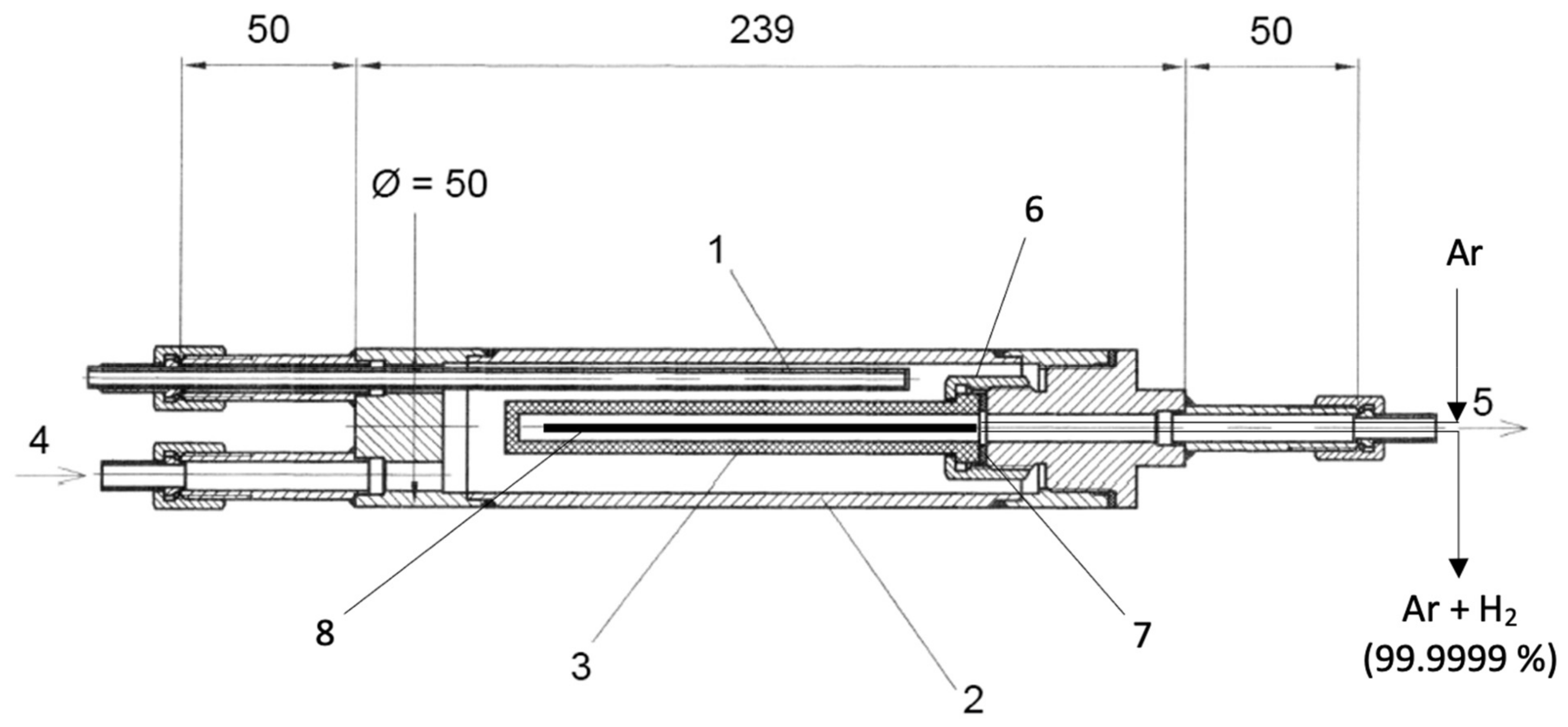
2.2. Design of a Laboratory Setup and a Catalytic Membrane Reactor

The catalytic transformations of carbon oxides and organic substrates of fossil (methane), biological (ethanol, fermentation products), synthetic (dimethyl ether), and industrial (by-products of the Fischer-Tropsch synthesis, products of partial oxidation of aviation kerosene) origin were studied using an original laboratory setup and a catalytic membrane reactor designed as shown in Figure 2 and Figure 3.

2.3. Experimental Procedure

Before the experiment on the laboratory bench described above, preparatory operations were carried out. Particularly, the catalytic converter was mounted in the membrane reactor (item 17 in Figure 2), the reactor was assembled, sealed, and mounted in the installation position specified by the flow chart, and the whole system was pressurized with argon for 15 min. In order to prevent undesirable oxidation of the catalytically active components of the converter with air oxygen, the reactor with the installed sample was heated to the initial temperature of the process in an argon flow (99.998% GOST 10157-79) fed from gas cylinder (1) through reducer (6). The argon flow rate was set at 2.5 L/h and was controlled using an RRG Eltochpribor BUIP-1 electronic regulator (9). As the required temperature was reached, the argon supply was stopped and a separate feed supply was started (depending on the process, pre-prepared model liquid and gas mixtures or single substrates were used as the feed) from gas cylinder (2) and built-in containers (4) and (5) and High-Pressure Pump 5001 liquid dispensers (11). The volumetric feed flow rates of the substrates were set according to requirements of the experiment, which were specified in each specific research section. The reactant flows were mixed in the mixing valve (13).
In experiments with the extraction of ultrapure hydrogen from the reaction zone, argon carrier gas was supplied from cylinder (3) to the palladium-containing membrane mounted in the reactor. The argon flow was set at 30 mL/min by means of a fine adjustment valve (8). In order to homogenize the total liquid flow sent to the reactor, it was preliminarily evaporated in a coil evaporator (14) at a temperature of 200 °C. The heating of the evaporator was controlled using an OVEN TRM-210 temperature controller (15). Next, the gas vapor reaction mixture was fed to the catalytic membrane reactor (17). Heating and temperature maintenance of the reactor furnace were controlled with an OWEN TRM251 temperature processor (TP-0198 Thermocouple, chromel-alumel (K)) (15). The pressure in the reactor was controlled using an OVEN IP65 pressure sensor and an OVEN 2TRM0 pressure indicator (16). The product gas flow rate into the receiver was measured using a Sinagawa DC2CM gas clock (21).
The obtained gas sample was analyzed by gas chromatography to determine the contents of inorganic (H2, CO, CO2) and hydrocarbon (C1-C5) gases on CrystalLux-4000M chromatographs (22) equipped with FID and TCD detectors. After analysis, the gas flow was routed to SOFC (26) to generate electricity. The operating parameters of the fuel cell were controlled by measuring instruments (27). The liquid sample was concentrated in the liquid separator (18), and then by opening the shut-off valve (19) it was poured into the liquid receiver (20). Next, the sample volume was measured, the aqueous phase was separated from the organic layer, and the organic phase was analyzed by gas chromatography/mass spectrometry (qualitatively) (23) and gas liquid chromatography (quantitatively) (24). The data obtained from analytical instruments were processed using the computer workstation (25) software. At the end of the experiment, the catalytic reactor was cooled down to room temperature in an argon atmosphere in order to prevent unwanted oxidation of the catalyst.
The contents of hydrogen, carbon oxides, and methane in the reaction products were determined by gas chromatography on a CrystalLux-4000M chromatograph (Meta-Chrom, Russia) with a thermal conductivity detector using high-purity argon (99.998% GOST 10157-79) at a flow rate of 10 mL/min as the carrier gas and a 1 m × 3 mm adsorption column packed with the SKT-activated carbon (0.2–0.3 mm particle size). The column, detector, and evaporator temperatures were 120 °C. The gas concentrations were found from calibration curves using dedicated NetChrom v2.1 software.
Concentrations of carbon monoxide below 5 vol. % were determined more accurately using a calibrated Riken Keiki Model RI-550A IR spectrometer.
The C1–C5 hydrocarbon gases were identified on a CrystalLux-4000M chromatograph (Meta-Chrom, Russia) using a flame ionization detector (FID) and helium (TU 0271-001-45905715-02) as the carrier gas. The following gas flow rates were established: helium, 30 mL/min.; hydrogen, 35 mL/min.; air, 300 mL/min. An HP-PLOT/Al2O3 chromatographic column (Agilent Technologies, USA), 50 m × 0.32 mm, film thickness of 8.0 µm, was used for analysis. The column temperature was 120 °C, the detector temperature was 230 °C, and the evaporator temperature was 250 °C.
Liquid organic reaction products were identified by GC/MS and GLC. GC/MS analysis was carried out using a Thermo Focus DSQ II gas chromatograph/mass spectrometer with a quadrupole mass analyzer and an electron energy of 70 eV. The voltage of the electron multiplier was 1244 V. The ion source temperature was 280 °C. The interface temperature was 280 °C. Detection was carried out in the selected ion monitoring (SIM) mode.
The content of liquid organic products was determined by GLC on a Varian 3600 chromatograph (Varian Chromatography System, USA), FID, Chromtek SE-30 capillary column, 25 m × 0.25 mm, Df = 0.33 μm. The temperature regime was as follows: 50 °C (5 min.), 10 °C/min., 280 °C, Tinj = 250 °C, Pinj = 1 bar, and a flow division ratio of 1/200, with helium (TU 0271-001-45905715-02) as the carrier gas.

2.4. Calculations

The conversion of substrates, %, was calculated as follows:
X i = n i , 0 n i n i , 0 · 100 %
where ni,0, ni are the numbers of moles of i-th component at the reactor inlet and outlet, respectively.
The mole fraction of a compound in the reaction products was calculated as follows:
n i = C i · ω o u t · t 100 % · V M
where Ci is the concentration of the i-th product in the mixture, vol. %; ω o u t is the volumetric flow rate of the mixture at the outlet of the reactor, L/h (STP); t is the time of experiment, h; and V M is the gas molar volume at STP (22.4 L/mol).
The specific volumetric productivity of the catalytic converter for the target product, L/(h·dm3conv.) was calculated as follows:
ρ = C i · ω o u t 100 · V c o n v .
where Vconv. is the operating volume of the catalytic converter, dm3.
The volumetric feed rate to the reactor, h−1, was calculated as follows:
Q = ω o u t V p o r .
The contact time of a compound in the reactor, s, was calculated as follows:
τ = V p o r . · T 1 · P 2 ω i n · T 2 · P 1 · 3600
Here, Vpor. is the total pore volume of the converter, dm3:
V p o r . = ε · V c o n v .
where ε is the converter porosity, %; ω i n is the volumetric flow rate of the mixture at the reactor inlet, L/h (STP); T1 (P1) is the temperature (pressure) at STP, respectively; and T2 (P2) is the temperature (pressure) in the reactor, respectively, K (atm).
The extraction rate of ultrapure hydrogen, %, was calculated as follows:
E H 2 = C H 2   m e m b . · ω o u t     m e m b . C H 2 · ω o u t + C H 2   m e m b . · ω o u t     m e m b .
where C H 2   m e m b . is the hydrogen concentration in the output stream of the palladium-containing membrane, %; ω o u t   m e m b . is the total flow of hydrogen and argon at the outlet of the palladium-containing membrane, L/h; and C H 2 is the hydrogen concentration at the reactor outlet, %.

3. Results and Discussion

3.1. Water–Gas Shift Reaction on Porous Catalytic Converters

The highest CO conversion was achieved via water–gas shift reaction using porous catalytic converters:
C O + H 2 O C O 2 + H 2
As a result of studies on water–gas shift reactions in specially synthesized porous catalytic converters of various compositions, the temperature dynamics of this process was established. When the volumetric flow rate of a vapor gas mixture to the reactor was approximately 7000 h−1, the CO conversion over the most active copper/iron and nickel/cobalt systems at 600–650 °C reached 86% (Figure 4). An important finding was that a further increase in temperature induced a noticeable decrease in the conversion of carbon monoxide due to exothermicity of this reversible reaction (41 kJ/mol). At lower temperatures, the reaction equilibrium was shifted towards the products, mainly due to the presence of a twofold molar excess of water in the reaction medium.
Noteworthy is the relatively high activity of the iron copper system, especially at temperatures below 500 °C, and, on the contrary, the low activity of the corundum converter containing deposited palladium cobalt components over the entire temperature range studied.
When the Ni-Co and FeNi36 (invar) converters were used, methane was formed as a by-product in an amount not exceeding 1 vol. %. No methane formation was observed with the other two catalysts (Table 2).
As expected, an increase in the volumetric feed flow rate also led to an increase in the specific productivity of the converters to hydrogen. From Figure 5, it follows that the converters based on Ni-Co and Cu-Fe systems provided the highest productivity, which made it possible to achieve 18,800 and 15,900 L/(h·dm3) of hydrogen, respectively.

3.2. Steam Reforming of Carbon Monoxide Mixed with Hydrogen

It is known that the carbon dioxide and steam reforming of methane and ethanol produces synthesis gas, which is a mixture of carbon monoxide and hydrogen in ratio of 1 to 3 mol/mol, depending on the type of process. To reduce the costs associated with the component separation of the resulting synthesis gas, it would be highly appropriate to carry out steam reforming of carbon monoxide directly in a mixture with its own hydrogen. For this purpose, we chose the two most active converters among those tested in this reaction, namely the Ni-Co and Cu-Fe converters. However, it is worth noting here that the presence of hydrogen in the initial mixture had an adverse effect on the equilibrium constant of the main reaction, which led to a decrease in the carbon monoxide conversion. Therefore, to increase the conversion, a four-fold molar excess of water with respect to CO was used.
From the data presented in Table 3, it follows that the nickel cobalt catalytic system had a noticeable advantage over the copper chromium one, making it possible to obtain more hydrogen-rich mixtures containing not more than 800 ppm of carbon monoxide, with other conditions being the same.

3.3. Production of Ultrapure Hydrogen Using the Hybrid Catalytic Membrane Reactor

Ultrapure hydrogen (H2 content of no less than 99.9999 vol.%) has wide range of practical applications. It is needed, for example, in the organic synthesis of highly pure substances, both for large-tonnage purposes and for fine chemical synthesis. In addition, it is required for low-temperature fuel cells, the electrochemical platinum-containing components of which are particularly sensitive to carbon monoxide poisoning. For this purpose, a process of combined carbon dioxide and steam reforming of various hydrocarbons in a so-called hybrid catalytic membrane reactor was developed. In this process, a porous catalytic converter, which runs the chemical reaction, was combined with a hydrogen-selective membrane based on a palladium alloy. Furthermore, the scope of the process included a wide range of liquid and gaseous organic substrates of fossil (methane), biological (ethanol, fermentation products), and synthetic (dimethyl ether) origin.
One more benefit of the hybrid catalytic membrane reactor is that it is a fairly compact device applicable not only in stationary or mobile but also in portable power generators for portable electronics.

3.4. Carbon dioxide Reforming of Methane

As shown in Figure 6, the implementation of the process of the carbon dioxide reforming of methane, in which ultrapure hydrogen was recovered from the reaction zone on a palladium-containing membrane, significantly intensified the conversion of methane compared to the traditional flow process carried out under the same conditions (catalytic converter: Ni(Al)-Co; Ptot. = 2 atm; Q = 600 h−1), which was obviously associated with a shift in the chemical equilibrium towards the products due to the selective removal of one product, in accordance with the Le Chatelier–Brown principle.
C H 4 + C O 2 2 C O + 2 H 2
It is also evident from Figure 6 that the selective extraction of hydrogen and the directly related intensification of the carbon dioxide reforming of methane began at temperatures of about 400 °C, while the greatest difference between methane conversions in the membrane and traditional flow reactors was attained at 600 °C. This was apparently attributable to the maximum rate of hydrogen diffusion through the wall of the palladium-containing membrane at this temperature.
In addition, it is known that an increase in the partial pressure of hydrogen increases the degree of its extraction through palladium-containing membranes. However, an increase in the total pressure in the system reduces the rates of reactions that are accompanied by increase in the volume, which also applies to the reforming.
While attempting to find a trade-off point between these two oppositely directed effects, in order to identify the optimal conditions for the carbon dioxide reforming of methane, we found that at 700 °C, an increase in the total pressure in the membrane reactor from 2 to 5 atm did not induce a noticeable decrease in methane conversion, while the degree of hydrogen extraction increased from 63 to 83 %. Meanwhile, in the traditional flow process, which was carried out without hydrogen extraction, an increase in the total pressure in the system deteriorated the efficiency of the process by decreasing the methane conversion by 19% (Figure 7).

3.5. Carbon Dioxide Reforming of Ethanol

In view of the good prospects of the trend towards the use of renewable raw materials, ethanol can also refer to this type of raw material for hydrogen production:
C 2 H 5 O H + C O 2 3 C O + 3 H 2
The implementation of carbon dioxide reforming of ethanol in the membrane reactor suppressed the side reaction of methane formation. This effect became more pronounced with increasing the temperature of the process, i.e., when more hydrogen was removed from the reaction zone (Figure 8).

3.6. Steam Reforming of Methane

In the steam reforming of methane in the membrane reactor, such as in carbon dioxide reforming, the conversion of methane became higher than that in the traditional flow mode following a temperature rise. However, the numerical difference was not that pronounced. This was probably due to the greater adsorption capacity of water molecules compared to carbon dioxide molecules on the surface of the palladium-containing membrane, which greatly hindered the selective extraction of hydrogen from the reaction zone (Figure 9).
For example, at a temperature of 700 °C, a total pressure of 2 atm, the conversion of methane in the steam reforming process reached 69%, while the degree of hydrogen extraction was only 36%, while in carbon dioxide reforming of methane carried out under the same conditions, the degree of hydrogen extraction was almost twice as high (63%) at a similar substrate conversion. In the steam reforming of methane, this result could be attained by increasing the total pressure to 5 atm, but the conversion simultaneously decreased by 6%, i.e., down to 63%. It was shown experimentally that the difference between methane conversions in the membrane and traditional flow regimes in the pressure range studied (2–5 atm) did not exceed 10%.
In view of the foregoing, an increase in the H2O/CH4 molar ratio adversely affected the hydrogen permeation through the palladium-containing membrane, but significantly intensified the whole process of methane steam reforming, with the methane conversion increasing by 16%, from 69 to 85% (Figure 10). At the same time, the total hydrogen productivity increased by 35%.

3.7. Steam Reforming of Ethanol and Fermentation Products

The ethanol steam reforming process carried out in the membrane reactor also demonstrated a significant intensification of the chemical reaction compared to the traditional flow process, due to the removal of hydrogen from the reaction zone. This was specifically indicated by a significant increase in the total hydrogen flow at the reactor outlet (Figure 11).
The steam reforming of a model mixture simulating the products of enzymatic fermentation of corn, carried out in a Ni(Al)-Co catalytic converter, led to complete gasification already at 350 °C. However, for the above-indicated reasons, the natural 25-fold molar excess of water over the dissolved hydrocarbon substrates (mainly alcohols) hampered the extraction of ultrapure hydrogen on the palladium-containing membrane. Therefore, in this case, the total increase in hydrogen productivity was 18 % relative to that in the traditional flow process, and the degree of extraction of ultrapure hydrogen did not exceed 32%.

3.8. Steam Reforming of Dimethyl Ether

It was found that the use of a membrane catalytic reactor significantly increased the yield of hydrogen in the steam reforming of dimethyl ether (DME), which is a synthetic raw material source. DME conversion can proceed according to three pathways depending on the molar excess of water:
C H 3 O C H 3 + 2 H 2 O 2 C O + 5 H 2
C H 3 O C H 3 + H 2 O 2 C O + 4 H 2
C H 3 O C H 3 + 3 H 2 O 2 C O 2 + 6 H 2
It was found that in the membrane process, the hydrogen flow at the reactor outlet was approximately 30 % higher (W(H2) = 0.8 mol/h at 700 °C and Q(DME) = 0.25 mol/h) than in the traditional flow process. The separated ultrapure hydrogen amounted to 50% of the total hydrogen amount produced (Figure 12).
In turn, an increase in the water to dimethyl ether molar ratio led, as expected, to an increase in the hydrogen yield, an increase in the carbon dioxide concentration, and a decrease in the residual content of methane in the product gas (Figure 13).

3.9. Combined Carbon Dioxide and Steam Reforming of the Fischer–Tropsch Synthesis By-Products

The reforming of by-products of the Fischer–Tropsch synthesis in porous catalytic converters enables the efficient conversion of the organic pollutants present in wastewater and industrial off-gases into synthesis gas, which is known to be a valuable intermediate for petrochemistry and a promising energy carrier. This adds economic benefits to a plant’s operation due to the useful utilization of industrial waste and significantly increases its environmental friendliness.
The experimental results of testing of nickel/cobalt converters under conditions optimized for the specified task are presented below.
The by-products of the Fischer–Tropsch synthesis included methane, carbon dioxide, and water with dissolved oxygenated compounds (Table 4). The molar ratios between the reaction components were CH4/CO2/H2O = 1/10/2.5 [36,37,38,39].
As a result of the carbon dioxide and steam reforming of the off-products of the Fischer–Tropsch synthesis, the conversion of methane and water-soluble organic compounds reached almost 100%. The reactor effluents included synthesis gas and water purified from dissolved organic components with the characteristics given in Table 5, Table 6 and Table 7.

3.10. Carbon Dioxide and Steam Reforming of Aviation Kerosene Partial Oxidation Products

This method of producing synthesis gas is very promising for powering perspective aircraft power generators based on catalytic membrane reactors combined with solid-oxide fuel cells.
As can be seen from the data in Table 8, high-temperature steam and the carbon dioxide reforming of a model mixture simulating the products of partial oxidation of aviation kerosene resulted in an almost complete conversion of C1–C4 hydrocarbons to synthesis gas in all versions of the tested catalytic converters. The highest conversion of methane (about 90%) was achieved in the Pd/Ni-Al sample.

3.11. Hydrogenation of Carbon Oxides Present in the Products of Ethanol Steam Reforming in a Porous Catalytic Converter

The development of a method for obtaining purified hydrogen for modern fuel-cell-based power generators via the hydrogenation of carbon oxides in porous catalytic converters may become an effective small-scale alternative to the existing large-scale industrial processes with pressure swing adsorption units and high-pressure hydrogen storage systems. This would enable the design of explosion-proof small-sized and mobile power plants for both stationary facilities and transport vehicles. It is important to note that the development of kinetically controlled catalytic hydrogenation of carbon monoxide could also become an effective way to obtain synthesis gas of a specified composition.
During the steam reforming process, ethanol is converted into synthesis gas and a number of by-products formed via parallel reactions:
C 2 H 5 O H + 3 H 2 O 2 C O 2 + 6 H 2
C 2 H 5 O H C O + C + 3 H 2
C 2 H 5 O H C H 4 + C O + H 2
C 2 H 5 O H C 2 H 4 + H 2 O
Table 9 presents the compositions of model mixtures that reflect the compositions of the products formed in these reactions.
Studying the catalytic hydrogenation of carbon monoxide and carbon dioxide contained in model mixture No. 1, which was identical in composition to the gaseous products of ethanol steam reforming (Table 9) in a porous nickel/aluminum/cobalt converter showed that, even at a temperature of 325 °C, the conversion of these substrates reached 88.8 and 60.2%, respectively (Figure 14). Thus, the residual CO content in the refined gas did not exceed 0.5%.
In the hydrogenation of model mixture No. 2, previously purified from carbon dioxide (Table 9), at the same temperature, we demonstrated the possibility of attaining a higher conversion of CO (>97%), which decreased the CO concentration in the product gas to a level acceptable for feeding medium-temperature fuel elements (<0.1%).
The data depicted in Figure 14 suggest that the increased intensity of carbon monoxide hydrogenation in model mixture No. 2 may be due to the absence of diffusion inhibition caused by the competitive adsorption of CO and CO2 molecules in the catalyst active sites, which was the case for model mixture No. 1.
The study of the kinetics of carbon monoxide hydrogenation (model mixture No. 2) showed that in the temperature range of 200–250 °C, the carbon monoxide hydrogenation reaction obeyed the zero-order equation (Figure 15).
The similar values of the apparent activation energies found for the solid and granulated converter (Ea ~ 57 kJ/mol) and reported previously [32,33] indicated that the mechanism of the hydrogenation reaction remained invariable for the two process designs. However, the pre-exponential factor, which reflects the reaction rates, was approximately three times higher (k0 = 5.4·105 mol/(L·s)) for the solid converter than for the granulated one (k0 = 1.7·105 mol/(L·s)). The increase in the reaction rate was, most likely, due to the forced diffusion of substrate molecules in the limited space of the open pores of the converter, which ensured a greater number of particle collisions with active catalytic components formed on the inner surface (Figure 16).
The results of kinetic studies showed that, in addition to the high conversion of CO and the release of purified hydrogen, the carbon monoxide hydrogenation process provided the formation of synthesis gas of a specified composition for production of a wide range of hydrocarbons [40,41].

3.12. Implementation of a Catalytic Membrane Reactor in Combination with a Solid Oxide Fuel Cell in Small-Sized Power Generators

One of the ways of enabling the practical application of membrane reactors based on porous catalytic converters can be their joint use with various types of fuel cells in small-sized power generators. To demonstrate this possibility, we designed a prototype of such a setup equipped with a solid-oxide fuel cell (SOFC) with a solid ceramic electrolyte consisting of zirconium oxide stabilized by yttrium oxide. The appearance of this SOFC is shown in Figure 17 and the main characteristics are summarized in Table 10.
The main advantages of SOFCs compared to other fuel cells are their high power and unpretentiousness with regards to the composition of the fuel gas, i.e., resistance to the poisoning of the electrochemical parts of the device with catalytic poisons, in particular carbon monoxide. In our case, the SOFC was fed by the synthesis gas obtained by the reforming of hydrocarbon raw materials of fossil (methane), biological (ethanol, corn fermentation products (Table 11)), and synthetic (dimethyl ether) origins as well as industrial waste (aviation kerosene partial oxidation products).
Below are the input and output parameters of the process of steam reforming of some organic substrates used to generate fuel gas to feed the SOFC (Table 12).

4. Conclusions

It was shown experimentally that the hydrogenation of hydrocarbon reforming gases to methane in porous catalytic nickel/aluminum/cobalt converters provided the efficient removal of carbon oxide impurities, which made these gases suitable for feeding not only high- but also medium-temperature fuel cells, which are very sensitive to CO content in concentrations exceeding 3–5 vol. %.
It was established that the reaction rates were three times higher for the solid converter than for the granulated converter, which was a consequence of the forced diffusion of substrate molecules in the limited space of the open catalytic channels of the converter. This fundamental conclusion is based on the structural organization of the converter, which had up to 107 channels with an effective cross-section of 3 μm per cm2 of the surface, whereas a much less dense packing of active particles in the bulk catalyst layer led to a noticeably lower productivity of the traditional flow reactor.
It was shown that the steam reforming of carbon monoxide in the porous catalytic nickel/cobalt converters was a highly efficient alternative method for the production of hydrogen-containing mixtures (up to 18,800 L/(h·dm3) productivity) with ultralow concentrations of carbon monoxide (below 800 ppm). In addition, such hydrogen-rich mixtures are more calorific than the original mixtures and can be used as fuels with enhanced useful output in high- and medium-temperature fuel cells, as well as reagents in various chemical processes that require high-purity hydrogen.
An original hybrid catalytic membrane reactor was developed combining the chemical conversion of reactants in a porous catalytic converter with the selective extraction of ultrapure hydrogen (the proportion of H2 being not less than 99.9999 vol.%) from the reaction zone on a palladium–ruthenium membrane. As is known, ultrapure hydrogen is needed to feed low-temperature fuel cells, which are particularly sensitive to carbon monoxide poisoning at concentrations above 10 ppm.
The wide scope of the practical applications of this reactor for the production of ultrapure hydrogen in the processes of carbon dioxide and steam reforming of liquid and gaseous organic substrates of fossil (methane), biological (ethanol, fermentation products), and synthetic (dimethyl ether) origins were demonstrated.
It was shown that in the hybrid catalytic membrane reactor, the main process parameters noticeably increased compared to those in the traditional flow process due to the shift in chemical equilibrium. For example, in the carbon dioxide reforming of methane, the conversion increased by 30%, while the degree of extraction of ultrapure hydrogen reached 83%. Thus, a high performance, along with a low weight and size, could allow the efficient use of the hybrid catalytic membrane reactor in portable power generation devices.
The processing of the Fischer–Tropsch synthesis by-products demonstrated that the porous catalytic converters could be successfully used, among other things, for the high purification of liquid and gaseous industrial wastes from various kinds of organic pollutants by converting them into synthesis gas, an important intermediate product and energy carrier, which, after the separation of carbon dioxide, can be used as a reagent in petrochemistry to obtain valuable products or in solid-oxide fuel cells and to generate electricity.
The utilization of a gas turbine engine exhaust in membrane reactors based on porous catalytic converters combined with a solid-oxide fuel cell may become an additional source of power in auxiliary power units for the power supply of onboard aircraft systems.
The results of the studies of the prototype of an electricity-generating device demonstrated the possibility of creating the most advanced power plants based on a catalytic membrane reactor combined with a solid-oxide fuel cell, which has great potential for practical applications for the safe power supply of stationary facilities and various types of transport vehicles.

Author Contributions

Investigation, A.S.F.; Conceptualization, M.V.T.; Supervision, A.B.Y. All authors have read and agreed to the published version of the manuscript.

Funding

The work was carried out within the framework of the state task of the Topchiev Institute of Petrochemical Synthesis of the Russian Academy of Sciences (Topic No. 5).

Acknowledgments

The authors are grateful to Uvarov V.I. (ISMAN) for preparing samples of porous ceramic converters, Zaikov Yu.P. and the research team of the IHTE Ural Branch of the Russian Academy of Sciences headed by him for providing, mounting, and adjustment of the solid-oxide fuel cell for testing.

Conflicts of Interest

The authors declare no conflict of interest.

Abbreviations

DME—dimethyl ether; SHS—self-propagating high-temperature synthesis; SOFC—solid oxide fuel cells; SPFC—solid polymer fuel cells.

References

  1. Ajanovic, A.; Haas, R. Prospects and impediments for hydrogen and fuel cell vehicles in the transport sector. Int. J. Hydrog. Energy 2020, 46, 10049–10058. [Google Scholar] [CrossRef]
  2. Kovač, A.; Paranos, M.; Marciuš, D. Hydrogen in energy transition: A review. Int. J. Hydrog. Energy 2021, 46, 10016–10035. [Google Scholar] [CrossRef]
  3. Ogden, J.M. Prospects for Hydrogen in the Future Energy System; Research Report—UCD-ITS-RR-18-07; Institute of Transportation Studies, University of California: Davis, CA, USA, 2018; Available online: https://escholarship.org/uc/item/52s28641#main (accessed on 18 September 2022).
  4. Filippov, S.P.; Yaroslavtsev, A.B. Hydrogen energy: Development prospects and materials. Russ. Chem. Rev. 2021, 90, 627–643. [Google Scholar] [CrossRef]
  5. Chakraborty, S.; Dash, S.K.; Elavarasan, R.M.; Kaur, A.; Elangovan, D.; Meraj, S.T.; Kasinathan, P.; Said, Z. Hydrogen Energy as Future of Sustainable Mobility. Front. Energy Res. 2022, 10, 893475. [Google Scholar] [CrossRef]
  6. Garland, N.L.; Papageorgopoulos, D.C.; Stanford, J.M. Hydrogen and Fuel Cell Technology: Progress, Challenges, and Future Directions. Energy Procedia 2012, 28, 2–11. [Google Scholar] [CrossRef] [Green Version]
  7. Fan, L.; Tu, Z.; Chan, S.H. Recent development of hydrogen and fuel cell technologies: A review. Energy Rep. 2021, 7, 8421–8446. [Google Scholar] [CrossRef]
  8. Yue, M.; Lambert, H.; Pahon, E.; Roche, R.; Jemei, S.; Hissel, D. Hydrogen energy systems: A critical review of technologies, applications, trends and challenges. Renew. Sustain. Energy Rev. 2021, 146, 111180. [Google Scholar] [CrossRef]
  9. Staffell, I.; Scamman, D.; Velazquez Abad, A.; Balcombe, P.; Dodds, P.E.; Ekins, P.; Shah, N.; Ward, K.R. The role of hydrogen and fuel cells in the global energy system. Energy Environ. Sci. 2019, 12, 463–491. [Google Scholar] [CrossRef] [Green Version]
  10. Staffell, I.; Dodds, P.; Scamman, D.; Abad, A.V.; Dowell, N.M.; Ward, K.; Agnolucci, P.; Papageorgiou, L.; Shah, N.; Ekins, P. The Role of Hydrogen and Fuel Cells in Future Energy Systems. H2FC Supergen. 2017. Available online: https://www.h2fcsupergen.com/wp-content/uploads/2015/08/J5212_H2FC_Supergen_Energy_Systems_WEB.pdf (accessed on 18 September 2022).
  11. Sundén, B. Chapter 8—Fuel Cell Types—Overview. In Hydrogen, Batteries and Fuel Cells; Academic Press: Cambridge, MA, USA, 2019; pp. 123–144. ISBN 9780128169506. [Google Scholar] [CrossRef]
  12. Revankar, S.; Majumdar, P. Fuel Cells e Principles, Design and Analysis; CRC Press: New York, NY, USA, 2014; p. 750. Available online: https://www.routledge.com/Fuel-Cells-Principles-Design-and-Analysis/Revankar-Majumdar/p/book/9781420089684 (accessed on 18 September 2022).
  13. Singhal, S.C.; Kendall, K. High Temperature Solid Oxide Fuel Cells-Fundamentals, Design and Applications; Elsevier: Oxford, UK, 2004; p. 406. ISBN 9780080508085. Available online: https://cds.cern.ch/record/640123/files/1856173879_TOC.pdf (accessed on 18 September 2022).
  14. Hacker, V.; Mitsushima, S. Fuel Cells and Hydrogen; Elsevier: Amsterdam, The Netherlands, 2018; p. 296. ISBN 9780128115374. [Google Scholar]
  15. Brandon, N. Solid Oxide Fuel Cells e Lifetime and Reliability; Elsevier: 2017. Available online: https://www.elsevier.com/books/fuel-cells-and-hydrogen/hacker/978-0-12-811459-9 (accessed on 18 September 2022).
  16. Albarbar, A.; Alrweq, M. Proton Exchange Membrane Fuel Cell-Design, Modelling and Performance Assessment Techniques; Springer: Berlin/Heidelberg, Germany, 2018; ISBN 978-3-319-70727-3. [Google Scholar] [CrossRef]
  17. Habibollahzade, A.; Rosen, M.A. Syngas-fueled solid oxide fuel cell functionality improvement through appropriate feedstock selection and multi-criteria optimization using Air/O2-enriched-air gasification agents. Appl. Energy 2021, 286, 116497. [Google Scholar] [CrossRef]
  18. Jia, J.; Li, Q.; Luo, M.; Wei, L.; Abudula, A. Effects of gas recycle on performance of solid oxide fuel cell power systems. Energy 2011, 36, 1068–1075. [Google Scholar] [CrossRef]
  19. Gadsbøll, R.; Thomsen, J.; Bang-Møller, C.; Ahrenfeldt, J.; Henriksen, U.B. Solid oxide fuel cells powered by biomass gasification for high efficiency power generation. Energy 2017, 131, 198–206. [Google Scholar] [CrossRef] [Green Version]
  20. D’Andrea, G.; Gandiglio, M.; Lanzini, A.; Santarelli, M. Dynamic model with experimental validation of a biogas-fed SOFC plant. Energy Convers. Manag. 2017, 135, 21–34. [Google Scholar] [CrossRef]
  21. Subotić, V.; Baldinelli, A.; Barelli, L.; Scharler, R.; Pongratz, G.; Hochenauer, C.; Anca-Couce, A. Applicability of the SOFC technology for coupling with biomass-gasifier systems: Short- and long-term experimental study on SOFC performance and degradation behaviour. Appl. Energy 2019, 256, 113904. [Google Scholar] [CrossRef]
  22. Langnickel, H.; Rautanen, M.; Gandiglio, M.; Santarelli, M.; Hakala, T.; Acri, M.; Kiviaho, J. Efficiency analysis of 50 kWe SOFC systems fueled with biogas from waste water. J. Power Sources Adv. 2020, 2, 100009. [Google Scholar] [CrossRef]
  23. Bicer, Y.; Khalid, F. Life cycle environmental impact comparison of solid oxide fuel cells fueled by natural gas, hydrogen, ammonia and methanol for combined heat and power generation. Int. J. Hydrog. Energy 2018, 45, 3670–3685. [Google Scholar] [CrossRef]
  24. Boretti, A. Production of hydrogen for export from wind and solar energy, natural gas, and coal in Australia. Int. J. Hydrog. Energy 2020, 45, 3899–3904. [Google Scholar] [CrossRef]
  25. Cao, L.; Yu, I.K.; Xiong, X.; Tsang, D.C.; Zhang, S.; Clark, J.H.; Hu, C.; Ng, Y.H.; Shang, J.; Ok, Y.S. Biorenewable hydrogen production through biomass gasification: A review and future prospects. Environ. Res. 2020, 186, 109547. [Google Scholar] [CrossRef]
  26. Cormos, C.-C. Hydrogen and power co-generation based on coal and biomass/solid wastes co-gasification with carbon capture and storage. Int. J. Hydrog. Energy 2012, 37, 5637–5648. [Google Scholar] [CrossRef]
  27. Stambouli, A.; Traversa, E. Solid oxide fuel cells (SOFCs): A review of an environmentally clean and efficient source of energy. Renew. Sustain. Energy Rev. 2002, 6, 433–455. [Google Scholar] [CrossRef]
  28. Larminie, J.; Dicks, A. Medium and High Temperature Fuel Cells. In Fuel Cell Systems Explained; John Wiley & Sons, Ltd: Chichester, UK, 2003; ISBN 9781118878330. [Google Scholar]
  29. Sazali, N.; Wan Salleh, W.N.; Jamaludin, A.S.; Mhd Razali, M.N. New Perspectives on Fuel Cell Technology: A Brief Review. Membranes 2020, 10, 99. [Google Scholar] [CrossRef]
  30. Ishaq, H.; Dincer, I.; Crawford, C. A review on hydrogen production and utilization: Challenges and opportunities. Int. J. Hydrog. Energy 2021, 47, 26238–26264. [Google Scholar] [CrossRef]
  31. Barbieri, G.; Violante, V.; Di Maio, F.P.; Criscuoli, A.; Drioli, E. Methane Steam Reforming Analysis in a Palladium-Based Catalytic Membrane Reactor. Ind. Eng. Chem. Res. 1997, 36, 3369–3374. [Google Scholar] [CrossRef]
  32. Tong, J.; Matsumura, Y. Pure hydrogen production by methane steam reforming with hydrogen-permeable membrane reactor. Catal. Today 2006, 111, 147–152. Available online: https://link.springer.com/article/10.1007/s11244-008-9129-5 (accessed on 18 September 2022). [CrossRef]
  33. Algieri, C.; Coppola, G.; Mukherjee, D.; Shammas, M.; Calabro, V.; Curcio, S.; Chakraborty, S. Catalytic Membrane Reactors: The Industrial Applications Perspective. Catalysts 2021, 11, 691. [Google Scholar] [CrossRef]
  34. Uvarov, V.I.; Kapustin, R.D.; Fedotov, A.S.; Kirillov, A.O. Synthesis of Porous Ceramic Materials for Catalytically Active Membranes by Technological Combustion and Sintering. Glas. Ceram. 2020, 77, 221–225. [Google Scholar] [CrossRef]
  35. Fedotov, A.S.; Uvarov, V.I.; Tsodikov, M.V.; Moiseev, I.I.; Paul, S.; Heyte, S.; Simon, P.; Marinova, M.; Dumeignil, F. Synthesis of 1,3-Butadiene from 1-Butanol on a Porous Ceramic [Fe,Cr]/γ-Al2O3(K,Ce)/α-Al2O3 Catalytic Converter. Kinet. Catal. 2020, 61, 390–404. [Google Scholar] [CrossRef]
  36. Eliseev, O.L. Gas-to-liquid technologies. Russ. J. Gen. Chem. 2009, 79, 2509–2519. [Google Scholar] [CrossRef]
  37. Zoppi, G.; Pipitone, G.; Gruber, H.; Weber, G.; Reichhold, A.; Pirone, R.; Bensaid, S. Aqueous phase reforming of pilot-scale Fischer-Tropsch water effluent for sustainable hydrogen production. Catal. Today 2020, 367, 239–247. [Google Scholar] [CrossRef]
  38. Zoppi, G.; Pipitone, G.; Pirone, R.; Bensaid, S. Aqueous phase reforming process for the valorization of wastewater streams: Application to different industrial scenarios. Catal. Today 2021, 387, 224–236. [Google Scholar] [CrossRef]
  39. D’Angelo, M.F.N.; Ordomsky, V.; Schouten, J.C.; Van Der Schaaf, J.; Nijhuis, T.A. Carbon-Coated Ceramic Membrane Reactor for the Production of Hydrogen by Aqueous-Phase Reforming of Sorbitol. ChemSusChem 2014, 7, 2007–2015. [Google Scholar] [CrossRef]
  40. Jiaying, Z. Kinetic study of carbon monoxide methanation over mesoporous Ni-Mo catalyst prepared by a hydrothermal method. Prog. React. Kinet. Mech. 2019, 44, 3–17. [Google Scholar] [CrossRef]
  41. Mutschler, R.; Moioli, E.; Luo, W.; Gallandat, N.; Züttel, A. CO2 hydrogenation reaction over pristine Fe, Co, Ni, Cu and Al2O3 supported Ru: Comparison and determination of the activation energies. J. Catal. 2018, 366, 139–149. [Google Scholar] [CrossRef]
  42. Stabnikov, V.N. Distillation and Rectification of Ethyl Alcohol, 2nd ed.; Food Industry Publishing House: Moscow, Russia, 1969; p. 224. [Google Scholar]
Figure 1. Appearance of a porous ceramic catalytic converter.
Processes 10 02060 g001
Figure 2. Design of the laboratory setup for the dehydrogenation of ethylbenzene to styrene. Designations: (1) argon gas cylinder for purging the reactor; (2) raw gas mixture cylinder; (3) gas cylinder with argon carrier gas for purging the hydrogen-selective membrane; (4) container with liquid substrate; (5) container with distilled water; (6) gas reducer; (7) three-way valve; (8) fine adjustment valve for the argon carrier gas flow rate; (9) gas flow regulator valve; (10) gas flow controller; (11) liquid pump; (12) liquid pump flow controller; (13) mixing valve for gas–liquid flows; (14) evaporator; (15) temperature processor; (16) pressure sensor; (17) electrically heated catalytic membrane reactor; (18) liquid separator; (19) shut-off valve; (20) liquid receiver; (21) gas flow indicator; (22) gas chromatograph; (23) gas chromatograph/mass spectrometer; (24) gas liquid chromatograph; (25) computing workstation for data processing; (26) SOFC; (27) SOFC instrumentation and controls.
Processes 10 02060 g002
Figure 3. Design of catalytic membrane reactor (the dimensions are in mm). Designations: (1) thermocouple pockets; (2) reactor vessel; (3) porous catalytic converter; (4) feed supply; (5) outlet for total reaction products; (6) clamping nut; (7) graphite gasket; (8) hydrogen-selective membrane made of palladium alloy (in the hybrid version of the reactor).
Processes 10 02060 g003
Figure 4. Temperature dependence of carbon monoxide conversion in water–gas shift reaction in porous catalytic converters of variable composition.
Processes 10 02060 g004
Figure 5. Dependence of the specific productivity to hydrogen on the conditional contact time for water–gas shift reaction in porous catalytic converters of variable composition.
Processes 10 02060 g005
Figure 6. Comparison of the temperature dependences of carbon dioxide reforming of methane accompanied by ultrapure hydrogen extraction from the reaction zone (membrane process) and without extraction (traditional process).
Processes 10 02060 g006
Figure 7. Dependences of methane conversion upon carbon dioxide reforming and degree of extraction of ultrapure hydrogen on the total pressure in the system in the membrane and traditional processes.
Processes 10 02060 g007
Figure 8. Comparison of the temperature dependences of methane concentrations in the reaction products of the carbon dioxide reforming of ethanol carried out in the membrane and traditional processes.
Processes 10 02060 g008
Figure 9. Comparison of temperature dependences of methane steam reforming accompanied by ultrapure hydrogen extraction from the reaction zone (membrane process) and without extraction (traditional process).
Processes 10 02060 g009
Figure 10. Dependence of methane steam reforming and the degree of extraction of ultrapure hydrogen on the H2O/CH4 molar ratio (T = 700 °C).
Processes 10 02060 g010
Figure 11. Comparison of the temperature dependences of ethanol steam reforming accompanied by ultrapure hydrogen extraction from the reaction zone (membrane process) and without extraction (traditional process).
Processes 10 02060 g011
Figure 12. Comparison of temperature dependences of methane concentrations in the products of steam reforming of dimethyl ether in membrane and traditional processes.
Processes 10 02060 g012
Figure 13. Molar excess of hydrogen over carbon monoxide formed in the process of steam reforming of dimethyl ether carried out at different reactant ratios.
Processes 10 02060 g013
Figure 14. Temperature dependence of the conversion of carbon oxides in the process of hydrogenation of model mixtures identical in composition to the gaseous products of ethanol steam reforming.
Processes 10 02060 g014
Figure 15. Dependence of the concentration of carbon monoxide on the conditional contact time for the process of hydrogenation of model mixture No. 2.
Processes 10 02060 g015
Figure 16. Arrhenius plots for hydrogenation of carbon monoxide contained in model mixture No. 2.
Processes 10 02060 g016
Figure 17. Appearance and internal structure of a solid-oxide fuel cell.
Processes 10 02060 g017
Table 1. Composition and method of preparation of catalytic converters synthesized for the study.
NoComponentsComponent Contents, wt. %Preparation Method
1Ni(Al)-Co45(5)–50SHS
2Ni-Co50–50SHS
3Cu-Fe50–50SHS
4FeNi36 (invar)64–36SHS
5Pd-Co/α-Al2O30.034–0.017/α-Al2O3SHS + sol-gel
6Pd/Ni-Al0.07/α-Al2O3SHS + sol-gel
7Pd-Co/Ni-Al0.034–0.017/Ni-AlSHS + sol-gel
8Mn/Ni-Al0.07/α-Al2O3SHS + sol-gel
Table 2. Component concentrations in the products of water–gas shift reaction in porous catalytic converters of variable composition (T = 650 °C).
ConverterComponent Concentrations in the Reaction Products, vol. %
H2COCH4CO2
Cu-Fe70.611.30.018.1
Ni-Co47.07.20.245.7
FeNi36 (invar)45.411.41.042.2
Pd-Co/α-Al2O322.855.80.021.4
Table 3. Initial data and outlet characteristics of the steam reforming of carbon monoxide mixed with hydrogen.
ConverterProcess ParametersConcentration of Components, vol. %
T, °CV, h−1X(CO), %Initial MixtureReaction Products
H2COH2COCH4CO2
Ni-Co450700088.581.518.583.061.951.5613.43
Ni-Co500700091.193.56.592.840.643.513.01
350096.591.560.315.532.60
Cu-Fe500700055.094.722.401.371.53
350068.894.701.652.271.38
Ni-Co550700092.498.21.897.510.191.480.82
350096.097.770.081.950.20
Table 4. Composition of Fischer–Tropsch synthesis products dissolved in water, rel. %.
AlcoholsKetonesAcids
MethanolEthanolButanolPentanolAcetoneButanoneAcetic Acid
2.818.21.30.41.34.05.0
Table 5. Output parameters of the carbon dioxide and steam reforming of the off-products of the Fischer–Tropsch synthesis (Ni-Co, 780 °C).
Q, h−1XCH4, %Ρsyngas, l/(h∙dm3)H2/CO, mol/mol
16,0009970000.8
32,0009613,0000.9
64,0008523,0001.1
Table 6. Composition of the product gas (Ni-Co, 780 °C).
Q, h−1Concentration, vol. %
H2COCH4CO2
16,00017.822.70.159.4
32,00018.621.10.356.0
64,00019.018.01.062.0
Table 7. Composition of the product liquids (Ni-Co, 780 °C).
Q, h−1Concentration, %
AlcoholsKetonesAcids
MethanolEthanolButanolPentanolAcetoneButanoneAcetic Acid
16,00000.00100000
32,0000.0010.00100000
64,0000.0010.00200000
Table 8. Input and output parameters of the carbon dioxide and steam reforming of the products of partial oxidation of aviation kerosene (T = 800 °C, Q = 25,000 h−1; H2O/(comb. comp.) = 2 mol/mol; C(CO2) = 9.41 vol. %, C(N2) = 76.40 vol. %.).
Residual Combustible Components of the MixtureC0,
vol. %
Pd/Ni-AlPd-Co/Ni-AlMn/Ni-Al
C,
vol. %
X,
%
C,
vol. %
X,
%
C,
vol. %
X,
%
H2038.85-35.85-36.23-
CO6.638.194.996.3720.426.4621.26
CH42.120.2989.600.7670.500.6576.00
C2H44.16010001000100
C3H60.72010001000100
C4H100.56010001000100
Table 9. Component composition of model mixtures simulating gaseous products of ethanol steam reforming.
Model Mixture No.Concentration, vol. %
H2COCH4CO2
159.01.817.421.8
278.62.618.8-
Table 10. Characteristics of SOFC.
Current Density300 mA/cm2
Power density150 mW/cm2
Specific volume3.3 L/kW
Specific weight1.6 kg/kW
Table 11. Component composition of the products of enzymatic fermentation of corn [42].
ComponentConcentration, vol. %
ethanol80
propanol5
n-butanol5
n-pentanol10
Table 12. Input and output parameters of the process of steam reforming of various organic substrates in a catalytic fuel gas generator for SOFC.
SubstrateH2O/sub.,
vol./vol.
Q, h−1T, °CReaction Products, vol. %
H2COCH4CO2
methane2700080073.013.01.014.0
ethanol1,510,00072.013.70.613.7
fermentation products715,00073.83.60.622.0
Publisher’s Note: MDPI stays neutral with regard to jurisdictional claims in published maps and institutional affiliations.

