Article

The Failure Law and Control Technology of Large-Section Roadways in Gently Inclined Soft Coal Seams

1
State Key Laboratory of Coal Resources and Safe Mining, School of Mines, China University of Mining and Technology, Xuzhou 221116, China
2
Shanxi Lu’an Group Zuoquan Wulihou Coal Industry Co., Ltd., Jinzhong 030600, China
3
Shandong Province Key Laboratory of Mine Mechanical Engineering, Shandong University of Science and Technology, Qingdao 266590, China
*
Author to whom correspondence should be addressed.
Processes 2022, 10(10), 1993; https://doi.org/10.3390/pr10101993
Submission received: 31 July 2022 / Revised: 25 September 2022 / Accepted: 28 September 2022 / Published: 2 October 2022

Abstract

:
The proportion of the coal and rock masses in different areas of surrounding rocks is quite different when a large-section coal roadway is excavated in gently inclined soft coal seams. Different creep failure occurs in coal and rock masses under high stress, which results in uneven deformations of roadways and difficulties in maintenance. This work studied the belt grooves of the 2103 working face in the lower coal group of the Wulihou Coal Mine. Theoretical analysis and measured geomechanical evaluation were used to analyze the failure causes of the surrounding rocks of the roadway. The failure law of large-section roadways in the gently inclined soft coal seams was studied using finite-difference numerical simulation software. Combined with the results of mathematical analysis, surrounding rocks were divided into regions. Surrounding-rock control schemes for different areas, such as grouting reinforcement, strengthening support, and pressure-relief grooving, were proposed separately and verified by numerical simulations. Strengthening the supports could reduce the deformations of area I, and pressure-relief grooving could control the deformations of area IV. The roadway and support system formed an anchored composite supporting body after grouting reinforcement, which greatly improved the bearing capacity and controlled the deformations of surrounding rocks. The fine on-site application effect and the improved non-symmetrical deformation verified the theoretical analysis, numerical simulations, and control technologies. The results provide a scientific basis and useful reference for similar projects.

1. Introduction

China ranks first in coal reserves and second in recoverable reserves in the world. The buried depth of the coal seam, affected by the occurrence state, is relatively large, and more than 90% of coal resources are mined by underground mining [1,2]. According to incomplete statistics, tens of thousands of kilometers of new roadways are excavated in China every year, and mine roadways are necessary passages for staff, mining equipment and materials, and mine ventilation. However, different special geological structures exist in the coal-measure strata, and special geological structures significantly affect the stability of surrounding rocks of roadways. Inclined and gently inclined coal seams have an extensive influence on roadways. Therefore, the surrounding-rock stability of roadways of inclined coal seams is vital for the safe and efficient mining of heading stope [3,4,5,6].
Scholars have studied the control technology of the surrounding rocks of roadways in inclined coal seams and focus on large inclination angles and steeply inclined and inclined coal seams; the section is mostly less than 5 m. Wang et al. [7,8,9] studied the supporting technology of roadways in coal seams with large inclination angles. Stress distribution and deformation and failure show obvious asymmetric characteristics. The middle part of the roadway roof, high side, and included angle between the floor and the high side are vital for controlling deformations, and their supports are reinforced. Kulakov et al. [10,11,12,13] studied the control technology of the asymmetric deformation of surrounding rocks of steeply inclined roadways. The roadway has the largest shoulder angle and bending moment on the low side, which is prone to coal swelling; the high side of the roadway has maximum axial force with an internal expansion. Moreover, new support measures are proposed for the asymmetric failure of the roadway.
Wu et al. [14,15,16] adopted the “three-height” anchoring and prestressed anchor-cable truss technology based on the uneven and asymmetric failure of roadways in inclined rock formations in the Huainan Xieqiao Mine, China. The structurally strengthened internal and external load-bearing structure formed by the coupling support technology is used to control the uneven and asymmetric deformation of roadways, with a good control effect. Wang [17,18,19,20] aimed at the non-uniform instability mechanism of roadways in inclined coal seams. The control principle of high strength and high prestress is used to develop the coupled support technology of high preload force, strong anchor bolts and cables, strong protective-surface components, and strong side support. The asymmetric coupling support pattern of grouting anchor cables and bolts and lengthened bolts is implemented for special key areas. The support and surrounding rocks can satisfy the coupling of strength, stiffness, and structures for the long-term stability of roadways.
There are some studies on the roadway-supporting technology in inclined coal seams rather than on the failure and deformation mechanism of the surrounding rocks of large-section roadways in gently inclined soft coal seams. Therefore, it is of great theoretical and practical value to study the failure law of the surrounding rocks of roadways in inclined coal seams and formulate corresponding technical measures for the safe and economical mining of coal resources.
This work studied the belt grooves of the 2103 working face in the lower coal group of the Wulihou Coal Mine. Theoretical analysis, numerical simulations, on-site industrial tests, and monitoring were used to study the failure and deformation law of the surrounding rocks of large-section roadways of gently inclined soft coal seams and formulate corresponding technical measures.

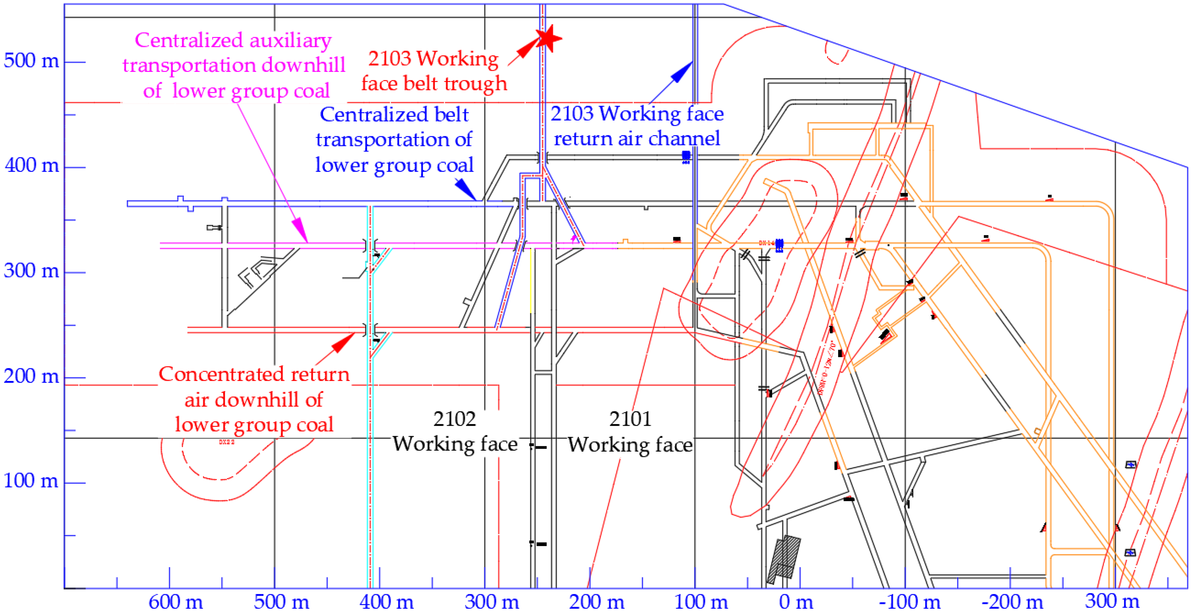
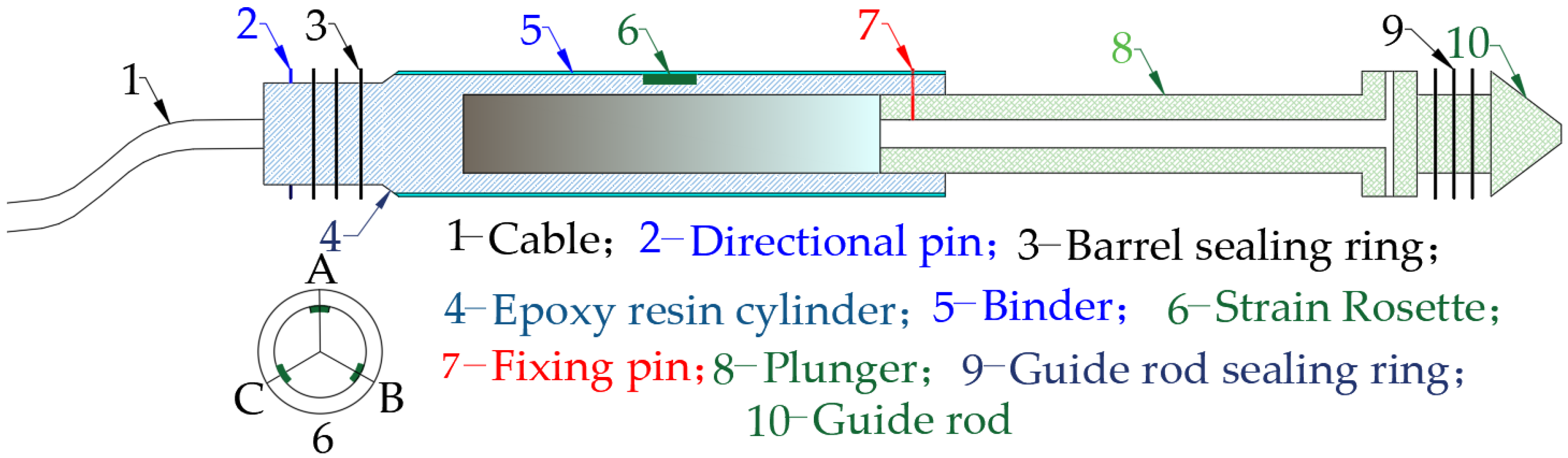
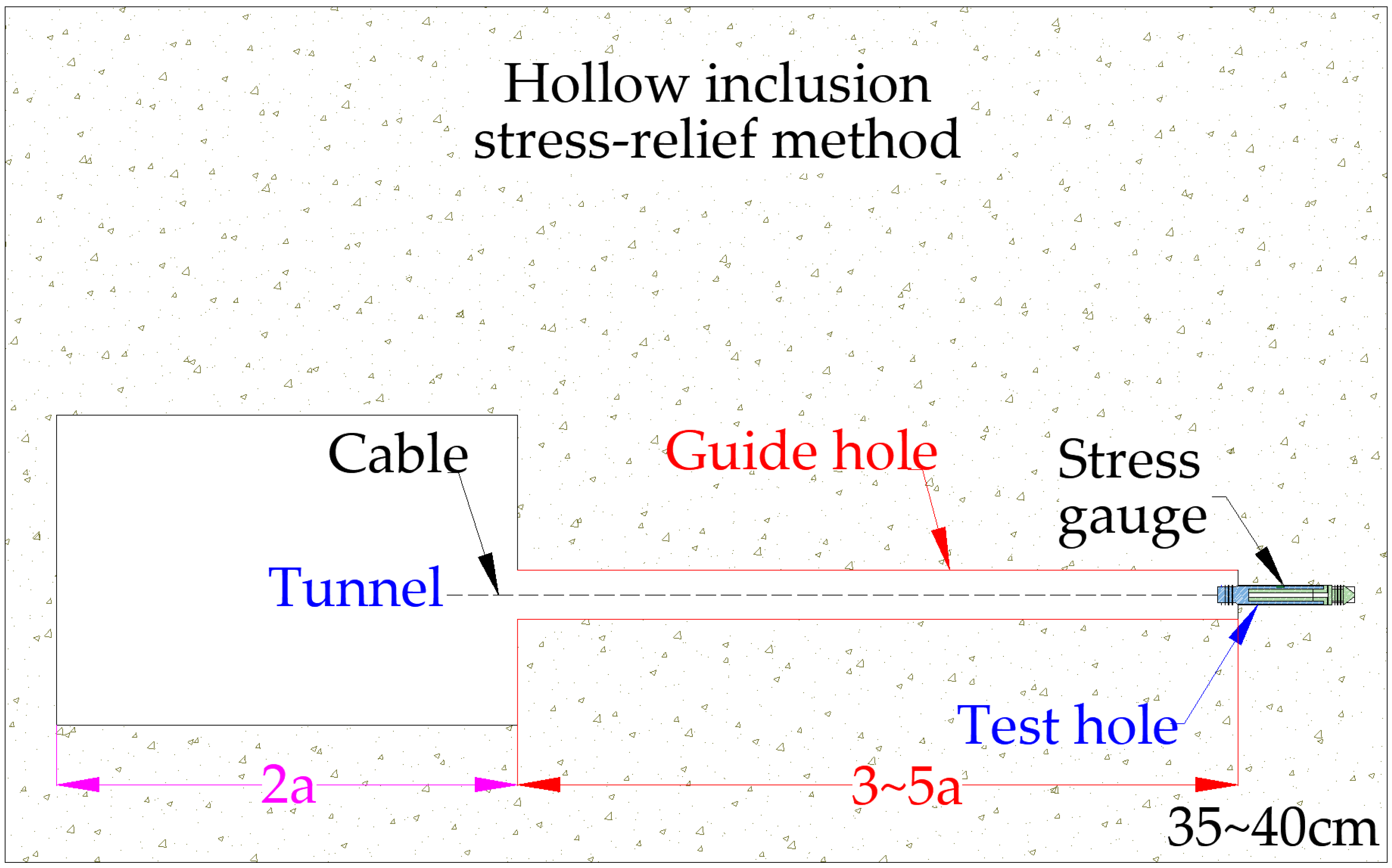
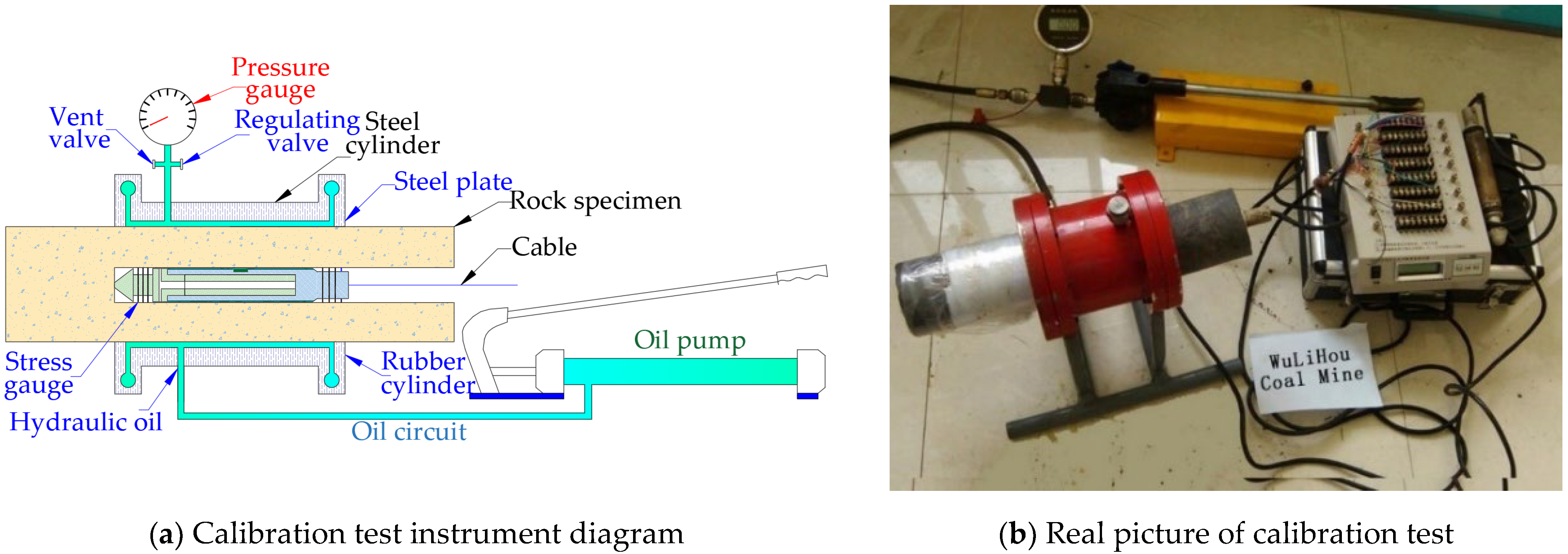
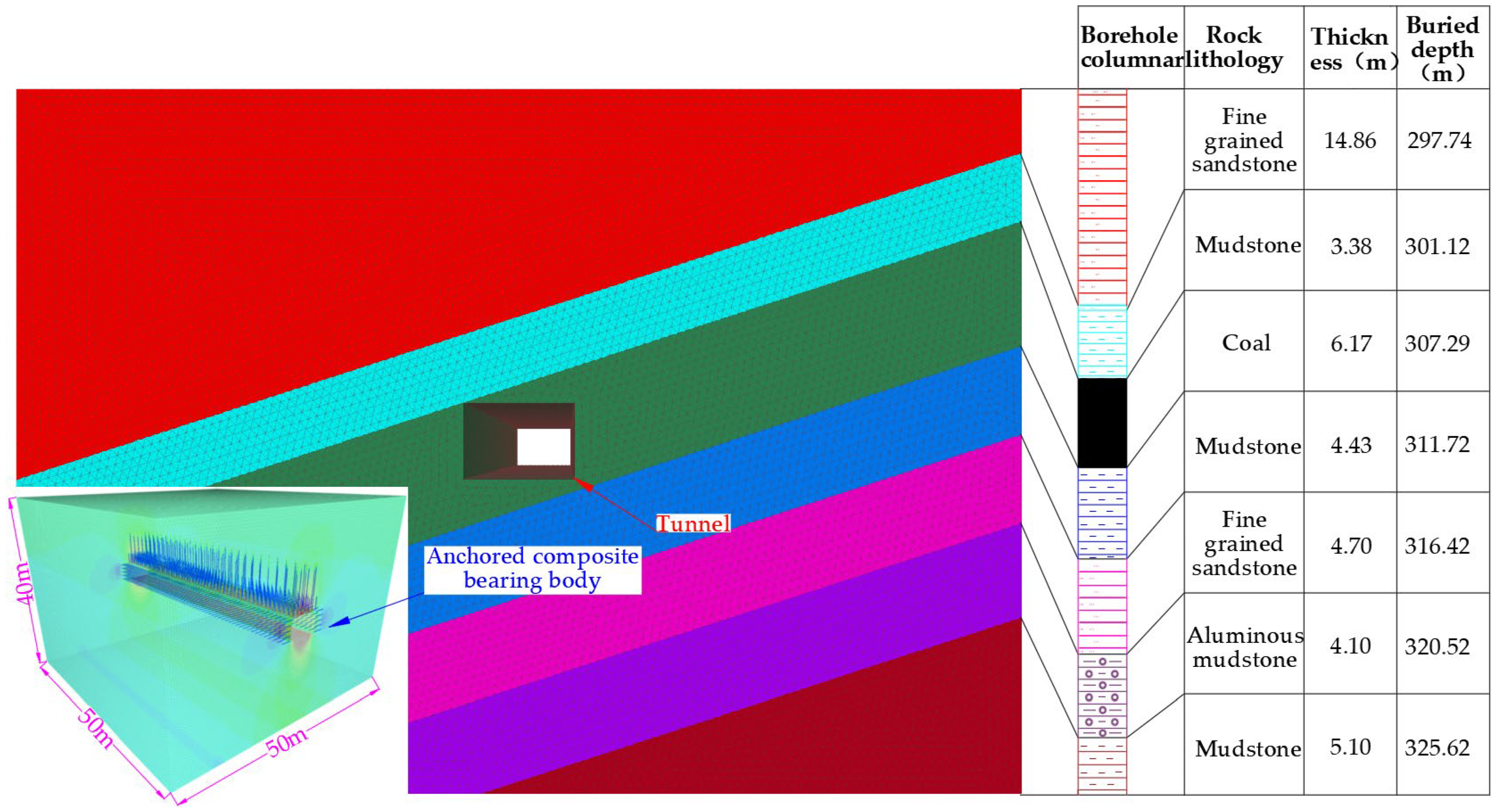
2. Site Engineering Overview and Geomechanical Testing

Shanxi Wulihu Coal Mining Co., Ltd., Jinzhong China. mined two groups of coal. Coal seam 15# was mined in the lower coal group, with a mine ground elevation of +1215 m, a working-face elevation of about +900 m, a buried depth of about 310 m, an average thickness of 6.17 m, inclination angles of 8–18°, and an average inclination angle of 16°. The immediate roof of coal 15# was 3.38 m mudstone; the main roof was 14.86 m fine-grained sandstone; the continuing upward was siltstone and mudstone. The direct floor of coal seam 15# was mudstone with a thickness of 4.43 m, and the main floor was fine-grained sandstone with a thickness of 4.70 m.
Figure 1 shows the concentrated belt transportation and return-air downhill of the lower group coal as well as the excavation along the inclined coal seam. The 2103 working face is located on the north side of the preparation roadway of the lower coal group and arranged along the strike of coal seam 15# (see Figure 2). The belt grooves of the 2103 working face are excavated along the roof. The east side is the ingenerated coal of the 2103 working face, and the west side has no working face currently.
It is necessary to master the main parameters of the lower coal group affecting the surrounding rocks of the roadway to control stability. Thus, a geomechanical test of the lower coal group was performed, including a mechanical property test of the surrounding rocks and an in situ stress test. The in situ stress test adopts the hollow-core cladding stress-relief method to test the in situ stress of the lower coal group. Figure 3 shows the hollow-inclusion stress gauge, which is composed of the cable, orientation pin, barrel sealing ring, epoxy resin cylinder, binder, strain rosette, fixing pin, plunger, guide rod sealing ring, and guide rod [21,22].
When ground stress was tested, guide holes and test holes in the roadway were drilled (see Figure 4). The depth of the pilot hole was generally more than twice the width of the roadway, and that of the test hole was 35–40 cm. A specific guide rod was used to install the hollow-inclusion stress gauge in the test hole after the test hole was drilled. The cable was connected to a specific strain gauge after the stress gauge and test hole were firmly bonded. A geological drilling rig was used to remove rock masses wrapping the hollow-core stress gauge, and the installation and removal conditions were recorded.
Data recorded by the strain gauge were saved after stress relief on the scene. Cores wrapped with hollow-inclusion stress were sent to the laboratory for calibration tests. The calibration tester, composed of an oil pump, oil circuit, cylinder barrel, and pressure gauge were used to accurately measure the elastic modulus and Poisson’s ratio of rock masses (Test equipment is shown in Figure 5, The test process is shown in Figure 5b).
The work sorted out the Poisson’s ratio, elastic modulus, borehole azimuth angle, borehole inclination angle, position angle of strain rosettes in group A, coefficient of the extruded glue amount, and strain-gauge reading difference of the rock masses after the calibration test. Above data were inputted into a specific STR DOS program to obtain the magnitude and direction of the in situ stress test [23]. A total of three regional tests were carried out in the lower coal group of the Wulihu Mine (see Figure 6 for test results).
The maximum principal stress of the lower group coal of the Wulihu coal industry is horizontal stress, with an average maximum principal stress of 18.5 MPa and a direction angle of N34.09°E. The minimum principal stress is still horizontal stress, with an average stress of 10.5 MPa and a direction angle of N123.32°E. The middle principal stress is vertical stress, with an average stress of 11.5 MPa and a direction angle of N217.39°E. The angle between the maximum principal stress and the axis of the roadway is 34°, and stress affects the stability of the surrounding rocks of the roadways.

3. Analysis of Non-Uniform Failure Characteristics of Inclined Coal Seams

The failure and deformation of the surrounding rocks of the roadway have a great correlation with the stress and losing development of the surrounding rocks after the roadway excavation in the inclined coal seams. The formation of the support system and the force of the support system are analyzed in this section to explore the non-uniform failure mechanism of the roadways of the inclined coal seams.

3.1. Loose, Fractured, and Anchored Composite Supporting Body of the Surrounding Rocks of the Roadway

The roadway excavation provides new space for surrounding rocks. The area closer to the rock surface of the roadway exhibits stress relief, and the area farther from the rock surface exhibits stress concentration. Fractures, fissures, and loose circles of surrounding rocks are formed under stress and roadway spaces (see Figure 7). The loose circle of surrounding rocks is the rupture zone from the palisades of the roadway inward, which is caused by the disturbance of the excavation project. Rock masses converge onto the roadway center under stress after the rupture zone. Fractures develop without complete rupture in the convergence process, which forms a fracture development zone. Surrounding rocks in the deeper area of the fracture development zone only suffer plastic failure but do not rupture under the support of the surrounding rocks in the fracture development zone and rupture zone. This is called the plastic zone [24,25,26].
The surrounding rocks of the roadway are supported by bolts and cables applied with pre-tightening force to maintain stability after the roadway excavation. The multiple bolt (cable) groups make broken soft rock masses within the anchorage range form a bearing structure with certain strength that is called the anchored composite supporting body. The internal friction angle and cohesion of the anchored composite supporting body are improved so that the stress state of the surrounding rocks changes. The expansion of the plastic zone of surrounding rocks is controlled, which reduces the deformation of the roadway. However, the anchored composite supporting body is affected by the inclined roof, which results in non-uniform damage. The non-uniform failure mechanism of the roadway is analyzed in the following.

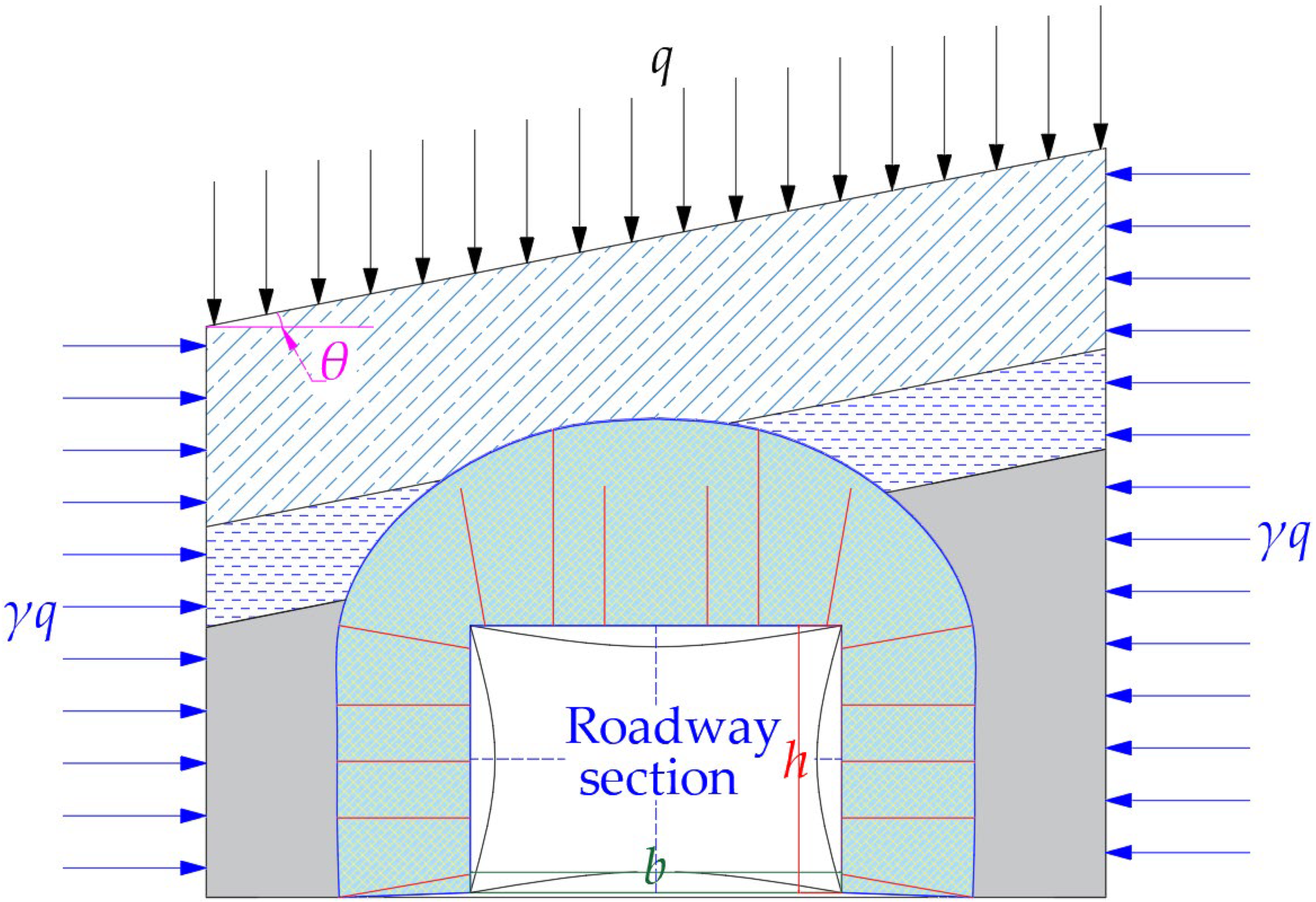
3.2. Stress Failure Analysis of Mining Roadways in Inclined Coal Seams

Inclined strata where roadways are located are affected by vertical and horizontal stress, and vertical stress is the hydrostatic pressure. Rock strata are inclined under tectonic stress, and stress in this area should be greater than that under normal conditions. Based on this background, the principles of roadway failure and deformations are analyzed.
The belt grooves of the 2103 working face of the lower group of the Wulihu coal industry are buried at a depth of about 310 m. According to Heim’s hydrostatic stress theory, the vertical stress that the roadway bears after being excavated in strata is
σ v = λ H
where λ is the bulk density of overlying rocks, 2500 kg/m3 and H the burial depth (m).
According to Equation (1), the vertical stress value σv is 7.75 MPa. The in situ stress test of the Wulihu coal industry is used to obtain that the vertical stress of the lower coal group is 11.5 MPa; maximum horizontal stress is 18.5 MPa; and minimum horizontal stress is 10.5 MPa. Horizontal stress, σh, can be taken as the intermediate value of 14.5 MPa; therefore, the lateral pressure coefficient is 1.26. The inclination angles of the lower coal group in the Wulihu coal industry are 8–18°, with an average value of 16°.
Figure 8 shows the established mechanical model, and the stress of the two sides and roof is redistributed after the roadway excavation. h, is the height of the roadway; b, the width of the roadway; q, vertical stress; γ, horizontal stress; and θ, the rocks’ inclination angle.
The stress of anchored composite supporting body is transmitted through inclined rock strata and can be divided into horizontal and vertical stress. F1 and F2 are the components of vertical and horizontal loads on rock strata, respectively [27].
F 1 = 0 b q cos θ d x = q b cos θ
F 2 = 0 h γ q sin θ d x = γ q h sin θ
The normal stress of inclined rock strata on anchored composite supporting body is F = F1 + F2. The in situ stress test results of the lower coal group of the Wulihu coal industry show that the vertical stress is 11.5 MPa, the lateral stress is 14.5 MPa, and the inclination angle of coal seam 15# is 16°. Based on the above theoretical analysis, the normal stress of rock strata is 15.04 MPa, the uniaxial compressive strength of triangular coal along the belt grooves of the lower coal group of the 2013 working face is 6.02 MPa, and the strength of roof mudstone is 48.96 MPa. The strength of anchored composite supporting body is improved after supporting, but the strength of coal seam 15# is small. Severe creep fractures occur with time, whereas mudstone strength is relatively large, and creep fractures are relatively slight.
The mechanical model of the clamped beam (see Figure 9) is established to explore the failure positions of the surrounding rocks of the roadway. qz(x) is the normal uniform load on the fixed beam in the model; the length of the rock beam is set to l; l is the projected length of anchored composite supporting body on inclined rock strata.
According to elastic mechanics and material mechanics, the bending moment equation of the rock beam is
M ( x ) = q l 2 x q 2 x 2 F w
where qz(x) is the normal component of horizontal and vertical stress in inclined rock strata and w the deflected line of the rock mass beam. Then,
d 2 w d x 2 = M E I = q l x 2 E I q 2 E I x 2 F w E I
Let k 2 = F E I , and substitute it into Equation (4) to obtain
w + k 2 w = ( q 2 F l x q 2 F x 2 ) k 2
Its general solution is
w = A sin k x + B cos k x q 2 F x 2 + q l 2 F + q F k 2
The integration constant is determined by boundary conditions. When x = 0 and w = 0, B = q F k 2 .
When x = l 2 and w′ = 0, A = q F k 2 tan k l 2 .
The deflection equation of the rock-mass beam is obtained as
w = q F k 2 ( 1 cos k x tan k l 2 sin k x ) q 2 F ( l x x 2 )
Equation (7) is substituted into bending moment Equation (3) to obtain the bending moment equation.
M ( x ) = q F k 2 ( 1 cos k x tan k l 2 sin k x )
Equation (9) shows that the maximum deflection occurs at x = l 2 , that is, the most serious failure area of the roadway is the center of the inclined roof. However, triangular coal areas exist on the roof and floor of the roadway. The distances between the mudstone on the roof and floor and the coal seam are different, but the failure of coal masses in the surrounding rocks is more serious than that of rock masses. Therefore, surrounding rocks present non-uniform failure and deformations. Numerical simulation software is now used to study plastic failure, stress distribution, and displacement of the surrounding rocks of the roadway, which verifies the above analysis results.

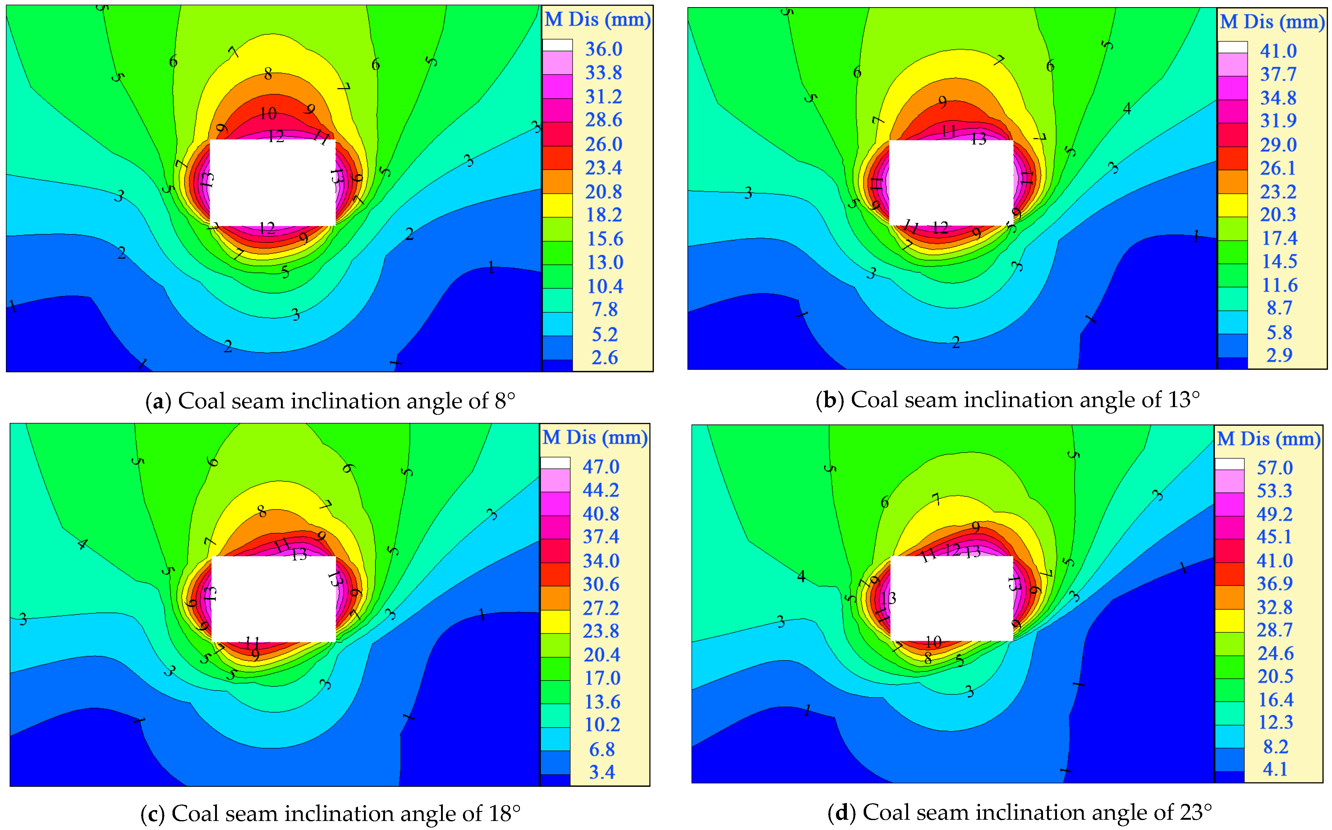
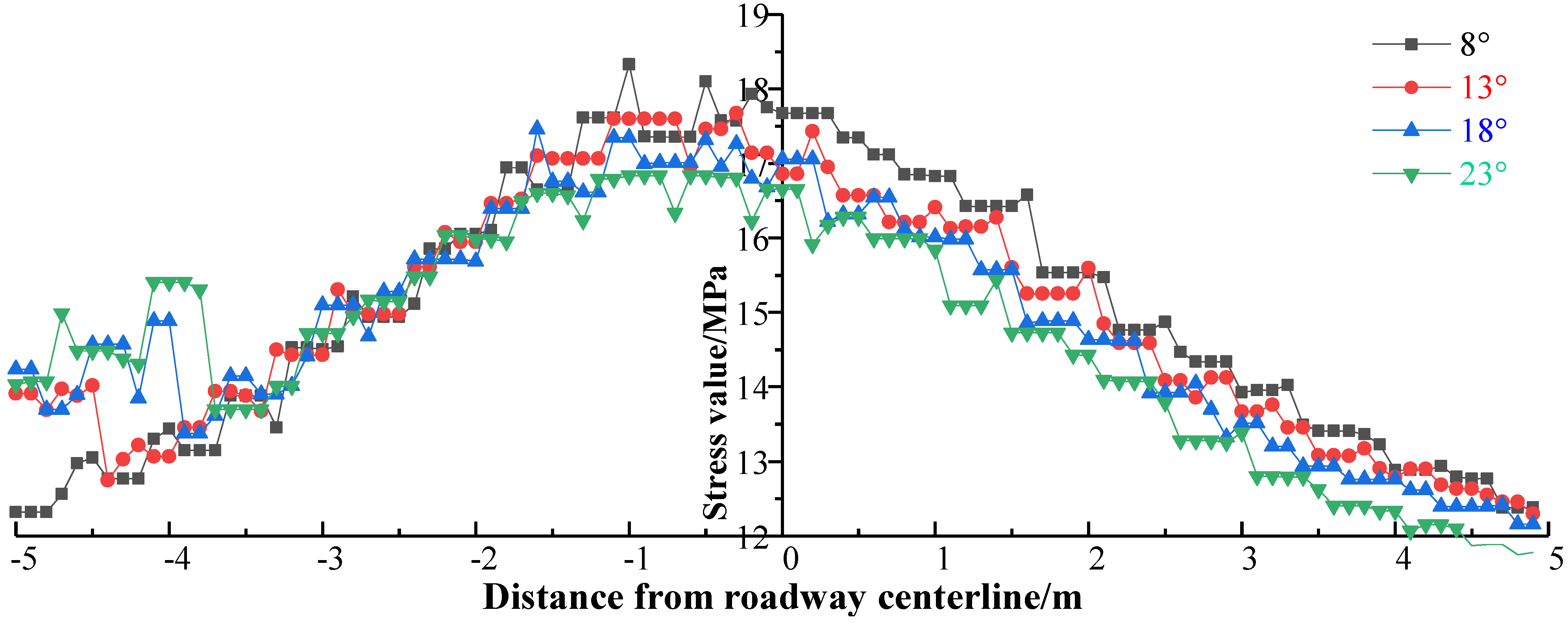
4. Numerical Simulation Analysis of the Failure of Roadways

Finite-difference numerical simulation software FLAC6.0 was used according to the geological conditions of the 2103 working face in the lower coal group of the Wulihu coal industry. A 3D numerical model with 50 × 50 × 40 m (L × W × H) was established to simulate the non-uniform failure characteristics of the mining roadway in inclined strata. The model adopted Rhino5.0 for modeling and the Griddle plug-in to divide grids [28]. The bolts and cables of the roadway in the simulation were divided in advance by Rhino5.0, with the formatted file (dxf) exported. A stress of 11.5 MPa was applied to the roof to simulate the bulk density of overlying rocks, and a lateral stress of 14.5 MPa was applied around it. The dxf file was directly imported to the FLAC3D model as bolts and anchor cables, and parameters were assigned in the simulation process. A survey line was arranged at 1.5 m of the floor to record the stress value. Figure 10 shows the numerical simulation model, and Table 1 shows the specific distribution of the overlying strata and the floor and the corresponding mechanical parameters of rocks.
A total of four models are established in this simulation, and the inclination angles of modeled rock formations are 8, 13, 18, and 23°, respectively. The roadway is excavated first, and then the bolts and anchor cables are laid in the simulation process. The stress contour, plastic zone, and displacement are derived (see Figure 11, Figure 12 and Figure 13) after the equilibrium is calculated.
Free space appears in the original compacted area after the roadway is excavated. Original rock stress is redistributed (see Figure 12 for regional minimum stress distribution), and the area closer to the roadway surface shows stress relief. The stress-relief area on the roof is biased toward the high side of rock strata, and that on the floor is biased towards the lower side. Stress in the area far from the roof and floor of the roadway gradually recovers to or closes to the original rock stress. The area farther from the two sides of the roadway is characterized by stress accumulation. Stress accumulation in the surrounding rocks of the roadway in the upper rock-stratum area is greater than that in the lower rock-strata area. Stress relief in the stress-relief area is obvious with the increased inclination angle of the rock strata. The accumulation amount in the stress accumulation area is large, with a maximum stress accumulation value of 18.8 MPa and a stress concentration coefficient of 1.30.
Coal and rock masses suffer tensile and plastic failure under stress after the roadway excavation. The tensile failure is not obvious, and the main performance is plastic failure under the anchored composite supporting body. The plastic areas of the two sides of the roadway have little change, and the plastic failure of the roof and floor changes greatly at different inclination angles. As the inclination angle of the rock strata increases, the failure of the high side of the roof and the low side of the floor is aggravated, and that of the high side of the floor is weakened. The plastic failure area mainly occurs in the coal masses, and the plastic failure of the immediate roof and floor of mudstone is relatively minor. The boundary of the plastic failure area is relatively clear, which is consistent with the boundary line of coal and rock masses.
Stress is redistributed after the roadway is excavated, and coal and rock strata are damaged under stress. Damaged strata cannot maintain their original shape and move to the free space, which causes the roadway to deform (See Figure 13). The roadway shows uniform deformation in the horizontal or near-horizontal rock strata, and the largest deformation occurs on the roof, floor, and in the middle area of the two sides. Non-uniform deformation occurs in inclined rock strata. The maximum position of roof deformation is shifted from the roadway centerline to the high-side area, and the maximum floor deformation position is shifted from the roadway centerline to the low-side area. The maximum deformation position of rock strata on the low side of the roadway is shifted downward from the center, and that on the high side is shifted upward from the center. The overall deformation of the roadway increases with the increased inclination angle of rocks, and non-uniform failure is more obvious.

5. Discussion of Research Results

The surrounding rocks of the roadway can be divided into six areas (see Figure 14) by simulating the failure and deformation law of the mining roadway of the inclined coal seams above. The roof of the roadway is divided into areas I and IV, the floor is divided into areas III and IV, and the two sides are divided into areas I and V.
Coal masses exist on both sides of the roadway, and areas II and V are on the high side of the inclined rock strata. The shearing action of the inclined rock strata in area II is more serious than that in area V, which is one of the reasons for the non-uniform failure of the roadway. Coal masses occupy a larger proportion of area I than of area VI on the roof and floor of the roadway. Compared with area III in the floor, coal masses occupy a larger proportion of area IV, with the large stress of the roadway. Severe creep failure occurs in the coal masses under high stress, and the failure of rock masses is relatively slight. Therefore, failure in areas I and IV is more serious, and the damaged coal masses are easily deformed, which is the main reason for the non-uniform damage and deformations of the roadway. It is necessary to take corresponding reinforcement and pressure relief measures in areas I, II, and IV, based on the original support technology to control the non-uniform failure and deformations of inclined rock strata.

6. Measurement of the Non-Uniform Failure Control Technology and Application Effects of Inclined Rock Strata

Aiming at the special geological conditions of the inclined coal seams where the belt grooves are located along the 2103 working face of the Wulihu coal industry, as well as the above theoretical analysis and numerical simulation research results, the work proposed the technical measures of pressure-relief grooving, strengthening support, and grouting reinforcement for the non-uniform failure of the large-section mining roadway in the inclined coal seams. Areas I, II, and IV were subjected to grouting reinforcement, full-length anchoring support, and pressure-relief grooving, respectively. The position of pressure-relief grooving is the most important for controlling the deformation of the floor, and X-axis stress perpendicular to the roadway axis has the greatest effect on the deformation of the floor. To this end, stress data arranged in the X-axis of the survey line of the roadway floor were derived to draw a line graph (see Figure 15).
The stress value of the roadway floor in the inclined coal seams decreases with the increased inclination angle, and the maximum stress value shifts to the lower side of inclined rock strata. The maximum floor stress offsetting the centerline increases with the increased inclination angle of the coal seam. The maximum stress is about 1 m away from the roadway centerline, so it is most suitable for the pressure-relief groove to be 1 m away from the centerline of the roadway floor.
Grouting reinforcement is adopted in area I of the roadway roof. The grouting reinforcement of coal and rock masses can tightly bond coal seams and rock strata together [29,30,31,32]. The grouting diffusion radius is about 1.6 m, and two rows of grouting holes can be set. The first and second rows are 0.9 and 1.8 m away from the roadway centerline, respectively. The row spacing is 0.9, and the row spacing of grouting holes is consistent with that of the anchor cable. The bolts on the side are increased by 200 mm based on the original bolts.
The feasibility of the technical solution should be verified through numerical simulations to ensure the stability and reliability of the engineering effect. The inclination angle (16°) of rock strata in modeling is set as the mean value of the rock-stratum inclination angle of the Wulihou coal industry (see Figure 16).
The original support scheme of the belt grooves of the 2103 working face of the lower coal group of the Wulihu coal industry is as follows. The spacing between the rows is 850 × 900 mm with seven bolts in each row of the top plate. The row spacing between anchor cables is 2000 × 1800 mm with three anchor cables in each row. The row spacing is 850 × 900 mm with five bolts in each row of the side. Left-hand-threaded steel bolts without longitudinal reinforcement are on the forward left side, and full-threaded bolts of glass fiber reinforced plastic are on the forward right side. Two resin anchorage agents are used in each row of the side, and bolts and anchor cables are supported by steel ladders and wire meshes. Combined with the previous theoretical analysis and numerical simulation research results, areas I, II, and IV are subjected to grouting reinforcement, full-length anchoring support, and pressure-relief grooving, respectively. The feasibility of the scheme is verified through numerical simulations (see Figure 17 for the new support scheme).
The average inclination angle of the lower coal group is 16°. Area I is grouted for reinforcement, with two grouting holes in each row. The first row of holes is 1300 mm deep and 900 mm from the roadway centerline; the second row of holes is 1500 mm deep and 1800 mm from the centerline. The grouting material is Jinan Reinforcement 1#. The bolts in area II are supported by full-length anchoring, and the number of anchoring agents is increased from two to three for each. Pressure-relief grooving is performed in area IV, and the pressure-relief groove is 1600 mm away from the left side of the roadway with a groove depth of 1500 mm and a width of 500 mm. Other support patterns remain the same as the original support patterns. Two surface displacement monitoring stations are set up along the belt grooves of the 2103 working face to test the effects of field applications (see Figure 18 and Figure 19 for the monitoring results).
Surrounding-rock stress increases after the roadway excavation. The roadway deforms slowly under the mine pressure. When it is excavated to about 50 m, the convergence of the roof and floor of the roadway is about 21 mm, and that of the two sides is about 30 mm. Surrounding rocks are deformed under stress and disturbances with the excavation of the working face. When the working face is about 85 m away from the measuring point, the roadway enters the stable deformation period. The roof and floor convergence of the roadway is about 65 mm, and the convergence of the two sides is about 85 mm. The roadway deformations are the same as the numerical simulation results, with small overall deformations. The technical effects of grouting reinforcement, strengthening supports, and pressure-relief grooving proposed in the work are remarkable in controlling the mine pressure and rock strata

7. Conclusions

The engineering geological conditions of the lower coal group in the Wulihu coal industry were analyzed through the in situ stress test, theoretical analysis, numerical simulations, and field measurement to obtain the following conclusions.
(1)
The broken zone of surrounding rocks formed an anchoring composite supporting body with the support system under stress and disturbances after the roadway was excavated. The anchoring composite supporting body could improve the mechanical properties of the support system and ensure the stability of the surrounding rocks of the roadway.
(2)
The proportions of coal and rock masses in different regions of the surrounding rocks were quite different in the roadway of inclined coal seams. The mechanical properties of the support system were improved under the anchored composite supporting body; however, the mechanical strength of coal masses was small. Different creep failure occurred in coal and rock masses under high stress, which results in non-uniform failure of the roadway.
(3)
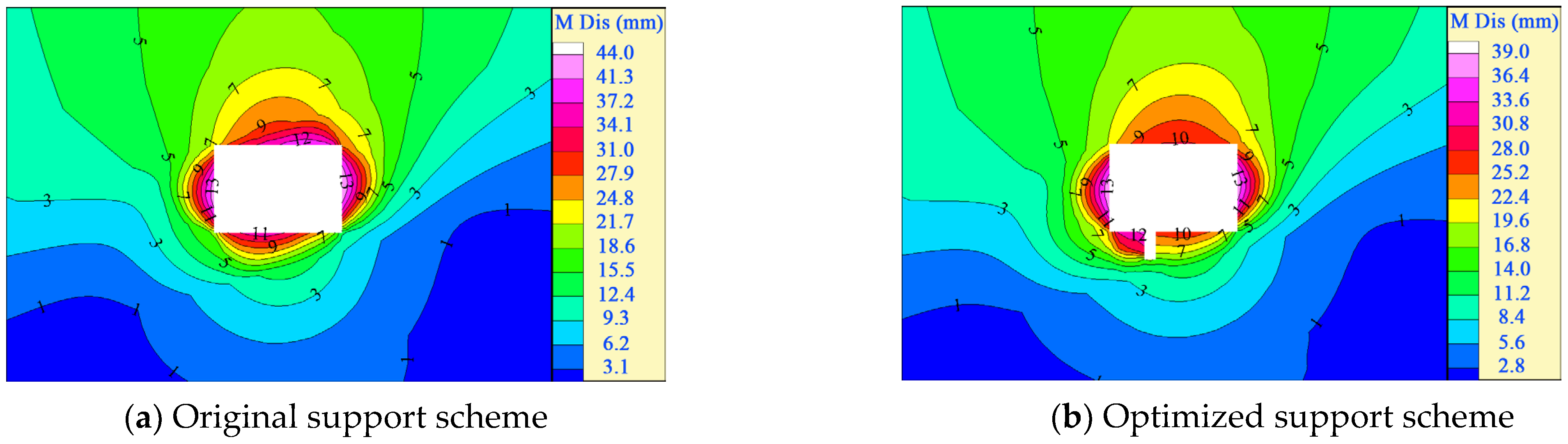
The damaged area of the roof showed that the centerline was inclined to the high side, and that of the floor presented that the roadway centerline was inclined to the low side. There were some differences between the two sides. The technical measures for grouting reinforcement, strengthening support, and pressure-relief grooving were put forward and verified by numerical simulations.
(4)
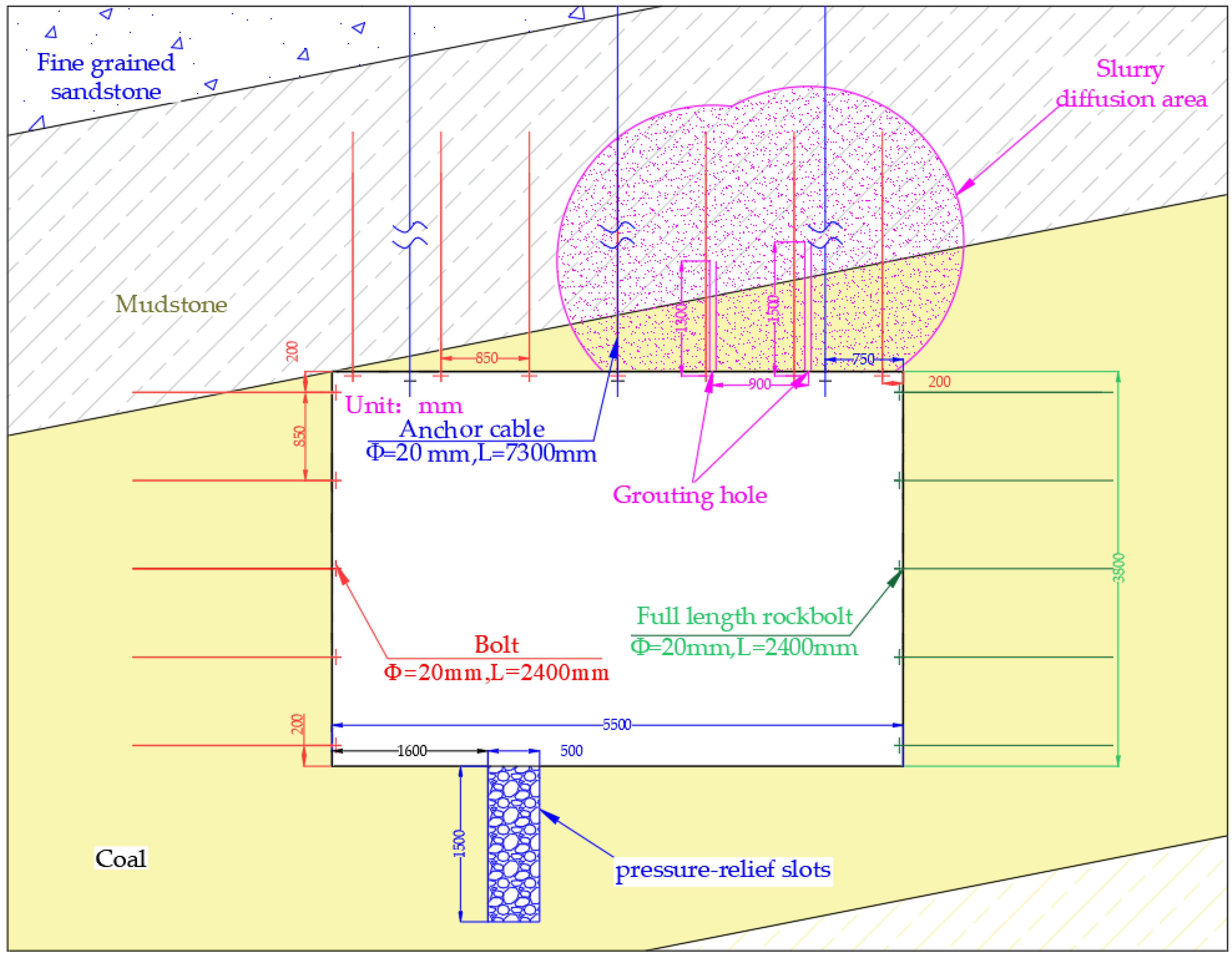
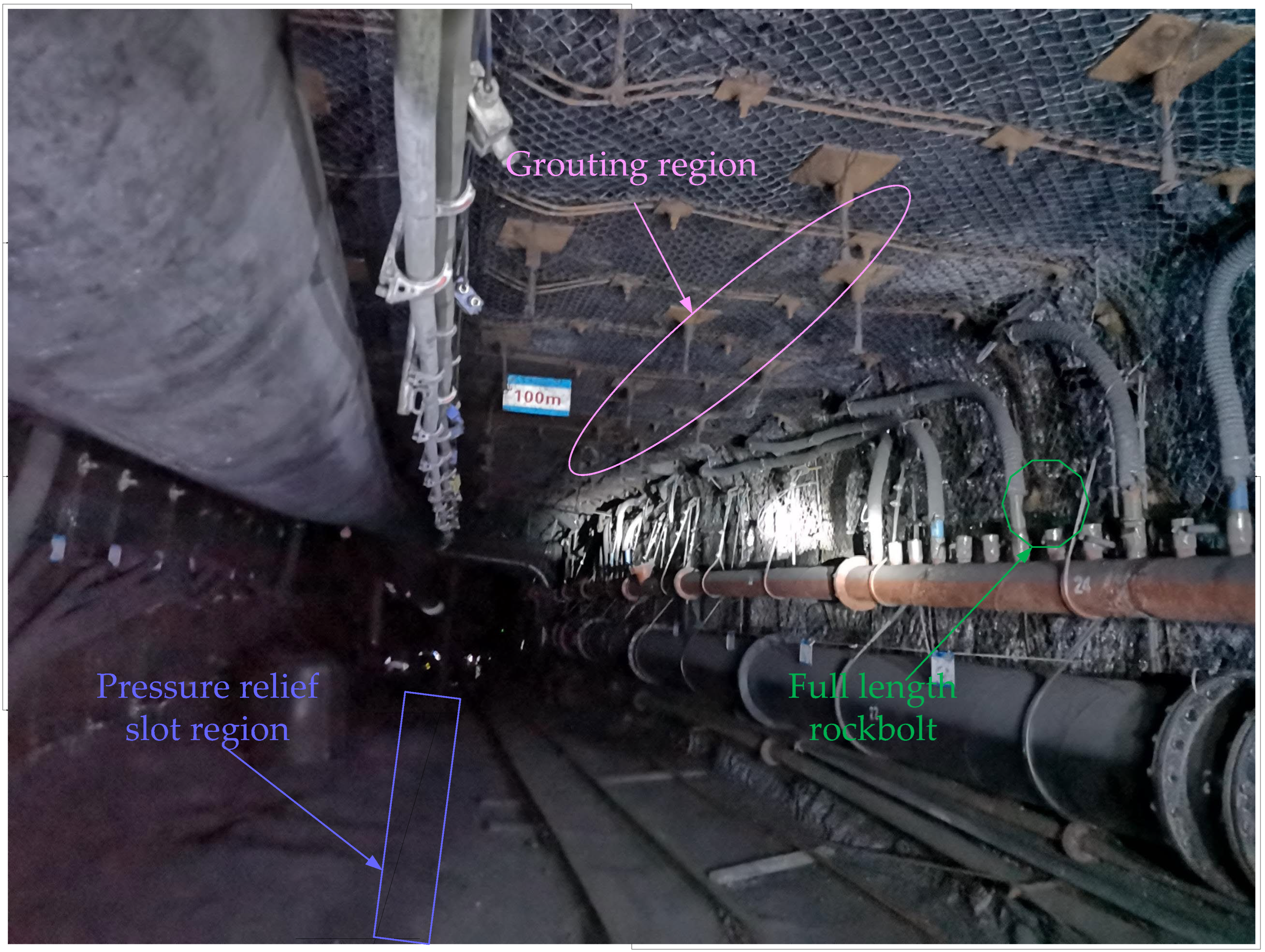
The roof adopted double-hole grouting. The depth of grouting holes was 1300 and 1500 mm, with a spacing of 900 mm and a row spacing of 1800 mm. The pressure-relief groove was located in the area where the roadway centerline was inclined to the 1000 mm area of the low side, with a groove depth of 1500 mm and a width of 500 mm. The field application effect is good, which provides a reference for similar projects.

Author Contributions

Conceptualization, Q.M. and Y.Z.; methodology, J.C.; software, Z.L. and X.Z.; validation, G.S. and Q.M.; writing—original draft preparation, Q.M.; writing—review and editing, K.G. and Q.M.; project administration, Y.Z. All authors have read and agreed to the published version of the manuscript.

Funding

This work was funded by the Key Project of Joint Funds of the National Natural Science Foundation of China (Grant No. U1903209) and the Shandong Province Key Laboratory of Mine Mechanical Engineering (Grant No. 2019KLMM205). The authors gratefully acknowledge the financial support of the above-mentioned agencies.

Institutional Review Board Statement

Not applicable.

Informed Consent Statement

Not applicable.

Acknowledgments

The authors would like to thank the engineering technicians in Shaping Coal Mine for their enthusiastic assistance and suggestions.

Conflicts of Interest

The authors declare no conflict of interest.

References

  1. Zhang, T. Discussion on the Current Situation and Development Trend of Energy Utilization in China. Territ. Nat. Resour. Study 2021, 5, 76–78. [Google Scholar]
  2. Zheng, C.; Zhang, Y.; Long, L. Study on National Principal Energy Consumption Structural Modulation and Optimization in New Era. Col. Geo. Chi. 2021, 33, 49–51. [Google Scholar]
  3. Hou, C.J. Roadway Surrounding Rock Control; China University of Mining and Technology Press: Xuzhou, China, 2013. [Google Scholar]
  4. Xu, B. Research on the Occurrence Law of Rock Pressure and Surrounding Rock Control Mechanism in the Mining Roadway of the Gently Inclined Thin Coal Seams; Chongqing University: Chongqing, China, 2017. [Google Scholar]
  5. Zhao, D.; Xu, T.; Liu, W. Calculation of Bed Separation Under Horizontally and Generally inclined Coal Seam Mining. China J. Rock Mech. Eng. 2005, 24, 5767–5772. [Google Scholar]
  6. Zhao, S.; Wang, X.; Fan, G. Pillar size optimization design of isolated island panel gob side entry driving in deep inclined coal seam-case study of pingmei No.6 coal seam. J. Geophys. Eng. 2019, 15, 15. [Google Scholar]
  7. Wang, X.F.; Wang, Y.; Zhang, D.S. Enhanced support technology for key area of the roadway in large inclined angle “three-soft” coal seam. J. Min. Saf. Eng. 2017, 34, 6. [Google Scholar]
  8. Ma, L. Support stability mechanism in a coal face with large angles in both strike and dip. J. S. Afr. Inst. Min. Met. 2015, 115, 599–606. [Google Scholar] [CrossRef]
  9. Liu, K. Research and Application of Coal Wall Stability in Fully Mechanized Face with Large Inclination Angles and High Mining Heights; Xi’an University of Science and Technology: Xi’an, China, 2017. [Google Scholar]
  10. Kulakov, V.N. Stress state in the face region of a steep coal bed. J. Min. Sci. 2015, 9, 161–168. [Google Scholar] [CrossRef]
  11. Jawed, M.; Sinha, R. Design of rhombus coal pillars and support for roadway stability and mechanizing loading of face coal using SDLs in a steeply inclined thin coal sea ma technical feasibility study. Arab. J. Geo 2018, 15, 415. [Google Scholar] [CrossRef]
  12. Chen, J.; Yan, R.; Liu, K. Asymmetric sefor mation mechanism of roadway at steeply inclined thick coal seam. J. China Coal Soc. 2018, 43, 3007–3015. [Google Scholar]
  13. Zhang, J. The fracture mechanism of main roof stratum and strong mine pressure control method in long wall mining of steeply inclined coal seam in Wangjiashan colliery. Chin. J. Rock Mech. Eng. 2018, 37, 1776. [Google Scholar]
  14. Zhang, W.; He, Z.M.; Zhang, D.S. Surrounding rock deformation control of asymmetrical roadway in deep three—soft coal seam: A case study. J. Geophys. Eng. 2018, 15, 1917–1928. [Google Scholar] [CrossRef] [Green Version]
  15. Wu, H. Non-Uniform Deformation Evolution Law and Stability Control of the Roadway in the Deep Inclined Rock Strata; China University of Mining and Technology: Xuzhou, China, 2014. [Google Scholar]
  16. Gale, W. Stress distributions and rock failure around coal mine roadways. Int. J. Rock Mech. Min. Sci. Géoméch. Abstr. 1987, 24, 165–173. [Google Scholar] [CrossRef]
  17. Gale, W. Strata control utilizing rock reinforcement techniques and stress control methods, in Australian coal mines. International. Min. Eng. 1991, 150, 247–253. [Google Scholar]
  18. Yang, H.; Bai, J.; Wang, X. Soft roof failure mechanism and supporting method for gob—Side entry retaining. Minerals 2015, 5, 707–722. [Google Scholar] [CrossRef]
  19. Wang, M.; He, Z.; Zhang, D. Stability and control technology of overlying structure in gob-side entry driving roadways of deep inclined coal seam. J. Min. Saf. Eng. 2015, 32, 426–432. [Google Scholar]
  20. Chen, X.; Wang, M. Research on surrounding rock deformation characteristics of gob-side entry driving in deep inclined coal seam and its control technology. J. Min. Saf. Eng. 2015, 32, 485–490. [Google Scholar]
  21. Gao, H.; Yang, S.; Liu, X. Hollow Inclusion In-situ Stress Test Method and Engineering Application. Coal Eng. 2015, 47, 4. [Google Scholar]
  22. Cai, M.F. Rock Mechanics and Engineering; Science Press: Beijing, China, 2022. [Google Scholar]
  23. Guo, Q.L.; Yang, S.X. Specification of Hydraulic Fracturing and Overcoring Method for In-Situ Stress Measurement DB/T 14-2018; China Seismological Bureau: Beijing, China, 2018. [Google Scholar]
  24. Zhang, Y.D. Research on the Bearing Characteristics of the Anchored Composite Bearing Body and Its Application in the Design of Roadway Bolt Supports; China University of Mining and Technology: Xuzhou, China, 2013. [Google Scholar]
  25. Cheng, L. Influence Law of Bolt Length on Bearing Characteristics of Anchored Composite Carrier and Study on Length Design; China University of Mining and Technology: Xuzhou, China, 2014. [Google Scholar]
  26. Zhang, Y.; Cheng, L.; Yang, J. Bearing Characteristic of Composite Rock-bolt Bearing Structure Under Different Bolt Support Density. J. Min. Saf. Eng. 2015, 32, 6. [Google Scholar]
  27. Dong, Y.X. Research on Asymmetric Deformation Mechanism and Control Technology of the Roadway in Inclined Soft Coal Seams; China University of Mining and Technology: Xuzhou, China, 2019. [Google Scholar]
  28. Zhang, Y.Z. Chinese Rhino 5.0 Complete Practical Technical Manual; Tsinghua University Press: Beijing, China, 2016. [Google Scholar]
  29. Xu, Y.C.; Yang, Y. New Progress on Floor Grouting Reinforcement Technology of Water Control in Coal Mining Face. Coal Sci. Technol. 2014, 42, 98–101, 120. [Google Scholar]
  30. Du, X.W. Research on Surrounding Rock Stability and Control Technology of Gob-Side Entry Retaining in the Fully Mechanized Caving Face of Gaohe Energy; China University of Mining and Technology: Xuzhou, China, 2019. [Google Scholar]
  31. Huang, D.F.; Wang, Z.M.; Yang, B. Construction technology of formation grouting water blocking and reinforcement. Chi. Uni. Min. Tecy. Pre. 2003, 1. [Google Scholar]
  32. Wang, P.; Ye, S.F.; Wang, H. Omni-directional Comprehensive Grouting Reinforcement Technology for Underground Tunnel. Saf. Coal Min. 2013, 4, 3. [Google Scholar]
Figure 1. Relationship between coal seam 15# and the preparation roadway.
Processes 10 01993 g001
Figure 2. Plan of mining engineering.
Processes 10 01993 g002
Figure 3. Hollow—inclusion stress gauge.
Processes 10 01993 g003
Figure 4. Test of the stress-relief method.
Processes 10 01993 g004
Figure 5. Calibration test instrument.
Processes 10 01993 g005
Figure 6. In situ stress test results.
Processes 10 01993 g006
Figure 7. Model of loose and anchored composite supporting body of surrounding rocks.
Processes 10 01993 g007
Figure 8. Stress of the mining roadway in the inclined coal seams.
Processes 10 01993 g008
Figure 9. Bending deformation model of the rock beam.
Processes 10 01993 g009
Figure 10. Numerical simulation model.
Processes 10 01993 g010
Figure 11. Distribution of minimum regional stress.
Processes 10 01993 g011
Figure 12. Development of excavated plastic area of the roadway with different inclination angles.
Processes 10 01993 g012
Figure 13. Cloud map of the overall displacement of the roadway excavation with different inclination angles.
Processes 10 01993 g013
Figure 14. Division of the surrounding-rock areas of the roadway in inclined rock strata.
Processes 10 01993 g014
Figure 15. Line chart of X-axis stress of the roadway floor.
Processes 10 01993 g015
Figure 16. Implementation of the surrounding-rock control technology of the roadway.
Processes 10 01993 g016
Figure 17. Support scheme of a large-section roadway of gently inclined soft coal seams.
Processes 10 01993 g017
Figure 18. Line chart of surrounding-rock deformation of the roadway.
Processes 10 01993 g018
Figure 19. Field applications.
Processes 10 01993 g019
Table 1. Mechanics parameters of rocks.
LithologyH
(m)
D
(kg·m−3)
CS
(MPa)
B
(GPa)
TS
(MPa)
S
(GPa)
C
(MPa)
F
(°)
Fine-grained sandstone2972631114.4813.854.323.046.3943.99
Mudstone301252848.966.111.521.212.7634.2
15 coal seam30714685.500.750.180.171.1228
Mudstone4.4252630.43.001.380.842.3132.14
Fine-grained sandstone4.7262466.4312.167.012.078.3841.22
Note: H: buried depth of rock strata; D: density; CS: compressive strength; B: bulk modulus; TS: tensile strength; S: stress; C: cohesion; F: friction.
Publisher’s Note: MDPI stays neutral with regard to jurisdictional claims in published maps and institutional affiliations.

