Abstract
This article presents the most valuable and applicable open-source tools and communication technologies that may be employed to create models of production processes by applying the concept of Digital Twins. In recent years, many open-source technologies, including tools and protocols, have been developed to create virtual models of production systems. The authors present the evolution and role of the Digital Twin concept as one of the key technologies for implementing the Industry 4.0 paradigm in automation and control. Based on the presented structured review of valuable open-source software dedicated to various phases and tasks that should be realised while creating the whole Digital Twin system, it was demonstrated that the available solutions cover all aspects. However, the dispersion, specialisation, and lack of integration cause this software to usually not be the first choice to implement DT. Therefore, to successfully create full-fledged models of Digital Twins by proceeding with proposed open-source solutions, it is necessary to make additional efforts due to integration requirements.
1. Introduction
Digital transformation of manufacturing processes and production management is experiencing the influence of the development of flexible manufacturing systems by applying advanced information and communication technologies (ICT) in production automation [1]. These innovations shape a new paradigm of production systems, which is known as the Industry 4.0 (ger. Industrie 4.0) framework. Industry 4.0 (I4.0) is a collective term for the technology and concept of a value chain organisation, which includes four key elements [2]: Smart Factories, Cyber-Physical Systems (CPS), Internet of Things (IoT), and Internet of Services (IoS). The production organisation following the I4.0 framework can be considered as the information-driven flow of the workpieces machine-by-machine in a workshop floor, supported by real-time communication between machines and the manufacturing execution system (MES). The term cyber-physical systems (CPS) has been defined as “the systems in which natural and human-made systems (physical space) are tightly integrated with computation, communication and control systems (cyberspace)” [2]. By integrating the computational (cyber) world and physical world, CPS can bring autonomous control, self-awareness, and self-management capabilities to industrial machines. Integration can be considered as a four-stage evolutionary process [3], presented in Figure 1. There are no information systems involved in shop-floor processes at the first stage. At the second stage, industry evolutionary systems developed manufacturing planning and control systems [4]:
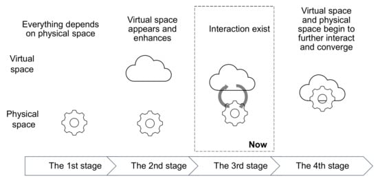
Figure 1.
Convergence of shop floor. Source: [4].
- Reorder point (ROP) systems;
- Materials requirement planning (MRP) systems, due to production integration;
- Manufacturing resource planning (MRP-II) systems, due to quality improvement;
- MRP-II with manufacturing execution systems (MES), due to time-based competition;
- Enterprise resource planning systems (ERP) with MES, due to global competition;
- Extended ERP (ERP II) with MES (internet).
The transition from the second to third stage started in the 2000s with the introduction of computer-integrated manufacturing (CIM) systems due to a digitalisation of machine tools (CNC) and product development (CAD/CAE/CAM). Currently, the industry is at the third stage: emerging IoT solutions and Big Data analysis introduce increasing interaction between virtual and physical spaces. The transition to the fourth stage is driven by the development of Digital Twins (DT), based on intensive two-way interaction due to growing possibilities for cyber-physical and information systems.
Designing modern equipment and industrial processes supporting digital convergence of a shop floor requires the development of virtual models necessary to check the correctness of assumptions and optimise the assumed parameters. Therefore, the Digital Twin is considered one of the essential concepts supporting the implementation of the abovementioned convergence.
Creating a Digital Twin requires specialised software tools to develop a virtual process model, simulation, optimisation, and visualisation. Commercial software packages like Emulate3D, iTwin, Forge, Seebo Digital twin are primarily employed to develop and implement Digital Twins in the industry. However, in the case of complex models using 3D graphics, modelling dynamic processes, allowing communication with the environment, and visualising process variables, these tools must be highly developed, making them very expensive for users. An alternative approach that reduces the costs of creating such systems can be done by applying software available under open-source licenses. Using open source in the development process has many advantages, including increased time to market, reduced cost of ownership, and improved software quality. Moreover, the value of open-source software is grounded in some fundamental, inherent properties, recognised in the software industry as applicable in the areas of [5]:
- Seeking different perspectives to make better software. Open source is about collaborative knowledge development that allows the global context of users and developers;
- Finding the balance between policy and autonomy. It requires introducing new policies to encourage employees to use, contribute to, and release open-source software in software companies;
- Securing every link in the supply chain. Community-driven process of development brings the risk of security vulnerabilities, but in return gives an uncentralised, flexible reaction to arising issues supported by initiatives of software companies like GitHub, Google, IBM, and others;
- Over-communication to support collaborative culture. Using open-source solutions exposes multi-channel communication inside and outside of the company and decreases the uncertainty.
However, the issue is finding and choosing the best programs and libraries that will be functional equivalents of commercial solutions and will allow for practical work.
The second chapter presents the evolving Digital Twin concept in the literature and in practice. Digital Twin’s development and implementation aspects with applying selected open-source software tools are presented in the third chapter. The fourth chapter presents libraries for 3D visualisation of Digital Twins. The fifth chapter is on communication methods used in industrial automation systems applied to Digital Twin modelling. Control systems modelling presented in the sixth chapter is crucial for Digital Twinning usability and applicability. Finally, the seventh chapter summarises the authors’ point of view on the applicability of open-source software and perspectives of Digital Twin concept implementation.
2. Digital Twin Concept
The idea of digital representation of physical objects for manipulation and simulation has been present in the industry since the 1970s when electronics chip circuit design was supported with CAD systems developed in manufacturing companies. In the 1980s, along with the personal computer revolution, software for electronic design automation (EDA) was independently developed to support engineering through an interactive design and simulation of integrated circuits and printed board circuits (PCB). Concurrently, software tools’ evolution in mechanical engineering from computer-aided design (CAD) through computer-aided engineering (CAE) to computer-aided manufacturing (CAM) took place [4]. The concept of digital mirroring of existing physical assets was coined by Grieves in 2002 at the University of Michigan [6,7,8] for the formation of the product lifecycle management (PLM) and consists of three elements:
- Physical product in real space;
- Virtual product in a virtual space and set of virtual subsystems;
- The connection of data and information that tie the two spaces together.
This conceptual model was initially named the Mirrored Spaces Model (Grieves, 2005), then later was referred to as the Information Mirroring Model (Grieves, 2006). Digital Twin was coined for the model by Vickers of NASA and was used to better its description (2011) [6,7,8,9,10]. Explicit definition of a Digital Twin was introduced by NASA as follows: “A Digital twin is an integrated multi-physics, multi-scale, probabilistic simulation of a vehicle or system that uses the best available physical models, sensor updates, fleet history, etc., to mirror the life of its flying twin” [11].
The Physical Twin (the physical system itself), the lifecycle of the product, and the Digital Twin are closely interconnected (Figure 2).
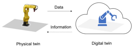
Figure 2.
Digital Twin: physical and virtual products. Adopted from [8].
According to Grevier and Vickers, the Digital Twin (DT) is “a set of virtual information constructs that fully describes a potential or actual physical manufactured product from the micro atomic level to the macro geometrical level”. Therefore, DT should supply any information that reflects that obtained from inspecting a physically manufactured product [7].
The Digital Twin implementation model [7,12], as shown in Figure 3, reflects the complexity of the design process that should be iterative and simultaneous at the same time.
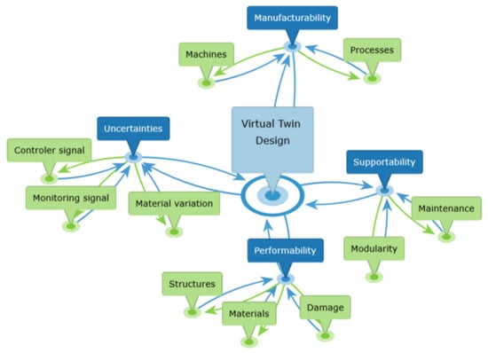
Figure 3.
Digital Twin implementation model. Adopted from [7,12].
There will be different types of Digital Twins depending on the phase of the system’s lifecycle [7,8]:
- Digital Twin Prototype (DTP)—the design version with all its variants. DTPs should exist for all manufactured products;
- The Digital Twin Instance (DTI) —the Digital Twin of each individually produced artefact. DTIs exist only for products where it is crucial to have information about that product throughout its life. DTs are operated on in a Digital Twin Environment (DTE);
- Digital Twin Aggregates (DTAs) —the aggregation or composite of all the DTIs.
The scope and meaning of the term Digital Twin evolved from the original concept, limited to air vehicles, through generic “product” to be extended on the virtual counterpart of production resources. According to Gartner, since 2016, Digital Twin technology has been one of the 10 Strategic Technology Trends (four times in a row). During 2016–2019 we observed DT’s evolving definition and usability characteristics from the business and technological perspective presented by Gartner (Table 1.)

Table 1.
Digital Twins as strategic technology trend from 2016–2019, by Gartner Inc.
3. Development of the Digital Twin Models
3.1. Open-Source Software Selections Approach
Searching for solutions enabling the creation of Digital Twin models using open-source software requires a review of available programs and programming libraries—including evaluation of applicability for the implementation of various functions required at the stage of creating and using the constructed models.
The presentation of open-source software enabling Digital Twinning is structured into three phases of the development process:
- Modelling;
- Visualising;
- Interconnecting.
As the concept of a Digital Twin is very general, the analytical part of the work initially focuses on modelling objects’ behaviour without considering the model’s visual representation. The analysis considers the compliance criterion of the analysed software with technologies used in the industry. It applies to standards for creating 3D models of objects, considering real-time requirements and compatibility with industrial communication standards. Then the visualisation methods that allow mirroring the actual appearance of objects with the use of 3D graphics are presented. Subsequently, the focus is on communication methods that interconnect the constructed models and real or simulated control systems. The tools for modelling PLC-based control systems and the creation of SCADA industrial processes visualisation are also presented. The final part shows examples of industrial equipment models built based on the described technologies.
3.2. Structure of Digital Twin
The Digital Twin concept covers various areas of life. However, the most significant emphasis is on introducing it into production systems. This is related to the complexity of such systems, their high cost, the necessity of training the operators, and minimising production costs. This results in the need to test such systems at the design stage to eliminate errors. Removing them from the finished installation could generate high costs and extend the project implementation time. It is also possible to train operators in advance on a virtual model, simulate emergencies, and minimise production costs by testing various control algorithms and management methods.
Depending on the needs, when creating a system with Digital Twin elements it is necessary to define the structure of such a system and select the elements to be simulated. In addition, it is also essential to define the accuracy of the representation of the subsystems of the real devices. An exemplary structure of such a system is shown in Figure 4.
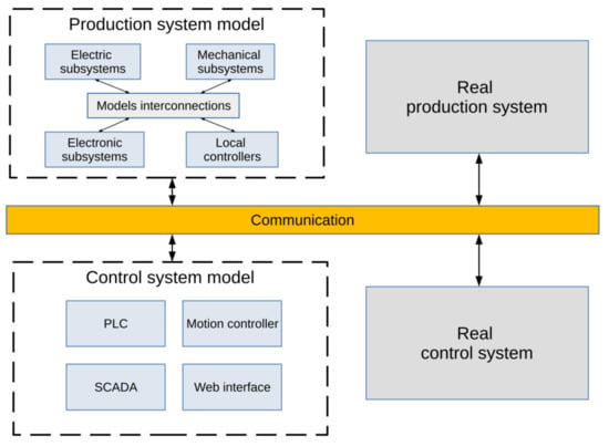
Figure 4.
Structure of the Digital Twin system. Source: own elaboration.
3.3. Physical Modelling
In the classic modelling approach based on the adopted physical model, a mathematical description of individual elements of the object is created. As a result, a model is built in the form of a system of differential equations which is then solved using numerical methods. Another approach is to create a block diagram based on equations that describe the signal flow between the input and output of the modelled system. Finally, the created block diagram is simulated using tools like MATLAB-Simulink, Scilab-Xcos. The disadvantage of this approach is that the connection structure of the block diagram does not correspond to the physical connections in the modelled system and there is a need to determine new equations whenever the structure of the system changes.
Physical modelling is another way to model systems. It has many advantages, the main one being the elimination of the stage of manual creation of the mathematical model of the system. This approach is used in specialised packages to simulate electronic circuits. In this type of system, the physical model of the system is created from the basic elements. Then, a mathematical model is automatically created for the created model, which is solved using numerical methods. Specialisation in one specific field, e.g., electronics appear to be the disadvantage of these programs in the open-source world. When designing systems following the Digital Twin concept, the usefulness of such programs is limited. Physical modelling of this type of system requires the use of universal software enabling interdisciplinary modelling. The Modelica modelling language [17] was developed to solve this problem. It allows an object-oriented description of the physical structure of the built model and all connections between its elements. Based on the description, mathematical equations describing the system are created automatically. This language is gradually becoming more and more popular among specialists creating complex system models.
The sample model showing the Electric Arc Furnace created using Modelica language is presented in Figure 5.
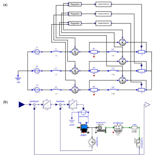
Figure 5.
Electric arc furnace model created using Modelica language: (a) high current circuit, (b) electrode control system. Source: [18].
3.4. Modelling of Multibody Mechanical Systems
Real mechanical systems consist of rigid or flexible bodies that perform translational and rotational movements. This kind of system is called a multibody system. Although the mechanical part is most often simulated when creating industrial object models within Digital Twins, this issue will be presented separately.
The kinematics of motion and their dynamics are often considered separately during modelling mechanical systems. In simpler models created, for example, for didactics, it is often enough to build a kinematic model showing the operation of the device without taking into account accelerations and forces. However, if the model is to be used for testing control systems, this approximation is often insufficient and dynamic phenomena must be considered.
Since creating models based on algebraic and differential equations takes a long time and is very complicated for complex models, physical modelling methods will be presented in the following section. Creating simulation models that include kinematics, dynamics, and collisions between objects should initially determine whether 3D graphics will be used to show the system’s operation or if only the values of the variables generated in the system are essential. Furthermore, it is crucial to define whether simulation software performs the visualisation or if an external library for 3D graphics will be employed.
Modelling of multibody systems can be realised using two groups of software:
- multibody simulation software;
- physical simulation libraries.
The advantage of universal multibody simulation software is using specialised text files or graphical representation to create a layout description. Models can be simulated through the use of classic programs or by using specialised simulation environments such as OpenModelica. Difficulties arise when there is a need to use external libraries for 3D visualisation. Additional work is needed to combine the developed multibody model with the 3D model developed for 3D visualisation. Examples of multibody simulation software are presented in Table 2.
Table 2.
Multibody simulation software.
An example of a multibody mechanical systems model created in Modelica language is presented in Figure 6. An example model of an industrial robot is part of the Modelica Standard Library. In part (a), a general diagram shows the connections between the control systems of individual axes and the mechanical arm system; part (b) shows the model of the mechanical arm system created with the multibody library.
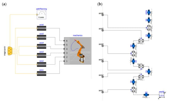
Figure 6.
Sample model of industrial robot created using Modelica language and multibody library (a) high-level diagram, (b) model of a robot arm. Source: Modelica Standard Library.
Another approach to modelling mechanical systems is to use physics engine libraries that simulate collision detection and soft and rigid body dynamics, which were developed mainly for the needs of games or physical simulations.
Applying libraries for physical simulations in modelling requires using library-native programming language to define the model in a text file format. Then, running the simulation requires creating a program and calling the function to load the model and simulate it. The advantage of libraries for physical simulations is the possibility of easy integration with external libraries for 3D visualisation. The most popular libraries are presented in Table 3.
Table 3.
Physics engine libraries.
3.5. Model Exchange and Co-Simulation
The Functional Mockup Interface (FMI) is an independent tool standard for exchanging dynamic models and co-simulation [26]. It is a free standard that defines a container and an interface to exchange dynamic models using a combination of XML files, binaries, and C code zipped into a single file [27]. FMI is the preferred model exchange and co-simulation format by nearly all modern simulation tools.
4. Digital Twin’s 3D Visualisation
An essential element of modern Digital Twins is 3D visualisation. Analysing the available solutions, they can be grouped into two sets:
- Libraries for 3D visualisation;
- Applications for 3D visualisation and simulation.
Libraries for 3D visualisation are a universal solution that allows building models of any complexity using classic programming languages. However, in the case of using these libraries in order to build a Digital Twin model, it is necessary to integrate them with libraries for physics modelling and communication. Examples of libraries for 3D visualisation are presented in Table 4.
Table 4.
Libraries for 3D visualisation.
Sample visualisation built with the OpenSceneGraph library is presented in Figure 7.
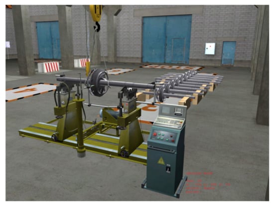
Figure 7.
Model shows an industrial device created by SRI of electronic educational resources using the OpenSceneGraph library. Source: [34].
Three-dimensional visualisation applications are more convenient in creating Digital Twins models, as they are an integrated solution that combines visualisation capabilities with physical engines. They also often have functionalities that allow for the interactive creation of models. However, the main problem with their use is the lack of built-in standard communication protocols. This forces the independent creation of modules, extending the capabilities of these libraries with communication and data exchange mechanisms. Table 5 describes the most appropriate software for visualisation and simulation.
Table 5.
Applications for 3D visualisation and simulation.
Gazebo is a simulation platform often used in robotics competitions; one of the more interesting events from the point of view of Digital Twins creators is the Agile Robotics for Industrial Automation Competition (ARIAC) [38]. The objective of the competition is to test the agility of industrial robot systems to enable industrial robots on the shop floors to be more productive, more autonomous, and more responsive to the needs of shop floor workers. A sample screen from the model created for the competition is presented in Figure 8.
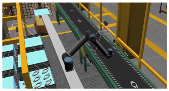
Figure 8.
Sample screen from the model created for the competition ARIAC by team River Lab. Source: [38].
5. Communication Methods
Modern industrial systems usually consist of multiple devices exchanging different types of data. Therefore, most modern control systems use open industrial communication protocols. However, it should be noted that being open does not always mean free and with public access. In the case of industrial protocols, it is usually a requirement to pay license fees and buy program implementations. In recent years, this situation has begun to change by spreading the idea of the Internet of Things and Industry 4.0 innovations. This accelerates the spread, also in industrial applications, of open, public, and multi-platform communication protocols [39,40]. An essential feature of these protocols is their complete openness and existence of software implementations distributed on an open-source basis. The most used open standards, for which open-source implementations are available, are presented in Table 6.
Table 6.
Industrial communication standards used in automation systems.
6. Control System Modelling
Creating complete Digital Twin models, in addition to the physical and visual parts, requires the reconstruction of a simplified or complete structure of the control system. The complexity of this task depends on the type of control system and the requirements to reproduce the signals in the communication interface.
When designing control systems for which it is required to develop the equivalent of a Digital Twin, it is imperative to properly select the structure and ensure the possibility of exchanging data with a Digital Twin. In a physical system, there are often many signals transmitted at high frequency; sometimes, there is an additional requirement related to the need to meet the requirements of real-time work. Developing full models of such real-time systems requires high computing power to meet computational complexity. For high-speed systems, computer simulations do not ensure synchronic data processing. Thus, specialised hardware accelerators using signal processors or FPGA matrices are usually employed. Creating such accurate models in Digital Twin systems is usually unnecessary, and simplified models with a high-level data exchange interface operating at relatively low frequencies are often sufficient.
In the case of modelling the control system, it is helpful to distinguish between the master control subsystem and the subsystem related to low-level control, as shown in Figure 7. The master control model can fully reflect the actual layout and should contain the same communication interfaces as the existing system. Then, a low-level control model can be a simplified model that reflects only the necessary functions for the master control model. Figure 9 shows a diagram of the relationship between the existing control system and its simplified model.
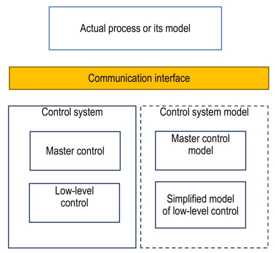
Figure 9.
The existing control system and its simplifying model. Source: own elaboration.
Creating a control model requires deciding the accuracy of reproducing the control algorithm and selecting a software solution to implement the algorithm. Depending on the decisions made, the software can be implemented as:
- a model using classical programming languages;
- a model developed using UML or SysML diagrams;
- a model developed in a simulation environment;
- program in a language compliant with IEC 61131;
- program following IEC 61499.
Analysing currently available software available under an open-source license proves that it is possible to create models of control systems using each of these solutions. Specialised tools that can be used to implement the control system model are presented in Table 7.
Table 7.
Control system modelling tools.
6.1. Modelling Using Classical Programming Languages
Modelling the control system using classic programming languages such as C, C++, Java, Python, JavaScript, etc., is a very flexible solution and practically free of restrictions in mapping the control algorithm. However, the disadvantage of this solution may be a tremendous amount of work resulting from the need to reproduce the control algorithm, which is often implemented using graphic languages following IEC 61131. On the other hand, many libraries allow data exchange in communication interfaces using Modbus TCP, OPC, OPC UA, Powerlink, and other protocols. In addition, in new control systems solutions, data exchange methods used in the Internet of Things solutions, such as MQTT, DDS/RTPS, ZeroMQ, etc., may gain popularity.
6.2. Modelling with UML or SysML Diagrams
If the control algorithm is described using state or sequential diagrams, it is possible to use tools that save the algorithm in UML or SysML diagrams [51,52,53]. For this type of method, choosing a tool that allows generating object code in one of the classic programming languages is necessary. Some difficulty may come from the integration of the generated code with communication libraries. An example of a simple program that allows graphically creating state diagrams and generating code in C, C++, and Python is CodeDesigner. This program is no longer actively developed, making it not the best solution for new projects. The actively developed software is the Eclipse IDE environment maintained by the Eclipse Foundation, which creates diagrams and generates code [54]. However, it requires a much more significant amount of work to master its functions. Some interesting tools for this kind of modelling are presented in Table 8.
Table 8.
Control system modelling tools.
6.3. Modelling in a Simulation Environment
An alternative to the presented solutions is to use simulation environments. They allow for creating a control system model using simplified programming languages or for creating a graphical representation of the control system in the form of a flowchart, considering dynamic elements such as the PID regulator. Table 9 presents the most popular programs of this type.
Table 9.
Simulation tools.
Scilab with the Xcos extension [55] is an open-source software for numerical computation. Xcos is a graphical editor to design hybrid dynamical system models. The built-in dynamic programming language allows the program to control algorithms effectively; the built-in case statement makes it easy to create programs that implement sequential control algorithms. In addition, it is possible to use libraries offering such communication methods as Modbus, DDE, and OPC for data exchange. It is also possible to build a control algorithm model in a graphical form in the Xcos module. However, connecting the model with the outside world will be problematic because the built-in libraries do not have communication functions.
A more effective alternative to the Scilab package is the OpenModelica environment, open-source software in the area of cyber-physical systems [17]. OpenModelica supports creating models of control algorithms in text form using the Modelica language or the built-in graphic editor. The control algorithm can be developed with a flowchart by applying the Modelica.Blocks library or in the form of a sequential diagram using the Modelica.StateGraph library (Figure 10).
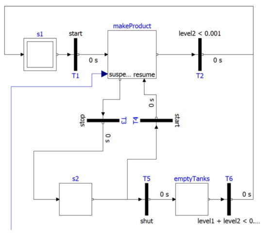
Figure 10.
Control system model in the OpenModelica environment with applying the Modelica.StateGraph library.
As an external library, Modelica DeviceDrivers is available under the BSD license to exchange data with the environment. This solution allows the keyboard, joystick, gamepad, and 3Dconnexion Spacemouse to interact with the model. It also allows data exchange using the shared memory mechanism or communication protocols UDP, TCP/IP, LCM, MQTT. All communication mechanisms can be implemented in the graphical environment. In addition, any simulation model built in an Open Modelica environment can be run independently of the environment and controlled using the OPC UA protocol.
6.4. Programming in a Language Compliant with IEC 61131
The core assets of highly automated production systems control codes for PLC and industrial robots. The Digital Twin concept can be applied to developing and maintaining these codes to deliver “pre-implementation” validation control projects and production management ideas. For example, suppose the control algorithm is available as a PLC program in one of the languages compliant with IEC 61131. Then, it is expandable to use solutions that allow for modelling the control system in languages compliant with the standard. In that case, it is possible to use an integrated development environment for machine automation Beremiz [56]. It implements open standards and is independent of the targeted device, and turns any processor into a PLC. An example of a PLC program developed with a graphical programming language, the sequential function chart (SFC) is shown in Figure 11.
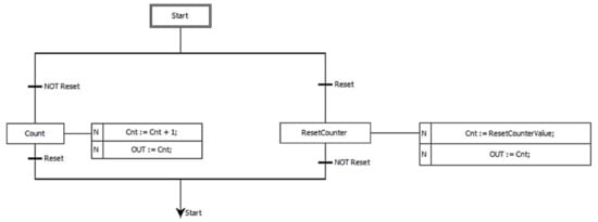
Figure 11.
Sample PLC program implemented with SFC graphic language in Bremiz environment.
Programs for PLC can be run using MatIEC software, an open-source compiler for the programming languages defined in the IEC 61131-3 standard. For data exchange, Modbus and OPC UA protocols are supported. It is also possible to create user interfaces that allow set variable values and visualise program states using the SVGHMI module. This module uses graphics in SVG format, which can be created and edited, for example, in the Inkscape environment [57].
6.5. Programming under IEC 61499
The last of these methods of creating a control system model uses software compatible with the IEC 61499 standard. The open-source representation of such software is the Eclipse 4diac™ package [58]. The 4diac environment enables programming distributed control systems using the methodology compliant with the IEC 61499 standard. The program is developed as a block diagram that implements a control algorithm assigned to different execution units. Block logic can be programmed using state diagrams or one of the languages included in the IEC 61131 standard. The general structure of the block is shown in Figure 12.
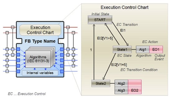
Figure 12.
Block structure according to IEC 61499.
For simulation, the 4diac FORTE runtime can be used as an execution unit, enabling the control algorithm to be run on a PC. In addition, the runtime allows for maintaining data exchange using various communication protocols like OPC UA, OPC DA, Modbus, MQTT, TCP, HTTP, ROS, Arrowhead, and openPOWERLINK.
7. Discussion
Digital Twinning is a significant and challenging strategic technological trend in the digital transformation of production systems. The design and operation of such systems are considered more effective when the idea of virtual mirroring, including modelling and concurrent simulation, are applied to the production environment. The concept of Digital Twin Shop floor (DTS) [3] can be representative for applying the Digital Twin concept to provide an effective way of achieving the physical-virtual convergence for the shop floor (Figure 13). The Digital Twin Shop floor consist of four components from [3]:
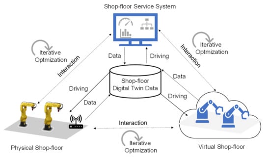
Figure 13.
A conceptual model of DTS. Adapted from [3].
- Physical Shop floor (PS)–organised physical assets and materials;
- Virtual Shop floor (VS)–a multidimensional digital model of PS;
- Shop-floor Service System (SSS)–enterprise information system (EIS), configured to meet the specific demands of PS and VS;
- Shop-floor Digital Twin Data (SDTD)–collects and stores data, aggregated data, fused data, algorithms, procedures, and product documentation.
Virtual shop floor evolves following physical shop-floor development, provides control orders for the physical shop floor, and optimises shop-floor service system strategies.
While PS and SSS are evolving with time, continuous interactions based on dynamic and real-time associations mapping and data/information/knowledge exchange make them consistent with each other and can be optimised iteratively. In addition, shop-floor Digital Twin data play a central role in integrating data flows through the Digital Twin shop floor in a heterogeneous environment of communications and data format standards. The STDT may be used for enterprise-wide purposes not limited to shop-floor management, such as supply chain management, applying the Logistics 4.0 concept. Implementation of the Digital Twin infrastructure presented above makes possible online process optimisation, as it is possible to study different strategies without having to stop and re-arm the production line. It also increases the possibilities of educating staff related to a given process by implementing various strategies and simulating emergencies in a simulated environment that behaves like a real system [4]. In [59], an example of implementing DT is presented to add manufacturing agility and resilience in the case of the additive manufacturing process through various models integration representing different approaches to predict, meet, and control key performance indices (KPI) of the manufacturing process.
A specific barrier to developing such systems is the current practice of using specialised commercial tools to create a virtual model and connect it to a real system using communication technologies. This approach is burdened with relatively high costs associated with the use of usually expensive commercial tools. Moreover, during the development process, some proprietary software solutions are used, which brings some difficulties in maintenance and apparent risks in case of dropping off updates by the supplier.
Currently, there is a vivid, emerging trend towards increasing the utilisation of open-source software in many industrial applications. There are many areas in which these solutions have become equivalent to commercial solutions, and in many cases, this type of software is more powerful and effective. The expected results are not limited to technical issues but also influence organisational culture and business models.
Based on the presented structured review of valuable software dedicated to various phases and tasks that should be realised while creating the whole Digital Twin system, it was demonstrated that the available open-source solutions cover all its aspects. Nevertheless, there are no available integrated open-source solutions that provide all the necessary functionalities accessible in a single suite for creating virtual models consistent with the concept of Digital Twins. To successfully create full-fledged models of Digital Twins and proceed with proposed open-source solutions, it is necessary to make additional efforts due to integration requirements. Therefore, it is advisable to increase the degree of integration of these tools, which will reduce the time needed to learn about these tools and the mechanisms that allow for their integration. As a result, the time required to develop Digital Twin models should also decrease. In return, the variety of available open-source tools makes it possible to create models that reflect all existing system elements.
As part of further work, we plan to undertake further activities related to constructing a uniform platform allowing for the creation of Digital Twin models, using open communication protocols for data exchange between all system elements. We also plan to develop modelling environments with specialised functions and libraries of elements facilitating the creation of such models.
8. Conclusions
The concept and the main goal of the article wase to present the most valuable and applicable open-source tools and communication technologies that may be employed to create models of production processes by applying the concept of Digital Twins. Whenever we mention commercial software, it is about the obvious general characteristics of it: ownership and cost of acquiring. However, the advantages of open-source solutions are not limited to financial and technical issues but also influence organisational culture and business models. Open-source software enables collaborative knowledge development, including the global context of users and developers, to support the quality and reliability of applications. Moreover, using open standards in automatics and communication preserve interoperability and durability. The maturity level of available open-source tools applicable for creating the building blocks of Digital Twins is sufficient for the effective implementation of complex applications. However, in terms of integrating these components, an increased workload is necessary compared to commercial solutions due to the heterogeneous nature of the development environment. It requires more flexible and innovative developers, not limited to industrial-specific knowledge silos based on the technology supplier ecosystem. Nevertheless, with some efforts to develop a more integrated solution, it is possible to effectively create Digital Twin models using open-source software.
Author Contributions
Conceptualisation, S.L. and R.K.; methodology, S.L. and R.K.; investigations, R.K., S.L., P.S. and A.T.; writing—original draft preparation, R.K. and S.L.; writing—review and editing, S.L.; visualisation, R.K. and S.L. All authors have read and agreed to the published version of the manuscript.
Funding
This research was funded by the Kielce University of Technology.
Institutional Review Board Statement
Not applicable.
Informed Consent Statement
Not applicable.
Data Availability Statement
Not applicable.
Conflicts of Interest
The authors declare no conflict of interest.
References
- Luściński, S.; Ivanov, V. A Simulation Study of Industry 4.0 Factories Based on the Ontology on Flexibility with Using FlexSim Software. Manag. Prod. Eng. Rev. 2020, 11, 74–83. [Google Scholar] [CrossRef]
- Hermann, M.; Pentek, T.; Otto, B. Design Principles for Industrie 4.0 Scenarios: A Literature Review; Working Paper; Technical University Dortmund: Dortmund, Germany, 2015. [Google Scholar] [CrossRef]
- Tao, F.; Zhang, M. Digital Twin Shop-Floor: A New Shop-Floor Paradigm Towards Smart Manufacturing. IEEE Access 2017, 5, 20418–20427. [Google Scholar] [CrossRef]
- Luściński, S. Digital Twinning for Smart Industry. In In Proceedings of the 3rd EAI International Conference on Management of Manufacturing Systems, Dubrovnik, Croatia, 6th–8th November 2018; 2018. [Google Scholar] [CrossRef] [Green Version]
- Open Source Lessons for 2021. Available online: https://cloudblogs.microsoft.com/opensource/2021/01/14/four-open-source-lessons/ (accessed on 20 November 2021).
- Grieves, M. Origins of the Digital Twin Concept. Working Paper. 2016. [Google Scholar] [CrossRef]
- Grieves, M.; Vickers, J. Digital Twin: Mitigating Unpredictable, Undesirable Emergent Behavior in Complex Systems. In Transdisciplinary Perspectives on Complex Systems. New Findings and Approaches; Kahlen, F.-J., Flumerfelt, S., Alves, A., Eds.; Springer International Publishing: Cham, Switzerland, 2017; pp. 85–114. ISBN 978-3-319-38754-3. [Google Scholar]
- Grieves, M. Virtually Intelligent Product Systems: Digital and Physical Twins. Complex Systems Engineering: Theory and Practice; American Institute of Aeronautics and Astronautics: Reston, VA, USA, 2019; pp. 175–200. ISBN 978-1-62410-564-7. [Google Scholar]
- Negri, E.; Fumagalli, L.; Macchi, M. A Review of the Roles of Digital Twin in CPS-Based Production Systems. Procedia Manuf. 2017, 11, 939–948. [Google Scholar] [CrossRef]
- Jones, D.; Snider, C.; Nassehi, A.; Yon, J.; Hicks, B. Characterising the Digital Twin: A Systematic Literature Review. CIRP J. Manuf. Sci. Technol. 2020, 29, 36–52. [Google Scholar] [CrossRef]
- Shafto, M.; Conroy, M.; Doyle, R.; Glaessgen, E.; Kemp, C.; LeMoigne, J.; Wang, L. DRAFT Modeling, Simulation, Information Technology and Processing Roadmap; National Aeronautics and Space Admnistration: Washington, DC, USA, 2010. Available online: https://www.nasa.gov/pdf/501321main_TA11-MSITP-DRAFT-Nov2010-A1.pdf (accessed on 15 November 2021).
- Stavropoulos, P.; Papacharalampopoulos, A.; Michail, C.K.; Chryssolouris, G. Robust Additive Manufacturing Performance through a Control Oriented Digital Twin. Metals 2021, 11, 708. [Google Scholar] [CrossRef]
- Gartner Identifies the Top 10 Strategic Technology Trends for 2017. Available online: https://www.gartner.com/en/newsroom/press-releases/2016-10-18-gartner-identifies-the-top-10-strategic-technology-trends-for-2017 (accessed on 15 November 2021).
- Gartner Identifies the Top 10 Strategic Technology Trends for 2018. Available online: https://www.gartner.com/en/newsroom/press-releases/2017-10-04-gartner-identifies-the-top-10-strategic-technology-trends-for-2018 (accessed on 15 November 2021).
- Top 10 Strategic Technology Trends for 2019. Available online: https://www.gartner.com/en/newsroom/press-releases/2018-10-15-gartner-identifies-the-top-10-strategic-technology-trends-for-2019 (accessed on 15 November 2021).
- Gartner Top 10 Strategic Technology Trends For 2019. Available online: https://www.gartner.com/smarterwithgartner/gartner-top-10-strategic-technology-trends-for-2019 (accessed on 15 November 2021).
- The Modelica Association—Modelica Association. Available online: https://modelica.org/index.html (accessed on 17 November 2021).
- Kazała, R. Modeling of Arc Furnace Circuit in Modelica Language. Zesz. Nauk. Politech. Łódzka 2009, 118, 135–142. [Google Scholar]
- MBDyn - MultiBody Dynamics - Homepage. Available online: https://www.mbdyn.org/ (accessed on 20 November 2021).
- FreeDyn. Available online: http://www.freedyn.at/ (accessed on 20 November 2021).
- Bullet Real-Time Physics Simulation | Home of Bullet and PyBullet: Physics Simulation for Games, Visual Effects, Robotics and Reinforcement Learning. Available online: https://pybullet.org/wordpress/ (accessed on 20 November 2021).
- Open Dynamics Engine. Available online: https://www.ode.org/ (accessed on 20 November 2021).
- PhysX SDK. Available online: https://developer.nvidia.com/physx-sdk (accessed on 20 November 2021).
- DART: Dynamic Animation and Robotics Toolkit. Available online: https://dartsim.github.io/ (accessed on 20 November 2021).
- SimTK: Simbody: Multibody Physics API: Project Home. Available online: https://simtk.org/projects/simbody/ (accessed on 20 November 2021).
- Blochwitz, T.; Otter, M.; Åkesson, J.; Arnold, M.; Clauss, C.; Elmqvist, H.; Friedrich, M.; Junghanns, A.; Mauss, J.; Neumerkel, D.; et al. Functional Mockup Interface 2.0: The Standard for Tool Independent Exchange of Simulation Models. Available online: https://ep.liu.se/en/conference-article.aspx?series=ecp&issue=76&Article_No=17 (accessed on 3 September 2012).
- Functional Mock-Up Interface. Available online: https://fmi-standard.org/ (accessed on 20 November 2021).
- Coin3D. Available online: https://coin3d.github.io/ (accessed on 20 November 2021).
- The OpenSceneGraph Project Website. Available online: http://www.openscenegraph.org/ (accessed on 20 November 2021).
- Panda3D | Open Source Framework for 3D Rendering & Games. Available online: https://www.panda3d.org/ (accessed on 20 November 2021).
- Three.Js JavaScript 3D Library. Available online: https://threejs.org/ (accessed on 23 November 2021).
- Babylon.Js: Powerful, Beautiful, Simple, Open-Web-Based 3D at Its Best. Available online: https://www.babylonjs.com (accessed on 23 November 2021).
- Index IModel.Js. Available online: https://www.itwinjs.org/v1/imodeljs.org (accessed on 23 November 2021).
- TSOGU. Available online: http://www.openscenegraph.org/index.php/gallery/use-cases/91-tsogu,%205.7.20120 (accessed on 23 November 2021).
- Webots: Robot Simulator. Available online: https://cyberbotics.com/ (accessed on 23 November 2021).
- Gazebo. Available online: http://gazebosim.org/ (accessed on 23 November 2021).
- FreeCAD: Your Own 3D Parametric Modeler. Available online: https://www.freecadweb.org/ (accessed on 23 November 2021).
- Agile Robotics for Industrial Automation Competition (ARIAC)|Challenge.Gov. Available online: https://www.challenge.gov/challenge/ariac-2021/ (accessed on 23 November 2021).
- Kazala, R.; Taneva, A.; Petrov, M.; Penkov, S. Wireless Network for Mobile Robot Applications. IFAC-Pap. 2015, 48, 231–236. [Google Scholar] [CrossRef]
- Kazala, R.; Strączyński, P.; Taneva, A.; Penkov, S. The Use of IoT Technologies for the Monitoring of Electrotechnological Systems. In Proceedings of the IEEE, Kielce, Poland, 31 December 2018. [Google Scholar]
- The Modbus Organization. Available online: https://modbus.org/ (accessed on 12 November 2021).
- Best Open Source Modbus Projects. Available online: https://www.findbestopensource.com/tagged/modbus (accessed on 12 November 2021).
- What Is OPC? Available online: https://opcfoundation.org/about/what-is-opc/ (accessed on 12 November 2021).
- Kazala, R.; Straczynski, P. The Most Important Open Technologies for Design of Cost Efficient Automation Systems. IFAC-Pap. 2019, 52, 391–396. [Google Scholar] [CrossRef]
- OPC Foundation. Available online: https://opcfoundation.org/ (accessed on 12 November 2021).
- Open62541: An Open Source Implementation of OPC UA. Available online: https://open62541.org/ (accessed on 12 November 2021).
- MQTT. The Standard for IoT Messaging. Available online: https://mqtt.org/ (accessed on 16 November 2021).
- About the DDS Interoperability Wire Protocol Specification Version 2.5. Available online: https://www.omg.org/spec/DDSI-RTPS/#documents (accessed on 16 November 2021).
- OpenDDS. Available online: https://opendds.org/ (accessed on 16 November 2021).
- Ethernet Powerlink. EPSG|Ethernet Powerlink. Available online: https://www.ethernet-powerlink.org/ (accessed on 16 November 2021).
- Axelsson, J. Unified Modeling of Real-Time Control Systems and Their Physical Environments Using UML. In Proceedings of the Eighth Annual IEEE International Conference and Workshop on the Engineering of Computer-Based Systems-ECBS 2001, Washington, DC, USA,, 17–20 April 2001; pp. 18–25. [Google Scholar] [CrossRef]
- Köhler, H.J.; Nickel, U.; Niere, J.; Zündorf, A. Integrating UML Diagrams for Production Control Systems. In Proceedings of the 22nd International Conference on Software Engineering, ICSE ’00, Limerick, Ireland, 9 June 2000; Association for Computing Machinery: New York, NY, USA, 2000; pp. 241–249. [Google Scholar]
- Thramboulidis, K.C. Using UML in Control and Automation: A Model Driven Approach. In Proceedings of the 2nd IEEE International Conference on Industrial Informatics, Berlin, Germany, 24–26 June 2004; pp. 587–593. [Google Scholar]
- Inc, E.F. The Community for Open Innovation and Collaboration|The Eclipse Foundation. Available online: https://www.eclipse.org/ (accessed on 17 November 2021).
- Home Page|Www.Scilab.Org. Available online: https://www.scilab.org/ (accessed on 17 November 2021).
- Home Page of Beremiz. Available online: https://beremiz.org/ (accessed on 17 November 2021).
- Draw Freely|Inkscape. Available online: https://inkscape.org/ (accessed on 17 November 2021).
- Eclipse 4diac. The Open Source Environment for Distributed Industrial Automation and Control Systems. Available online: https://www.eclipse.org/4diac/ (accessed on 17 November 2021).
- Papacharalampopoulos, A.; Michail, C.K.; Stavropoulos, P. Manufacturing Resilience and Agility through Processes Digital Twin: Design and Testing Applied in the LPBF Case. Procedia CIRP 2021, 103, 164–169. [Google Scholar] [CrossRef]
Publisher’s Note: MDPI stays neutral with regard to jurisdictional claims in published maps and institutional affiliations. |
© 2021 by the authors. Licensee MDPI, Basel, Switzerland. This article is an open access article distributed under the terms and conditions of the Creative Commons Attribution (CC BY) license (https://creativecommons.org/licenses/by/4.0/).