
Overview of Quartz Crystal Microbalance Behavior Analysis and Measurement


Abstract
:1. Introduction
2. Fundamental of QCM Sensor
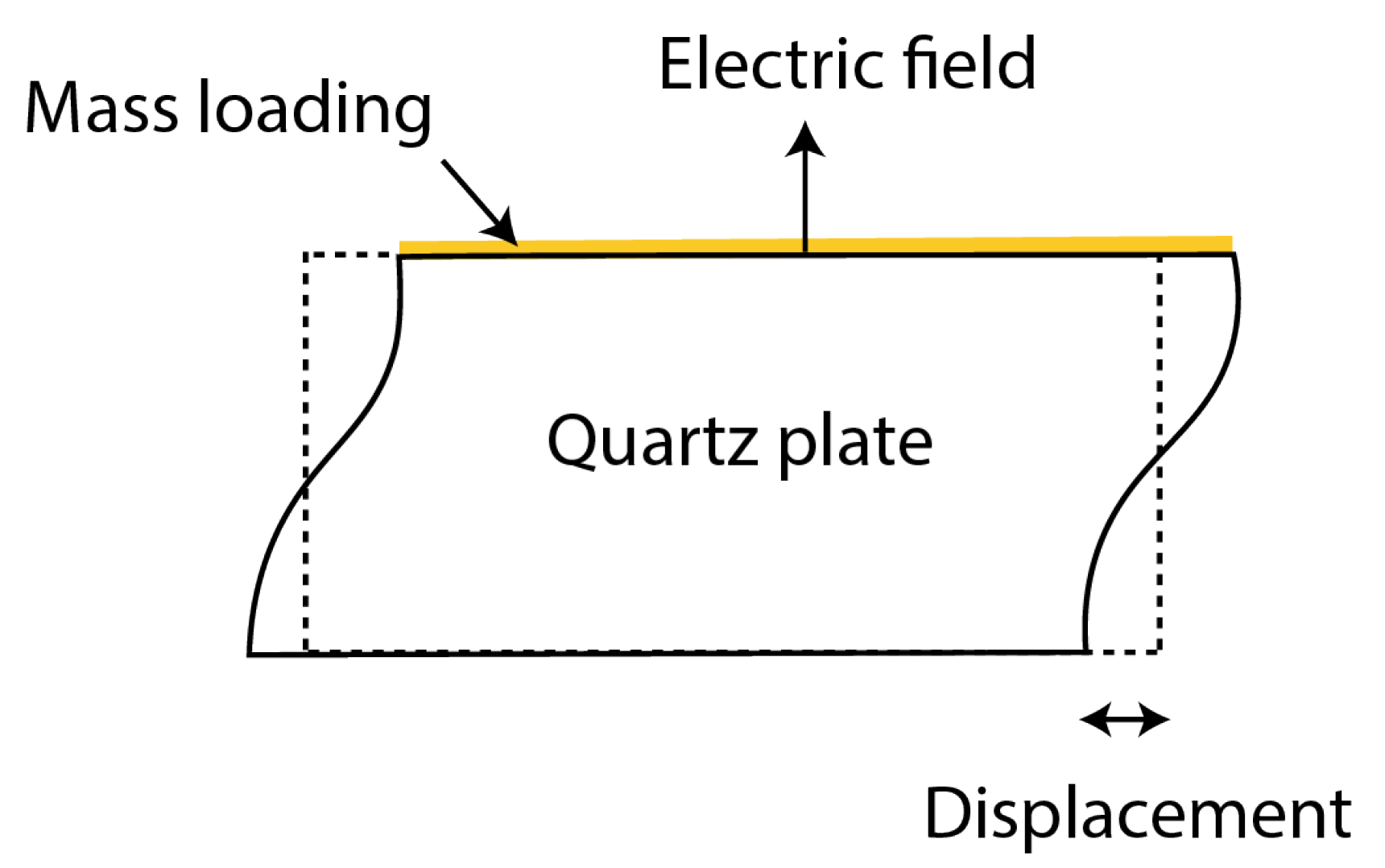
2.1. The Piezoelectric Effect
2.2. Physical Structure
2.3. Working Principle of QCM Sensor
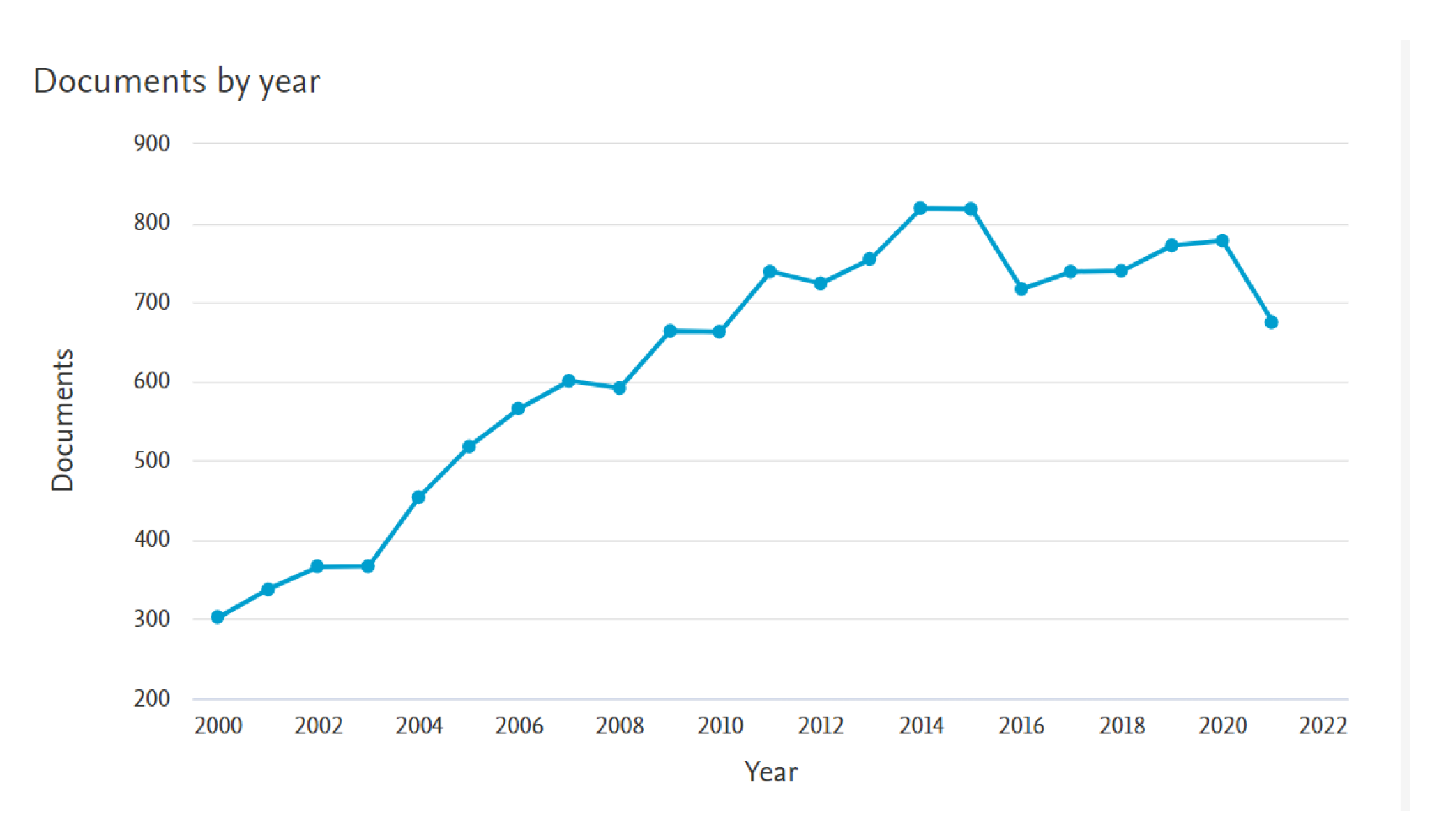
3. Survey of QCM Study
4. Theory of QCM
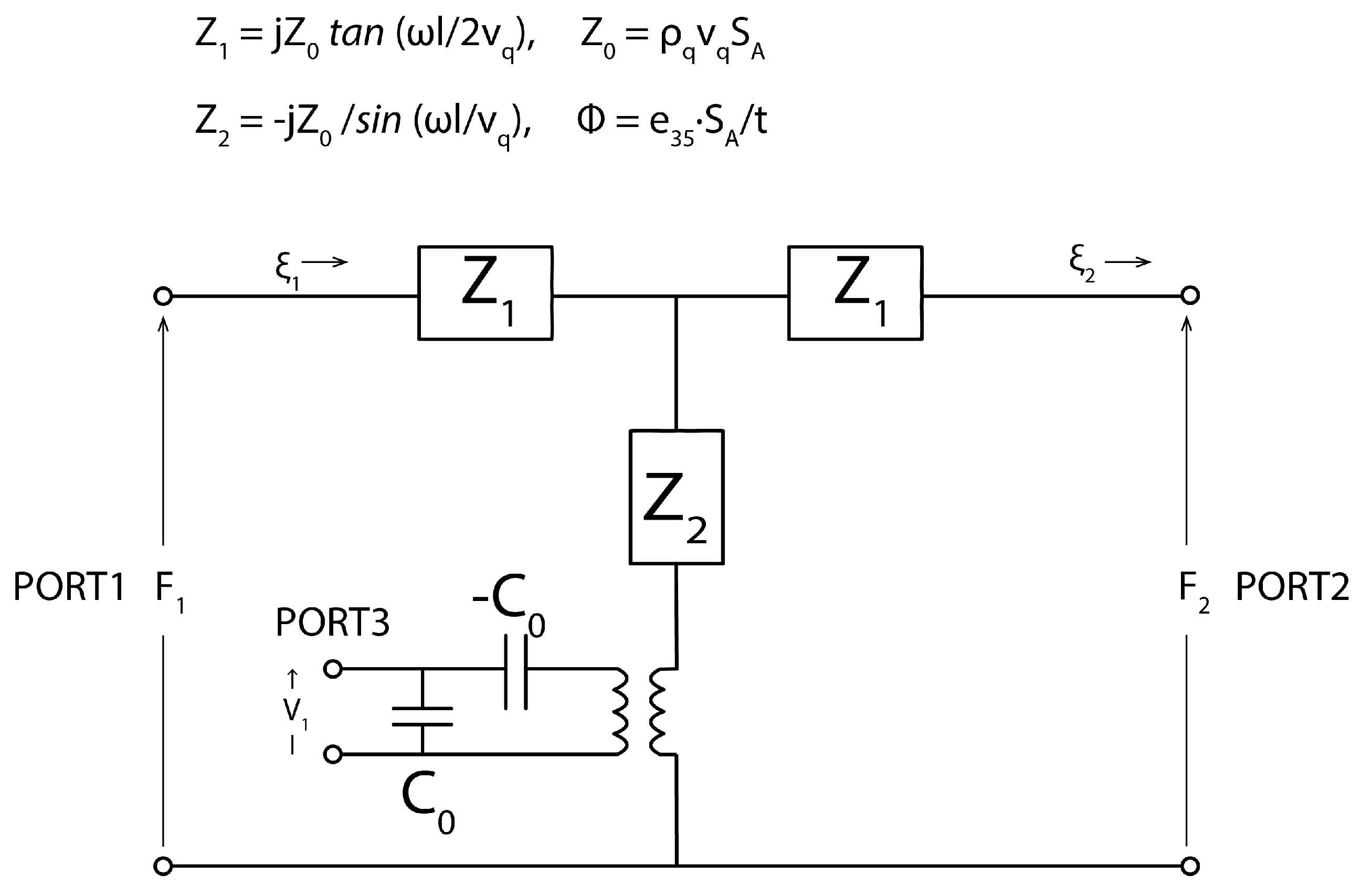
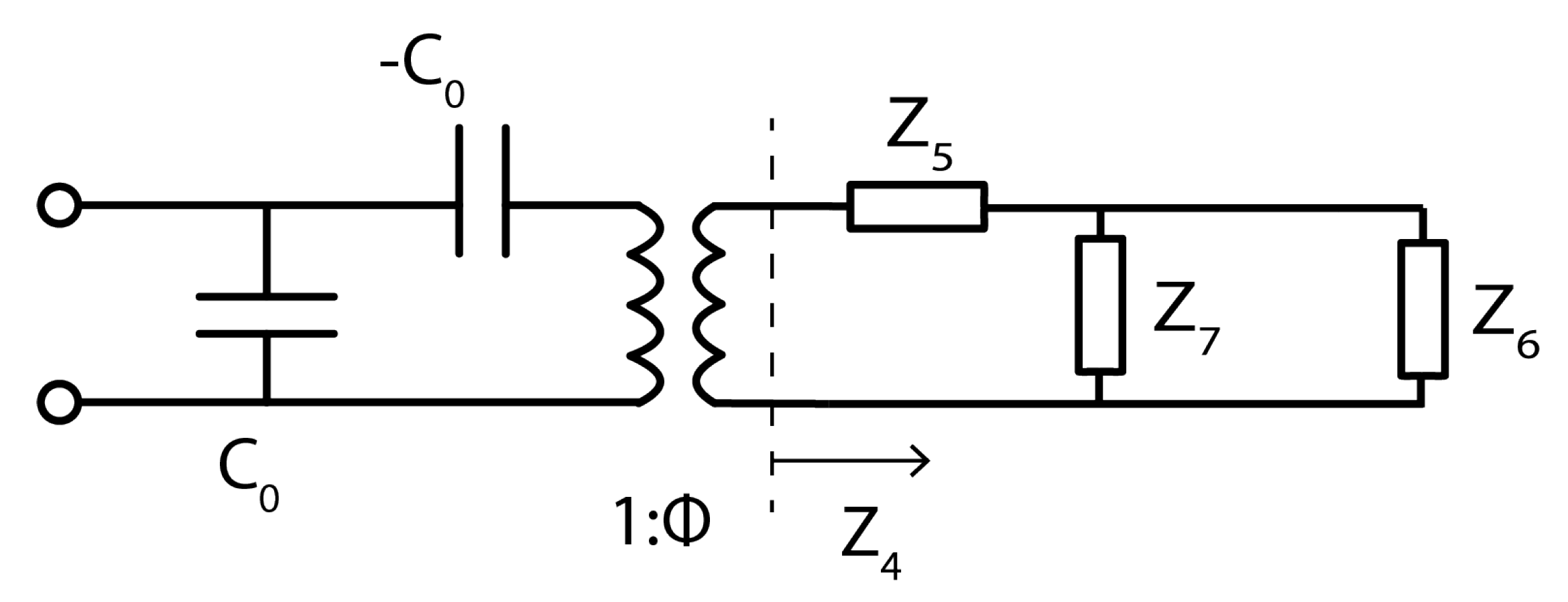
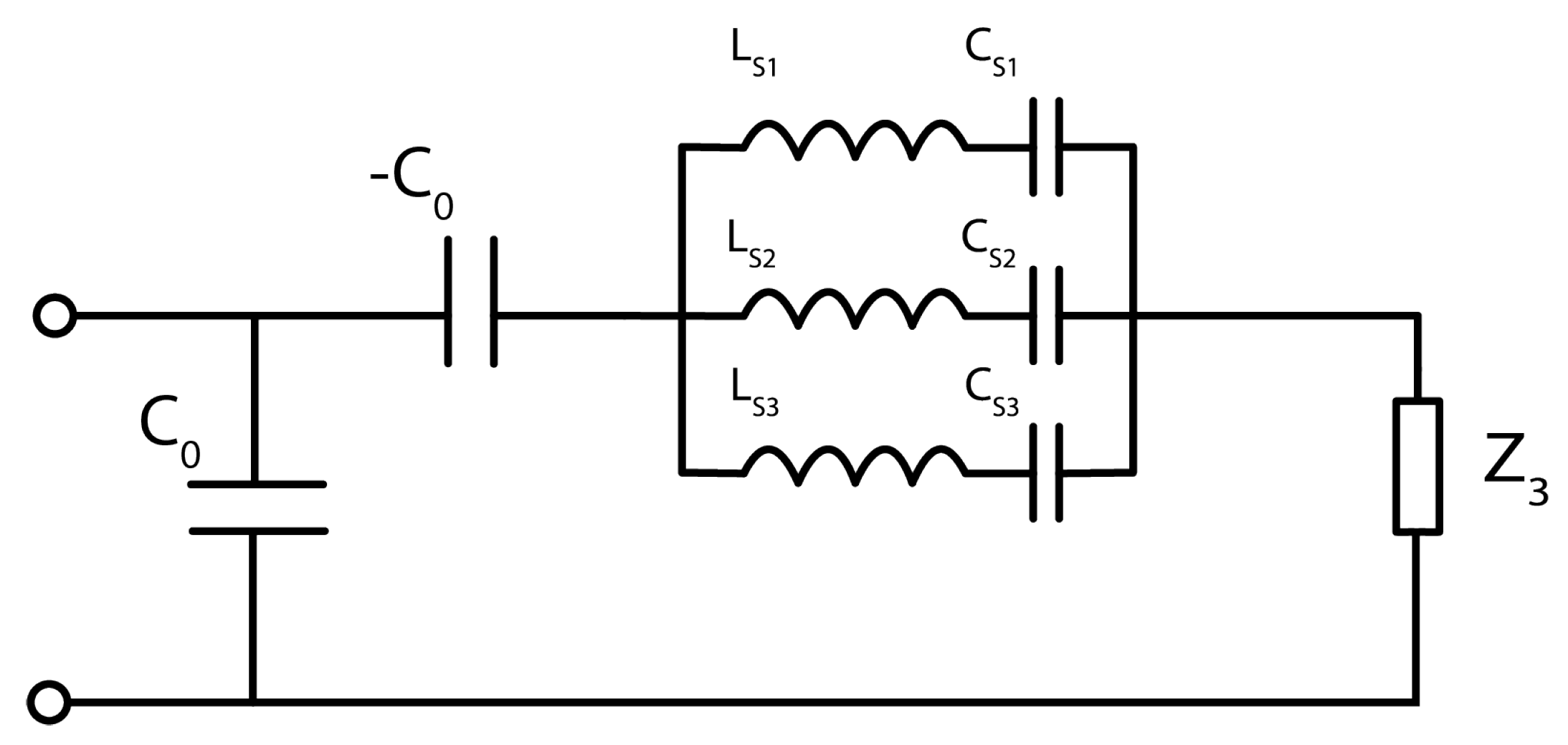
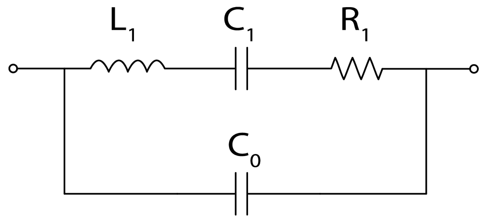
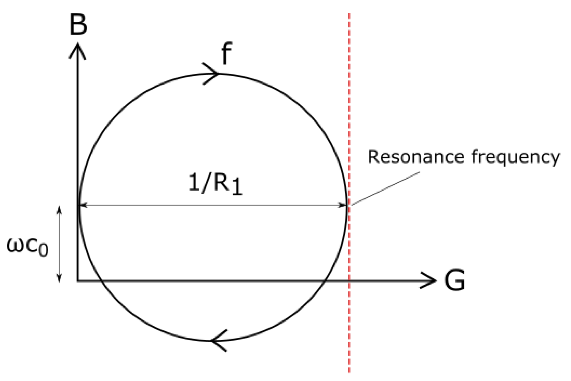
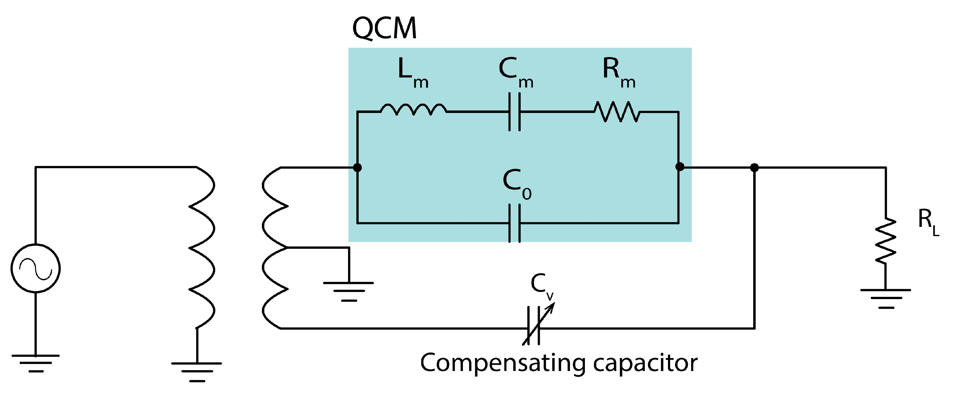
4.1. Equivalent Circuit
4.2. QCM Behavior
4.2.1. Gas Phase
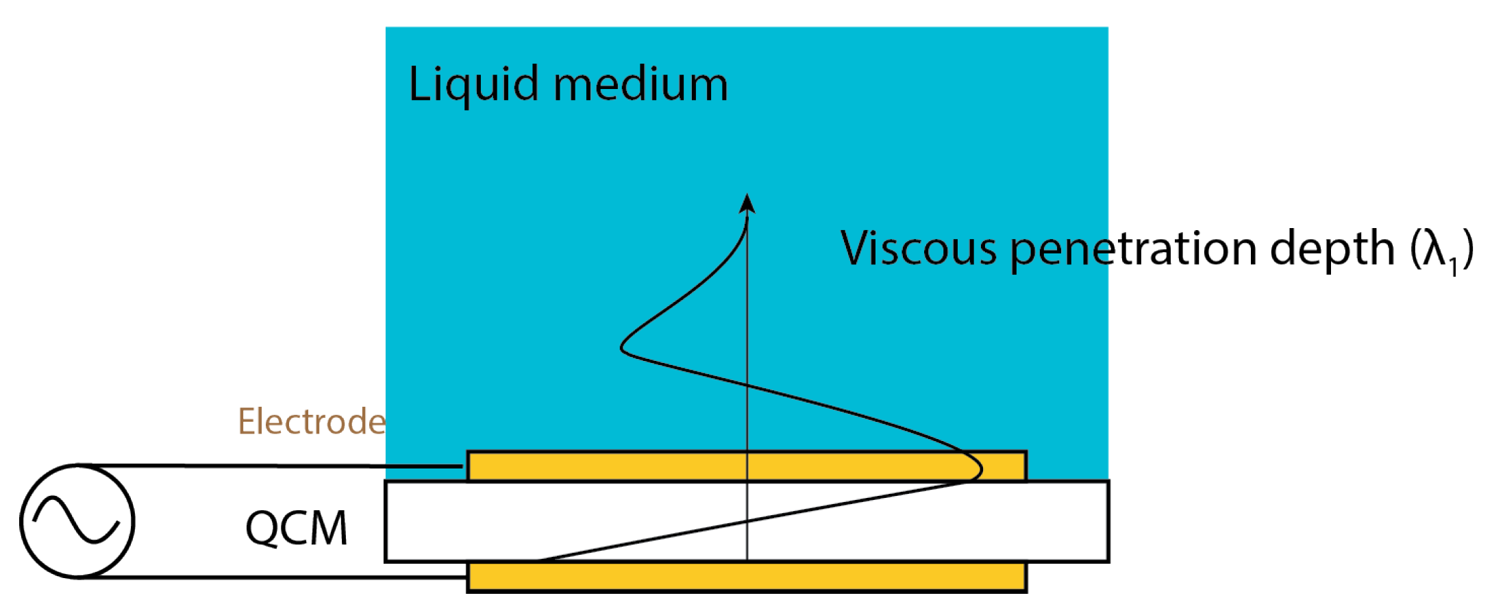
4.2.2. Liquid Phase
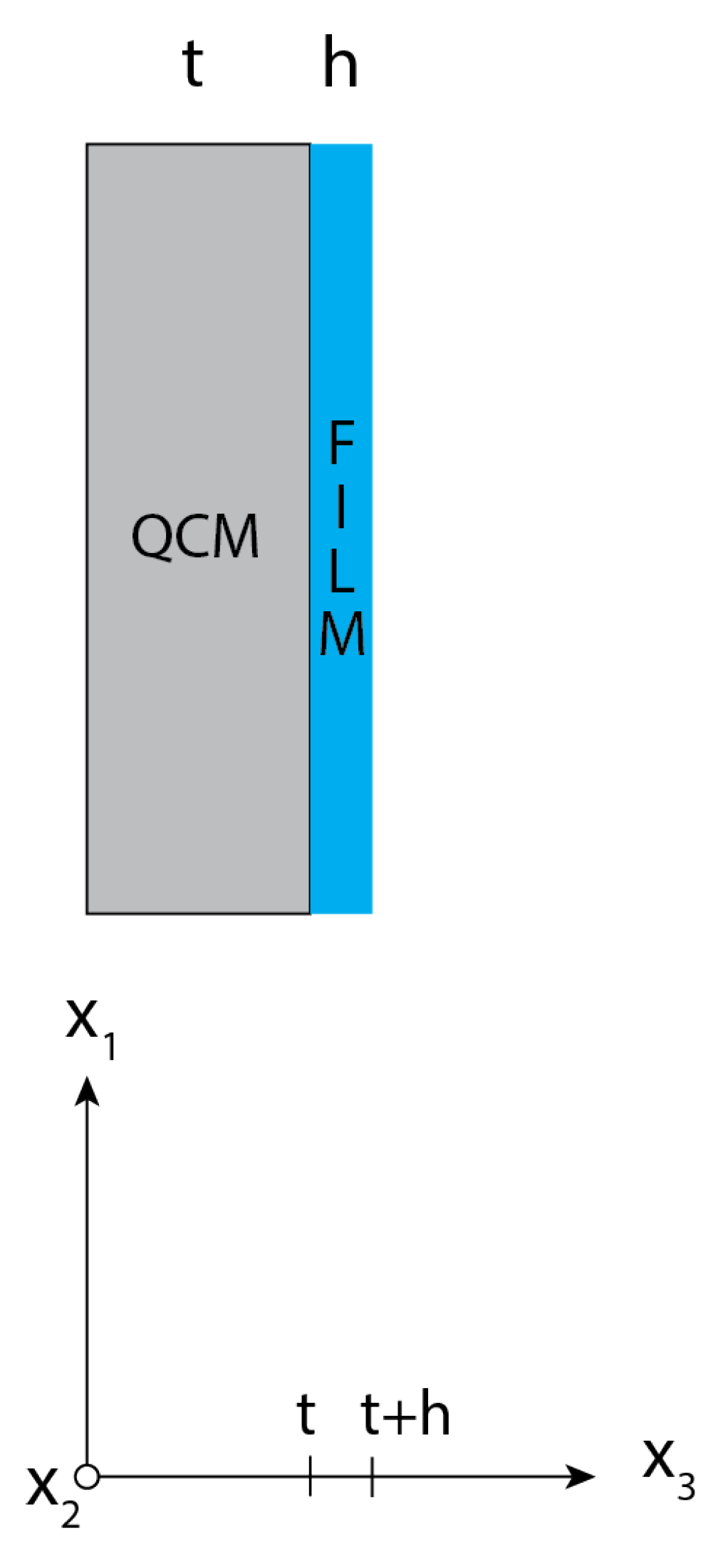
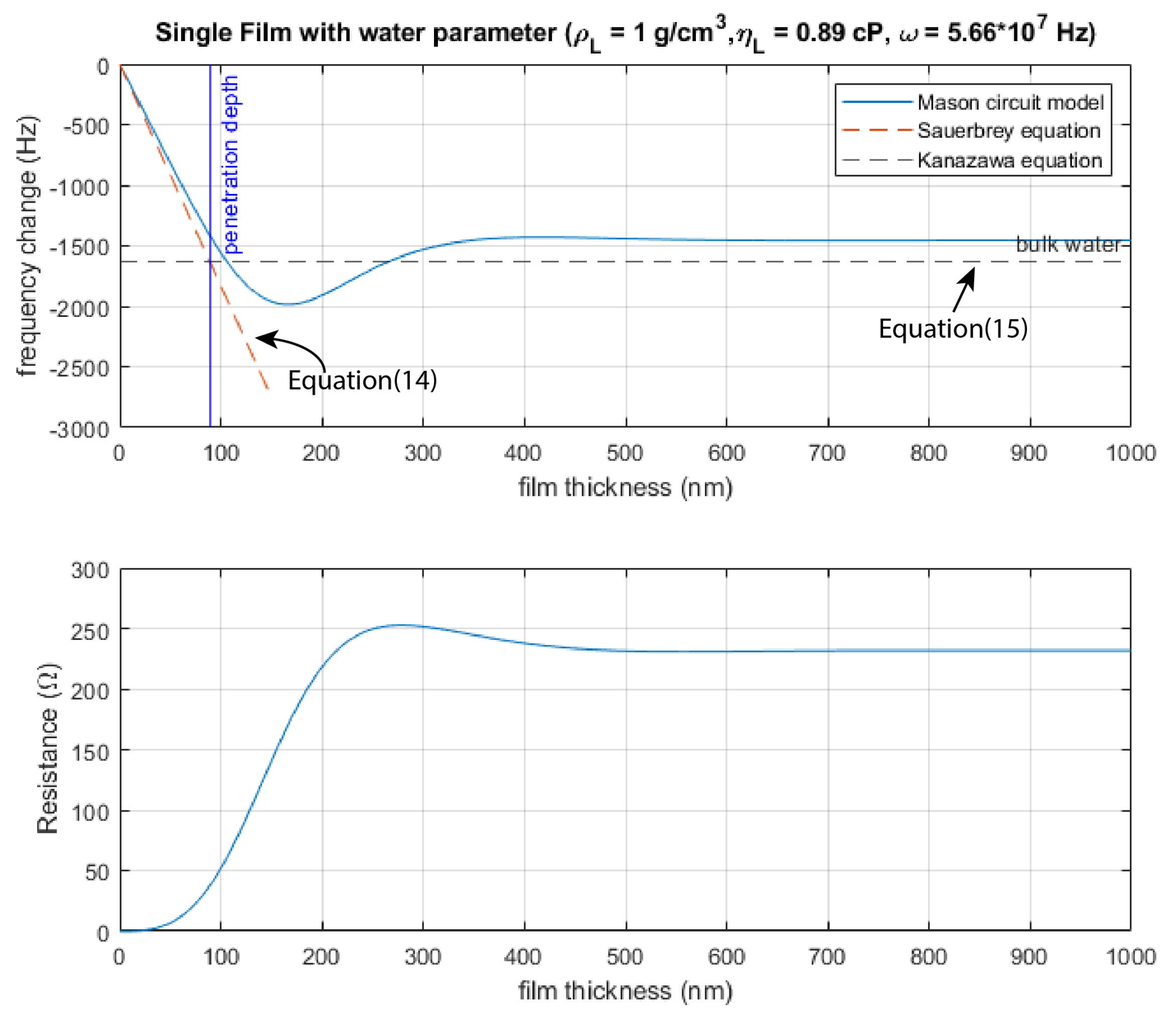
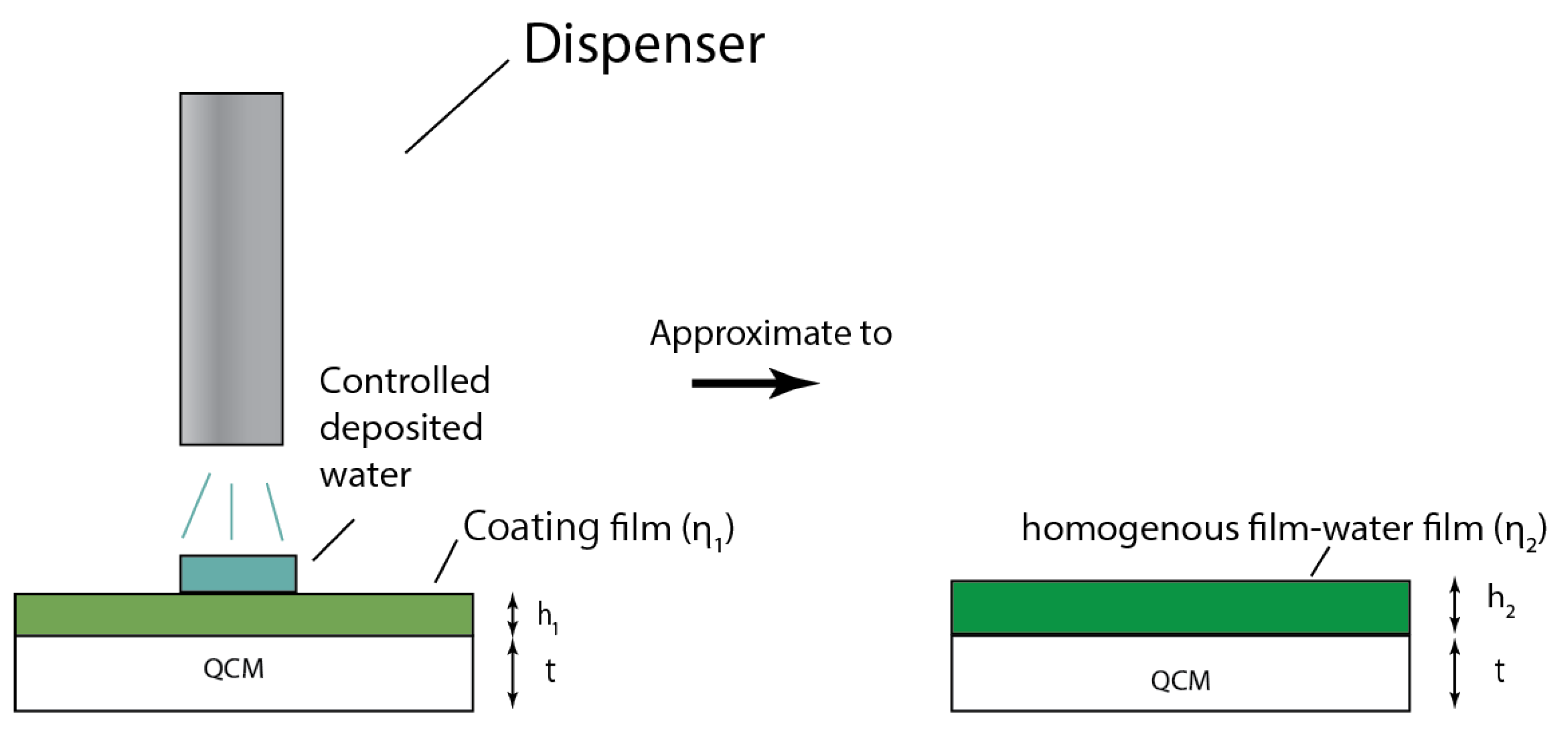
4.3. Film Behavior
5. QCM Measurement Methods
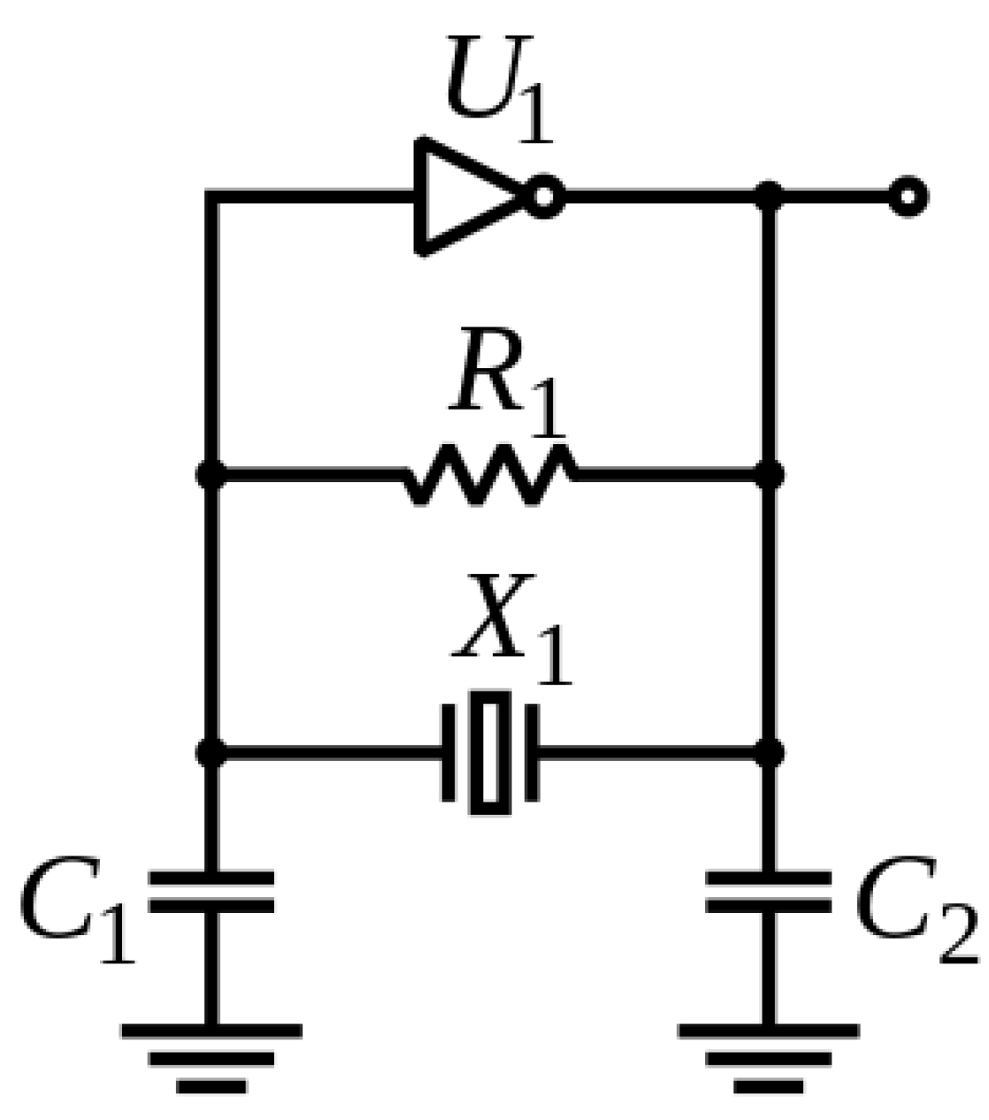
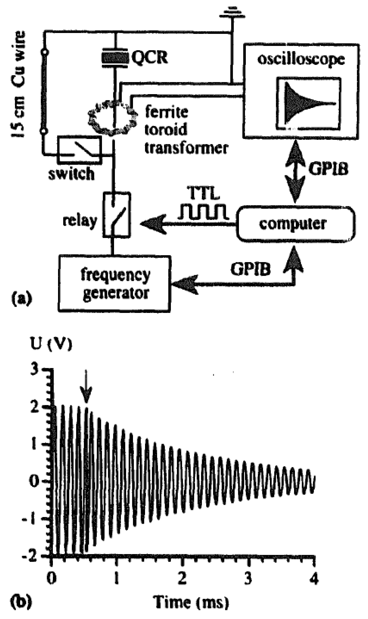
5.1. Oscillator Circuit
5.2. Dedicated Circuits
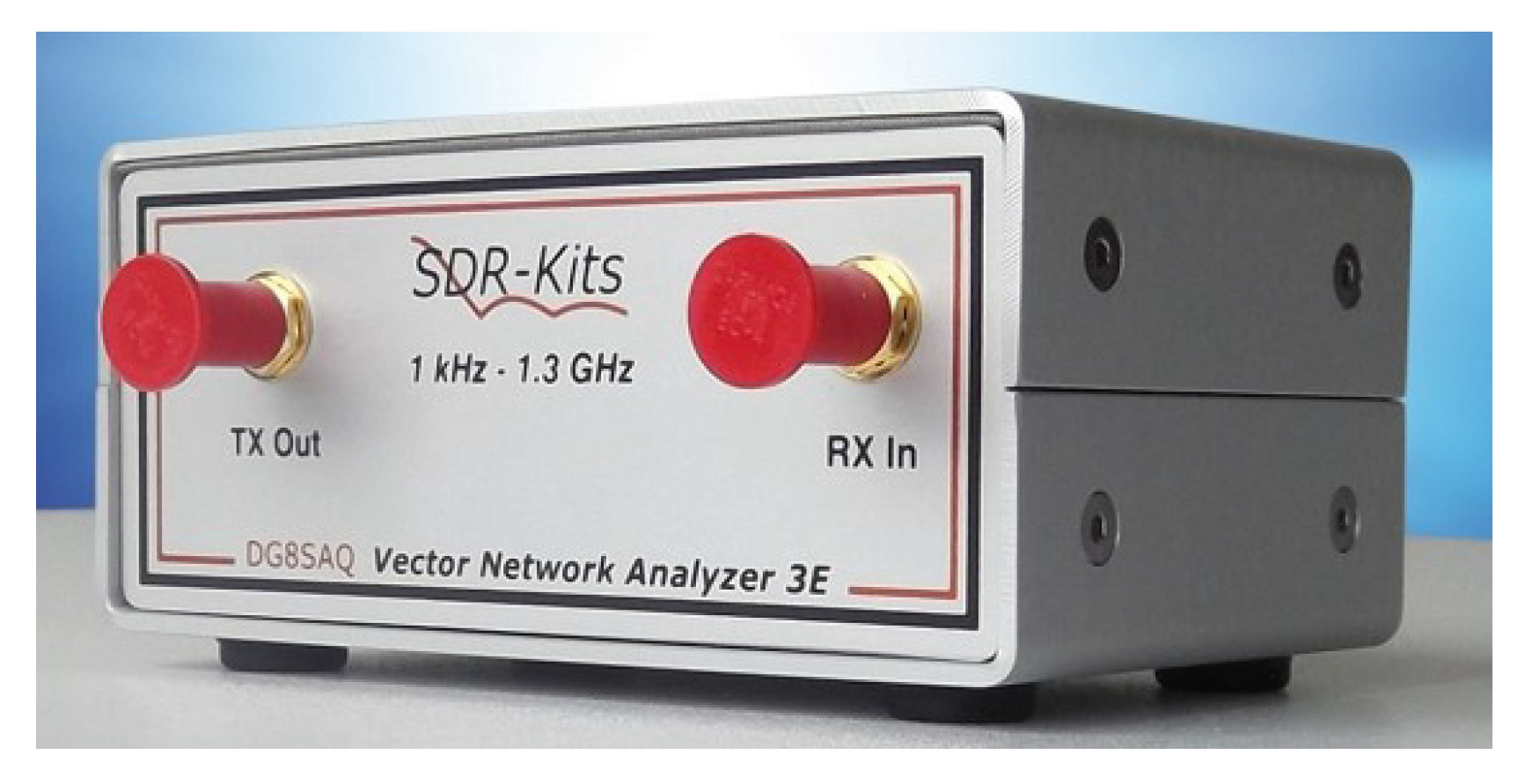
5.3. Vector Network Analyzer
6. Experiment on QCM with Viscous Loading
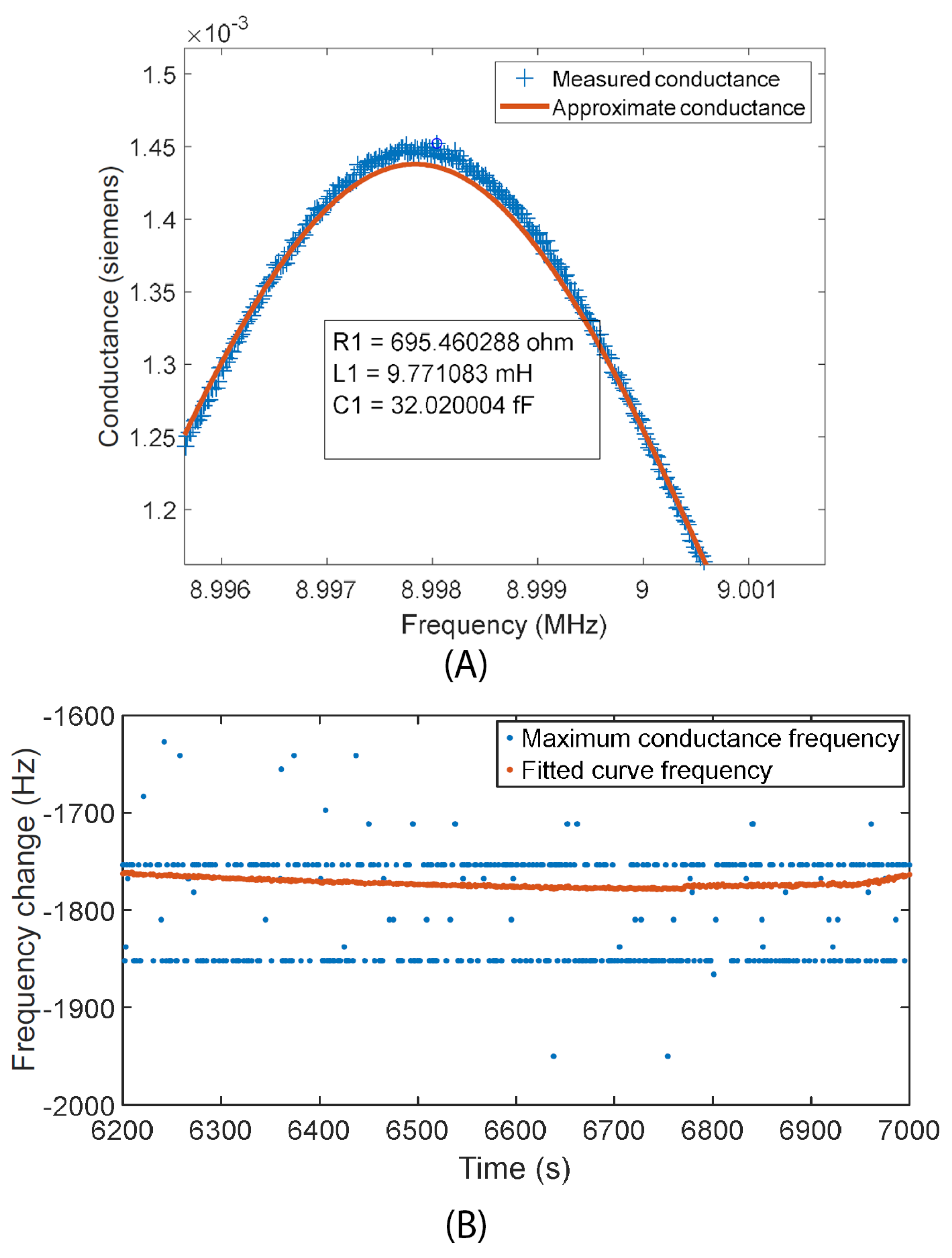
7. QCM Behavior Characterization
8. Conclusions
Author Contributions
Funding
Institutional Review Board Statement
Informed Consent Statement
Conflicts of Interest
Abbreviations
| QCM | Quartz Crystal Microbalance |
| PEG | Polyethylene Glycol |
| VNWA | Vector Network Analyzer |
References
- Oltra, R.; Efimov, I.O. Local sensitivity of an electrochemical quartz crystal microbalance: Spatial localization of the low frequency mode. Rev. Sci. Instrum. 1995, 66, 1136–1141. [Google Scholar] [CrossRef]
- Avramov, I.D. A 0-phase circuit for QCM-based measurements in highly viscous liquid environments. IEEE Sens. J. 2005, 5, 425–432. [Google Scholar] [CrossRef]
- Borngräber, R.; Schröder, J.; Lucklum, R.; Hauptmann, P. Is an oscillator-based measurement adequate in a liquid environment? IEEE Trans. Ultrason. Ferroelectr. Freq. Control 2002, 49, 1254–1259. [Google Scholar] [CrossRef] [PubMed]
- Nakamoto, T.; Kobayashi, T. Development of Circuit for Measuring Both Q Variation and Resonant Frequency Shift of Quartz Crystal Microbalance. IEEE Trans. Ultrason. Ferroelectr. Freq. Control 1994, 41, 806–811. [Google Scholar] [CrossRef] [PubMed]
- Sauerbrey, G. Verwendung von Schwingquarzen zur Wägung dünner Schichten und zur Mikrowägung. Z. Phys. 1959, 155, 206–222. [Google Scholar] [CrossRef]
- Thompson, M.; Arthur, C.L.; Dhaliwal, G.K. Liquid-Phase Piezoelectric and Acoustic Transmission Studies of Interfacial Immunochemistry. Anal. Chem. 1986, 58, 1206–1209. [Google Scholar] [CrossRef]
- Dybwad, G.L. A sensitive new method for the determination of adhesive bonding between a particle and a substrate. J. Appl. Phys. 1985, 58, 2789–2790. [Google Scholar] [CrossRef]
- Hayden, O.; Lieberzeit, P.A.; Blaas, D.; Dickert, F.L. Artificial antibodies for bioanalyte detection—Sensing viruses and proteins. Adv. Funct. Mater. 2006, 16, 1269–1278. [Google Scholar] [CrossRef]
- Latif, U.; Can, S.; Hayden, O.; Grillberger, P.; Dickert, F.L. Sauerbrey and anti-Sauerbrey behavioral studies in QCM sensors-Detection of bioanalytes. Sens. Actuators B Chem. 2013, 176, 825–830. [Google Scholar] [CrossRef]
- Noi, K.; Iwata, A.; Kato, F.; Ogi, H. Ultrahigh-frequency, wireless mems qcm biosensor for direct, label-free detection of biomarkers in a large amount of contaminants. Anal. Chem. 2019, 91, 9398–9402. [Google Scholar] [CrossRef]
- Kirkendall, C.R.; Kwon, J.W. Sub-picogram resolution mass sensing in a liquid environment using low-loss quartz crystal microbalance. In Proceedings of the IEEE Sensors, Waikoloa, HI, USA, 1–4 November 2010. [Google Scholar] [CrossRef]
- Huang, G.S.; Wang, M.T.; Su, C.W.; Chen, Y.S.; Hong, M.Y. Picogram detection of metal ions by melanin-sensitized piezoelectric sensor. Biosens. Bioelectron. 2007, 23, 319–325. [Google Scholar] [CrossRef] [PubMed]
- Shockley, W.; Curran, D.R.; Koneval, D.J. Trapped-Energy Modes in Quartz Filter Crystals. J. Acoust. Soc. Am. 1967, 41, 981–993. [Google Scholar] [CrossRef]
- Speller, N.C.; Siraj, N.; Regmi, B.P.; Marzoughi, H.; Neal, C.; Warner, I.M. Rational design of QCM-D virtual sensor arrays based on film thickness, viscoelasticity, and harmonics for vapor discrimination. Anal. Chem. 2015, 87, 5156–5166. [Google Scholar] [CrossRef] [PubMed]
- Speller, N.C.; Siraj, N.; McCarter, K.S.; Vaughan, S.; Warner, I.M. QCM virtual sensor array: Vapor identification and molecular weight approximation. Sens. Actuators B Chem. 2017, 246, 952–960. [Google Scholar] [CrossRef]
- Addabbo, T.; Bertocci, F.; Fort, A.; Mugnaini, M.; Shahin, L.; Vignoli, V.; Rocchia, S. A DDS-based multi-harmonic frequency meter for QCM sensor applications. Procedia Eng. 2014, 87, 288–291. [Google Scholar] [CrossRef]
- Pomorska, A.; Shchukin, D.; Hammond, R.; Cooper, M.A.; Grundmeier, G.; Johannsmann, D. Positive frequency shifts observed upon adsorbing micron-sized solid objects to a quartz crystal microbalance from the liquid phase. Anal. Chem. 2010, 82, 2237–2242. [Google Scholar] [CrossRef]
- Ward, M.D.; Delawski, E.J. Radial Mass Sensitivity of the Quartz Crystal Microbalance in Liquid Media. Anal. Chem. 1991, 63, 886–890. [Google Scholar] [CrossRef]
- Huang, X.; Bai, Q.; Hu, J.; Hou, D. A practical model of quartz crystal microbalance in actual applications. Sensors 2017, 17, 1785. [Google Scholar] [CrossRef] [Green Version]
- Milioni, D.; Mateos-Gil, P.; Papadakis, G.; Tsortos, A.; Sarlidou, O.; Gizeli, E. Acoustic Methodology for Selecting Highly Dissipative Probes for Ultrasensitive DNA Detection. Anal. Chem. 2020, 92, 8186–8193. [Google Scholar] [CrossRef]
- Kartal, F.; Çimen, D.; Bereli, N.; Denizli, A. Molecularly imprinted polymer based quartz crystal microbalance sensor for the clinical detection of insulin. Mater. Sci. Eng. C 2019, 97, 730–737. [Google Scholar] [CrossRef]
- Farka, Z.; Kovář, D.; Skládal, P. Rapid detection of microorganisms based on active and passive modes of QCM. Sensors 2015, 15, 79–92. [Google Scholar] [CrossRef] [Green Version]
- March, C.; García, J.V.; Sánchez, Á.; Arnau, A.; Jiménez, Y.; García, P.; Manclús, J.J.; Montoya, Á. High-frequency phase shift measurement greatly enhances the sensitivity of QCM immunosensors. Biosens. Bioelectron. 2015, 65, 1–8. [Google Scholar] [CrossRef]
- Schumacher, R.; Borges, G.; Kanazawa, K.K. The quartz microbalance: A sensitive tool to probe surface reconstructions on gold electrodes in liquid. Surf. Sci. 1985, 163, L621–L626. [Google Scholar] [CrossRef]
- Kitz, P.G.; Lacey, M.J.; Novák, P.; Berg, E.J. Operando EQCM-D with Simultaneous in Situ EIS: New Insights into Interphase Formation in Li Ion Batteries. Anal. Chem. 2019, 91, 2296–2303. [Google Scholar] [CrossRef] [PubMed]
- Acharya, B.; Sidheswaran, M.A.; Yungk, R.; Krim, J. Quartz crystal microbalance apparatus for study of viscous liquids at high temperatures. Rev. Sci. Instrum. 2017, 88, 025112. [Google Scholar] [CrossRef]
- Cao-Paz, A.M.; Rodríguez-Pardo, L.; Fariña, J.; Marcos-Acevedo, J. Resolution in QCM sensors for the viscosity and density of liquids: Application to lead acid batteries. Sensors 2012, 12, 10604–10620. [Google Scholar] [CrossRef] [PubMed]
- Abudu, A.; Goual, L. Adsorption of crude oil on surfaces using quartz crystal microbalance with dissipation (QCM-D) under flow conditions. Energy Fuels 2009, 23, 1237–1248. [Google Scholar] [CrossRef]
- Asai, N.; Shimizu, T.; Shingubara, S.; Ito, T. Fabrication of highly sensitive QCM sensor using AAO nanoholes and its application in biosensing. Sens. Actuators B Chem. 2018, 276, 534–539. [Google Scholar] [CrossRef]
- Song, W.; Guo, X.; Sun, W.; Yin, W.; He, P.; Yang, X.; Zhang, X. Target-triggering multiple-cycle signal amplification strategy for ultrasensitive detection of DNA based on QCM and SPR. Anal. Biochem. 2018, 553, 57–61. [Google Scholar] [CrossRef]
- Li, Q.; Gu, Y.; Jia, J. Classification of multiple chinese liquors by means of a QCM-based e-nose and MDS-SVM classifier. Sensors 2017, 17, 272. [Google Scholar] [CrossRef] [Green Version]
- Capuano, R.; Martinelli, E.; Ghezzi, S.; Paolesse, R.; Di Natale, C.; D’Amico, A.; Santonico, M.; Pennazza, G. An investigation about the origin of the lung cancer signalling VOCs in breath. In Proceedings of the IEEE Sensors, Valencia, Spain, 2–5 November 2014; Volume 2014. [Google Scholar]
- Saraoglu, H.M.; Selvi, A.O.; Ebeoglu, M.A.; Tasaltin, C. Electronic nose system based on quartz crystal microbalance sensor for blood glucose and hba1c levels from exhaled breath odor. IEEE Sens. J. 2013, 13, 4229–4235. [Google Scholar] [CrossRef]
- Khadka, R.; Aydemir, N.; Carraher, C.; Hamiaux, C.; Colbert, D.; Cheema, J.; Malmström, J.; Kralicek, A.; Travas-Sejdic, J. An ultrasensitive electrochemical impedance-based biosensor using insect odorant receptors to detect odorants. Biosens. Bioelectron. 2019, 126, 207–213. [Google Scholar] [CrossRef] [PubMed]
- Huellemeier, H.A.; Eren, N.M.; Ortega-Anaya, J.; Jimenez-Flores, R.; Heldman, D.R. Application of quartz crystal microbalance with dissipation (QCM-D) to study low-temperature adsorption and fouling of milk fractions on stainless steel. Chem. Eng. Sci. 2022, 247, 117004. [Google Scholar] [CrossRef]
- Tang, Y.; Tang, D.; Zhang, J.; Tang, D. Novel quartz crystal microbalance immunodetection of aflatoxin B1 coupling cargo-encapsulated liposome with indicator-triggered displacement assay. Anal. Chim. Acta 2018, 1031, 161–168. [Google Scholar] [CrossRef]
- Jayawardena, S.; Siriwardena, H.D.; Rajapakse, R.M.; Kubono, A.; Shimomura, M. Fabrication of a quartz crystal microbalance sensor based on graphene oxide/TiO2 composite for the detection of chemical vapors at room temperature. Appl. Surf. Sci. 2019, 493, 250–260. [Google Scholar] [CrossRef]
- Liu, L.; Fei, T.; Guan, X.; Zhao, H.; Zhang, T. Highly sensitive and chemically stable NH3 sensors based on an organic acid-sensitized cross-linked hydrogel for exhaled breath analysis. Biosens. Bioelectron. 2021, 191, 113459. [Google Scholar] [CrossRef]
- Zhang, D.; Chen, H.; Li, P.; Wang, D.; Yang, Z. Humidity Sensing Properties of Metal Organic Framework-Derived Hollow Ball-Like TiO2 Coated QCM Sensor. IEEE Sens. J. 2019, 19, 2909–2915. [Google Scholar] [CrossRef]
- Matsumoto, K.; Tiu, B.D.B.; Kawamura, A.; Advincula, R.C.; Miyata, T. QCM sensing of bisphenol A using molecularly imprinted hydrogel/conducting polymer matrix. Polym. J. 2016, 48, 525–532. [Google Scholar] [CrossRef]
- Nakamoto, T.; Moriizumi, T. A theory of a quartz crystal microbalance based upon a mason equivalent circuit. Jpn. J. Appl. Phys. 1990, 29, 963. [Google Scholar] [CrossRef]
- Mason, W.P. Electromechanical Transducers and Wave Filters; Van Nostrand: New York, NY, USA, 1942; p. 399. [Google Scholar]
- Granstaff, V.E.; Martin, S.J. Characterization of a thickness-shear mode quartz resonator with multiple nonpiezoelectric layers. J. Appl. Phys. 1994, 75, 1319–1329. [Google Scholar] [CrossRef] [Green Version]
- Lucklum, R.; Hauptmann, P. Δf-ΔR QCM technique: An approach to an advanced sensor signal interpretation. Electrochim. Acta 2000, 45, 3907–3916. [Google Scholar] [CrossRef]
- Nakamoto, T.; Suzuki, Y.; Moriizumi, T. Study of VHF-band QCM gas sensor. Sens. Actuators B Chem. 2002, 84, 98–105. [Google Scholar] [CrossRef]
- Lu, C.S.; Lewis, O. Investigation of film-thickness determination by oscillating quartz resonators with large mass load. J. Appl. Phys. 1972, 43, 4385–4390. [Google Scholar] [CrossRef]
- Hillier, A.C.; Ward, M.D. Scanning Electrochemical Mass Sensitivity Mapping of the Quartz Crystal Microbalance in Liquid Media. Anal. Chem. 1992, 64, 2539–2554. [Google Scholar] [CrossRef]
- Keiji Kanazawa, K.; Gordon, J.G. The oscillation frequency of a quartz resonator in contact with liquid. Anal. Chim. Acta 1985, 175, 99–105. [Google Scholar] [CrossRef]
- Cady, W.G. The piezo-electric resonator. Proc. Inst. Radio Eng. 1922, 10, 83–114. [Google Scholar] [CrossRef]
- Barnes, C. Development of quartz crystal oscillators for under-liquid sensing. Sens. Actuators A. Phys. 1991, 29, 59–69. [Google Scholar] [CrossRef]
- Satoh, T.; Ruslan, R.I.; Gotoh, S.; Akitsu, T. Double-resonance quartz crystal oscillator and excitation of a resonator immersed in liquid media. IEEE Trans. Ultrason. Ferroelectr. Freq. Control 2011, 58, 788–797. [Google Scholar] [CrossRef]
- Binti Ruslan, R.I.; Satoh, T.; Akitsu, T. Voltage-controlled double-resonance quartz oscillator using variable-capacitance diode. IEEE Trans. Ultrason. Ferroelectr. Freq. Control 2012, 59, 738–745. [Google Scholar] [CrossRef]
- Rodriguez-Pardo, L.; Fariña, J.; Gabrielli, C.; Perrot, H.; Brendel, R. Design considerations of miller oscillators for high-sensitivity QCM sensors in damping media. IEEE Trans. Ultrason. Ferroelectr. Freq. Control 2007, 54, 1965–1976. [Google Scholar] [CrossRef]
- Rodríguez-Pardo, L.; Rodríguez, J.F.; Gabrielli, C.; Perrot, H.; Brendel, R. TSM-AW sensors based on Miller XCOs for microgravimetric measurements in liquid media. IEEE Trans. Instrum. Meas. 2008, 57, 2309–2319. [Google Scholar] [CrossRef]
- Stanford Research Systems. QCM200 Digital Controller: Operation and ServiceManual; Stanford Research Systems, Inc.: Sunnyvale, CA, USA, 2018. [Google Scholar]
- Liu, N.; Han, J.; Liu, Z.; Qu, L.; Gao, Z. Rapid detection of endosulfan by a molecularly imprinted polymer microsphere modified quartz crystal microbalance. Anal. Methods 2013, 5, 4442–4447. [Google Scholar] [CrossRef]
- Muckley, E.S.; Lynch, J.; Kumar, R.; Sumpter, B.; Ivanov, I.N. PEDOT:PSS/QCM-based multimodal humidity and pressure sensor. Sens. Actuators B Chem. 2016, 236, 91–98. [Google Scholar] [CrossRef] [Green Version]
- Arnau, A. A review of interface electronic systems for AT-cut quartz crystal microbalance applications in liquids. Sensors 2008, 8, 370–411. [Google Scholar] [CrossRef] [Green Version]
- Beißner, S.; Thies, J.W.; Bechthold, C.; Kuhn, P.; Thürmann, B.; Dübel, S.; Dietzel, A. Low-cost, in-liquid measuring system using a novel compact oscillation circuit and quartz-crystal microbalances (QCMs) as a versatile biosensor platform. J. Sens. Sens. Syst. 2017, 6, 341–350. [Google Scholar] [CrossRef] [Green Version]
- Martin, S.J. Resonator/oscillator response to liquid loading. Anal. Chem. 1997, 69, 2050–2054. [Google Scholar] [CrossRef] [Green Version]
- Rodriguez-Pardo, L.; Cao-Paz, A.M.; Fariña, J. Design and characterization of an active bridge oscillator as a QCM sensor for the measurement of liquid properties and mass films in damping media. Sens. Actuators A Phys. 2018, 276, 144–154. [Google Scholar] [CrossRef]
- Rodahl, M.; Kasemo, B. Frequency and dissipation-factor responses to localized liquid deposits on a QCM electrode. Sens. Actuators B Chem. 1996, 37, 111–116. [Google Scholar] [CrossRef]
- Edvardsson, M.; Rodahl, M.; Kasemo, B.; Höök, F. A dual-frequency QCM-D setup operating at elevated oscillation amplitudes. Anal. Chem. 2005, 77, 4918–4926. [Google Scholar] [CrossRef]
- Hu, Z.; Hedley, J.; Keegan, N.; Spoors, J.; Gallacher, B.; McNeil, C. One-port electronic detection strategies for improving sensitivity in piezoelectric resonant sensor measurements. Sensors 2016, 16, 1781. [Google Scholar] [CrossRef] [PubMed] [Green Version]
- Jakoby, B.; Art, G.; Bastemeijer, J. Novel analog readout electronics for microacoustic thickness shear-mode sensors. IEEE Sens. J. 2005, 5, 1106–1111. [Google Scholar] [CrossRef]
- Nakamoto, T.; Nakamura, K.; Moriizumi, T. Study of oscillator-circuit behavior for QCM gas sensor. In Proceedings of the IEEE Ultrasonics Symposium, San Antonio, TX, USA, 3–6 November 1996; Volume 1. [Google Scholar] [CrossRef]
- Liu, G.; Dong, Z.; Li, D.; Wang, Y. Impedance measurement of quartz crystal based on network analysis method. In Proceedings of the Fourth International Seminar on Modern Cutting and Measurement Engineering, Beijing, China, 10–12 December 2010; Volume 7997. [Google Scholar] [CrossRef]
- Jenik, M.; Seifner, A.; Lieberzeit, P.; Dickert, F.L. Pollen-imprinted polyurethanes for QCM allergen sensors. Anal. Bioanal. Chem. 2009, 394, 523–528. [Google Scholar] [CrossRef] [PubMed]
- Minh, V.A.; Tuan, L.A.; Huy, T.Q.; Hung, V.N.; Quy, N.V. Enhanced NH 3 gas sensing properties of a QCM sensor by increasing the length of vertically orientated ZnO nanorods. Appl. Surf. Sci. 2013, 265, 458–464. [Google Scholar] [CrossRef]
- Yang, Y.; Zhang, W.; Guo, Z.; Zhang, Z.; Zhu, H.; Yan, R.; Zhou, L. Stability enhanced, repeatability improved Parylene-C passivated on QCM sensor for aPTT measurement. Biosens. Bioelectron. 2017, 98, 41–46. [Google Scholar] [CrossRef]
- Zainuddin, A.A.; Nordin, A.N.; Rahim, R.A.; Ralib, A.A.M.; Khan, S.; Guines, C.; Chatras, M.; Pothier, A. Verification of quartz crystal microbalance array using vector network analyzer and openQCM. Indones. J. Electr. Eng. Comput. Sci. 2018, 10, 84–93. [Google Scholar] [CrossRef]
- Mills, C.A.; Chai, K.T.; Milgrew, M.J.; Glidle, A.; Cooper, J.M.; Cumming, D.R. A multiplexed impedance analyzer for characterizing polymer-coated QCM sensor arrays. IEEE Sens. J. 2006, 6, 996–1002. [Google Scholar] [CrossRef] [Green Version]
- Wudy, F.; Multerer, M.; Stock, C.; Schmeer, G.; Gores, H.J. Rapid impedance scanning QCM for electrochemical applications based on miniaturized hardware and high-performance curve fitting. Electrochim. Acta 2008, 53, 6568–6574. [Google Scholar] [CrossRef]
- Aleixandre, M.; Nakamoto, T. Study of room temperature ionic liquids as gas sensing materials in quartz crystal microbalances. Sensors 2020, 20, 4026. [Google Scholar] [CrossRef]
- Songkhla, S.N.; Nakamoto, T. Signal Processing of Vector Network Analyzer Measurement for Quartz Crystal Microbalance with Viscous Damping. IEEE Sens. J. 2019, 19, 10386–10392. [Google Scholar] [CrossRef]
- Songkhla, S.N.; Nakamoto, T. Interpretation of quartz crystal microbalance behavior with viscous film using a mason equivalent circuit. Chemosensors 2021, 9, 9. [Google Scholar] [CrossRef]
- Voinova, M.V.; Jonson, M.; Kasemo, B. ’Missing mass’ effect in biosensor’s QCM applications. Biosens. Bioelectron. 2002, 17, 835–841. [Google Scholar] [CrossRef]
- Arnau, A.; Montagut, Y.; García, J.V.; Jiménez, Y. A different point of view on the sensitivity of quartz crystal microbalance sensors. Meas. Sci. Technol. 2009, 20, 124004. [Google Scholar] [CrossRef]
- Parlak, Z.; Biet, C.; Zauscher, S. Decoupling mass adsorption from fluid viscosity and density in quartz crystal microbalance measurements using normalized conductance modeling. Meas. Sci. Technol. 2013, 24, 085301. [Google Scholar] [CrossRef]
- Tan, F.; Qiu, D.Y.; Guo, L.P.; Ye, P.; Zeng, H.; Jiang, J.; Tang, Y.; Zhang, Y.C. Separate density and viscosity measurements of unknown liquid using quartz crystal microbalance. AIP Adv. 2016, 6, 095313. [Google Scholar] [CrossRef] [Green Version]
- Tarnapolsky, A.; Freger, V. Modeling QCM-D Response to Deposition and Attachment of Microparticles and Living Cells. Anal. Chem. 2018, 90, 13960–13968. [Google Scholar] [CrossRef]
- Dultsev, F.N.; Kolosovsky, E.A. QCM model as a system of two elastically bound weights. Sens. Actuators B Chem. 2017, 242, 965–968. [Google Scholar] [CrossRef]


| Title | Application | Coating Material | Analyte | Features | Ref. |
|---|---|---|---|---|---|
| Fabrication of highly sensitive QCM sensor using anodic aluminum oxide (AAO) nanoholes and its application in biosensing | Biosensing | mouse IgG | anti-mouse IgG | Increased QCM sensor sensitivity with the AAO nano well structure on the measuring an antigen-antibody interaction | [29] |
| Acoustic methodology for selecting highly dissipative probes for ultrasensitive DNA detection | Biosensing | Liposome/ DNA complex | DNA | Liposomes anchored to a dsDNA chain led to an improvement of the limit of detection (LoD) by 3 orders of magnitude when compared to direct DNA detection | [20] |
| Target-triggering multiple-cycle signal amplification strategy for ultrasensitive detection of DNA based on QCM and SPR | Biosensing | Streptavidin-coated AuNPs (gold nanoparticles) | DNA | A signal amplification process, including the exonuclease III and the hybridization chain reaction (HCR) of DNA. The reaction was detected by a QCM sensor together with SPR sensor. It exhibited a high sensitivity toward target DNA with a detection limit of 0.70 fM | [30] |
| Classification of multiple Chinese Liquors by Means of a QCM-based E-Nose and MDS-SVM Classifier | Electronic nose | PVC, Polyamide, Polyethlyene, Polytef, AgCl, Azithromycin, CuCl2 | Various Chinese liquors | Identify the different types of Chinese liquors using an array of QCM with an SVM classifier. The prediction accuracy (98.3%) showed superior performance of the MDS-SVM classifier over the back-propagation artificial neural network (BP-ANN) classifier (93.3%) and moving average-linear discriminant analysis (MA-LDA) classifier (87.6%) | [31] |
| An investigation about the origin of the lung cancer signaling VOCs in breath | Electronic nose | RuTPP, RhTPP, MnTPP, CoTPP, SnTPP, CoNO2TPP, CoOCH3TPP, MnOMC | Exhale breath sample from cancer patients | Partial Least Squares Discriminant Analysis (PLS-DA) has been used. The electronic nose could discriminate between cancer and non-cancer patients with more than 90% correct classification | [32] |
| Electronic nose system based on Quartz Crystal Microbalance sensor for blood glucose and hba1c levels from exhaled breath odor | Electronic nose | Zeolites, fullerene C60, chiral materials, polypyrrole, carbon graphites, ITO films, oligonucleotides | Exhale breath sample | The study of exhale gas to detect Blood Glucose and HbA1c level using a radial basis function neural network (RBFNN). The accuracies were 83.03% and 74.76% for HbA1c parameter predictions and glucose parameter prediction | [33] |
| An ultrasensitive electrochemical impedance-based biosensor using insect odorant receptors to detect odorants | Electronic nose | Odorant receptors (ORs): Or10a, Or22a, Or35a, Or71a | Methyl salicylate, E2-hexenal, 4-ethylguaiacol | OrX/Orco liposomes could sensitively and selectively detect their ligands by monitoring a change in frequency and dissipation signal of Quartz Crystal Microbalance | [34] |
| Application of Quartz Crystal Microbalance with dissipation (QCM-D) to study low-temperature adsorption and fouling of milk fractions on stainless steel | Food analysis | Stainless steel(SS2343) | Whole milk, skim milk, acid whey, acid permeate | acid whey (pH 4.6) demonstrated significant constant-rate adsorption at long processing times. It is anticipated that linear adsorption rates at extended times can be used to predict fouling propensity at a commercial scale | [35] |
| Novel Quartz Crystal Microbalance immunodetection of aflatoxin B1 coupling cargo-encapsulated liposome with indicator-triggered displacement assay | Food analysis | Glucose-loaded nanoliposome, labeled with monoclonal anti-AFB1 antibody | Aflatoxin B1 | QCM response showed a good linear relationship between the frequency shift, and AFB1 concentration could be obtained within the dynamic working range from 1.0 ng kg−1 to 10 mg kg−1 | [36] |
| Fabrication of a Quartz Crystal Microbalance sensor based on graphene oxide/TiO2 composite for the detection of chemical vapors at room temperature | Gas sensing | Graphene oxide (GO)/TiO2 | Ethanol vapor | The sensitivity of the composite functionalized QCM resonator for the EtOH vapor ranged from 8300 to 20 ppm | [37] |
| Highly sensitive and chemically stable NH3 sensors based on an organic acid-sensitized cross-linked hydrogel for exhaled breath analysis | Gas sensing | Acid-sensitized cross-linked poly(ethylene glycol) diacrylate (PEGDA) hydrogel | NH3 | CA (Citric Acid)/PEGDA and MA(Malic Acid)/PEGDA sensors exhibit a response as low as 0.05 ppm NH3 | [38] |
| Humidity Sensing Properties of Metal Organic Framework-Derived Hollow Ball-Like TiO2 Coated QCM Sensor | Humidity sensor | TiO2 Nanopowder | Humidity | The sensor indicates a large frequency change with an interaction that occurred between TiO2 and humidity molecules. The sensor exhibited a good repeatability when it was exposed to the moist air of 65% RH | [39] |
| Quartz crystal microbalance apparatus for the study of viscous liquids at high temperatures | Viscosity measurement | N/A | Liquid viscosity | The study of QCM in measuring high viscous oils at high-temperature range from 25 to 200 C | [26] |
| Resolution in QCM Sensors for the Viscosity and Density of Liquids: Application to Lead Acid Batteries | Viscosity measurement | N/A | Liquid viscosity | The application of liquid viscosity measurement in lead-acid battery. The findings show that the resolution limit only depends on the characteristics of the liquid to be studied and not on frequency | [27] |
| Operando EQCM-D with Simultaneous in situ EIS: New Insights into Interphase Formation in Li-Ion Batteries | EQCM | Super C65 Carbon, lithium iron phosphate (LiFePO4) | N/A | QCM with dissipation monitoring (EQCM-D) with simultaneous in situ electrochemical impedance spectroscopy (EIS) has been developed and applied to study the solid electrolyte interphase (SEI) formation on copper current collectors in Li-ion batteries | [25] |
| QCM sensing of bisphenol A using molecularly imprinted hydrogel/conducting polymer matrix | EQCM | Cyclodextrin-modified poly(L-lysine) (CD-PLL) | Bisphenol A (BPA) | The BPA-imprinted CD-PLL gel layer chip showed a greater Δf in response to BPA than the non-imprinted CD-PLL gel layer chip and the directly CD-immobilized chip | [40] |
| QCM Applications | Equations | Limitation |
|---|---|---|
| Thin film | Sauerbrey’s equation (Equation (18)) | For rigid film, it can be applied to several micrometers of film thickness. It is still applicable to viscous film if the film thickness is substantially less than the viscous penetration depth of that viscosity. |
| Bulk liquid | Kanazawa’s equation (Equation (19)) | Only applicable to non-newtonian bulk liquid. |
| Viscous film | Mason equivalent with the viscous film boundary condition (Equation (29)) | It can be applied to viscous film with its arbitrary thickness. |
| Measurement Methods | Advantages | Disadvantages |
|---|---|---|
| Oscillator circuit | Simple circuit design, only frequency counter is needed to measure oscillation frequency. | At high viscous loading, the circuit cannot maintain its positive feed back to continue oscillating. |
| Dedicated circuit | Additional parameter, i.e., resistance change, can be measured. Not the oscillation frequency but the resonant frequency is obtained. | Complicated design, need special knowledge to debug and fine-tune the system. |
| Vector Network Analyzer | Commercially available, sampling time and sweep frequency are adjustable. | Motional admittance method is not robust at highly viscous loading. Data curve fitting technique of the conductance curve help aids this drawback. |
| Film Materials | (Hz) | (Hz) | (Hz) | (Hz) | (Hz) | (Hz) |
|---|---|---|---|---|---|---|
| Glycerol | 900,4436 | 8,991,551 | −12886 | 19 | 740 | 721 |
| PEG20M | 900,1721 | 8,999,474 | −2246 | 15.92 | 18.28 | 2.36 |
| PEG2000 | 900,1739 | 8,999,439 | −2300 | 10.98 | 172.22 | 161.2 |
Publisher’s Note: MDPI stays neutral with regard to jurisdictional claims in published maps and institutional affiliations. |
© 2021 by the authors. Licensee MDPI, Basel, Switzerland. This article is an open access article distributed under the terms and conditions of the Creative Commons Attribution (CC BY) license (https://creativecommons.org/licenses/by/4.0/).
Share and Cite
Na Songkhla, S.; Nakamoto, T. Overview of Quartz Crystal Microbalance Behavior Analysis and Measurement. Chemosensors 2021, 9, 350. https://doi.org/10.3390/chemosensors9120350
Na Songkhla S, Nakamoto T. Overview of Quartz Crystal Microbalance Behavior Analysis and Measurement. Chemosensors. 2021; 9(12):350. https://doi.org/10.3390/chemosensors9120350
Chicago/Turabian StyleNa Songkhla, Sawit, and Takamichi Nakamoto. 2021. "Overview of Quartz Crystal Microbalance Behavior Analysis and Measurement" Chemosensors 9, no. 12: 350. https://doi.org/10.3390/chemosensors9120350
APA StyleNa Songkhla, S., & Nakamoto, T. (2021). Overview of Quartz Crystal Microbalance Behavior Analysis and Measurement. Chemosensors, 9(12), 350. https://doi.org/10.3390/chemosensors9120350