1. Introduction
A compound where two immiscible liquids are mixed so that one liquid is formed into small droplets is referred to as an emulsion [
1]. In addition to the described emulsions, there can also be multiple emulsions. In this case, an already existing emulsion is emulsified for a second time [
1].This emulsion is called a double emulsion, the most common types being water-in-oil-in-water (W
1/O/W
2) or oil-in-water-in-oil (O
1/W/O
2) emulsions [
2].
Double emulsions are mainly used in food, cosmetics, and pharmaceutical industries [
3]. Due to their characteristic structure, double emulsions are used to encapsulate value-giving ingredients, such as active ingredients in the pharmaceutical industry [
4] or vitamins in foods [
5]. As a result, they are protected from external influences during storage and can be released in a targeted manner as required [
6].
Conventional emulsification equipment, such as rotor-stator machines or high-pressure homogenizers, operate on the top-down principle [
7]. A two-stage process has been established for producing double emulsions. First, the inner emulsion is produced under high shear forces, resulting in very small droplets. In the second step, the double emulsion is produced using much lower shear forces. It is important that the acting forces are not too strong, otherwise the inner emulsion can be damaged and inner droplets can coalesce with the outer phase [
8]. However, this method does not allow for a precise adjustment of the droplet size [
7].
Microfluidic emulsification operates on the bottom-up principle. In this process, double emulsions are produced in small channels with little shear force in one- or two-stage processes. Due to the narrow channel geometries, microfluidic flow is laminar, resulting in an almost monodisperse droplet size distribution. In recent years, glass capillary devices for the production of double emulsions have been established, in which both droplet breakups take place in parallel [
9]. Both the sizes of the inner and outer droplets as well as the type and number of inner droplets can be precisely adjusted in the process [
10].
Regardless of the production method, all double emulsions can undergo different instability mechanisms [
2]. A fundamental differentiation must be made between reversible and irreversible instability mechanisms. Reversible mechanisms, such as creaming or sedimentation, do not permanently damage the double emulsion structure and can be undone by, e.g., shaking the product prior to use.
Irreversible instability mechanisms, however, cannot be reversed. These mechanisms involve diffusion between the inner and outer phases. Moreover, outer droplets can coalesce with each other, and inner droplets can coalesce with each other or with the outer phase.
In general, there are numerous measuring methods that can be used to monitor and analyze double emulsions during production and storage. One of the most important parameters for double emulsions is the droplet size, which determines the morphology and microstructure of double emulsions. Furthermore, changing droplet sizes indicate occurring instability mechanisms [
11]. Additionally, the encapsulation efficiency and rheological properties are of great importance [
8], and often change significantly with the change in droplet sizes over storage time. Typical measurement techniques known from single emulsion, however, often fail in double emulsions due to the emulsion-in-emulsion structure [
12] or the need for sophisticated sample preparation [
13].
Optical measuring methods can be used to make statements about the droplet size and filling degree; microscopy examinations play a particularly important role here. Among other things, it is the method of choice for confirming the multiple characteristics of a double emulsion [
14]. In addition, any changes in the double emulsion, such as the loss of internal water phase or changes in oil droplet size, can be qualitatively monitored over time.
To measure the droplet size distribution of emulsions, dynamic and static scattered light methods have been established as the most common laboratory methods. Here, the size of the inner water droplets is usually measured before the second emulsification step, which is otherwise not accessible with common measurement methods. Accordingly, after the second emulsification step, only the oil droplet size can be measured [
8].
The amount of inner water can be determined using a differential scanning calometry (DSC) analysis [
15]. Here, the double emulsion is strongly supercooled until the outer water phase freezes, followed by the inner water phase. The mass of inner water can be calculated from the heat released during the freezing. In addition, the supercooling required to freeze the inner water phase delivers information on the droplet size of the inner water phase. The smaller the droplet size, the deeper the necessary supercooling. However, there are some limitations to DSC measurements [
16].
NMR-based methods have also been proposed to determine both the amount of encapsulated water and inner droplet size in W/O/W emulsions [
17]. To date, they are limited to inner droplet sizes > 1 µm with a monodisperse droplet size distribution and the need to suppress any diffusion during the measurement period [
18].
Double emulsions are also characterized by rheological measurements. These are used to determine the filling degree of a double emulsion based on its viscosity. For this purpose, correlations such as the Krieger–Dougherty equation, which describes the viscosity as a function of the filling degree, are used. The higher the filling degree, the higher the viscosity of the double emulsion [
19].
The described methods for measuring the filling degree as well as the droplet size all share a common point in that they are usually performed offline. This requires sample preparation, and the sample is not suitable for further investigations after the measurement process. We therefore want to present a new optical measurement method based on the Raman effect. It can be performed both in- and online, so that the emulsion is not affected by the measurement.
The Raman effect is based on the interaction of molecules and electromagnetic radiation. When radiation hits a molecule, it is excited into a virtual state until the molecule is de-excited by emitting a photon. If the photon has the same energy as the exciting radiation, it is known as elastic Rayleigh radiation [
20].
However, for the Raman effect, the energy of the emitted photon is unequal to the exciting radiation, which is the reason why inelastic radiation is present here. The shift of the wavelength is called a Raman shift, and it is proportional to the energy difference between the incident and emitted light [
20].
In general, the Raman effect is a very weak effect, because compared with Rayleigh scattering, only one in every 10
8 photons show inelastic Raman scattering. Therefore, modern Raman spectrometers are equipped with an optical filter that separates the Rayleigh scattering from the Raman signal [
21].
The Raman intensity I
R can be calculated using the following correlation
where
I0 and
ν describe the intensity and frequency of the excitation laser, respectively,
N is the number of scattering molecules, α describes the polarizability, and
Q is the amplitude of the vibrational coordinate [
22].
Based on Equation (1), the strongest possible short wavelength laser will provide the strongest Raman signal. However, it should be noted that fluorescence excitation can also occur with short wavelength lasers, which produces a much stronger signal than the Raman signal [
22].
Raman spectrometers are used for most Raman measurements as they measure a complete spectrum of the sample, but are expensive to purchase. However, often only a small part of the spectrum is of interest. Therefore, there is the alternative of using photometers in combination with a dispersive element for detection [
23]. Photometers are not wavelength-selective and only detect the part of the spectrum that can pass through the dispersive elements. The speed and sensitivity are usually higher than with spectrometers, and the costs are significantly reduced.
For emulsions, Raman spectroscopy is used in monitoring emulsion polymerizations, usually in those using single emulsions [
24]. To the best of our knowledge, there are currently only two publications that address Raman spectroscopy measurements of double emulsions. First, coherent anti-Stokes Raman scattering microscopy was used to acquire an image of a double emulsion [
25]. Second, one of our previous papers dealt with the influence of refractive index matching in double emulsions on the Raman signal strength [
26].
This paper presents a new measurement method that combines Raman spectrometry and photometry to measure the filling degree and oil droplet size of individual W/O/W double emulsion droplets. The two measuring methods are combined in a way that they simultaneously operate without any time delay between the measurements.
2. Materials and Methods
2.1. Emulsion System and Experimental Setup
We dissolved 49% ammonium nitrate (CarlRoth, Karlsruhe, Germany) in the inner water phase, which served as a tracer for the Raman measurement. In addition, the ammonium nitrate aligns the refractive index of the inner water phase with that of the oil phase, which means that the inner water phase provides a stronger Raman signal [
26]. The oil phase was based on M10 silicone oil (CarlRoth, Karlsruhe, Germany), in which 2% Dowsil Resin XR 0497 (DowCorning, Midland, MI, USA) was dissolved as an emulsifier. In the outer water phase, 4% emulsifier was dissolved in the form of polyvinyl alcohol Kuraray Poval 26-80 (Kovayal, Hattersheim am Main, Germany).
The measurement system is capable of simultaneous spectroscopic and photometric Raman measurements. For the spectrometric measurements, the “RNX1-532” Raman spectrometer (Kaiser Optical Systems, Inc., Ann Arbor, MI, USA) was used. Three “CM 92N” custom photon multipliers (CPMs) (ProxiVision, Bensheim, Germany) were used for the photometric measurements. The “Kaiser NCO-0.5-VIS” backscatter probe, which is part of the spectrometer, was used for the measurements. The “gem532” laser (Novanta, Bedford, MA, USA) was used as excitation source. It emits a wavelength of 532 nm at a maximum power of 400 mW.
Figure 1 shows a scheme of the experimental setup. The detection signal was first passed through a long-pass filter after the Raman probe to block the laser wavelength. It was then split into four equally strong signals via a system of three 50:50 beam splitters (Thorlabs, Newton, NJ, USA). One signal was focused into an optical fiber, which was connected to the Raman spectrometer. The other three signals were each coupled into a CPM module. Because photometers are not wavelength-sensitive, bandpass filters were placed in front of the CPMs to isolate the signal from ammonium nitrate, silicone oil, and a reference. Details regarding the bandpass filters are listed in
Table A1 (
Appendix A).
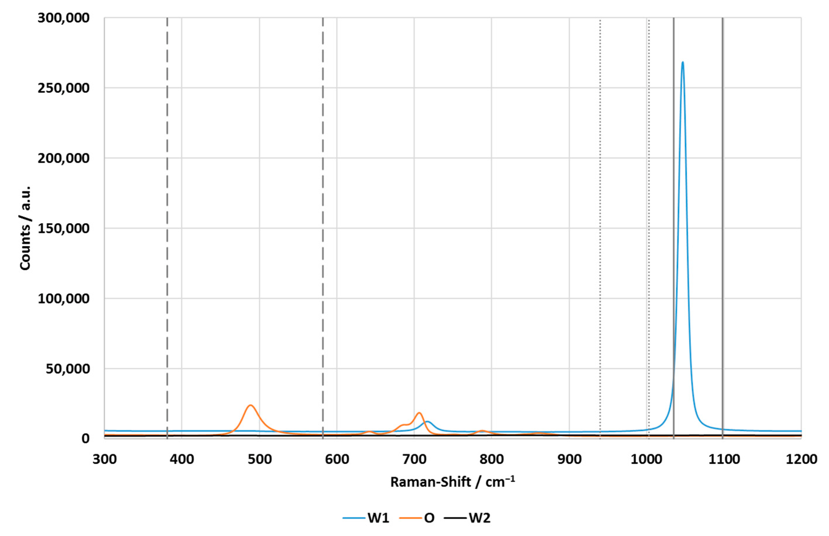
The limits of the optical filters are shown in
Figure 2. The filters for ammonium nitrate and the reference were located directly next to each other, while the filter for the oil phase was located separately.
The spectra of the individual phases were measured using the Kaiser spectrometer. For the measurements, a spectroscopy cuvette (Type: 100-10-40, Hellma Analytics, Müllheim, Germany) was used, which was placed in a cuvette holder belonging to the spectrometer. Due to this procedure, the spectra shown in
Figure 2 are quantitatively comparable.
Figure 2.
Spectra of the individually measured phases of the double emulsion. The spectra were measured using the Kaiser spectrometer at 1 s integration time and with five accumulations. The vertical lines visualize the limits of the oil phase filter (dashed lines), reference filter (dotted lines) and inner water phase filter (solid lines).
The spectra show that the outer water phase had no peaks in the relevant region of the spectrum. The inner water phase had a dominant peak due to ammonium nitrate at 1047 cm
−1, which was not overlapped by the oil phase. The oil phase was characterized by two peaks. The shorter wavelength peak at 489 cm
−1 was also not affected by the other phases, while the longer wavelength peak around 700 cm
−1 was overlapped by a small ammonium nitrate peak. However, this is not a concern, as the bandpass filter of the oil phase transmits light in the range of 381–582 cm
−1. The superposition is also irrelevant for the evaluation of the spectroscopic data, as the larger oil peak at 489 cm
−1 was used for this purpose.
Table 1 summarizes the measured Raman bands, including the respective excited molecular bond.
In principle, Raman spectroscopy is able to detect water bands and, therefore, directly measure water. For the measurement method presented in this article, this is not useful, as it is not possible to distinguish between the water signals of the inner and outer water phase.
2.2. Data Evaluation
The measured spectra were evaluated using a baseline correction. A base point is set in front of and behind the peaks, which form the start and end point of the baseline. First, the total integral between the selected boundaries is calculated. Then, the integral under the baseline is calculated and is subtracted from the total integral, resulting in the baseline-corrected integral of the peak. The boundaries are determined from the spectra of the double emulsions. For the oil phase, the boundaries are 400–600 cm−1, for the inner water phase, the boundaries are 1015–1065 cm−1.
The measurement of one filling degree took eight minutes. The spectrometer took four measurements at a speed of two minutes each during this time. For statistical evaluation, a spreadsheet software was used to calculate the mean value and standard deviation of the four measurements per filling degree.
Three photometric signals were measured: one for the inner water phase, oil phase, and as a reference, respectively. During the measurement time of eight minutes per filling degree, the CPMs were constantly measuring with an integration time of 2 ms. The number of counts measured over time is the output. Each peak in the photometric results corresponds to a double emulsion drop, which was individually evaluated.
An internally programmed Matlab software was used for the evaluation. The software read the data, calculated the integrals of the peaks, and subsequently, using the following equation
calculated the filling degree of each individual double emulsion droplet. In Equation (2), the three parameters are the calculated integrals of ammonium nitrate (
Int.
AN), silicone oil (
Int.
O), and the reference (
Int.
Ref). To obtain statistical information for the accuracy of the measurement, the mean value of the measured filling degrees of all double emulsion droplets, as well as the respective standard deviation, was calculated using a spreadsheet software.
The “Peak detection” function was used for the peak detection analysis. This outputs the position of the peak top as well as the position of the flanks at half-peak height. To find the position of the peak base before and behind the peak, the function has been edited. This allows the peak flank to be examined for an inflection point. To avoid setting a local minimum in the flank as the position of the peak base, a maximum Y-value for the peak base can be manually set in the user interface. This procedure was only carried out for the signal of the oil phase, as the largest peaks occurred here. The X-values of the peaks found here were utilized for the peak evaluation of the inner phase as well as the reference.
To determine the Y-value of the peak base, the mode of the baseline between two peaks was determined. Once the base points of the peak were found, a baseline was interpolated between them.
The measurement duration of a drop can be calculated from the X-positions of the peak. The volume flow in the capillary and its cross-sectional area were also known, so that the diameters of the droplets could be calculated using Equation (3)
where
dDrop describes the oil droplet diameter,
is the volume flow in of the capillary,
is its cross-sectional area, and
t describes the measurement duration of one oil droplet.
2.3. Emulsification
The double emulsion was produced in a two-stage process. First, an inner emulsion with a filling degree of 40% was produced using a “Megatron MT300” rotor-stator system (Kinematica AG, Malters) with a double-row ring gear. The rotational speed was set to 20,000 min−1, which corresponds to a peripheral speed of 27.2 m/s. The produced W1/O emulsion served as the stock emulsion for the other internal emulsions with lower filling degrees. To obtain the lower filling degrees, the corresponding quantities of oil phase and stock emulsion were mixed in laboratory bottles using stirred mixers.
The droplet size distribution of the stock emulsion cannot be measured using light scattering as a result of the similar refractive indices of the inner water phase and oil phase. Therefore, two further inner emulsions were produced: one with 40% ammonium nitrate in the inner water phase and the other with 60% ammonium nitrate. The oil phase was not changed. The filling degree of both emulsions was 40%, and the emulsification procedure was the same as for the stock emulsion. Both emulsions were measured by static laser light scattering using a HORIBA LA-950 particle analyzer (Microtrac Retsch GmbH, Haan, Germany).
The second emulsification step was performed using a new variant of microfluidic glass capillary devices [
9], the so-called “Lego
®-Device” [
27]. Inside, the droplet break-up takes place in a co-flow regime, i.e., inner emulsion and outer water phase flow parallel to each other. Two syringe pumps (Legato 100, kdScientific Inc., Holliston, MA, USA) were used for pumping. The applied flow rates were 10 mL/hr for the inner emulsion and 20 mL/hr for the outer phase. The inner emulsion was fed into the Lego-Device in a round borosilicate capillary (ID: 0.58 mm; OD: 1 mm; World Precision Instruments, Friedberg, Germany). The outer phase flowed in the sheath stream between the mentioned capillary and another round borosilicate capillary (ID: 1.12 mm, WPI, Sarasota, FL, USA). Droplet breakup occurred at the tip of the thinner capillary, which was tapered and grounded to an orifice diameter of 200 µm. The set flow rates led to a production rate of more than 5 Hz, so that at least 2400 drops were produced per filling degree. Because round borosilicate capillaries can negatively influence Raman measurements, an internally developed 3D-printed nylon adapter was used to transfer the double emulsion into a square quartz capillary (ID: 1.00 mm, CM Scientific Ltd., Silsden, UK). The Raman measurement took place in this capillary, which means that negative material influences or reflections due to the curvature of the round capillary can be excluded.
To demonstrate the filling degree measurement, a total of nine double emulsions were measured. The weights and resulting filling degrees are shown in
Table A2 (
Appendix B).
4. Discussion
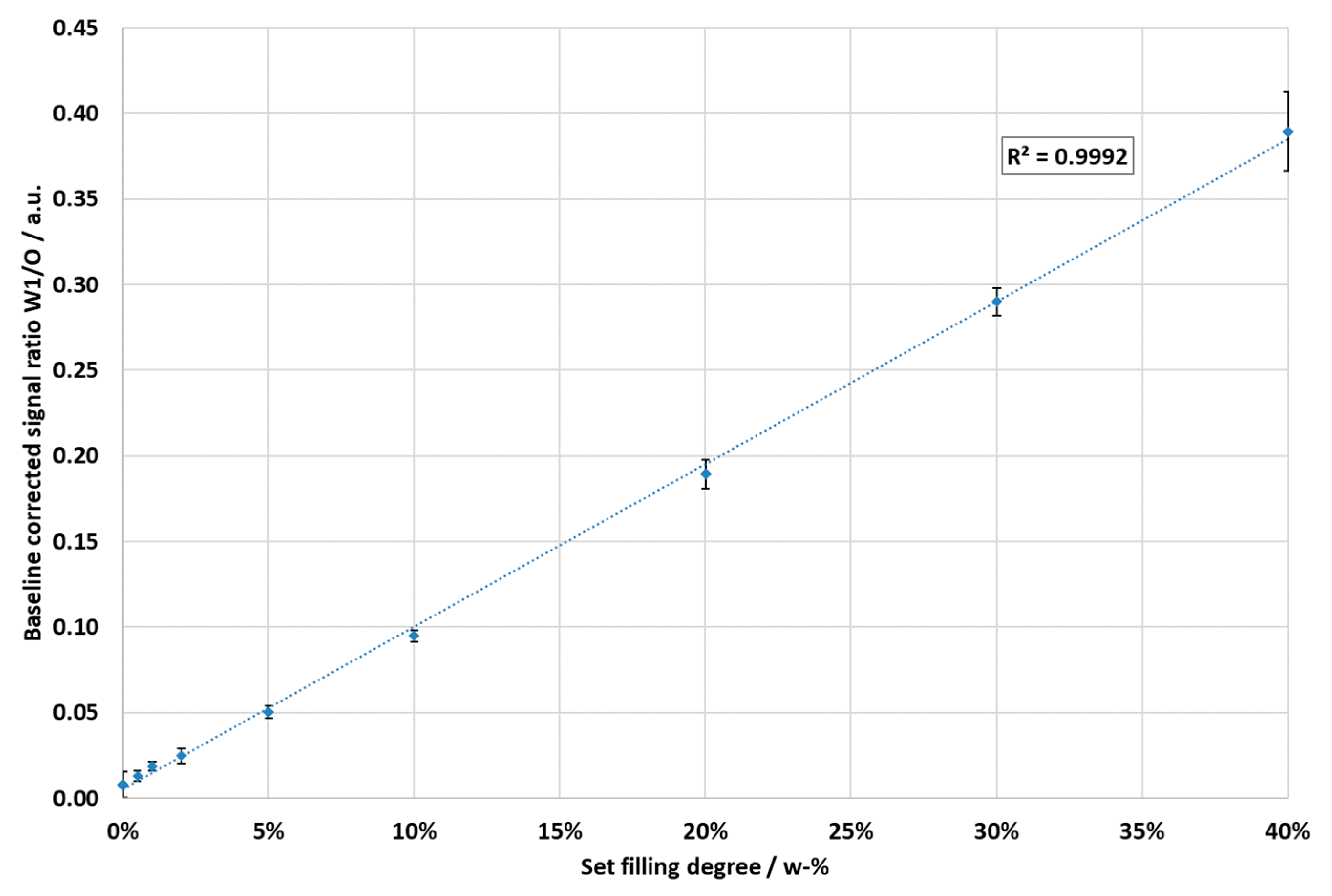
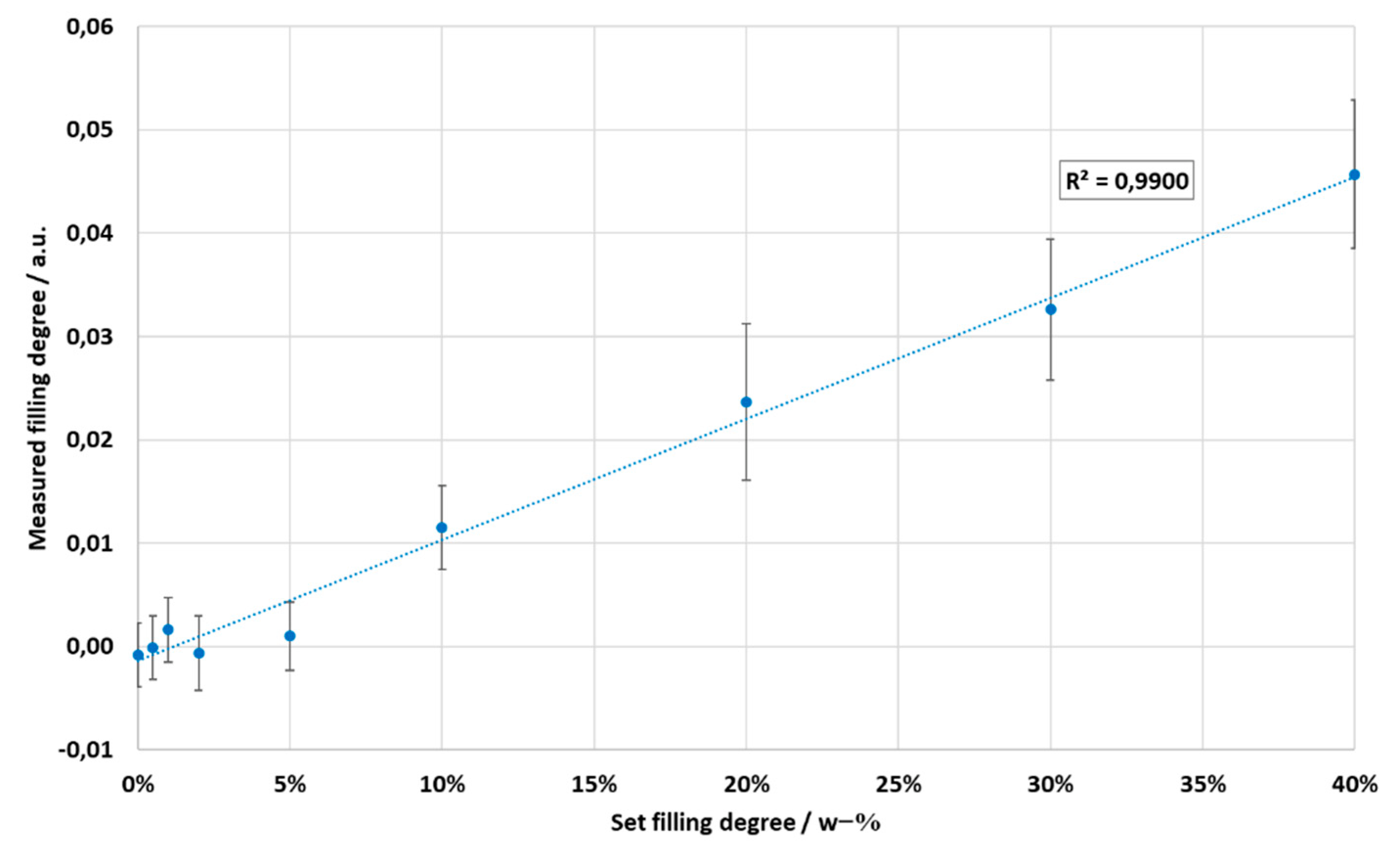
The measurement results together with their calculated Pearson coefficients show that the filling degrees of double emulsions can be measured and distinguished with both Raman measuring methods, i.e., spectroscopically and photometrically.
The data recorded with the spectrometer show almost perfect linearity. The standard deviations decreased with the increasing filling degree. At the 0% filling degree, by far the largest standard deviation of 31.9% was present. This can be explained by the absence of an ammonium nitrate peak, which means that only the signal noise is included in the integral calculation. The larger the ammonium nitrate peak with increasing filling degree, the more constant the integrals and the smaller the standard deviations, i.e., it is method-related, and the measurement accuracy increases with the filling degree of the sample.
The oil integrals hardly varied over all filling degrees, with their maximum standard deviation being 2.0%. This means that they only had a minor influence on the standard deviations of the filling degrees.
The filling degrees calculated from the photometric results showed a slightly worse linearity, with R2 = 0.9900. Accordingly, the filling degrees can also be distinguished with this method, but with a lower sensitivity compared with the spectrometric measurements.
The standard deviations per filling degree were significantly larger for the photometric measurements, which is due to several aspects. For each filling degree, the shortest measured measurement durations were 10–20 ms, corresponding to droplets in the size range of about 20–40 µm. Theoretically, it can be ruled out that these are individual, very small oil droplets that are produced, as oil droplet size values just below the size of the capillary’s inner diameter are to be expected with the co-flow arrangement of the capillaries that were used. In fact, such droplets did not exist in all samples, as could be verified by microscopic images. These measured signals can only be explained by particulate impurities which are present in the continuous phase and reflect the excitation light.
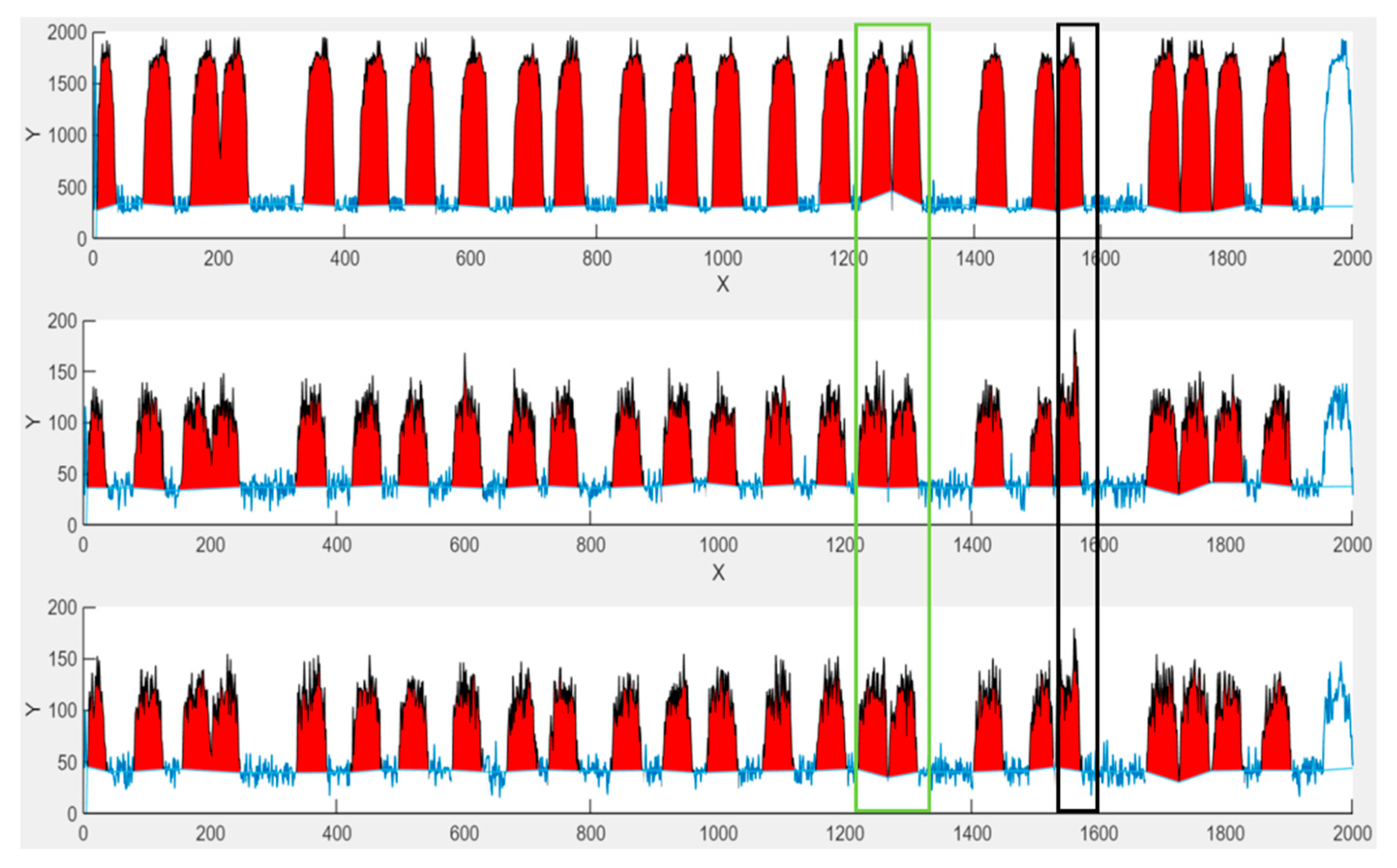
Another reason is the very short integration time of 2 ms. In general, the longer the integration time, the more stable the result. The strong fluctuations can be seen in the section of the evaluated peaks at the 5% filling degree shown in
Figure 9.
Considering both the baselines between the peaks and the areas of the peak maxima, a clear scattering of the measured values can be seen. In addition, the baselines were individually determined for each peak. This disadvantage becomes clear with the double peak that is highlighted by the green rectangle. The double peak results from two drops which were measured in very short succession. Consequently, the baseline was calculated from extremely few measured values. In this case, this results in the slope of the first baseline being positive and the slope of the second baseline being negative for the oil signal. For the inner water phase, both baselines have no significant slope. For the reference, the first baseline has a negative slope, and the second baseline has a positive slope.
In addition to the baselines, there are numerous outliers on the peaks, such as on the peak within the black rectangle. The oil signal has a small outlier in the middle, but it is of this magnitude on most peaks. On the corresponding peaks of the inner water phase and the reference, the outliers are much more pronounced.
Even without outliers, the scattering on all peaks is different and does not follow a pattern. Even between three superimposed peaks that all originate from the measurement of the same droplet, there are differences in the scattering pattern around the peak maxima.
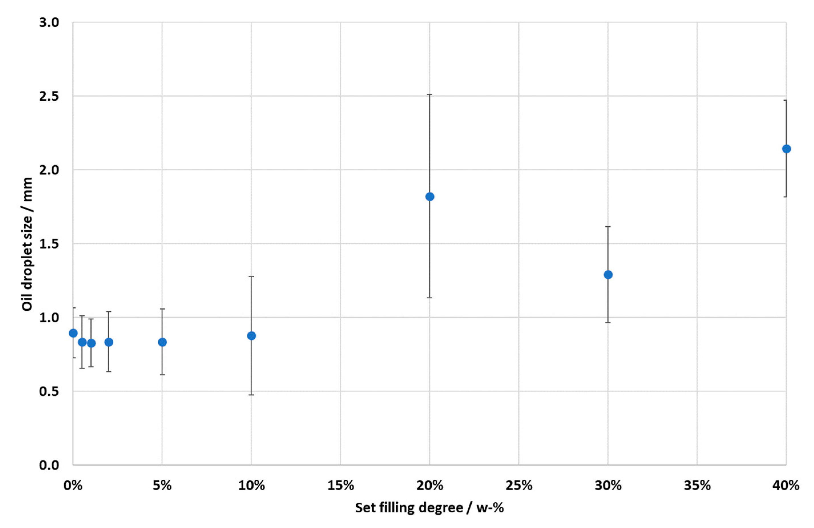
In general, an increase in oil droplet size from the filling degrees above 10% can be explained by the associated increase in the viscosity of the inner emulsion [
9]. The increased viscosity makes it more difficult for the outer phase to break the inner emulsion into double emulsion droplets, which results in increased oil droplet sizes. Up to a filling degree of 10%, the increase in viscosity is small and thus has no significant influence.
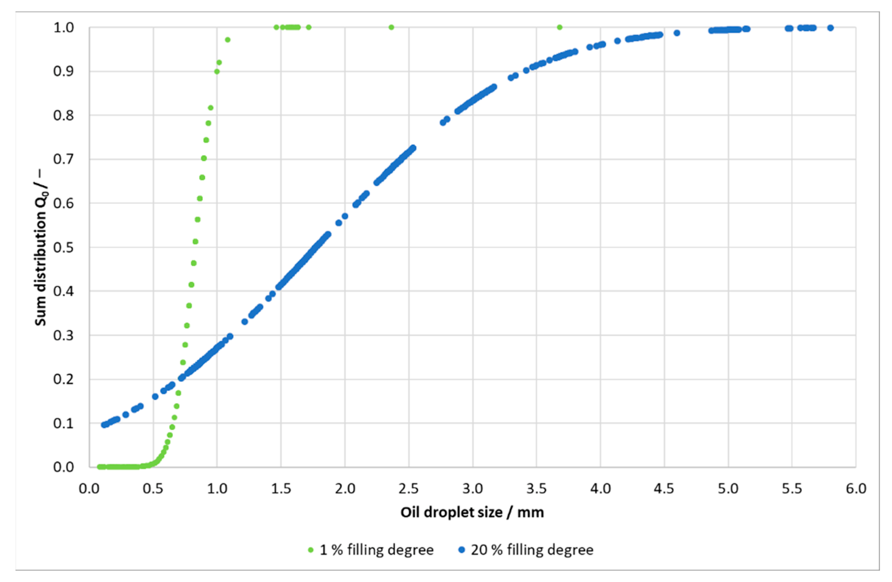
At the 40% filling degree, a uniform drop break-up was no longer possible. Instead, up to five individual droplets formed a droplet chain, which meant that the individual droplets could not be individually measured. This can be seen in
Figure 10, which shows a section of the evaluated oil peaks.
Figure 11 shows a similar behavior of the droplets in the channel for the 20% filling degree. The droplets flow in non-uniform intervals, with some flowing as single droplets, and others in a chain of several droplets.
Based on the droplet chains, which are recognized as one droplet by the software, the significantly larger oil droplet diameters as well as wide oil droplet size distribution can be explained.
5. Conclusions
In summary, both measuring methods are able to measure the filling degree of W/O/W double emulsions. The photometric measurement method can also reliably measure the oil droplet sizes. Which measurement method is more suitable therefore depends on the experimental goal, required accuracy, and budget available.
The spectrometric method should be chosen if information on the droplet size is not important. With this method, filling degrees with a 0.5% difference can be distinguished with high accuracy.
If information on the droplet size is also required, the photometric method must always be used, as only this method measures individual oil droplets. However, this measurement method is subject to greater fluctuations, which is why small percentage differences in the filling degree cannot be as reliably measured here as with the spectrometric method. However, the very short sampling rate of 2 ms, which is the basis of the measurement of each individual drop, has a share in this. In addition, further optimizations to the software, such as a global baseline for all peaks or a minimum measurement duration, could make the results more precise.
