Article

Real-Time Wind Field Estimation and Pitot Tube Calibration Using an Extended Kalman Filter

1
School of Aeronautic Science and Engineering, Beihang University, Beijing 100191, China
2
School of Instrumentation Science and Opto-Electronics Engineering, Beihang University, Beijing 100191, China
*
Author to whom correspondence should be addressed.
Mathematics 2021, 9(6), 646; https://doi.org/10.3390/math9060646
Submission received: 2 March 2021 / Revised: 16 March 2021 / Accepted: 16 March 2021 / Published: 18 March 2021

Abstract

:
The airspeed is an important feedback signal for flight control, and its measurement accuracy is related to the safety of aircraft, especially for hybrid vertical takeoff and landing (VTOL) unmanned aerial vehicles (UAV) in the transition phase. However, offline calibration of the pitot tube cannot fully simulate the situation in real cases, and this is why online calibration after installation is necessary. In addition, the environmental wind field creates a high risk for the conversion flight of a hybrid UAV, thus real-time wind field measurement of the flight field has great significance for the flight path planning of the conversion process. In this article, an innovative method for online calibration of pitot tube and wind field estimation is proposed. After establishing the extended Kalman filter (EKF) for estimation, an analysis method is proposed to analyze the observability of EKF under different flight strategies. Then, the hovering flight is selected as the experimental flight trajectory. The laboratory computer simulation and flight experiment results validate the theory and prove that the proposed method could re-calibrate the scale factor of the pitot tube and estimate the wind field.

1. Introduction

During recent decades, unmanned aerial vehicles (UAVs) have been increasingly used in civil and military applications which include search and rescue operations [1], area mapping [2], weather monitoring [3], and agricultural operations [4]. UAV platforms can be divided into two categories according to flight modes: fixed-wing UAV and rotorcraft UAV [5]. The fixed-wing UAV has advantages of high cruising speed and altitude. Furthermore, the push-to-weight ratio of the fixed-wing UAV is generally less than 0.1, which gives the fixed-wing UAV high flight efficiency. However, fixed-wing UAV needs a runway for reliable takeoff and landing, which imposes restrictions on its applications [6]. On the other hand, rotorcraft UAV can take off and land vertically. For stationary or low speed applications, the rotorcraft UAV has a hovering capability. As the thrust of rotorcraft UAV has to overcome gravity, the push-to-weight ratio needs to be greater than 1, which is the main factor that limits the flight speed and time of rotorcraft UAV [7]. According to the characteristics of the above-mentioned two aircrafts, a new technical approach for hybrid vertical takeoff and landing (VTOL) UAV is proposed which integrates the advantages of fixed-wing and rotorcraft [8,9].
The hybrid VTOL has two independent propulsion systems for hover and level flight. During the vertical take-off and hover phases, the rotor lift system works like a quadrotor and the push system turns off or remains in idle state. The attitude and position are controlled by direct force of the rotor system. During the level flight phase, the rotor lift system is turned off and the aircraft works like a fixed-wing. As the hybrid VTOL is a fusion of fixed-wing UAV and rotorcraft UAV, the conversion process of two flight modes is accompanied by changes in the actuators and control law, and the control accuracy at this stage directly affects the safety of the hybrid VTOL [10,11]. At this phase, the switching criterion of two different control strategies depends on the change of airspeed. Accurate measurement of airspeed is critical to the safety of the conversion process. Generally, airspeed is measured by a pitot tube using the Bernoulli principle and the measurement accuracy is influenced by air density, installation error and operational environment [12]. In addition, the environmental wind field affects the conversion flight of the hybrid UAV by changing the airspeed and may cause the UAV to enter an irretrievable stall [13]. Therefore, the accurate calibration of the pitot tube and real-time wind field measurement of the flight field have great significance for the flight safety of the conversion process of the hybrid VTOL.
Several pitot tube calibration and wind field estimation approaches have been studied. Cooper introduced a calibration method for the pitot tube using a doppler laser air-motion sensor; in this way, the pitot tube could be used independently of any other temperature sensor [14]. Am Cho proposed a Kalman filter method to calibrate the error of airspeed, baro-altitude and side-slip angle due to the position error of the pitot static tube, and the method was verified by being applied to data from a commercial air-data computer [15]. Conley made a low-cost system for measuring horizontal winds, based on a global positioning system (GPS) that provided aircraft heading and a ground-referenced velocity. Then, the horizontal wind velocity was estimated by comparing the ground velocity and standard true airspeed [16]. A real-time wind estimation method was proposed in [17]. In this article, the wind was estimated using on-board sensors only and did not need any additional airspeed sensor or dedicated anemometer. In order to improve the positioning accuracy of quadrotor, Waslander proposed a wind estimation method which relies on the use of the accelerometer data [18]. A single-antenna GPS receiver was used to estimate wind speed and to calibrate the airspeed in [19]. However, this article makes a very limited assumption in that the attack and sideslip angles are ignored and the wind field was assumed to be 2D. Therefore, it cannot be fully applied in actual flight and cannot estimate wind shear information.
In this article, the measurements from an integrated navigation system and pitot tube are used, and a method based on an extended Kalman filter (EKF) for online calibration of airspeed tube and measurement of wind field is proposed. In this way, installation error and environmental error of the pitot tube, which are difficult to calibrate by wind tunnel test, can be calibrated precisely, and real-time measured wind field data is more informative. The algorithm was implemented and evaluated with a computer simulation experiment and actual flight verification.
The article is organized as follows: Section 2 presents the measuring principle of the pitot tube and offline calibration with wind tunnel, together with the experimental results and error analysis. Section 3 introduces the method of wind field measurement and pitot tube calibration. In order to improve measurement accuracy, the flight strategy and observability analysis are discussed. Computer simulations and experimental results are provided and discussed in Section 4, followed by conclusion in Section 5.

2. Measurement Principle and Description of Problem

2.1. Measurement Principle of Pitot Tube

The airspeed is generally obtained by measuring total and static pressure with a pitot tube. As shown in Figure 1, the pitot tube has a total pressure hole and several static pressure holes. The oncoming airflow passing through the pitot tube is divided into two channels. Based on the Bernoulli equation, the relationship between pressure and velocity is:
P 1 + 1 2 ρ 1 V 1 2 = P 2 + 1 2 ρ 2 V 2 2 = c o n s t
As the diameter of the total pressure hole is small, the airflow across the total pressure hole is blocked, and the kinetic energy at this point is completely converted into pressure, therefore, V 2 = 0 . The pressure in the static pressure hole is the same as the atmospheric environment. Therefore, Equation (1) can be rewritten as
P 2 P 3 = 1 2 ρ 1 V 1 2
Equation (2) represents that the airspeed of flight is measured indirectly by the pressure of the relative airflow [20], and the calibration formula can be expressed as:
1 2 ρ V a m 2 K a = Δ P = C f V a m 2 = V o u t
where V a m is the airspeed measured by pitot tube, ρ is the air density, K a is the scale factor, Δ P is the pressure difference and V o u t is the output of the pitot tube sensor. If the environmental errors are constant, the sensor output is proportional to the square of the measured airspeed. Therefore, accuracy calibration of coefficient C f will facilitate accurate measurement of airspeed.

2.2. Description of Problem

Before using the pitot tube, the offline calibration experiment should be made in the wind tunnel. As shown in Figure 2, the pitot tube is installed on the bracket in the wind tunnel. The upwind angle of the pitot tube can be achieved by adjusting the bracket. Then, the two pressure pipes are connected to the deference pressure sensor of the flight control system. By collecting the pitot tube sensor’s data and the wind speed in the wind tunnel, coefficient C f can be calibrated. Figure 3 shows the fitting result.
The output of the deference pressure sensor is given as voltage value. As shown in Figure 3, after fitting the test data, the measured airspeed could be obtained by collecting the voltage signal of the pitot tube sensor.
The cost of calibration in the wind tunnel is very high, and the actual operation process is complicated. Meanwhile, after being calibrated, the pitot tube will be installed on the aircraft. Due to the processing accuracy of the mounting base and mounting errors, the pitot tube cannot be completely parallel to the aircraft’s longitudinal axis, and the non-parallel angle δ may change with different aircraft bodies. As shown in Figure 4, the body frame is defined as O b X b Y b Z b , where O b is the center of gravity, with X b pointing to the front of the aircraft, Y b pointing right and Z b pointing down. The relationship between body frame and air frame can be obtained with attack angle α and sideslip β
[ u v w ] = [ cos α cos β cos α sin β sin α sin β cos β 0 sin α cos β sin α sin β cos α ] [ V a 0 0 ]
Then, the airspeed component measured by pitot tube is
V a m = u cos δ = V a cos α cos β cos δ
It is clear that the measured airspeed is affected by the attack angle, the sideslip angle, and the installation angle, and these effects cannot be considered during the offline calibration. Furthermore, the coefficient C f is the function of air density ρ and temperature T , and it will vary with different aircraft operating conditions. Therefore, an online calibration method that avoids the high cost of offline operation and takes into account the actual operating conditions of the pitot tube should be proposed.
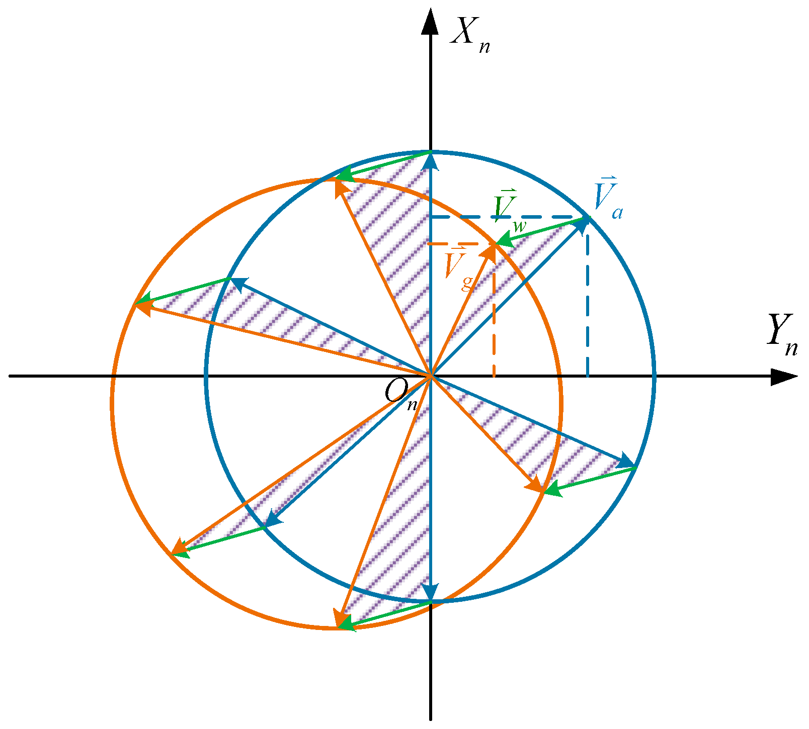
The accurate calibration of the pitot tube cannot be separated from the accurate measurement of real-time airspeed. However, the airspeed is closely related to ground speed and wind speed. As shown in Figure 5, two-dimensional horizontal velocity is considered. The yaw angle of the target airspeed vector changes at a constant angular speed over time and the absolute value is constant. Due to the presence of wind field, the absolute value of ground speed varies from the yaw angle. Therefore, the wind field affects the shape of the speed triangle and needs to be considered during the calibration of the pitot tube.

3. Pitot Tube Calibration and Wind Field Measurement

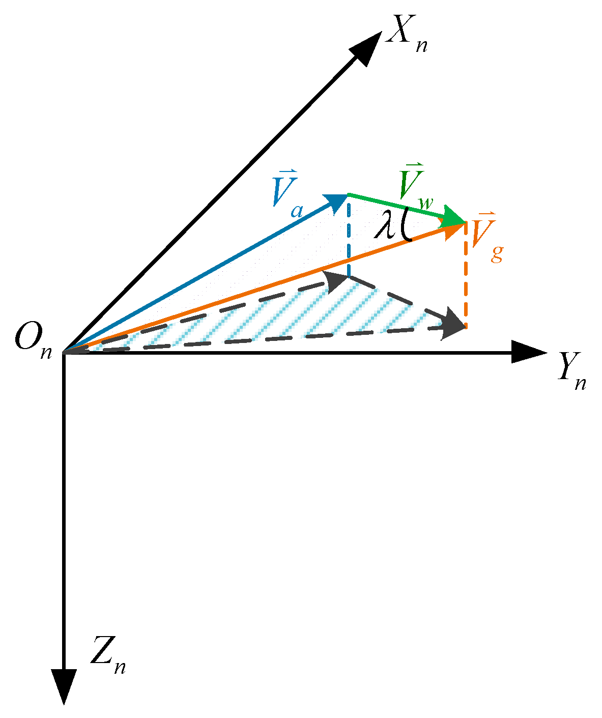
The local-level north-east-down (NED) frame is selected as the navigation frame (n frame). The three-dimensional speed triangle is shown in Figure 6 and it satisfies the following formula
V g 2 + V w 2 2 | V g | | V w | cos λ = V a 2
where V g is the ground speed and V w is the wind speed. Considering Equation (3) and Equation (5), Equation (6) can be rewritten as:
V g x 2 + V g y 2 + V g z 2 + V w x 2 + V w y 2 + V w z 2 2 V g V w = V o u t C f ( cos α cos β ) 2
where C f is the coefficient which includes the influence of installation error and operational environment. V g V w is the inner product of V g and V w . Because the attack angle and sideslip angle in Equation (7) are small values, they can be calculated by the speed in the body frame
α = tan 1 ( w u )
β = tan 1 ( v u 2 + v 2 + w 2 )
The speed in body frame can be obtained by attitude transformation matrix and ground speed
[ u v w ] = [ cos θ cos ψ cos θ sin ψ sin θ sin θ cos ψ sin ϕ sin ψ cos ϕ sin θ sin ψ sin ϕ + cos ψ cos ϕ cos θ sin ϕ sin θ cos ψ c o s ϕ + sin ψ sin ϕ sin θ sin ψ cos ϕ cos ψ sin ϕ cos θ cos ϕ ] [ V g x V g y V g z ]
where the roll angle ϕ , pitch angle θ , yaw angle ψ and ground speed V g * can all be obtained by the integrated navigation system of UAV.

3.1. Design of Extended Kalman Filter

According to Equations (7)–(10), an EKF method is proposed to estimate the parameter of the pitot tube and wind field information. The Kalman filter is a linear quadratic estimation (LQE) algorithm. When a system has a series of measurements with errors, the Kalman filter can estimate unknown variables with these measurements and obtain more accurate variables than those based on a single measurement alone [21,22]. For computer applications, the Kalman filter is always expressed in discrete linear form as in the following equations
{ X k = Φ k , k 1 X k 1 + Γ k 1 W k 1 Z k = H k X k + V k + f k , φ γ
where Z k R m is the measure of the output, X k R n represents the system state, Φ k , k 1 R n × n is the one step transfer matrix of system state, and Γ k 1 R n × r is the noise matrix. W k R r and V k R m are independent Gaussian white noise sequence
E { W k } = 0 , E { W k W j T } = Q k δ k j
E { V k } = 0 , E { V k V j T } = R k δ k j
where δ k j is Krone Nick function, and γ is a random vector which presents the size of the fault. f k , φ is a piecewise function can be described as
f k , φ = { 1 , k φ 0 , k < φ
According to the Equation (7), the state vector is defined as x ¯ = [ V w x , V w y , V w y , C f ] T . As the UAV’s flight time is short, the wind field can be considered as constant. Then the one step transfer matrix can be described as
Φ k , k 1 = [ 1 0 0 0 0 1 0 0 0 0 1 0 0 0 0 1 ]
The measurement vector is the output of the pitot tube and it can be deduced from Equation (7)
V o u t = C f ( cos α cos β ) 2 ( V g x 2 + V g y 2 + V g z 2 + V w x 2 + V w y 2 + V w z 2 2 ( V g x V w x + V g y V w y + V g z V w z ) )
The linearized measurement matrix can be expressed as
H = [ h V w x h V w y h V w z h C f ] T = [ C f ( cos α cos β ) 2 ( 2 V w x 2 V g x ) C f ( cos α cos β ) 2 ( 2 V w y 2 V g y ) C f ( cos α cos β ) 2 ( 2 V w z 2 V g z ) ( cos α cos β ) 2 ( V g x 2 + V g y 2 + V g z 2 + V w x 2 + V w y 2 + V w z 2 2 ( V g x V w x + V g y V w y + V g z V w z ) ) ]

3.2. Design of Flight Scheme and Observability Analysis

In this section, the observability analysis method is introduced to analyze the observable degrees of state estimation. In this way, the flight strategy can be designed in advance to make the state estimation more accurate and efficient.
As the measurement matrix of the EKF is time-varying, the traditional observability analysis method cannot be used directly. The piece-wise constant system (PWCS) observability analysis method was first proposed by Goshen-Meskin in 1992 [23]. This method divides the time-varying system into several sections which can be approximately considered as constant systems in a short enough time interval. Then, a stripped observability matrix (SOM) is introduced to realize observability analysis.
For the discrete system model shown in Equation (11), the PWCS can be expressed as:
{ X k = Φ j X k 1 + Γ k 1 W k 1 Z k j = H j X k + V k + f k , φ γ
where j = 1 , 2 , 3 r are the different time periods. In each time period, Φ j and H j are all constant. Then, all observations can be expressed as functions of X 1
{ Z 1 1 = H 1 X 1 Z 2 1 = H 1 F 1 X 1 Z n 1 = H 1 ( F 1 ) n 1 X 1 Z n 2 = H 2 ( F 1 ) n 1 X 1 Z n + 1 2 = H 2 F 2 ( F 1 ) n 1 X 1 Z 2 n 2 = H 2 ( F 2 ) n 1 ( F 1 ) n 1 X 1 Z 2 n 3 = H 3 ( F 2 ) n 1 ( F 1 ) n 1 X 1 Z 2 n + 1 3 = H 3 F 3 ( F 2 ) n 1 ( F 1 ) n 1 X 1
The SOM can be written as,
Q S O M = [ [ H 1 H 1 F 1 H 1 ( F 1 ) n 1 ] T [ H 2 H 2 F 2 H 2 ( F 2 ) n 1 ] T [ H k H k F k H k ( F k ) n 1 ] T ]
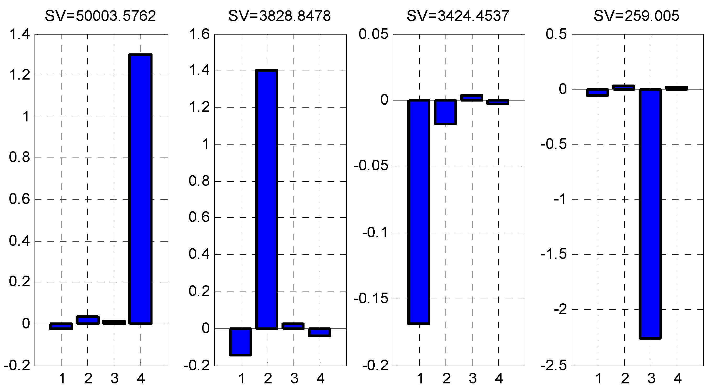
The SOM can analyze the observability of the system; however, the observability of each variable cannot be analyzed. Therefore, a singular value decomposition (SVD) analysis method is carried out to calculate the observable degree of each filter state [24]. Based on SVD theory, the SV reflects the observability of each state. The greater the SV value, the higher the observable degree of the corresponding state [25]. Therefore, by comparing the SVD of different flight strategies, the optimal flight trajectory can be obtained. Here, straight flight and circle flight are analyzed as two typical flight strategies.
Figure 7 and Figure 8 give the histograms of SVD analysis of straight flight and circle flight. No.1, 2, 3 and 4 represent the singular value of V w x , V w y , V w z , C f , respectively. It can be seen that each flight strategy is observable for the state vector, and the similar singular values represent similar observable degrees of state. These two figures also show that the observability of each state of circle flight is greater than that of straight flight. The singular values of V w x for the two typical flight strategies are similar, because the installation of the pitot tube is parallel to the longitudinal axis of the aircraft, mainly to measure the velocity in this direction. The singular values of the other three states of straight flight are smaller than those of circle flight, especially for the singular values of vertical wind speed and scale factor, which means the observable degrees of straight flight are worse. Because the measurement direction of the pitot tube can be at any angle to the horizontal wind speed in the circle flight strategy, the observability of the state is improved. The observability analysis results prove that circle flight is better for state estimation. Therefore, the circle flight strategy is used in the next experimental section.

4. Simulation and Experiments

4.1. Computer Simulation Results

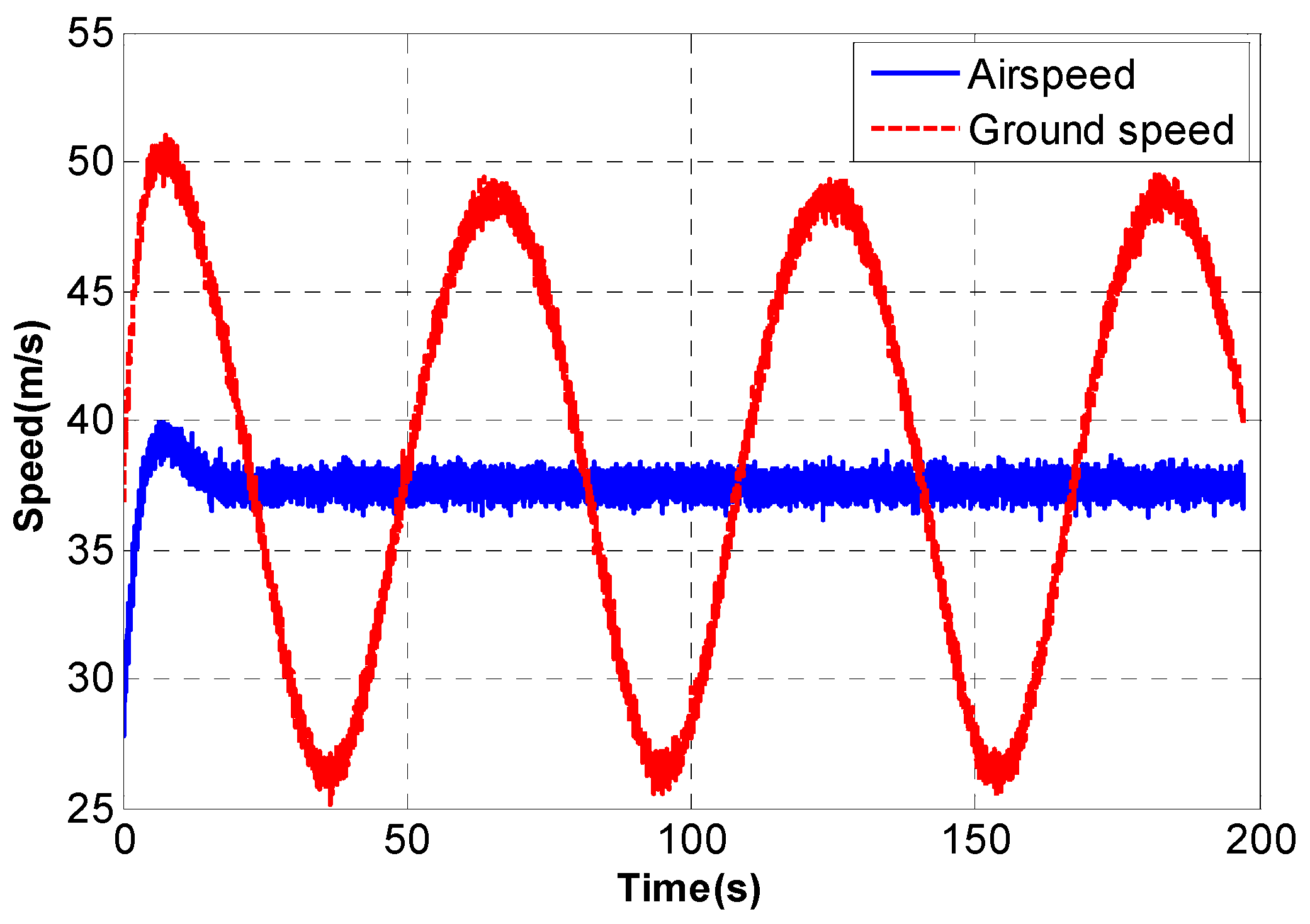
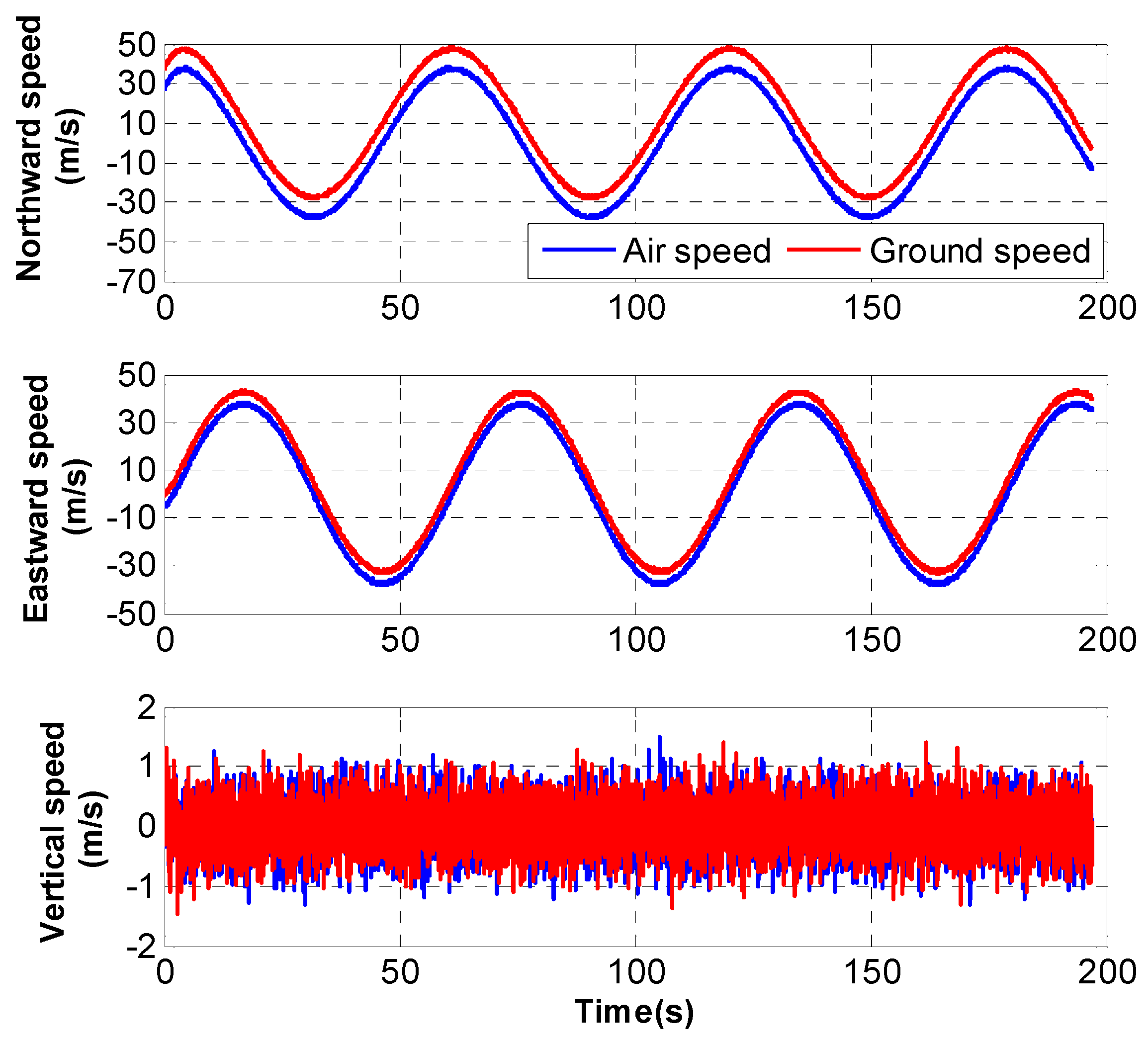
According to the above analysis, the computer simulation test is performed before the actual flight verification. The simulation is done with a Matlab2014.8.3.0 program on an Intel Core i7 Duo processor. In the simulation flight strategy, the aircraft makes a circular hovering motion around a fixed point on the ground. If there is no wind, the airspeed and ground speed are consistent. As shown in Figure 9, if there is constant wind at the flight site, the ground speed needs to be changed to ensure airspeed is constant. Figure 10 depicts the profiles of airspeed and ground speed.
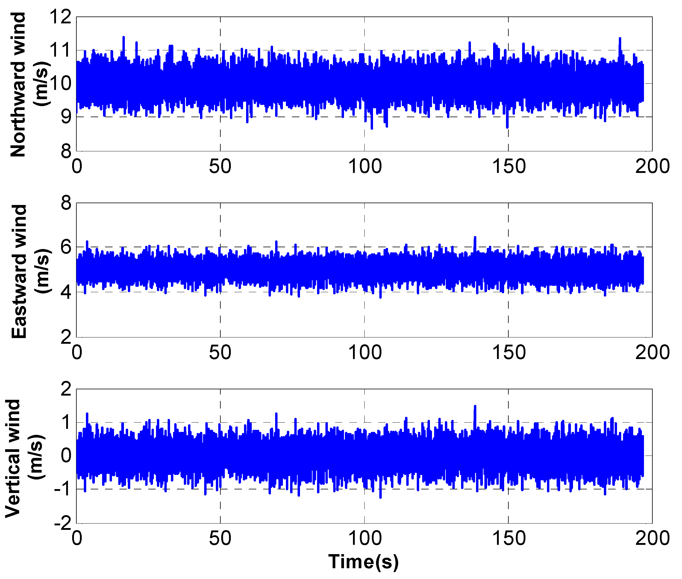
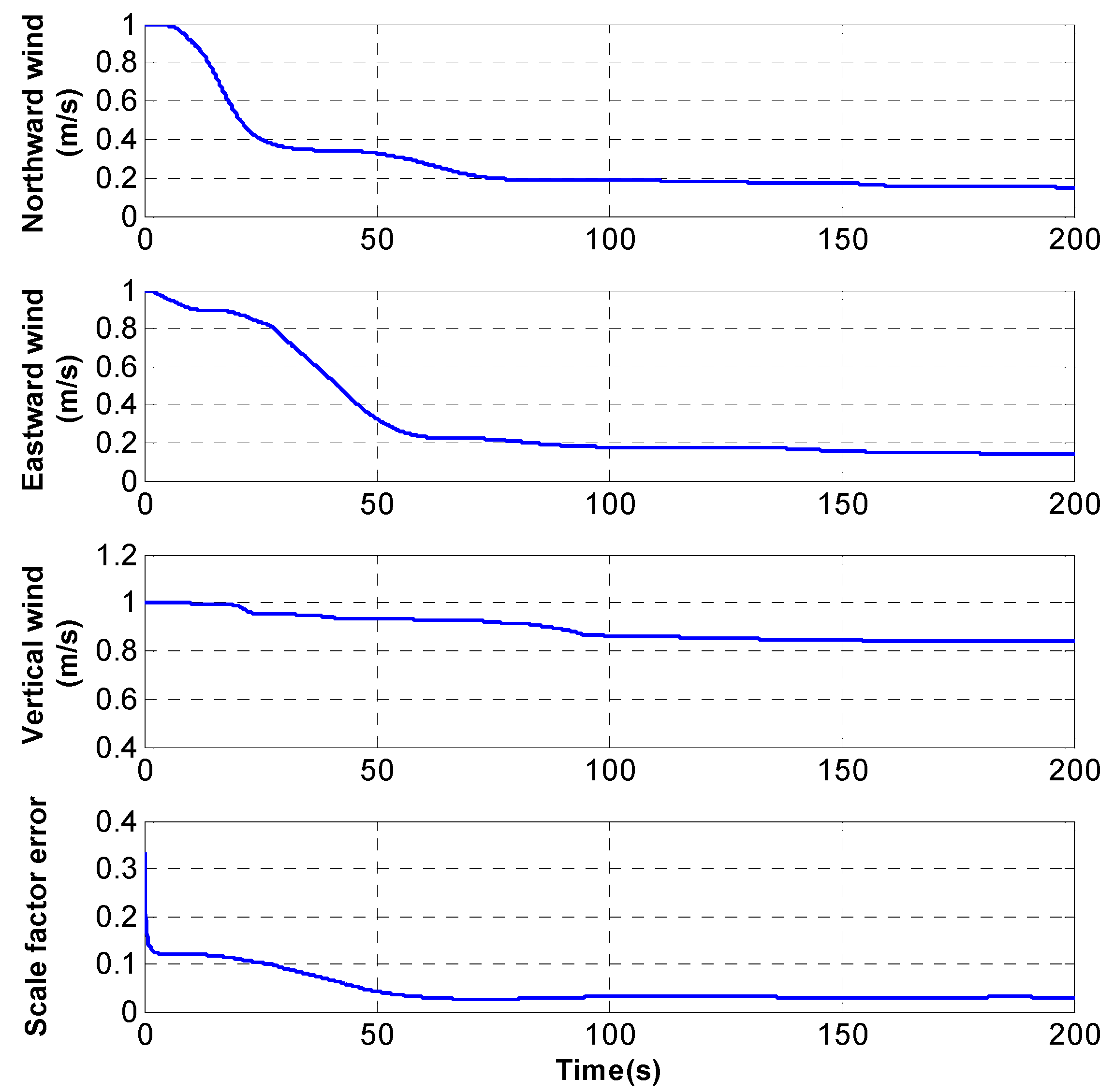
In the computer simulation, the weight of the aircraft is 60 kg and horizontal cruising speed is about 38 m/s. It is assumed that the northward and eastward wind speeds are 10 m/s and 5 m/s, the vertical speed is zero and the scale factor is 0.8. The wind speed profile is described in Figure 11. The hovering radius is 350 m and it takes about one minute to circle. The aircraft starts with zero yaw and circles clockwise from zero time. As shown in Figure 9, with the influence of the wind field, ground speed changes around the airspeed with time. The estimation result is shown in Figure 12 and it is obvious that the wind speeds converge quickly and the estimation result of the scale factor is also accurate.

4.2. Actual Flight Verification

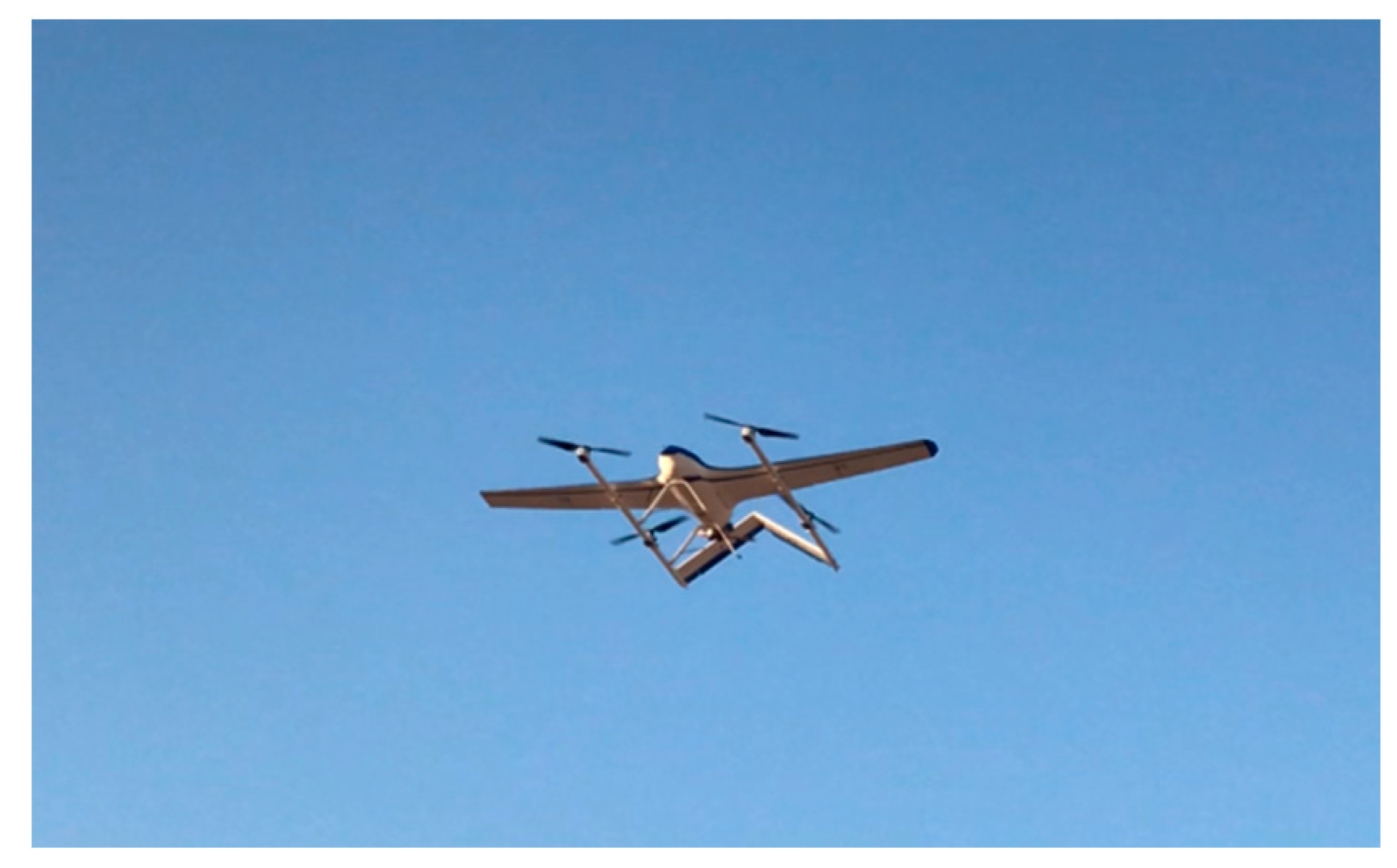
To verify the dynamic performance of the system, a real flight experiment is carried out. The method is verified on a hybrid VTOL, HQ10. The experimental system is composed of an on-board system and a ground station system, as shown in Figure 13. The flight control system with inertial measurement unit (IMU) and real-time kinematic (RTK) can measure the accuracy navigation states, and give the control command to HQ10. The ground display and control system communicate with the flight control system through the digital radio.
As shown in Figure 14, the HQ10 is equipped with four rotor motors with maximum force of 30 kgf and a 150 cc gasoline engine. The RTK equipment and inertial navigation system (INS) are installed on the airplane and the horizontal positioning accuracy is less than one meter. During algorithm verification, the ground speed and attitude are obtained by the RTK-INS integrated navigation system and the pitot tube data is obtained by the differential pressure transducer MS4525DO.
The HQ10 is commanded to fly around a fixed point with the 350 m radius at a constant height. The EKF is used when the aircraft enters a fixed altitude circle. Figure 15 shows the roll, pitch and yaw angle throughout the flight. Due to the existence of the wind field, the aircraft needs to periodically adjust the roll angle when it hovers around a fixed point.
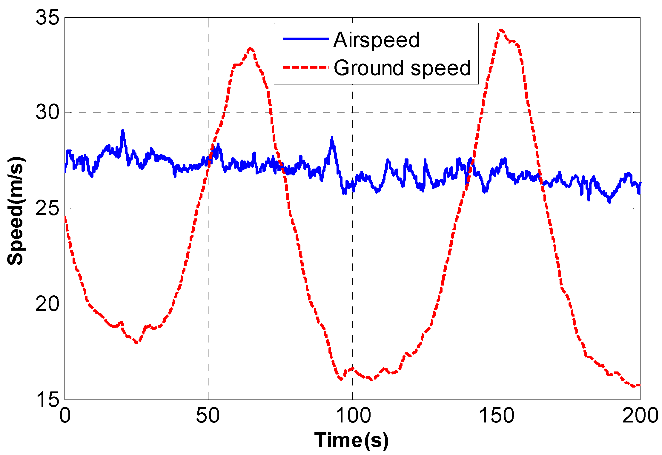
As shown in Figure 16, during the hovering flight, the airspeed is maintained at a fixed value and ground speed fluctuates with the angle of hovering flight based on the airspeed. The estimation results are shown in Figure 17 and Figure 18. The EKF estimator has converged after 100 s, and the northward and eastward wind speeds finally converge to −3.8 m/s and 7.1 m/s, and the vertical wind is relatively small. As the pitot tube has been calibrated offline, the average value of scale factor is approximately 1.2.

5. Conclusions

In this article, an innovative method is proposed to estimate the calibration error of the pitot tube and environmental wind field. As the offline calibration of the pitot tube using a wind tunnel does not consider the actual usage condition, the scale factor error needs to be re-calibrated in actual flight. Therefore, an extended Kalman filter is obtained by using the integrated navigation system and differential pressure transducer. Before experimental verification, observability analysis is researched to prove that hovering flight has a greater ability to estimate state variables. Computer simulation and experimental results show that the proposed method can estimate the scale factor of pitot tube and wind speed in circle flight. It can be seen from the actual flight results that the estimator can converge in about 100 s which is approximately equal to the time it takes for the aircraft to fly one lap. This method can optimize the measurement accuracy of the pitot tube on the basis of the offline calibration process and is more practical in combination with the actual flight conditions of the aircraft. However, the estimation algorithm discussed in this article is based on an accurate integrated navigation system. Therefore, the influence mechanism of navigation errors on wind field and scale factor estimation needs further research in future works.

Author Contributions

Conceptualization, Q.Z. and Y.X.; methodology, Q.Z.; software, Q.Z. and T.D.; validation, Q.Z., Y.X. and X.W.; formal analysis, Q.Z.; investigation, Q.Z.; resources, Y.X.; data curation, Y.X.; writing—original draft preparation, Q.Z.; writing—review and editing, Q.Z.; visualization, X.W.; supervision, Z.Y. and T.D.; project administration, X.W.; funding acquisition, X.W. All authors have read and agreed to the published version of the manuscript.

Funding

The work described in this article was partially supported by Beijing Natural Science Foundation Project (4204103) and Aeronautical Science Foundation of China (2019ZC051009).

Institutional Review Board Statement

Not applicable.

Informed Consent Statement

Not applicable.

Data Availability Statement

Not applicable.

Acknowledgments

The authors are grateful to Xu Liang for providing the dataset used in the experiments.

Conflicts of Interest

The authors declare no conflict of interest. The funders had no role in the design of the study; in the collection, analyses, or interpretation of data; in the writing of the manuscript, or in the decision to publish the results.

References

  1. Mostafa, E.; Fu, L.; Ibrahim, A.; Usman, A. A solution of UAV localization problem using an interacting multiple nonlinear fuzzy adaptive H-infinity models filter algorithm. Chin. J. Aeronaut. 2019, 32, 978–990. [Google Scholar] [CrossRef]
  2. Shakhatreh, H.; Sawalmeh, A.H.; Al-Fuqaha, A.; Dou, Z.C.; Almaita, E.; Khalil, I.; Othman, N.S.; Khreishah, A.; Guizani, A.M. Unmanned Aerial Vehicles (UAVs): A Survey on Civil Applications and Key Research Challenges. IEEE Access 2019, 7, 48572–48634. [Google Scholar] [CrossRef]
  3. Liu, C.; Ai, M.C.; Zhou, C.; Zhou, Y.; Wu, H.B. Detection of Firmiana Danxiaensis Canopies by a Customized Imaging System Mounted on an UAV Platform. J. Sens. 2018, 2018, 6869807. [Google Scholar] [CrossRef] [Green Version]
  4. Tran, H.K.; Chiou, J.S.; Dang, V.H. New Fusion Algorithm-Reinforced Pilot Control for an Agricultural Tricopter UAV. Mathematics 2020, 8, 1499. [Google Scholar] [CrossRef]
  5. Gu, H.W.; Lyu, X.M.; Li, Z.X.; Shen, S.J.; Zhang, F. Development and Experimental Verification of a Hybrid Vertical Take-Off and Landing (VTOL) Unmanned Aerial Vehicle (UAV). In Proceedings of the 2017 Inernational Conference on Unmanned Aircraft Systems, Miami, FL, USA, 13–16 June 2017; pp. 160–169. [Google Scholar]
  6. Schellenberg, B.; Richardson, T.; Richards, A.; Clarke, R.; Watson, M. On-Board Real-Time Trajectory Planning for Fixed Wing Unmanned Aerial Vehicles in Extreme Environments. Sensors 2019, 19, 4085. [Google Scholar] [CrossRef] [PubMed] [Green Version]
  7. Dulf, E.H.; Saila, M.; Muresan, C.I.; Miclea, L.C. An Efficient Design and Implementation of a Quadrotor Unmanned Aerial Vehicle Using Quaternion-Based Estimator. Mathematics 2020, 8, 1829. [Google Scholar] [CrossRef]
  8. Saeed, A.S.; Younes, A.B.; Cai, C.X.; Cai, G.W. A survey of hybrid Unmanned Aerial Vehicles. Prog. Aerosp. Sci. 2018, 98, 91–105. [Google Scholar] [CrossRef]
  9. Carlson, S. A Hybrid Tricopter/Flying-Wing VTOL UAV. In Proceedings of the 52nd Aerospace Sciences Meeting, National Harbor, Maryland, 13–17 January 2014; pp. 1–11. [Google Scholar]
  10. Saeed, A.S.; Younes, A.B.; Islam, S.; Dias, J.; Seneviratne, L.; Cai, G.W. A Review on the Platform Design, Dynamic Modeling and Control of Hybrid UAVs. In Proceedings of the 2015 International Conference on Unmanned Aircraft Systems, Denver, CO, USA, 9–12 June 2015; pp. 806–815. [Google Scholar]
  11. Ducard, G.; Hua, M. Modeling of an Unmanned Hybrid Aerial Vehicle. In Proceedings of the 2014 IEEE Conference on Control Applications, Antibes, France, 8–10 October 2014; pp. 1011–1016. [Google Scholar]
  12. Hansen, S.; Blanke, M. Diagnosis of Airspeed Measurement Faults for Unmanned Aerial Vehicles. IEEE Trans. Aerosp. Electron. Syst. 2014, 50, 224–239. [Google Scholar] [CrossRef] [Green Version]
  13. Mallaun, C.; Giez, A.; Baumann, R. Calibration of 3-D wind measurements on a single-engine research aircraft. Atmos. Meas. Tech. 2015, 8, 3177–3197. [Google Scholar] [CrossRef] [Green Version]
  14. Cooper, W.A.; Spuler, S.M.; Spowart, M.; Lenschow, D.H.; Friesen, R.B. Calibrating airborne measurements of airspeed, pressure and temperature using a Doppler laser air-motion sensor. Atmos. Meas. Tech. 2014, 7, 3215–3231. [Google Scholar] [CrossRef] [Green Version]
  15. Cho, A.; Kang, Y.S.; Park, B.J.; Yoo, C.S.; Koo, S.O. Air data system calibration using GPS velocity information. In Proceedings of the 2012 12th International Conference on Control, Automation and Systems, Jeju Island, Korea, 17–21 October 2012; pp. 433–436. [Google Scholar]
  16. Conley, S.A.; Faloona, I.C.; Lenschow, D.H.; Karion, A.; Sweeney, C. A Low-Cost System for Measuring Horizontal Winds from Single-Engine Aircraft. J. Atmos. Ocean Tech. 2014, 31, 1312–1320. [Google Scholar] [CrossRef]
  17. Neumann, P.P.; Bartholmai, M. Real-time wind estimation on a micro unmanned aerial vehicle using its inertial measurement unit. Sens. Actuators A Phys. 2015, 235, 300–310. [Google Scholar] [CrossRef]
  18. Waslander, S.L.; Wang, C. Wind Disturbance Estimation and Rejection for Quadrotor Position Control. In Proceedings of the AIAA Infotech@Aerospace Conference and AIAA Unmanned, Seattle, WA, USA, 6–9 April 2009; pp. 1–14. [Google Scholar]
  19. Cho, A.; Kim, J.; Lee, S.; Kee, C. Wind Estimation and Airspeed Calibration using a UAV with a Single-Antenna GPS Receiver and Pitot Tube. IEEE Trans. Aerosp. Electron. Syst. 2011, 47, 109–117. [Google Scholar] [CrossRef]
  20. Crowley, C.; Shinder, I.I.; Moldover, M.R. The effect of turbulence on a multi-hole Pitot calibration. Flow Meas. Instrum. 2013, 33, 106–109. [Google Scholar] [CrossRef]
  21. Huang, W.; Su, X.X. Design of a Fault Detection and Isolation System for Intelligent Vehicle Navigation System. Int. J. Navig. Obs. 2015, 2015, 279086. [Google Scholar] [CrossRef] [Green Version]
  22. Ahmeid, M.; Armstrong, M.; Gadoue, S.; Al-Greer, M.; Missailidis, P. Real-Time Parameter Estimation of DC-DC Converters using a Self-tuned Kalman Filter. IEEE Trans. Power Electron. 2017, 32, 5666–5674. [Google Scholar] [CrossRef] [Green Version]
  23. Goshen-Meskin, D.; Bar-Itzhack, I.Y. Observability analysis of piece-wise constant systems. IEEE Trans. Aerosp. Electron. Syst. 1992, 28, 1056–1067. [Google Scholar] [CrossRef]
  24. Fernando, T.; Jennings, L.; Trinh, H. Numerical implementation of a Functional Observability algorithm: A Singular Value Decomposition Approach. In Proceedings of the 2010 IEEE Asia Pacific Conference on Circuits and Systems, Kuala Lumpur, Malaysia, 27 May 2010; pp. 796–799. [Google Scholar]
  25. Song, T.X.; Li, K.; Sui, J.; Liu, Z.J.; Liu, J.C. Self-calibration method of inner lever-arm parameters for tri-axis RINS. Meas. Sci. Technol. 2017, 28, 1–10. [Google Scholar] [CrossRef] [Green Version]
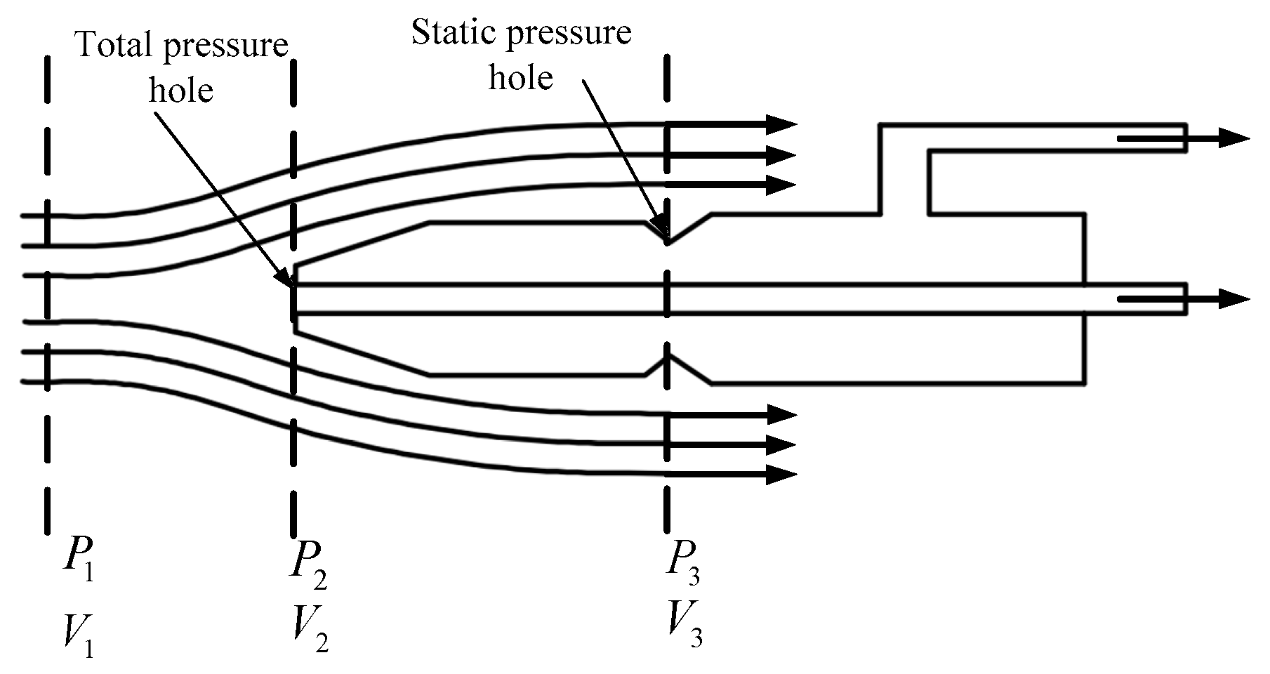
Figure 1. Schematic of pitot tube.
Mathematics 09 00646 g001
Figure 2. The offline calibration experimental equipment.
Mathematics 09 00646 g002
Figure 3. Fitting result of offline calibration.
Mathematics 09 00646 g003
Figure 4. The relationship between air frame and body frame.
Mathematics 09 00646 g004
Figure 5. The relationship between airspeed, ground speed and wind speed.
Mathematics 09 00646 g005
Figure 6. Three-dimensional velocity triangle.
Mathematics 09 00646 g006
Figure 7. Histograms of singular valued decomposition (SVD) analysis of straight flight.
Mathematics 09 00646 g007
Figure 8. Histograms of SVD analysis of circle flight.
Mathematics 09 00646 g008
Figure 9. The airspeed and ground speed during the hovering flight.
Mathematics 09 00646 g009
Figure 10. The speed profiles of airspeed and ground speed.
Mathematics 09 00646 g010
Figure 11. The wind speed set in computer simulation.
Mathematics 09 00646 g011
Figure 12. The estimation results of wind speed and scale factor.
Mathematics 09 00646 g012
Figure 13. Block diagram of the experimental system.
Mathematics 09 00646 g013
Figure 14. The hybrid vertical takeoff and landing (VTOL) HQ10.
Mathematics 09 00646 g014
Figure 15. Attitudes of the HQ10 during the hovering flight.
Mathematics 09 00646 g015
Figure 16. The airspeed and ground speed during the actual flight.
Mathematics 09 00646 g016
Figure 17. The actual estimation results of wind speed and scale factor.
Mathematics 09 00646 g017
Figure 18. The state mean square error of extended Kalman filter (EKF).
Mathematics 09 00646 g018
Publisher’s Note: MDPI stays neutral with regard to jurisdictional claims in published maps and institutional affiliations.