1. Introduction
The growing trend of energy consumption in the world, scarcity of land for installation of onshore wind turbines and drawbacks of fossil fuels usage are the incentives for improvement of energy harvesting projects based on clean and renewable energies in oceans [
1,
2]. Offshore wind and wave resources are considered to be two forms of clean and renewable energies with vast area for deployment [
3,
4]. FOWTs have become an emerging trend in wind energy exploration in the past few years [
5,
6,
7]. They offer the possibility of cheap and clean power supply for highly populated countries with access to a deep offshore area, such as coastal cities in the US, Spain, Japan, Korea, Norway, and Morocco [
8,
9]. Also, FOWTs are being built to have a capability of adding wave energy converters [
10]. One of the most investigated class is the OWC [
11,
12].
The combination of a FOWT and an OWC has a great potential to harness both renewable energies from wind and wave resources. Potential energies of 350 GW from wind and 320 GW from waves can be harvested in the European coasts, which is equivalent to 50% from Wind, 46% from waves and 4% from tidal [
13]. A hybrid FOWT-OWCs system can reduce the system’s balancing costs [
14], smooth power output [
15], decrease the cost of offshore wind power energy [
16] and increase the efficiency of the system. Moreover, common grid infrastructure, shared logistics, shared operation and maintenance are taken into account as some advantages of the combined system [
13].
However, FOWTs need to be stabilized since platform motion is undesirable. It makes the rotor aerodynamics and control more complex and reduces aerodynamic efficiency [
17]. Additionally, platform motion increments stresses on the blades, rotor shaft, yaw bearing, and tower base [
18] and it can reduce the tower lifespan. FOWT’s platform motions in pitch, roll and heave must be limited within acceptable range [
19]. Some researchers hypothesized that the platform stabilization may decrease the platform steel mass, active ballast or/and taut mooring lines [
20].
To harness the maximum energy from FOWTs, platform stabilization and vibration reduction are required [
21]. Several previous articles proposed different approaches to reduce the oscillations in FOWTs. In Reference [
22], Z. Zhang et al. proposed a generator model to provide a feedback control torque to suppress the lateral tower vibrations in offshore wind turbines. W. Yang et al. [
23] used motion stabilizers as heave plates connected to the foundation of the spar-type FOWT for the stabilization. Several articles investigated the application of inerters to a barge-type FOWT to mitigate loads of the FOWTs exposed by winds and waves [
24]. Y. Zhang et al. in [
25] discussed a nonlinear dynamic model of a FOWT equipped with Tuned Mass Damper (TMD) and controlled by sliding mode algorithm. X. Wei et al. in [
26] mitigated the barge pitch and roll motions of floating hydrostatic wind turbine by combining the advantages of the bidirectional tuned liquid column damper and the tuned mass damper.
There are many articles using combined FOWT and Wave Energy Converters (WEC) to create a multi-purpose platform that absorbs both wind and wave energies [
27,
28,
29,
30,
31]. However, there are a few articles proposing OWCs included in FOWTs with stabilization as the main objective. In References [
19,
20], J.M. Kluger et al. combined a spar platform known as OC3-Hywind FOWT with WEC array to reduce its oscillations. A. Slocum et al. in [
32] compared an external and internal heave WEC on OC3-Hywind FOWT. M. Kamarlouei et al. in [
33], concluded that installation of a WEC array can reduce the FOWT platform motions in heave and pitch. However, the introduced approaches have not used OWCs in barge-based FOWT platforms.
Although OWCs have been applied in different FOWTs especially spar-type ones to decrease the motions, the application of OWCs in barge-based FOWTs for stabilization has not yet been reported. This work aims to study the nonlinear model of NREL 5-MW baseline ITI Energy barge wind turbine. The FOWT model is fully coupled aero-hydro-servo-elastic described in frequency domain [
34]. A novel platform design has been proposed in this work to reduce the undesired oscillating motions of the floating platform, particularly in rotational modes. The standard barge platform design has been redesigned to house four OWCs to reduce the oscillations in the barge platform. Performance analysis of the system has been evaluated in frequency and time domains. To achieve this goal, RAOs for platforms’ modes have been analyzed to understand the behaviour of the system in frequency domain and then four periods from the obtained RAOs have been chosen to analyze the system in time domain. A comparison between both standard barge platform and the proposed platform with four OWCs has been provided to evaluate the platforms’ performance.
The structure of this article is organized as follows.
Section 2 introduces some theoretical background on the waves, the FOWT model with the OWC. In
Section 3, the methodology of the work to perform the advanced computations of the coupled aero-hydro-servo-elastic properties using MultiSurf, WAMIT and FAST tools is explained. In
Section 4, a frequency domain analysis has been performed to select wave periods to setup time domain study cases. Four study cases have been carried out to analyze the performance of the system in all sea states.
Section 5 finishes the article with some concluding remarks and future control perspectives.
2. Theoretical Background
In this research work, unidirectional regular waves are considered to be the input. To express its surface dynamics the Airy wave theory can be used to describe it as [
35,
36]:
where
is the propagation speed.
A is the wave amplitude from Still Water Level (
SWL) to the wave crest, and
is the wavelength, which is the distance between successive crests. Equation (
1) describes the temporal variation of a wave as a macroscopic representation of the oscillating motion of water particles at a specific point. To transfer the oscillating behavior to any point on the surface of the wave, a new variable representing the spatial dimension in the wave’s front direction is introduced. Therefore, Equation (
1) becomes:
and by introducing the wave number
, Equation (
2) becomes:
where
H is wave height from the wave trough to the wave crest.
In this research, the motion equations of a 5-MW FOWT have been used which is installed on a barge platform that houses one OWC in each of its four corners. The complete nonlinear time-domain equations of motion of the coupled floating wind turbine, support platform system and OWCs are of the general form as:
where
is the (
i,j) component of the inertia mass matrix,
u is the control inputs,
t is time,
is the second time derivative of the
jth Degree Of Freedom (DOF) and
is the component of the forcing function associated with
ith DOF .
The term on the right-hand side of Equation (
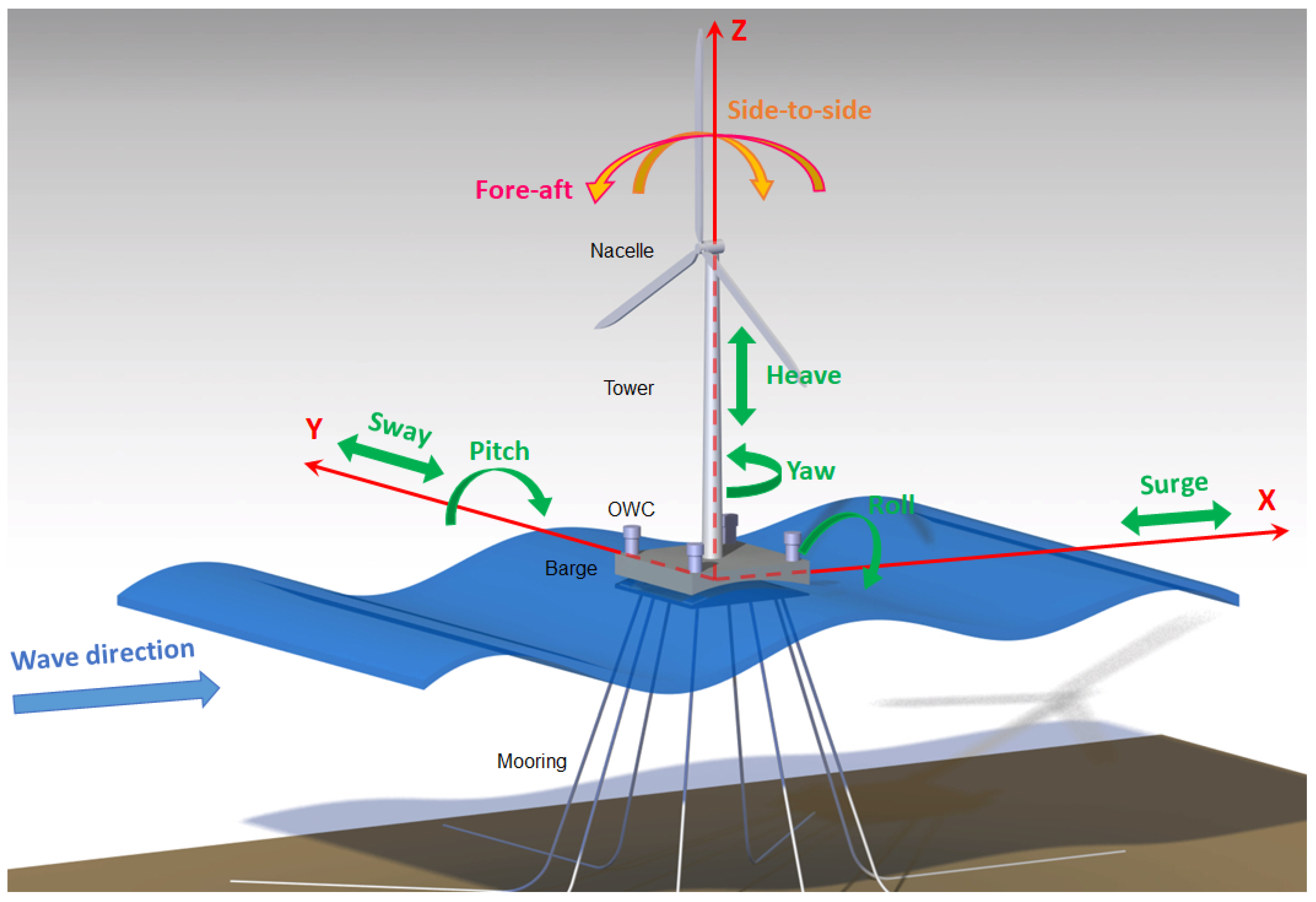
4) is the generalized outside force applying to the system, including the aerodynamic load on the blades and the nacelle, hydrodynamic force on the platform, elastic and servo forces. This study does not consider wind and servo forces for yaw, pitch and generator control of the wind turbine. Hence, the total number of DOFs evaluated is eight consisting of surge, sway, heave, roll, pitch, yaw, fore-aft and side-to-side displacements, as shown in
Figure 1. The origin of the coordinate system is at still water line.
The system linear equations of motion in frequency domain is written as:
where
,
and
are inertia, damping and stiffness matrices, respectively.
and
represent the hydrodynamic force and viscous drag of the waves on the platform and the load induced by the Power-Take-Off (PTO) equipment respectively.
q from Equation (
5) is defined as:
The inertia matrix of the FOWT system is defined by Equation (
7) as:
where
and
are platform and tower mass matrices, respectively. Platform mass matrix is expressed as:
and the diagonal terms are defined as follows:
where
,
and
are inertial mass in three translational directions, which are equal.
,
and
are the inertial mass in three rotational directions.
,
and
are the position of the structure’s center of mass in the still water level coordinates. The mass matrix of the tower is
matrix containing elements coupling the tower bending with the tower rigid heave motion.
is the platform’s added mass calculated by WAMIT from the panel radiation program and it is frequency-dependent.
Equation (
6) shows the modes of the system with the six first ones for the platform motions and the two last ones for the tower bending displacements.
The stiffness matrix
is defined as:
where
is the platform’ hydrostatic restoring matrix obtained by WAMIT and
contains the mooring lines spring stiffness coefficients and
is the tower stiffness matrix.
The damping matrix is given by:
where
is the floating platform’s damping matrix.
and
are damping matrix of the flexible tower and the nonlinear viscous drag on the platform, respectively.
is the effect of the PTO on the overall dynamics represented as the external force. Assuming that the internal free surface behaves like a piston, the pressure is uniform inside the chamber [
28]. Therefore, the external force is defined as:
where
p is the pressure drop across the turbine and
S is the internal free surface area. Considering the air as an ideal gas and the air compression and decompression as an isentropic process, the time-dependent air density can be given by:
where
and
are the density and pressure representing the state of the chamber at rest and
describes the heat capacity ratio of air. After linearization of the time derivative of Equation (
15), the following equation is obtained:
The linearized mass flow inside the turbine can be given by [
37]:
where
V is the air volume through the chamber and
is the air volume in the chamber in an undisturbed condition.
Using non-dimensional turbo-machinery nomenclature, a Wells turbine of diameter
D and rotational velocity
N is characterized by a linear relation between the pressure and flow coefficients:
where the pressure and flow coefficients are described as:
The pressure drop is considered proportional to the flow rate. Hence, nondimensionalization is used and the linear relation is defined by:
where the pressure and flow coefficients are expressed as:
where
g is gravitational acceleration value. Therefore, introducing Equations (
21)–(
23) into Equation (
17), the mass flow inside the turbine is described as:
By combining Equations (
17) and (
24), the pressure complex amplitude can be expressed as:
where
is the complex amplitude of the air volume oscillation and the constants
and
are given by:
According to Equations (
14) and (
25), the PTO force is described as:
where
is the complex amplitude of the relative displacement. According to the aforementioned Equation (
25), the PTO damping and stiffness coefficients are as follows:
and
Finally, the system of motion equations for the 8-DOF of the FOWT, given by Equation (
5), in the frequency domain, may be rewritten as:
The term on the right-hand side of Equation (
31) is described as:
where
is the viscous force and
is the hydrodynamic force of the waves on the platform.
can be obtained from the panel diffraction program of WAMIT.
3. Methodology
This section presents and explains the materials and methods used to achieve this research work. The structure of this section is organized as follows.
Section 3.1 introduces the modeling and design of the newly proposed 4OWC-based barge platform structure. In
Section 3.2, advanced computations were carried out with the designed platform to calculate the structure’s added mass, damping matrix, hydrostatic matrix and hydrodynamic forces.
Section 3.3 incorporates the obtained parameters into the aforementioned model equations to perform numerous simulations. In
Section 3.4, the system is analyzed using RAO indicators to evaluate the behaviour of the system in various frequencies.
3.1. 4OWC-Based Platform Design
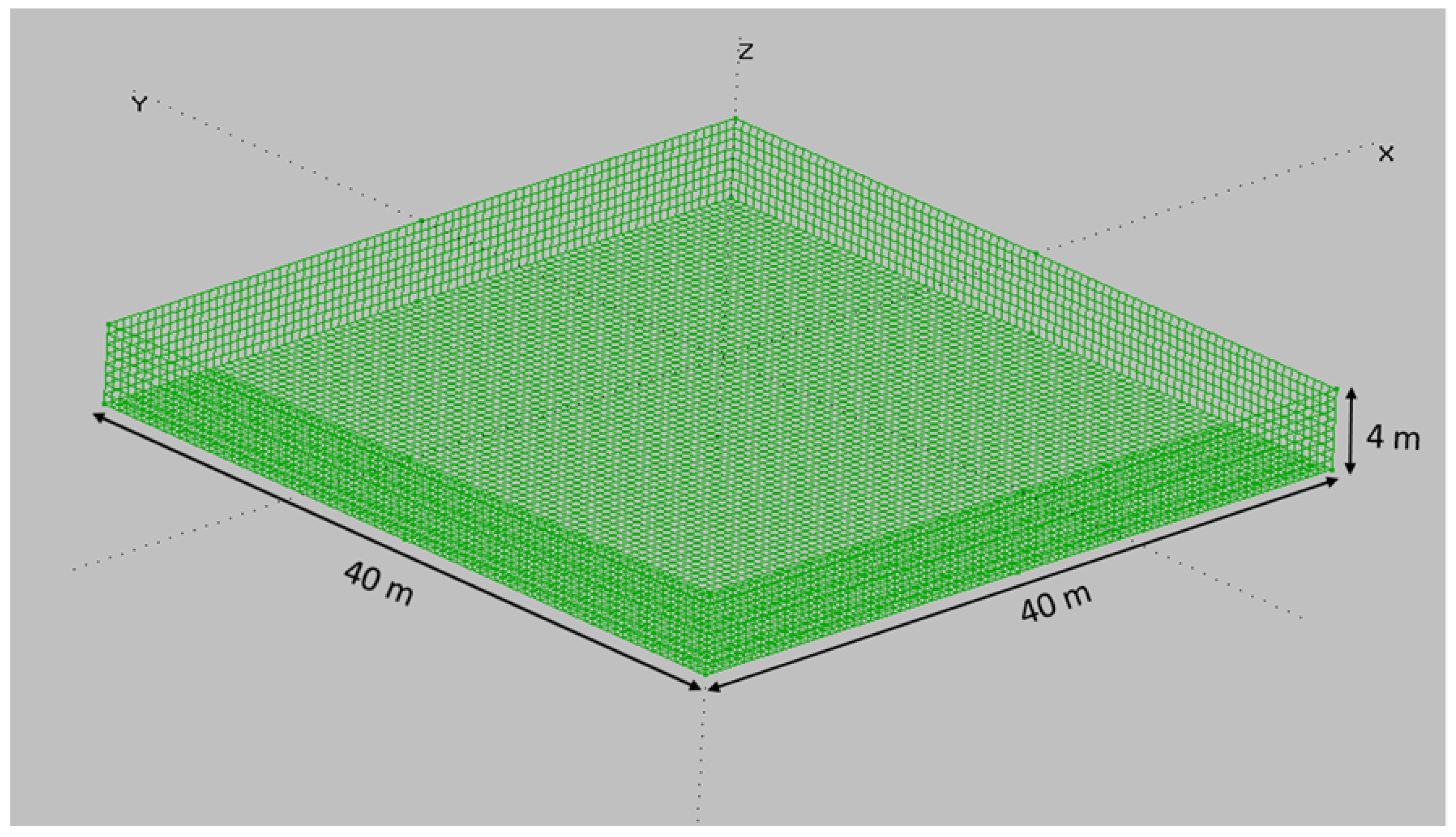
MultiSurf is used to design the geometry of the platforms. Two different platforms with varied features have been compared. The first platform is a standard barge platform which can be seen in
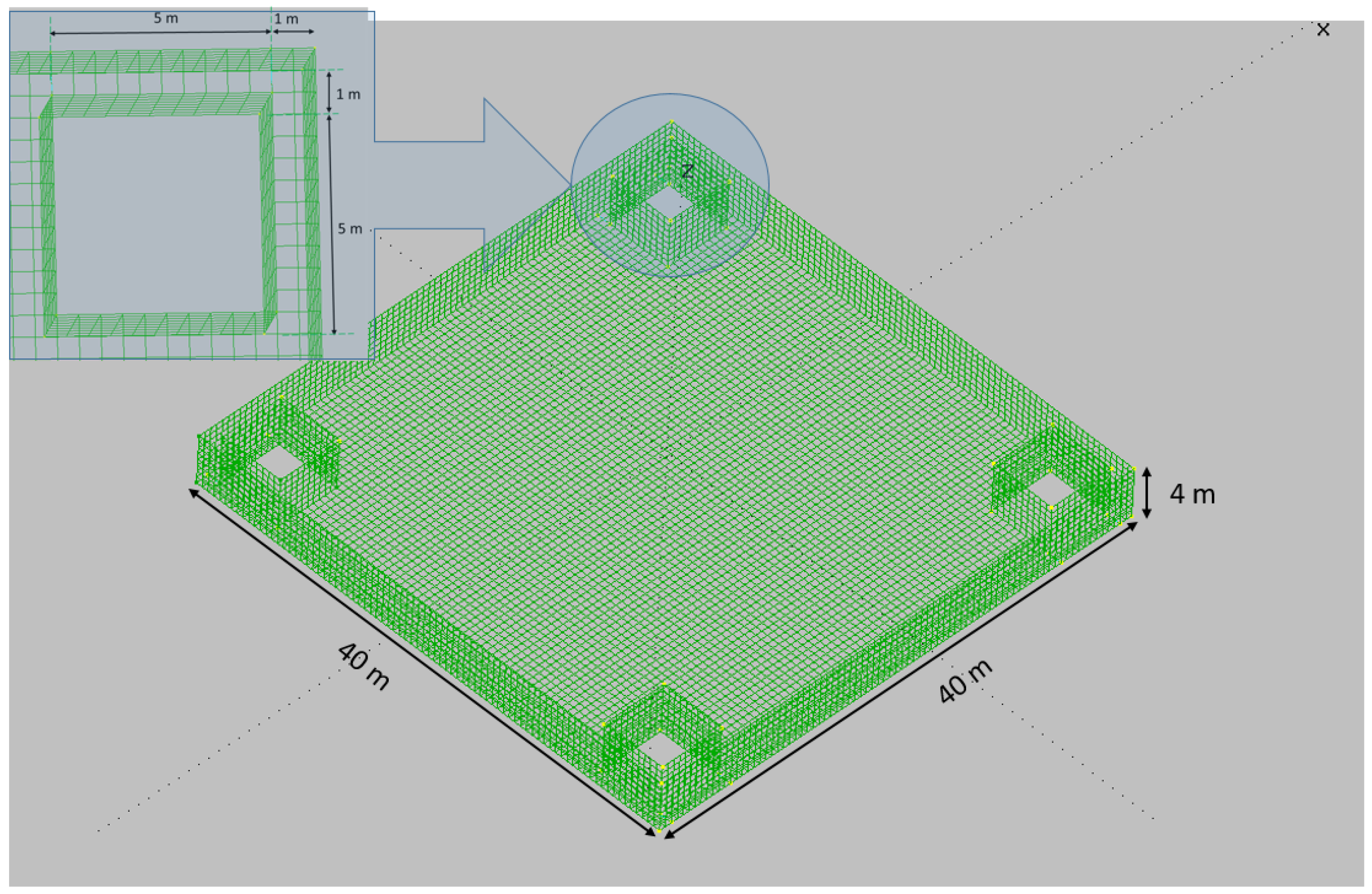
Figure 2 while the second one belongs to a barge platform with consideration of four OWCs at the corners showed in
Figure 3.
Consistent with linear theory, only the wetted portion of the body is meshed in its undisplaced position [
34] via MultiSurf. In this study, the calculated draft is 4 m. The standard barge platform is modeled with 2240 rectangular panels within a quarter of the body. The barge with two geometric planes of symmetry with respect to
x-axis and
y-axis is modeled.
The second platform with 9840 total rectangular panels is modeled and the OWCs have a distance of one meter from the sides of the platform with the dimensions 5 m × 5 m × 10 m.
Table 1 details the characteristics of the barge platform and the 4OWC platform.
3.2. Advanced Hydrostatic and Hydrodynamic Computations
Panel method WAMIT was used to get the matrices
,
,
and
described in
Section 2. This advanced computational tool provides analysis of interaction between wave inputs and floating offshore platforms. WAMIT calculates the hydrodynamics loads resulted from water pressure on the wetted surfaces and can be linked to MultiSurf to use the geometric floating model.
The relationship between the added mass and damping coefficients is defined by:
Thus, the normalized added mass and damping coefficients are:
where
L is the length scale,
for
,
for
or
and
for
.
All hydrostatic data can be expressed in the form of surface integrals over the mean body wetted surface
, by virtue of Gauss’ divergence theorem. Volume is defined as:
Coordinates of center of buoyancy are given by:
Matrix of hydrostatic and gravitational restoring coefficients are defined as:
where
are the coordinates of the center of gravity and
.
3.3. Proposed Platform and Tower Integration
FAST (Fatigue, Aerodynamics, Structures, and Turbulence) joins aerodynamics, hydrodynamics models for offshore structures, control and electrical system (servo) dynamics models, and structural (elastic) dynamics models to enable coupled nonlinear aero-hydro-servo-elastic simulation in the time domain. The FAST tool enables the analysis of a range of wind turbine configurations, including two- or three-blade horizontal-axis rotor, pitch or stall regulation, rigid or teetering hub, upwind or downwind rotor, and lattice or tubular tower.
The offshore dynamic responses has been incorporated within FAST implementing nonlinear equations of motion for 5-MW offshore wind turbine. The properties of the offshore turbine are provided in
Table 2.
3.4. 4OWC-Based Platform’s Motions Evaluation
To evaluate the response motions of a floating object, obtaining a generic procedure to have an input-output system is significant. A floating platform response can be predicted from wave inputs with different frequencies. To achieve that goal, analysis of Response Amplitude Operators (RAO) plays an important role. In design of FOWTs, the hydrodynamic loads, aerodynamics, structural dynamics (including blade and tower flexibility), and controller dynamics should be taken into account because they have an important effect on the whole system and its motion responses [
39].
The nonlinear dynamics of the FOWT excited by hydrodynamic and aerodynamic loads requires a highly advanced tool which makes the RAOs computation accurate, hence FAST v8 has been used. Such a system is excited by white-noise wave input in time-domain for obtaining RAOs.
A specific procedure has been followed to plot the RAOs for the rotational and transnational motions as system’s outputs. First, using the geometric data from MultiSurf, WAMIT calculations are performed for introducing added-mass, damping matrices, hydrostatics coefficients and hydrodynamic loads to be taken into account for the equations of motion. Then the equations are employed in FAST to achieve system’s outputs. Calculation of RAOs for every system’s mode via the auto-spectral density of the input (wave elevation) and the cross-spectral density of the input/output (system responses) is conducted. Aforementioned procedure should be performed for
M times with different seeds for production of white noises as system’s wave input. Next the first seconds from each computation is removed for transient effects. Finally, the average sets are calculated. The reason of calculating the average sets is that averaging over different realizations smooths the spectrum. The peaks and drops disappear and the histogram become concentrated around its mean value [
40]. Also, it reduces the leakage effects with a lower noise sensitivity.
The RAO calculated in the procedure is defined as:
where
and
are the cross-spectral and auto-spectral densities of the input
and the output
, in the frequency domain, respectively.
and
can be defined as follows:
with
the Fast Fourier Transform (FFT) spectrum of segment
s.
M is the number of simulations of the procedure and
r is the random noise sequence.
is the complex conjugate of
X.
Random noise excitations are used for obtaining RAOs because their use is very popular in practical applications and also it seems much accurate to generate and use random noise excitations than periodic signals.
The Results of using the above procedure in order to plot the RAOs are shown in the following
Section 4. Besides, different frequencies are chosen to demonstrate the performance of the platforms in various sea states.
4. Results and Discussion
The wind turbine selected in this article is 5-MW floating wind turbine, which can be found in [
38]. This floating wind turbine is installed on a barge platform. J. Jonkman et al. proposed a simple barge with a moonpool covered by a lid [
34] and this moonpool can be used for installation of an OWC.
Our proposed model is a platform with four OWCs located symmetrically at each corner that is compared with a standard barge platform without any OWCs.
To have maximum energy production by FOWTs, we need to minimize the oscillations in the platform created by waves [
21]. In this section, figures show how the new model can have significant impact on the reduction of oscillations in translational and rotational modes under specific sea states. In this work, rotational modes including roll, pitch and yaw are more important since finally decrease the vibrations on two modes of the FOWT consisting of fore-aft and side-to-side displacements is needed.
In this section, first the RAOs’ results are indicated in different sea states and then platforms displacements at specific frequencies based on RAO’s curves are plotted.
4.1. Response Amplitude Operators
To assess the platforms’ motions, RAOs can be analyzed and evaluated. In fact, RAOs for system’s modes give the ability to decide which platform has the better performance under varying sea states.
In the present study, the procedure in
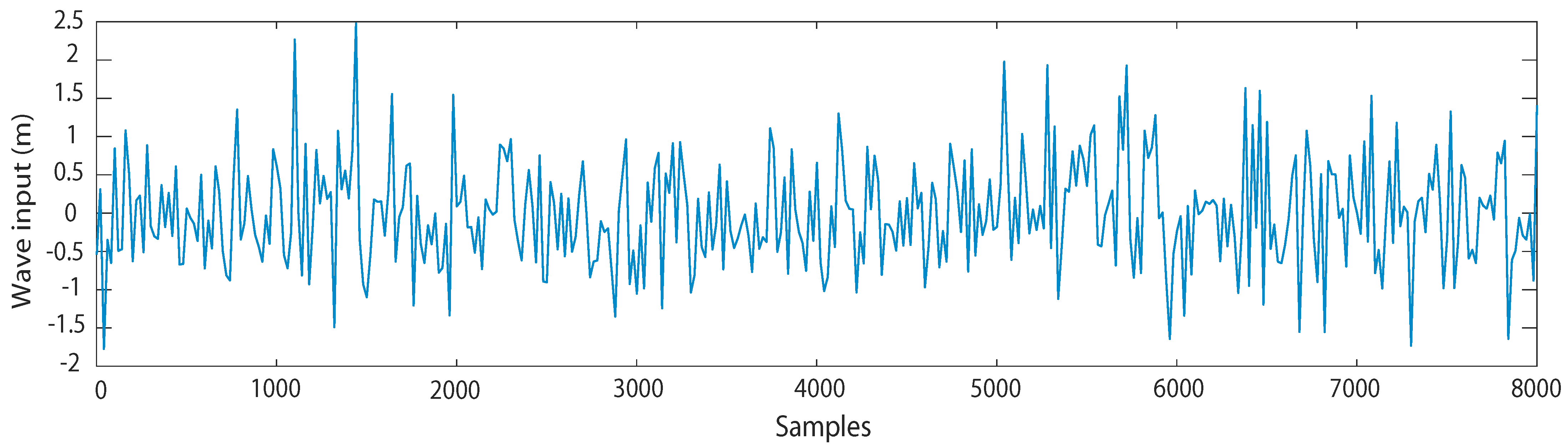
Section 3.4 and following numerical conditions for plotting RAOs are considered. Simulation time for every computation is 8000 s and 2000 s were removed from each computation for transient effects. Wave inputs have a height of 2 m with random white-noise to ensure the linear wave theory. Six computations are conducted for averaging (
).
Additionally, some environmental conditions are assumed. First of all, heading waves of zero degree and still air condition is considered. Nonlinearities caused by the flexible tower, hydrodynamic loads, viscous effect and mooring lines are taken into account. Also, no servo control such as pitch, yaw and generator control is applied.
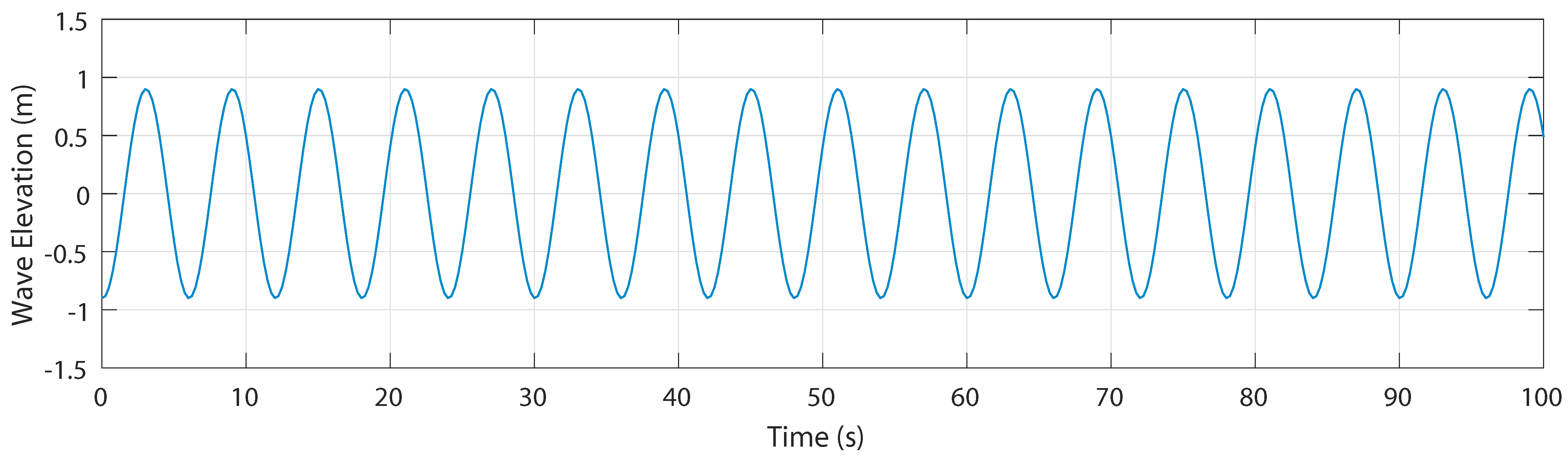
Figure 4 shows the wave input for one computation. For other computations, different seeds are considered but the wave heights are the same.
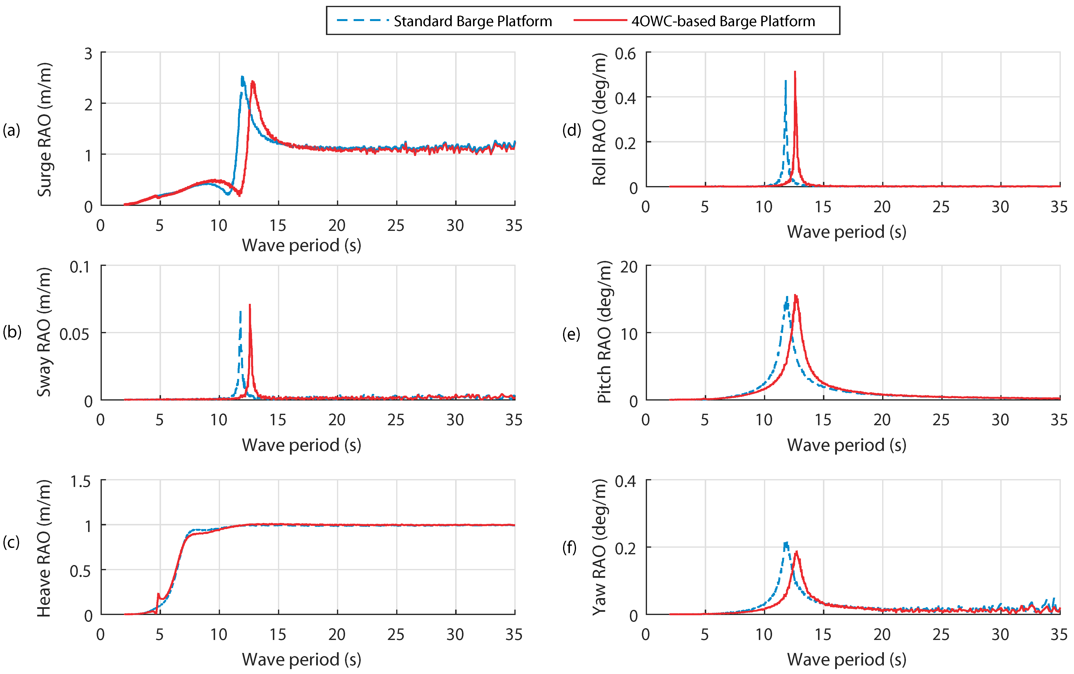
In the present work, RAOs for six modes are plotted.
Figure 5a–f show the RAOs for surge, sway, heave, roll, pitch and yaw. RAOs are plotted for the period range of 2–35 s (0.0028–0.5 Hz). Blue dash and red curves represent the RAOs for the standard barge platform and platform with four OWCs, respectively.
Because of the wave heading along surge direction and absence of the wind force, the excitations even at the resonance frequencies of sway, roll and yaw are considerably less than other states RAO, as shown in
Figure 5b,d,f. Hence, small oscillations are expected for these modes.
There is a shift in period between the two platforms, shown in
Figure 5a. From period 2 s to 7.5 s and 15 s to 35 s, RAOs are almost the same and it is expected that both platforms move similarly in surge. Surge resonance frequencies occur at 0.084 Hz (11.9 s) and 0.078 Hz (12.8 s) for the standard barge and 4OWC-based platforms, respectively.
Figure 5c shows the heave RAO (HRAO). It can be noticed that RAOs curves for both platforms are almost identical excluding from period 7.1 s to 10.3 s which HRAO for the standard barge platform is higher than that of the platform with four OWCs. Additionally, the curves indicate that the HRAOs follow the wave inputs for periods larger than 15 s which means that the heave output and wave input are similar.
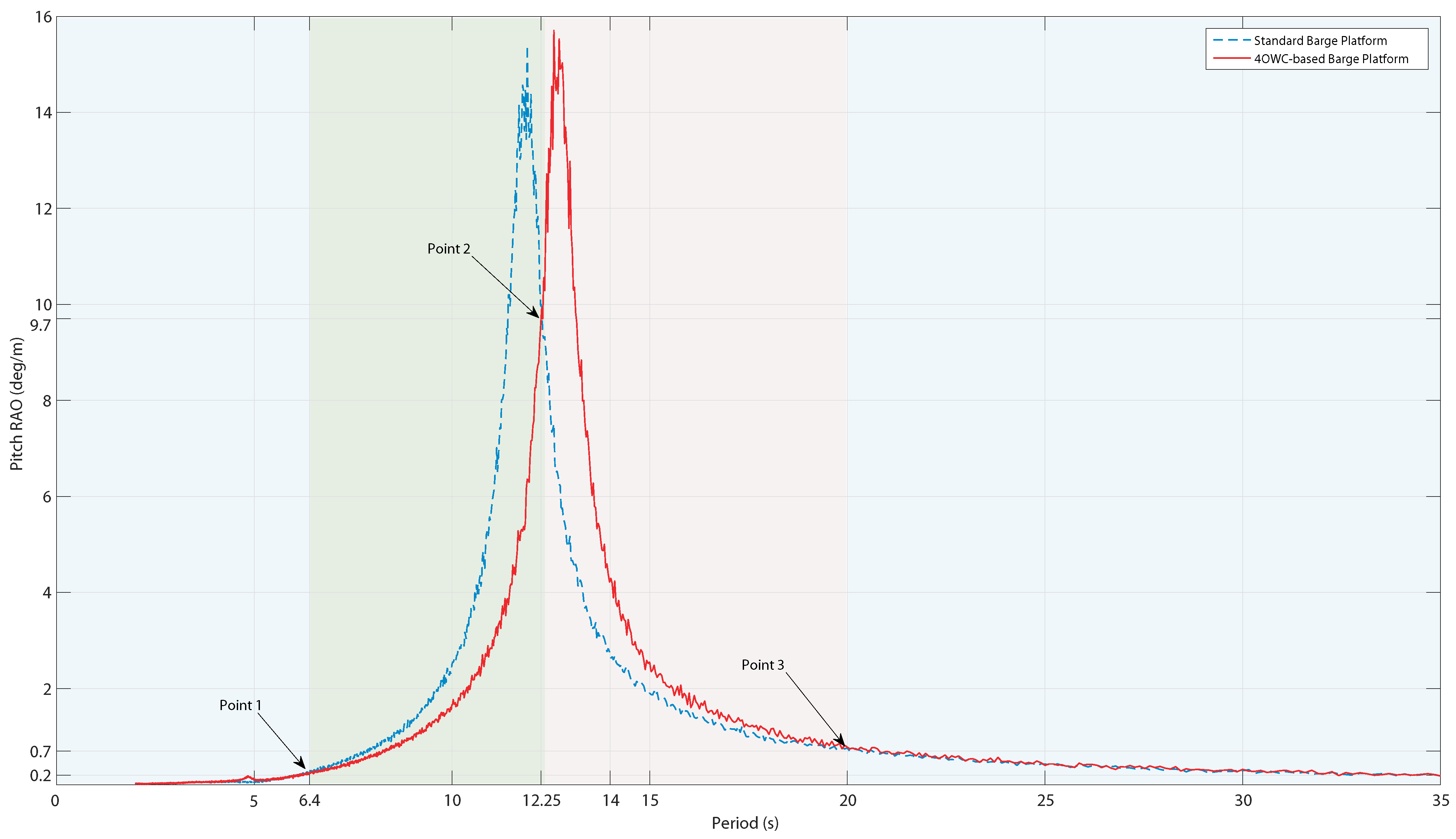
Figure 5e indicates the most significant spectrum, in this study, that is pitch because of the importance of angle reduction in rotational modes rather than the transnational modes for getting the maximum energy from wind. The RAO for this mode is illustrated individually in
Figure 6.
Through analyzing the Pitch RAO (PRAO), the platforms’ performance under different sea states has been carried out. It is noticeable that both platforms start pitching from period 2 s and then the platforms’ pitch increase to peak at their resonance periods at 11.9 s and 12.71 s for the standard barge platform and 4OWC-based barge platform, respectively. Then the platforms’ pitch decrease for longer-period waves to reach to near zero.
Figure 6 is divided into four regions, described as follows:
The first region is from 2 s to 6.4 s (point 1) where both curves are almost identical. It is expected that the platforms’ pitch have the same angle and minor oscillations in these periods. One period is chosen in this region for more detailed analysis after doing simulation in FAST (first chosen period s).
The second region highlighted in green is from 6.4 s (point 1) to 12.25 s (point 2). In this zone, PRAO for the proposed platform is lower than the standard barge. It means that the pitch oscillation for the proposed platform is less than that of the standard barge. The second chosen period in this zone is 10 s.
The third region is from 12.25 s (point 2) to 20 s (point 3) highlighted in red. In this region, the reaction of the system to waves input is different and PRAO for our proposed platform is higher than a standard barge. Therefore, it is predictable to have less oscillation with the standard barge platform, compared to the proposed one. T = 14 s is considered in this zone for more analysis.
The last region from 20 s (point 3) to 35 s is like the first region because two curves are identical. The considered period is the period of 30 s in this zone.
Briefly, Simulation results for more detailed analysis are discussed in the next subsection for four periods (T = 6 s, 10 s, 14 s and 30 s).
4.2. Performance Analysis in Different Sea Conditions
By analyzing the RAOs for six modes of the system from last subsection, four periods have been chosen for obtaining more details of the system’s behaviour in this subsection.
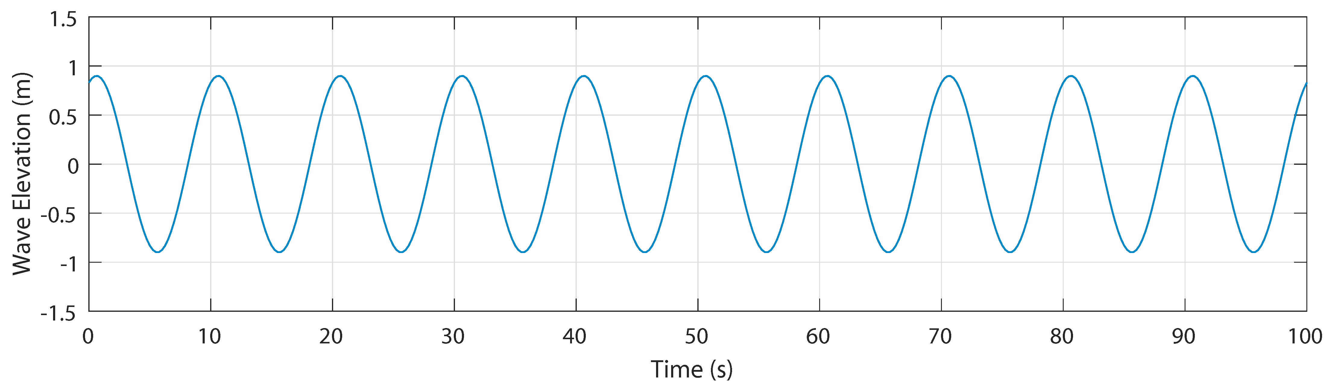
To investigate the performance of the proposed platform in comparison with the standard barge platform, by considering still winds and regular waves with a zero direction and a wave height of 0.9 m and tanking into consideration the aforementioned environmental conditions.
4.2.1. First Evaluated Period
Figure 7 shows the regular wave elevation with the amplitude of 0.9 m and period of 6 s.
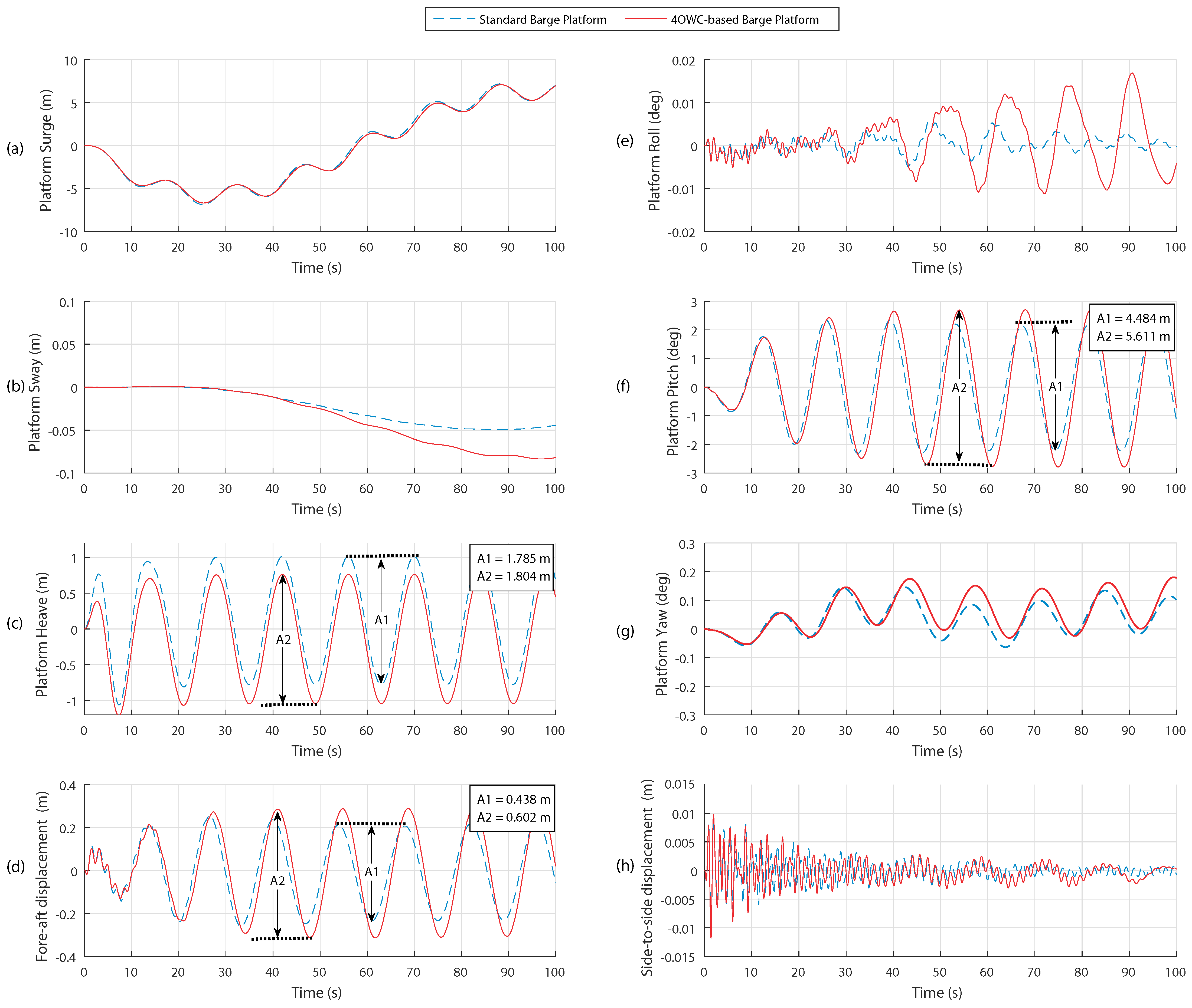
From the RAOs for sway, roll and yaw illustrated in
Figure 5b,d,f, we expect to see slight oscillations in the forenamed modes, as shown in
Figure 8b,e,g. Also, as a result of those slight motions in lateral modes, side-to-side tower top moves slightly on the platforms, represented in
Figure 8h.
At the period of 6 s,
Figure 5a illustrates that the Surge RAO (SRAO) for the standard barge is somewhat higher than that of the introduced platform. It is in a good agreement with the platform surge motions, shown in
Figure 8a where the domain of oscillation for the standard barge is slightly higher than the platform with OWCs.
Figure 5c indicates that the HRAO spectrum for the standard barge is slightly lower than that of the proposed platform at period 6 s. It is demonstrated in
Figure 8c that the standard barge oscillates less than the platform with OWCs.
According to the PRAO at period 6 s (
Figure 6), the platforms have small oscillations in pitch. In addition, PRAO curves for the platforms are identical at that period which can be verified by
Figure 8f. This Figure shows that slight pitch motions for both platforms are identical after transient response.
Finally, as a result of the slight platforms’ pitch motion, fore-aft tower top follows the analogous behaviour, illustrated in
Figure 8d.
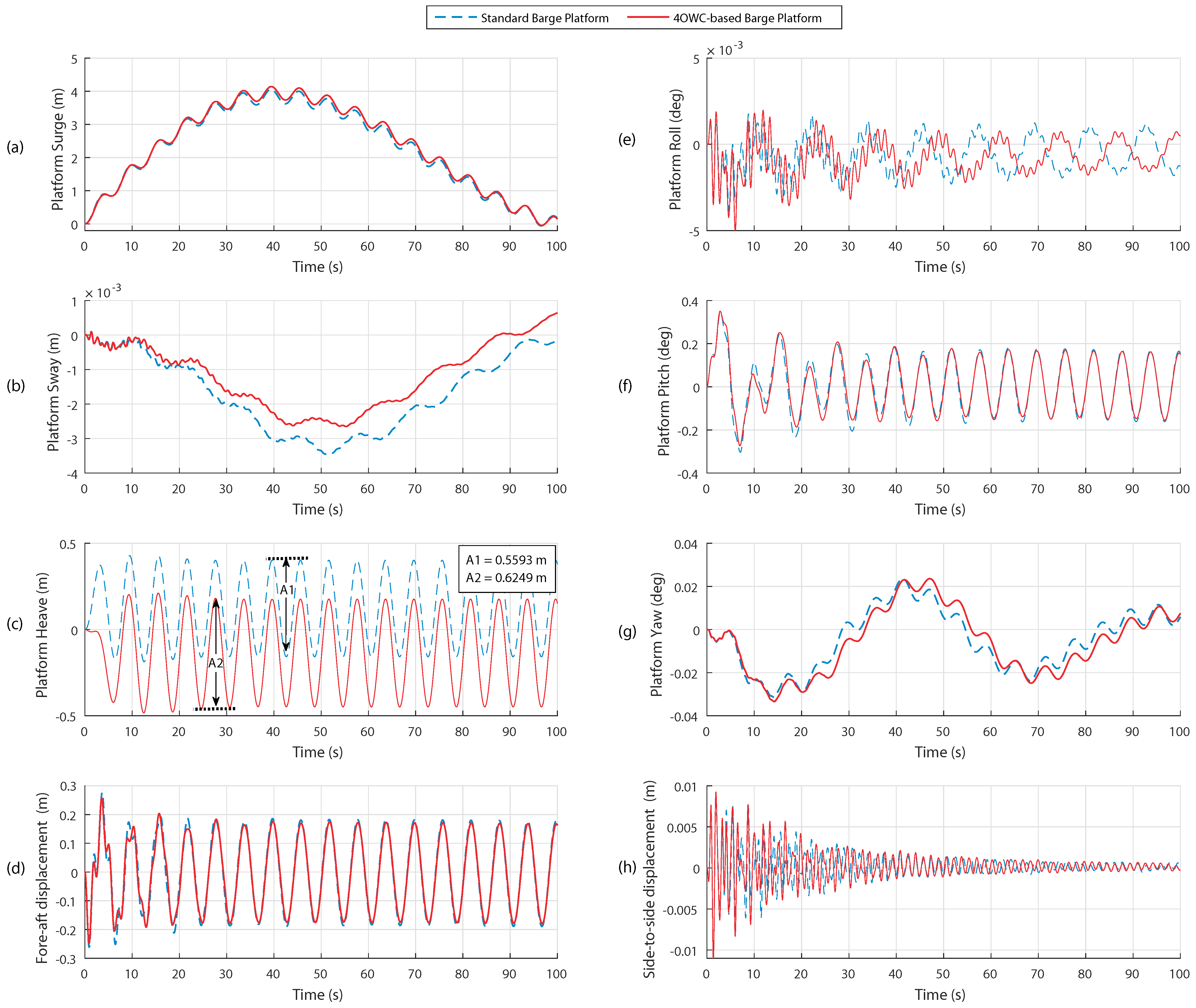
4.2.2. Second Evaluated Period
The regular wave input with the period of 10 s and amplitude of 0.9 m can be seen in
Figure 9 for the second region.
With consideration of the RAOs for sway, roll and yaw, shown in
Figure 5b,d,f, it can be realized that no vibrations occur in those modes at period 10 s. Also, side-to-side tower top mode does not excite because of no excitation in lateral modes. This can be confirmed in
Figure 10b,e,g,h.
The SRAO at the period of 10 s for the standard barge is lower than that of the proposed platform, illustrated in
Figure 5a. It agrees with the platform surge motions, which after transient response, the domain of oscillation for the standard barge is lower than the second one, shown in
Figure 10a.
Figure 5c indicates that the HRAO for the standard barge is higher than for the proposed platform with OWCs at period 10 s. It is shown in
Figure 10c that the proposed platform oscillates less than the standard barge. The domains of oscillation are 1.72 m and 1.69 m for the standard barge and proposed platform respectively.
The period of 10 s was chosen from green region, represented in
Figure 6. We expect to see less pitch oscillation in the proposed platform than in the standard barge since the PRAO spectrum for the 4OWC-based barge is lower than the standard barge in the highlighted green zone. As it can be seen in
Figure 10f after transient response, the proposed platform oscillates less than another one by 30.1 percent which shows the better performance and capability of the introduced platform in this period as well as the green zone.
Moreover, that pitch reduction has an impact on fore-aft tower top displacement. In this mode, the platform with OWCs oscillates less than the standard barge by 25.13 percent as illustrated in
Figure 10d.
4.2.3. Third Evaluated Period
Figure 11 indicates a regular wave with the chosen period of 14 s and the amplitude of 0.9 s from the third region.
Because of the wave direction, the lateral modes are not excited for different frequencies. This fact can be noticed in the RAOs shown in
Figure 5b,d,f. At the period of 14 s, the Platforms’ sway, roll and yaw have quite minor oscillations illustrated in
Figure 12b,e,g. As a result of those minor oscillations of the platforms, side-to-side tower top oscillates slightly, illustrated in
Figure 12h.
It can be observed in
Figure 5a that SRAO for the standard barge is slightly lower than the proposed platform. Hence, a slight lower oscillation in the standard barge compared to the second platform is expected. This lower vibration is shown in
Figure 12a.
Through analysing the HRAO in
Figure 5c, the HRAO for the standard barge is slightly lower than that of the proposed platform. It can be seen in
Figure 12c that the proposed platform oscillates for 1.8 m and follows the wave input well while the standard barge oscillates for 1.78 m, slightly less than 4OWC-based platform.
PRAO at period 14 s from the third zone is considered and represented in
Figure 6. We expect to see more pitch oscillation in the proposed platform than the standard barge since the PRAO spectrum for the 4OWC-based barge is higher than the standard barge in this zone. As it can be seen in
Figure 12f after transient response, the proposed platform oscillates more than another one by 20 percent at period 14 s which shows that the standard barge has a better performance at this period as well as the third region.
Additionally, the influence of those pitch angles is noticeable on fore-aft tower top displacement. In this mode, the platform with OWCs oscillates more than the standard barge by 27 percent as indicated in
Figure 12d.
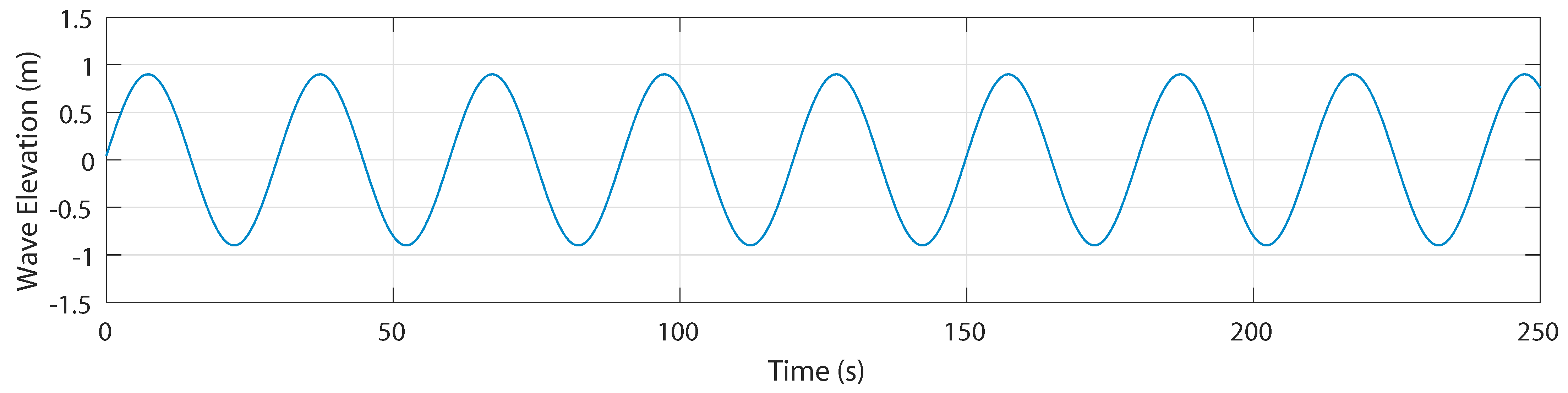
4.2.4. Fourth Evaluated Period
The considered wave elevation input for this zone is with period 30 s and amplitude 0.9 m as shown in
Figure 13.
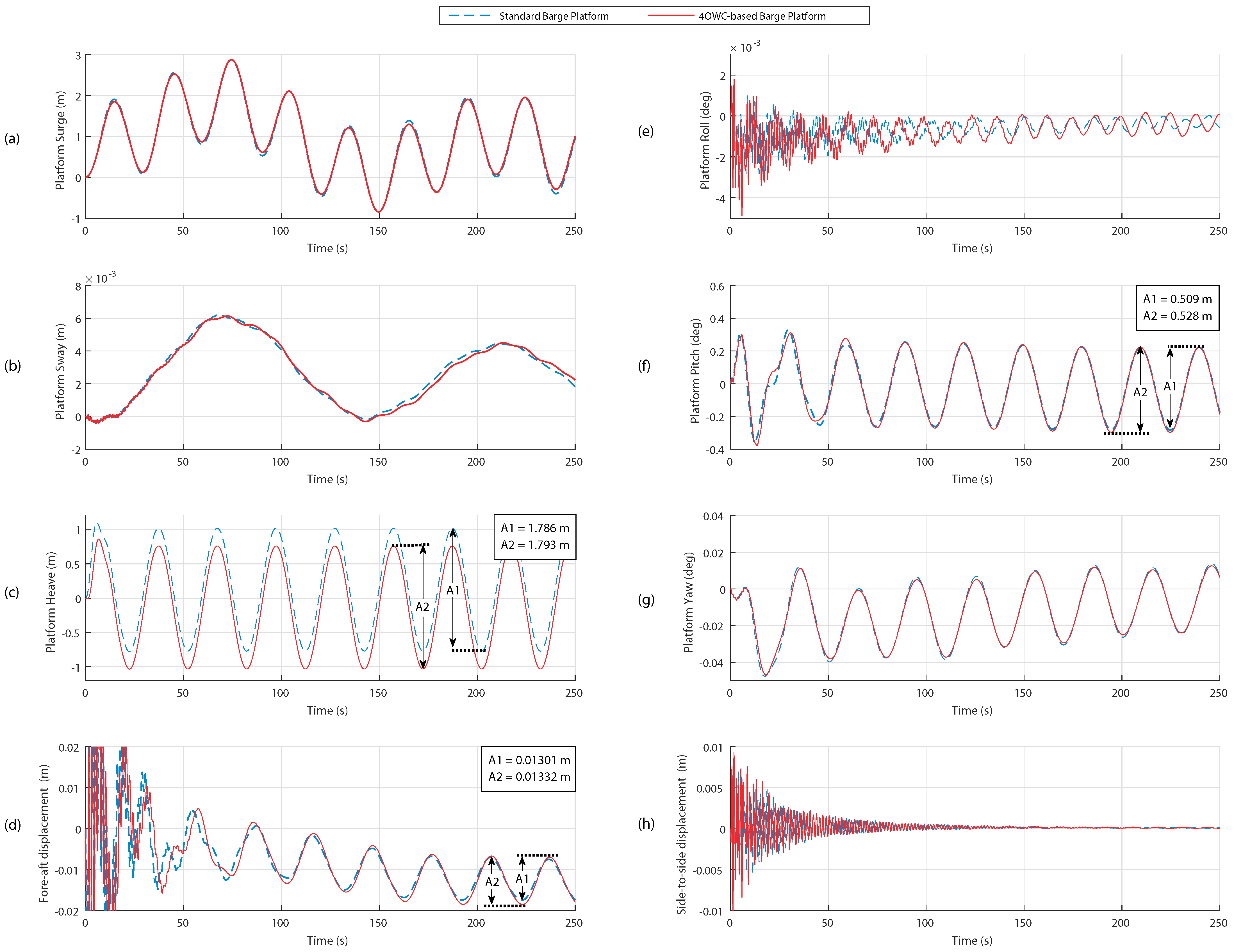
The heading wave direction of zero degree causes the lateral modes of sway, roll, yaw and side-to side tower top are not excited at period 30 s as illustrated in
Figure 14b,e,g,h. This is what we expected to happen from the modes RAOs in
Figure 5b,d,f.
Since the SRAOs from
Figure 5a at the period of 30 s are almost identical, the same oscillations in surge are expected for both platforms as shown in
Figure 14a. This figure shows that both platforms oscillate in surge for 1.9 m.
For the long-wave periods, HRAOs for both platforms are identical and unit, indicated in
Figure 5c. Therefore, It is predicted that both platforms have the same behavior in heave and follow the wave elevations as can be observed in
Figure 14c.
Figure 6 represents the PRAOs showing the minor values and identical curves for both platforms in long-wave periods. The expectation from the PRAOs is that both platforms have the same slight oscillations in pitch at period 30 s, shown in
Figure 14f. As it was stated, this region is like the first one in terms of pitch motion and both platforms have the same performance.
Besides, the influence of the pitch angles is notable on fore-aft tower top displacement, shown in
Figure 14d. Fore-aft displacements for both platforms are about 13 mm.
5. Conclusions
In this article, a novel design introduced for a barge platform. In this model, four OWCs were used in the standard barge platform to alleviate the platform oscillations especially in its rotational modes and tower top displacements. To evaluate the performance of our introduced platform, first the RAOs were depicted for different modes to show the behaviour of the system in frequencies. Then four specific periods were chosen for more evaluations.
The system’s behaviour was analyzed for all the modes in periods. The reduction of pitch and fore-aft top tower displacements are the most important objectives in this study because they can lead to capture maximum wind supply.
The results showed that the proposed model for the pitch and fore-aft tower top modes could efficiently decrease the oscillations occurring in the platform by regular waves with periods 6.4 s–12.25 s (green zone). However, from the period of 12.25 s through 20 s (red zone), the standard barge platform had a better performance. For the rest of the periods (blue zone), differences between two platforms were not recognizable.
Four periods were evaluated in the last subsections. We showed that there are very small oscillations in sway, roll, yaw and side-to-side tower top displacements for both platforms in different periods. For the surge mode, the platforms oscillate the same in the periods of 6 s and 30 s while the standard barge moves slightly less than our proposed platform in periods 10 s and 14 s. Analysis of the heave state for all the evaluated periods showed that the platforms oscillate almost similarly with very minor differences. Finally, the evaluations of the platforms indicated that both have the same behaviour in pitch and fore-aft tower top motions. It was clarified that for those modes, both platforms have the same oscillations in short-wave and long-wave periods whereas our proposed platform have a better performance in the period of 10 s and a worse performance in the period of 14 s.
The present work and the performance analysis findings encourage the future implementation of a specific control strategy over the 4OWC-based barge platform. This will allow us to adequately govern the capture chamber air valve opening/closing for resonance frequencies within critical ranges so as to avoid undesired high oscillations that appear in traditional barge platforms.


