Article

Fault-Tolerance by Resilient State Transition for Collaborative Cyber-Physical Systems

Department of Computer Science, Chungbuk National University, Cheongju 28644, Korea
*
Author to whom correspondence should be addressed.
Mathematics 2021, 9(22), 2851; https://doi.org/10.3390/math9222851
Submission received: 29 September 2021 / Revised: 4 November 2021 / Accepted: 7 November 2021 / Published: 10 November 2021

Abstract

:
Collaborative Cyber-Physical Systems (CCPS) are systems where several individual cyber-physical systems collaborate to perform a single task. The safety of a single Cyber-Physical System (CPS) can be achieved by applying a safety mechanism and following standard processes defined in ISO 26262 and IEC 61508. However, due to heterogeneity, complexity, variability, independence, self-adaptation, and dynamic nature, functional operations for CCPS can threaten system safety. In contrast to fail-safe systems, where, for instance, the system leads to a safe state when an actuator shuts down due to a fault, the system has to be fail-operational in autonomous driving cases, i.e., a shutdown of a platooning member vehicle during operation on the road is unacceptable. Instead, the vehicle should continue its operation with degraded performance until a safe state is reached or returned to its original state in case of temporal faults. Thus, this paper proposes an approach that considers the resilient behavior of collaborative systems to achieve the fail-operational goal in autonomous platooning systems. First, we extended the state transition diagram and introduced additional elements such as failures, mitigation strategies, and safe exit to achieve resilience in autonomous platooning systems. The extended state transition diagram is called the Resilient State Transition Diagram (R-STD). Second, an autonomous platooning system’s perception, communication, and ego-motion failures are modeled using the proposed R-STD to check its effectiveness. Third, VENTOS simulator is used to verify the resulting resilient transitions of R-STD in a simulation environment. Results show that a resilient state transition approach achieves the fail-operational goal in the autonomous platooning system.

1. Introduction

Collaborative Cyber-Physical Systems (CCPS) are systems where many individual CPSs form a coalition to achieve a specific task [1,2]. CCPS are gradually becoming common in several domains. For instance, in smart grids, a virtual power plant comprises of multiple distributed energy resources (electric vehicles, etc.) that jointly provide electricity during peak hours [3]. In smart factories, the transportation robots form fleets that coordinate to fulfill material requests [4]. CCPS are designed to operate in a highly dynamic context and deal with various uncertainties that may arise at runtime. The uncertainties challenge the system’s ability to meet its requirements, resulting in the system being unable to achieve its goal. In some situations, it may even lead to a safety hazard for the human being. For example, suppose the leader vehicle in autonomous platoon driving does not recognize the obstacles due to fog that may trigger unexpected behavior of the platooning vehicle. In this case, the short distance between platooning vehicles may lead to a collision. Hence, in the platooning system, the inter-vehicle distance is required to be large enough to allow a vehicle to react to the sudden braking of a preceding vehicle without collision risk. Due to the heterogeneity of member vehicles, the reaction time merely depends on the quality of sensors on board and inter-vehicle communication capabilities. Therefore, the safety of CCPS, such as autonomous platooning is critical. Unlike fail-safe systems, e.g., the shutdown of one of the system’s actuators or sensors may lead to a safe state. However, in autonomous platooning driving, the member vehicles must be safe-operational, meaning that the shutdown of a platoon member driving on the highway is not acceptable. Therefore, such hazardous situations should be mitigated, and safety protocols must be followed even under extreme conditions.
The platoon driving system, a representative example of CCPS, is recently in the limelight due to several advantages, such as fuel efficiency and traffic congestion reduction. In the platooning system, several vehicles form a group and drive with a narrow distance to increase traffic flow and fuel reduction. The narrow distance can be obtained by collecting real-time data about the preceding vehicles in the platoon. This is possible by employing onboard sensors and wireless communication with each other using the Cooperative-Adaptive Cruise Control (C-ACC) technique [5]. One of the possible ways to achieve sustainable platoon driving under uncertainty is a Resilient State Transition (R-ST). The R-ST defines possible systematic steps of lower and lower acceptable operational modes of platooning vehicles and selects an appropriate mode in the presence of failures. Hence, the platooning system would maintain its operation as long as possible under the worst conditions. For instance, in the platooning system, a member vehicle can switch to Adaptive Cruise Control (ACC) mode from C-ACC mode, relying on onboard sensors to manage the distance with the vehicle in front in case of uncertainty.
The platooning system’s collaborative behavior makes designing resilient state transitions challenging because it is challenging to manage subsequent failure combinations [6]. Kaiser et al. [7] presented a canonical approach where authors defined, designed, implemented, and verified the degradation cascades for embedded systems. In addition, the authors modeled requirements as a tree structure and annotated them with target values. We can say from the results presented that the proposed systematic process could deal with increasing complexity in CCPS. However, a fail-operational scenario was not considered in their studies.
In this paper, we make the following contributions:
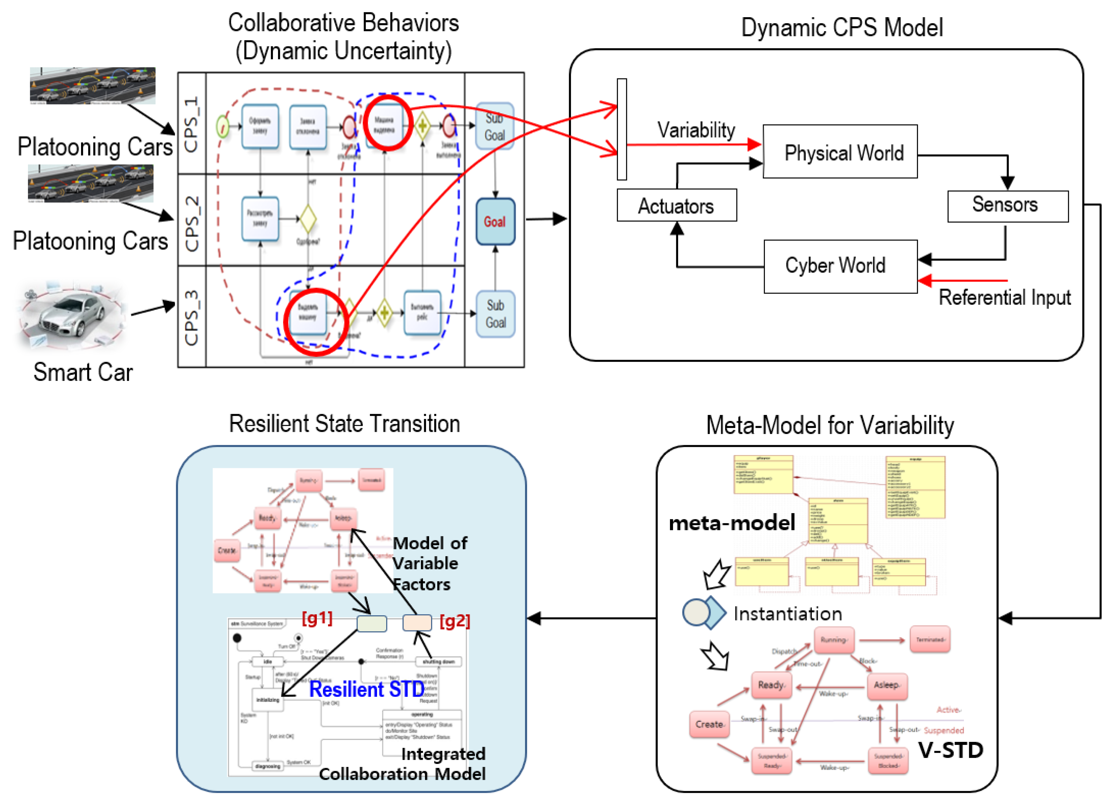
  • We present a Resilient State Transition Diagram (R-STD) to ensure fault tolerance in an autonomous platooning system. R-STD is an extended version of the state machine diagram. In R-STD, additional elements such as failures, mitigation strategies, and safe exit machines are introduced to achieve resilience in the safety-critical system (e.g., autonomous platooning system).
  • To validate our proposed approach, we present a case study on the autonomous platooning system. We modeled perception failures of the leader vehicle such as the failure caused by dense fog, communication failure, and ego-motion estimation failure using our proposed R-STD to see their effectiveness. Furthermore, VENTOS simulator [8] is used to verify the resulting resilient transitions of R-STD.
The rest of this paper is organized as follows. Section 2 provides related work; in Section 3, we present the concept of state transition diagram and R-STD. In Section 4, we explain our proposed approach. Section 5 presents our case study; Section 6 presents our case study simulation in VENTOS simulator; Section 7 concludes this paper.

2. Related Work

Designing a Cyber-Physical System (CPS) is challenging because they need higher reliability than a general-purpose system. Lin and Panahi [9] proposed a real-time service-oriented architecture to enhance predictability and sustainability in CPSs. The authors developed middleware that includes components to monitor the service process and identify the cause of uncertainties when they occur, and the system can reconfigure itself when necessary.
Zhang et al. [10,11] have proposed a conceptual taxonomy of uncertainty in CPSs, where the uncertainty of context, sensors, and knowledge can be translated under the uncertainty of the predictive model. The authors also presented a conceptual model for self-healing CPSs to enhance sustainability. These are considered to be an acceptable means to define uncertainty in UML at large. The authors argued that the conceptual model is based on the idea that uncertainty in the system is subjective, meaning that uncertainty depends on some actor’s state of belief and knowledge. According to the authors, belief is the main concept that can be subject to uncertainty. The type of uncertainty determines what is uncertain exactly in the system. However, resiliency is not discussed in the above research.
Hyun et al. [12] have presented a statistical verification framework known as StarPlateS for a platooning system. The proposed framework addresses uncertainties in a platooning system by implanting three modules; (a) a scenario generation module that generates random configurations and scenarios using the condition-based algorithm and addresses internal uncertainties, (b) a simulation module that implements a platooning system on generated configurations and scenarios using a VENTOS simulator, (c) a verification module applies a model checking algorithm to verify the rates of specific goals. The authors generated approximately two to four platoons of size, with two to six vehicles in their simulation.
Zarrouki et al. [13] have described a systematic design of degradation cascades for communication and sensor failures in a platooning system using the autonomous model car example “Velox.” The authors proposed a platoon of size two that drives with a short inter-vehicle distance on a single road lane. Both vehicles were supposed to synchronize their speed and sensor data based on vehicle-to-vehicle communication and onboard sensors. The platoon members can be vehicles from different manufacturers, e.g., cars, trucks, etc. For a platooning operation, each member of the platooning vehicle is supposed to have the capability to determine the distance to the preceding vehicle, measure its motion data, and adjust its safe distance between vehicles. The safety of inter-vehicle distance may depend on each vehicle’s characteristics (i.e., maximum braking deceleration). The authors identified three failures in their case study: distance measurement failure, communication failure, and estimating ego-motion failure. They also identified alternate strategies to compensate for sensor failures and communication failures within their platoon. The authors modeled a controller in Simulink\Stateflow, which safely guides a vehicle toward graceful degradation in case of failure. To validate their controller, the authors specified eleven contracts in system specification pattern language to depict the verifiable behavior of a platoon vehicle. However, the authors did not consider the fail-operational of platooning vehicles for environmental variabilities.
Schilling et al. [14] addressed resilience in sustainable systems. The primary goal of their study was to provide a theoretical concept that helps to understand aspects of the system that can affect the success of sustainability transitions. The authors integrated resilience and transitions notions to elaborate distinct analytical perspectives of a sustainability transition. The authors used an energy transition case study to verify the concept of resilience in state transitions.
Binder et al. [15] have addressed the factors that affect the resilience of an energy system from social and technological perspectives. The authors conceptualized the importance of resilience with respect to both social and technical aspects of energy transitions. They also developed a set of indicators to analyze the energy system’s resilience during the transition process.
For a CCPS, a comprehensive safety assurance supported by evidence should be provided so that a CPS would safely achieve the targeted mission of its intended application in the operational environment [16]. Resilience is considered a must-critical property in safety-critical systems such as autonomous platooning systems. However, in CCPS, the failure in one system can propagate to other collaborative systems. As a result, the CCPS fails to achieve its common mission. Therefore, Resporting et al. [17] have proposed a Failure Sequence Diagram (FSD), an extension to the UML sequence diagram, to address failures and their propagation among interacting components in collaborative safety-critical systems. The FSD focuses on identifying how components of the system fail and how failures propagate to other components.

3. Resilient State Transition Diagram

This section is divided into two subsections to understand the State Transition Diagram (STD) and R-STD.

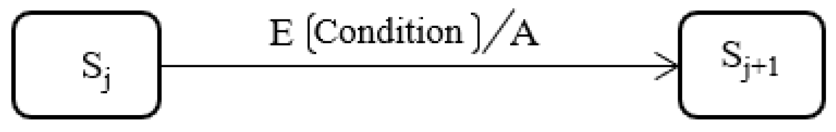
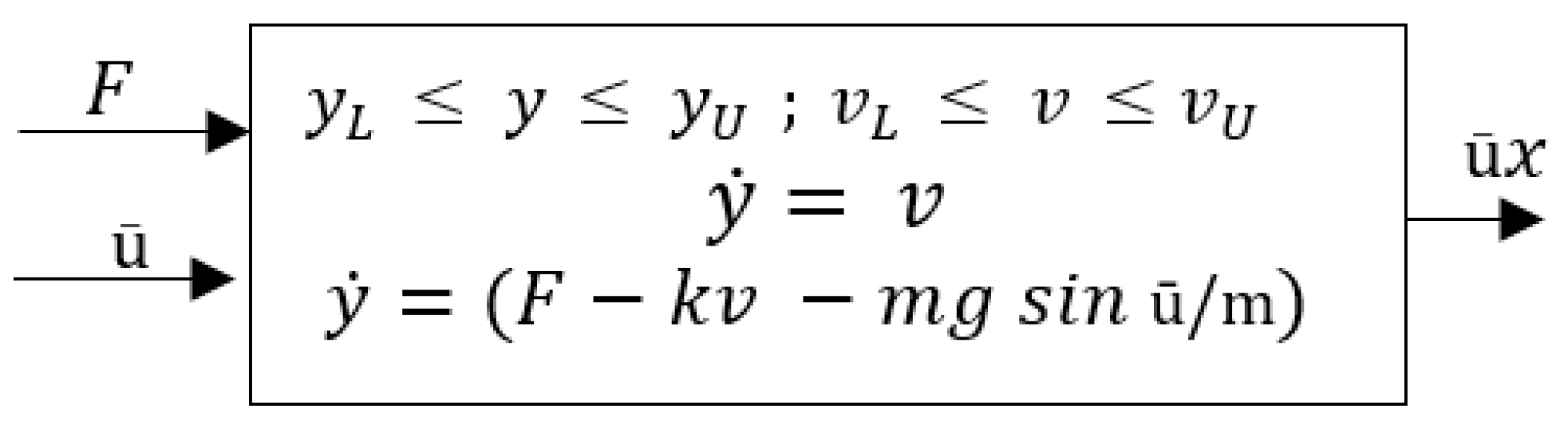
3.1. State Transition Diagram

The basic idea of STD is to define a machine that has a number of states. STD describes all of the states that an object can have, the triggering event under which an object changes its state, the guard conditions that much be fulfilled before the state changes, and the actions for state transition [18]. The STD can be defined as STD <S, T, E, A> where S is a set of states, and S = ( S 0 ,     S 1 ,     S 2 ,   ,   S f   ) starts from the initial state S 0 and reaches the end state S f . T represents a set of transitions T = (   T 1 ,     T 2 ,   ,   T n ). E is a set of events, and A = ( a 1 ,   a 2 ,   ,   a n ) is an action or series of actions to be taken for a state transition. The state transition diagram represented by the above components is shown in Figure 1.

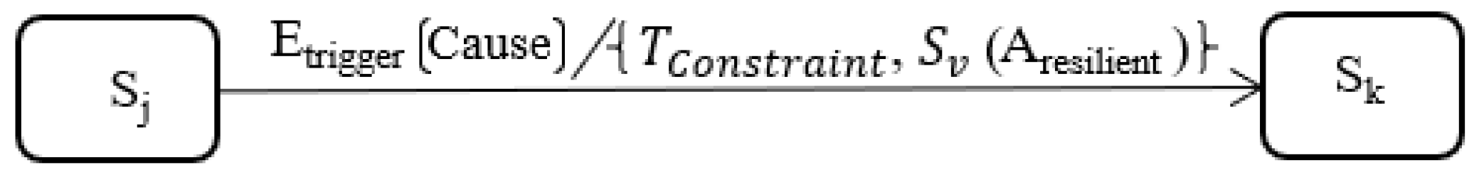
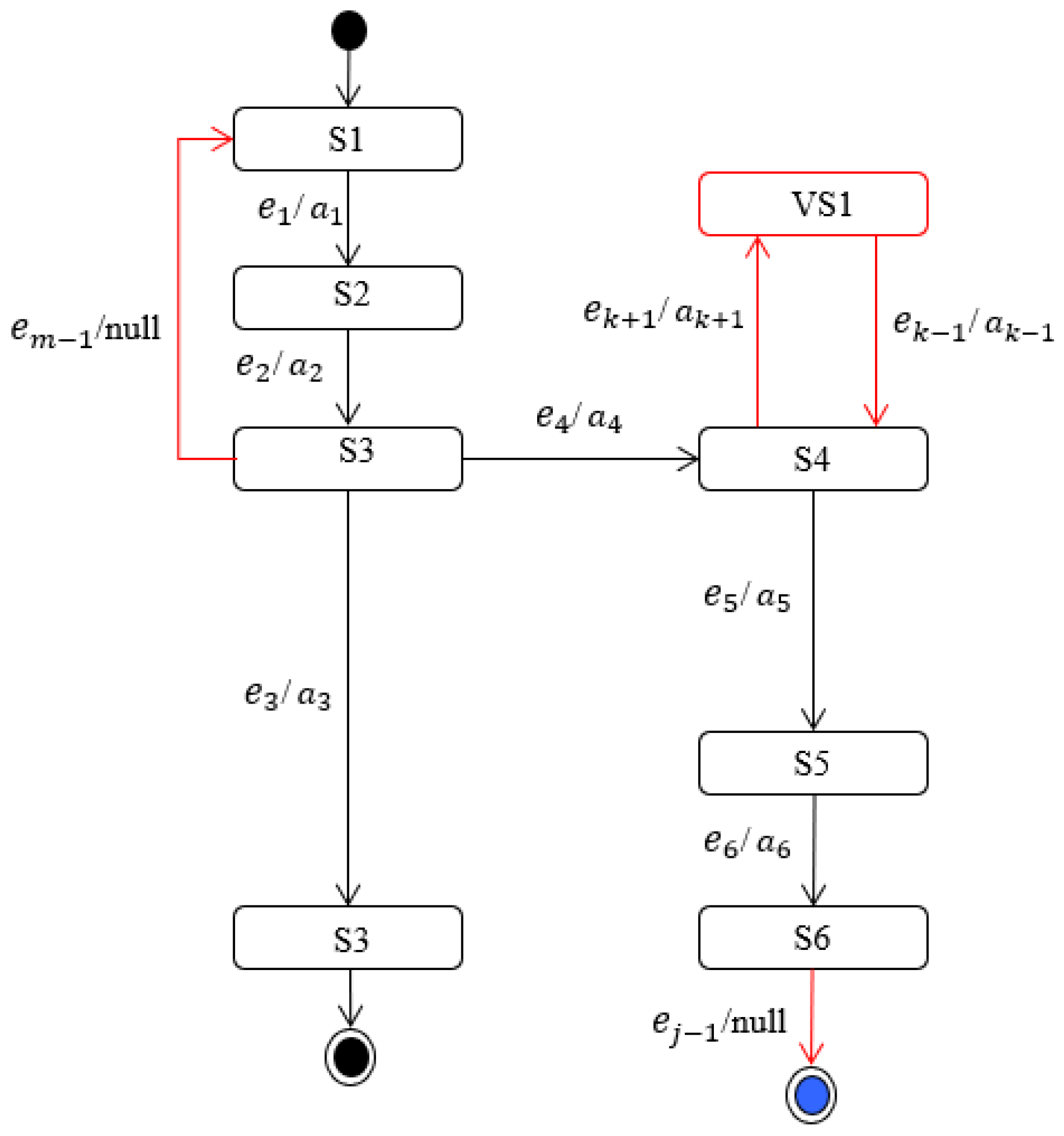
3.2. Resilient State Transition Diagram

A system is said to be resilient if it has the required capability to face any adversity. A system’s resilience can be achieved by avoiding, withstanding, recovering from, evolving, and adapting to any adversity [19]. Hence, we can say that resilience is the ability of a system to withstand a major disruption/failure within acceptable degradation parameters and recover within an acceptable time [20]. Therefore, resilient CPSs need to be designed with a major focus on collaboration and a dynamic context. We extend the traditional state transition diagram for context change, which is a superset of STD. The R-STD is defined as below.
[Definition] R-STD = <S, T, E, A, Etrigger, Tconstraint, Aresilient>
where S is the set of system states, including the next expected state or defined state S_e, and S_v is the virtual state, which is not defined in the system; however, it is determined at the run time. Therefore, S is defined as S = <Sj, S_e, S_v, Sf>, it starts from an initial state Sj, and goes through a number of transitions, including the next expected stated or virtual state and reaches a final state Sf. T represents a set of transitions and is defined as T = <T_e, T_v>. Similarly, T_e represents the set of already identified state transitions, and T_v denotes a set of newly added transitions. The transition t in T_v produces an output S_v. Etrigger is a triggering event that causes uncertainty in the system. Tconstraint is the temporal constraint that needs to be fulfilled in order to proceed with the resilient state transition. Aresilient represents a number of actions performed in order to achieve resilience in the system. The Aresilient is defined as Aresilient = < a 1 ,   a 2 ,   ,   a n >. The R-STD represented by the above components is shown in Figure 2. Also, Our R-STD is an extension of the conventional STD. Therefore, R-STD ⊇ STD is established.

4. Proposed Approach

When multiple CPSs collaborate to accomplish a task, the safety and sustainability of the system may not be ensured due to complexity, variability, and heterogeneity. All these factors may lead to uncertainty in the system because such factors were not sufficiently considered in developing a single CPS. Uncertainty is divided into two categories: aleatory uncertainty and epistemic uncertainty [21]. The aleatory uncertainty can arise due to natural variability, i.e., the unpredictable physical environment in the case of autonomous cars. The epistemic uncertainty is the form of uncertainty that stems from the degrading performance or by the aging of a sensor or an actuator. These two significant uncertainties are the most important challenges in developing collaborative CPSs that collaborate in real-time to achieve a common goal. Due to its criticality and collaborative behavior, the failure in collaborative safety-critical systems cannot afford the fail-safe notion. In case of failure in CCPS, such as platooning systems, the system should show a graceful degradation and return to the original state in case of temporal failures. Otherwise, the least resilient transition should be activated, describing a safe exit of a vehicle from the platoon.
We propose an approach (as shown in Figure 3) where we first analyze the collaborative behavior of the platooning system and extract variability factors that cause the system’s failure. For instance, limitations in the perception system can cause the unintended braking of a platooning vehicle due to weather conditions (fog, rain, snow, etc.). Therefore, variabilities are integrated with the state transition diagram and obtain a resilient state transition diagram that considers variabilities and other failure factors, such as Vehicle to Vehicle (V2V) communication failure, Vehicle to Leader (V2L) communication failure, and ego-motion measurement failures. In the following subsection, we describe our approach in detail.
The platooning vehicle’s state is defined by two variables: the position y and the angle v, which defines the orientation of the vehicle with the angular speed. The output can be the angle with some angular speed as shown in Figure 4—the n and h show input and output functions, respectively.
If we take the position of the vehicle at the horizontal axis y 1 , vertical axis y 2 , and the orientation angle of the vehicle y 3 , at time t, then:
y 1 ˙ = v 1   s i n   y 3 y 2 ˙ = v 1   c o s   y 3 y 3 ˙ = v 2   v = [ v 1   v 2   ] , y = [ y 1 y 2 y 3 ]  
where v 1   is the forward velocity and might have the constraint to the range v L     v 1     v U   and v 2 defines the rate of angular change such that v L     v 2     v U   . The y 3 ˙ = v 2   tells that the rate of change of state variable y at each time t equals the variable v at time t. The model in Figure 4 shows a continuous-time model for platooning vehicles without variability. We observe that at time t, the system produces a particular angle with an angular speed by giving force or thrust and some particular angle as an input to the system. The above system model assumes that platooning vehicles move on a flat road without contextual change, i.e., fog, rain, road grade, etc. The system model with variability will be discussed in Section 4.1.

4.1. Collaborative Behavior of CPSs and Variability

In CPSs, the physical environment, which is to be controlled or monitored, is modeled by a component called “Physical World” which is monitored by sensors, and the information obtained through sensors is processed, and a decision is made in “Cyber World”. The decision can be reflected back to the physical world through actuators. However, uncontrolled factors can influence the cyber-world, which is called variability in our study. For example, in autonomous platooning systems, the physical world is the road and roadside infrastructure which is controlled by a number of sensors. “Cyber World” task is to analyze the road and process the information to achieve safe platooning driving. The fog, rain, snow, etc., on the road, are the variability factors that can reduce the performance of perception system and cause failure in the system.
In an autonomous platooning system, vehicles drive in a group by following a leader with a short inter-vehicle distance to achieve common goals, i.e., reducing traffic congestion and increasing fuel efficiency [22]. Each vehicle in the platooning system is considered as a single CPS. Along with other challenges, the platooning system faces variabilities (e.g., fog) that trigger uncertainties and cause failure in the system. This type of uncertainty originates from a failure-free system’s unintended behavior due to its performance limitations, lack of robustness with respect to the context that might disturb sensors or insufficient situational awareness. The difference in context, infrastructure, time, and place in collaborative CPS is defined as the variability in this paper. For instance, in the case of medical CPSs, the infusion pumps inject a given drug (insulin) into the human body; the effect of the insulin on the physiological parameters (e.g., blood glucose concentration) varies over space as well as time. The effect is maximum at the sight of insulin and decreases at the locations away from the sight being affected by blood perfusion. This example shows variability in time and place in CPSs.
The dynamic CPS model is shown in Figure 5. Assume that the platooning vehicles are moving in a single dimension on a highway. Let us assume that we want to consider the grade of the road (spatial variability): On a downhill road condition, the weight of platooning vehicles adds to the force applied by the engine. On an uphill road condition, the vehicle weight works against the force applied by the engine. The cruise controller needs to adjust the force F to maintain net velocity in the autonomous platooning system. The system model with spatial variability (road grade ū) can be modeled with additional input, denoted as ū. The positive ū may indicate an uphill slope, and the negative ū may indicate a downhill slope. The vehicle’s weight equals to mg in the vertically downward direction where g = 9.8 m/s2 is the gravitational acceleration. The system model with variability is shown in Figure 5.

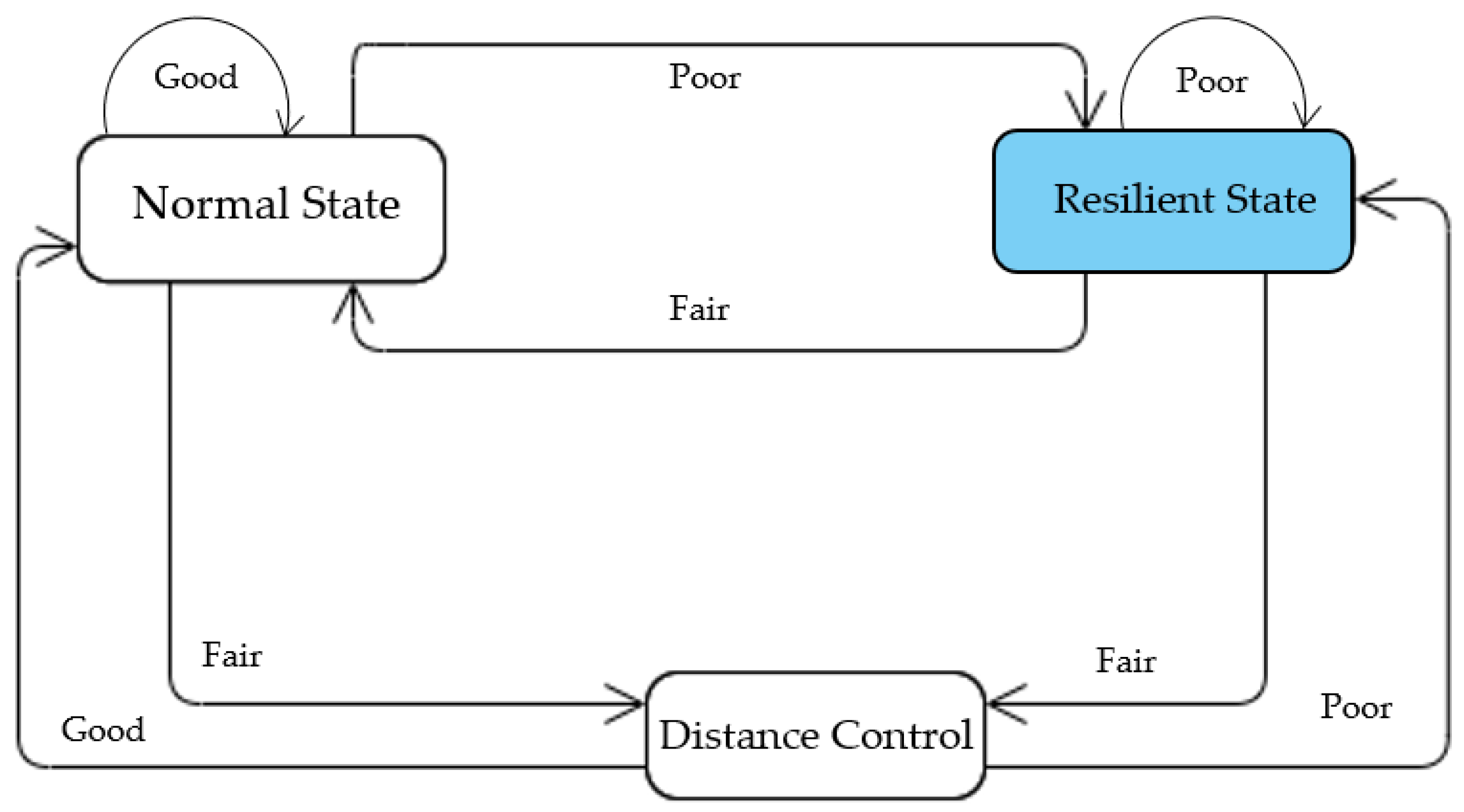
4.2. Resilient State Transition for Variability

As mentioned in Section 2, the R-STD covers how to handle system behavior regarding environmental variabilities. For example, an autonomous platooning vehicle drives safely when it faces variabilities such as dense fog, rain, snow, etc. The system transitions during a variable situation are fundamentally not defined in the system, i.e., it was not considered at design time. They can occur dynamically during operation time. The states and transitions for variabilities are shown in Figure 6. For instance, the state VS1 is dynamically generated for a specific environmental variability. The red arrows show the resilient transitions, and the red rectangle with rounded corners shows a system’s dynamically created virtual state for a specific variability. Three transitions are possible in R-STD in case of variability. First, the system can dynamically generate a new state that is unknown at design time (S4 to VS1). Second, the system can also go to the initial state to cope with variability (S3 to S1). Third, the system can go to the ending state in case of variability (S6 to termination state). Finally, the decision can be assessed based on the severity of the influence of variability on the system.
The procedure of state transition is mentioned in Algorithm 1. Let S be the set of states for events in the system. The event can be expected for which a set of actions A {a1, a2, …, an} are described, and the system transits to the defined states. The event can be an unexpected event if there is no defined set of actions for those events. In case of an unexpected event, a set of resilient actions Ra {Ra1, Ra2, …, Ran} are taken, and the system goes through a number of resilient states Rs {rs1, rs2, …, rsn} to prevent the system failure.
Algorithm 1 Resilient state transition
1.Start
2.S {s0, sb, sh, …, sm} where S0 is the initial state and sm is the final state
3.E {e1, e2, …, en}
4.A {a1, a2, …, an}
5.Ra {ra1, ra2, …, ran} where Ra is the resilient actions.
6.RS (rs1, rs2,, …, rsn) where Rs is the set of resilient states
7.Initialize s = 0, a = 1, e = 1
8.If (en ∈ E & an ∈ A)
9.For ∀ en ∈ E & an ∈ A
10.                 If ∃ sn
11.                  Go to next state sn → sn ∈ S.
12.                 EndIf
13.           EndFor
14.EndIf
15.Else
16.       For ∀ en ∉ E
17.          en is Etrigger
18.          If (Etrigger)
19.           ∃ ran ∀ en → rsn
20.           Go to resilient state sn → sm ∈ RS
21.           CreateVirtualState(VSm)||terminateProcess||goto initial state
22.         EndIf
23.       EndFor

5. Proposed Approach

A platoon driving system maintains a short inter-vehicle distance among members and communicates with each other to drive continuously and safely. The short distance can be achieved by acquiring real-time information about the driving behavior of preceding vehicles in the platoon. This real-time information is obtained by combining onboard sensors and wireless communication with platoon members.
Therefore, if some communication failure or sensor failure occurs, the required information may not be available, and driving within a short distance may pose a serious safety threat to the platooning system. Compared to the fail-safe mechanism of systems, where, e.g., a shutdown of an actuator leads to a safe system state, autonomous vehicles should be fail-operational, i.e., failure of a vehicle during operation on the road is unacceptable. Hence, failure should be compensated, and compliance with safety constraints must be ensured even under failure incidence. In the platooning system, this means that the distance between vehicles always has to be large enough to allow for an autonomous reaction to the vehicle’s sudden braking in front without risk of collision. Furthermore, individual platoon members should be able to adjust reaction time that depends on the quality and speed of information about the behavior of preceding vehicles.
The head of the platoon is called the leader, and other following member vehicles are called followers. The platooning system is based on C-ACC, where vehicles can communicate to create synergy in their cooperation. A platoon system’s member vehicle can also be in an ACC mode, where the vehicle depends on the onboard sensors only instead of depending on other vehicles’ information. This mode helps fail-operational cases when a vehicle loses its communication with other vehicles. A platoon driving example is shown in Figure 7, where a leader can communicate with the followers, and the followers can also communicate with each other using Vehicular Adhoc Network (VANET).

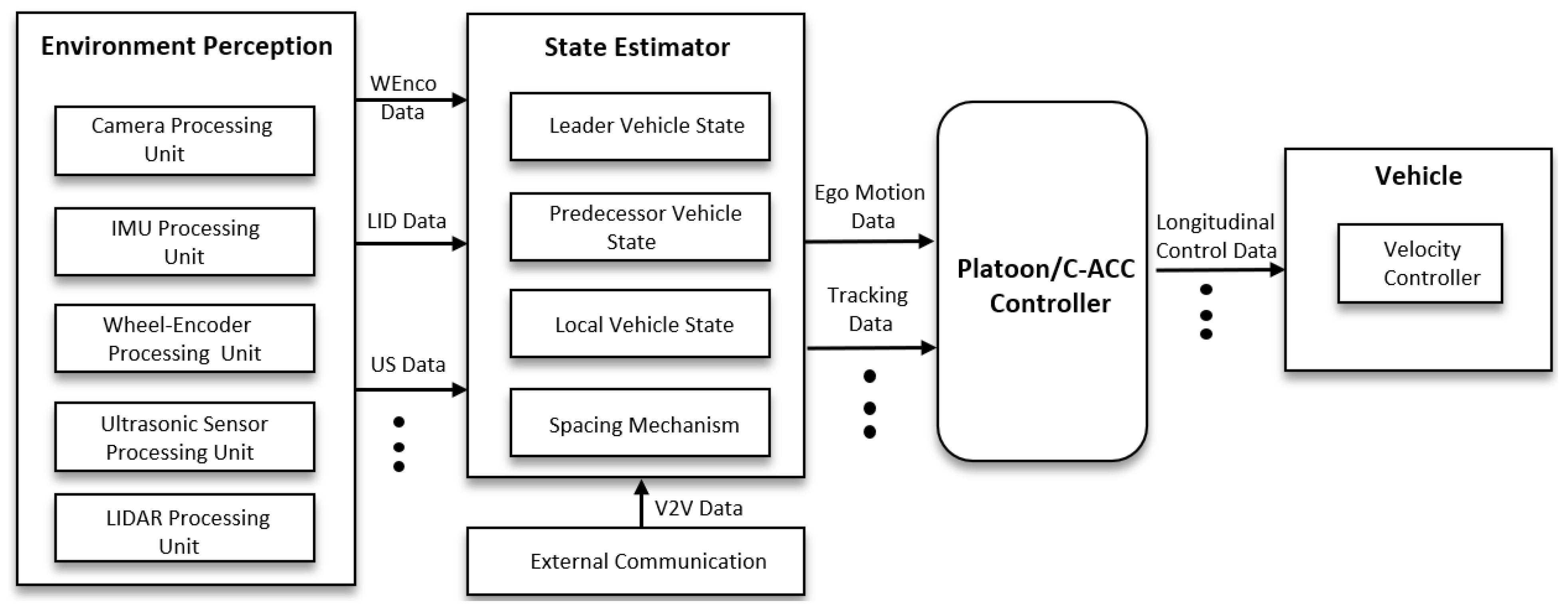
5.1. System Architecture

Figure 8 shows a platooning system architecture. Each vehicle in the platooning system is equipped with LIght Detection And Ranging (LIDAR) and ultrasonic sensors to measure the distance to the front vehicle. A fusion of LIDAR data and Ultrasonic Sensor (US) data is carried out to detect measurement faults. Additionally, an odometry unit is placed on each vehicle to determine their behavior, i.e., velocity, acceleration, position, and distance covered. Each vehicle also has an onboard Inertial Measurement Unit (IMU) and a camera sensor. The flow of the signal goes from left to right as shown in Figure 8. The input relates to each layer, and the output relates to actuator control. For example, in each layer in the environment perception layer, the relevant processing unit processes each sensor data.
The environment perception layer includes an IMU component, which is only used when the wheel encoder fails. The Wheel-Encoder (WEnco) processing unit obtains and processes odometer data. The state estimator layer estimates the motion states of the predecessor, leader, and itself, which is achieved by fusing the data from both V2V communication and local sensors. The platooning system also uses a spacing policy to determine the inter-vehicle distance according to vehicle dynamics, weather, road condition, and communication quality.
We consider Kesting et al. [23] Intelligent Driving Model (IDM) for the implementation of ACC and C-ACC. The IDM for the platooning system is modeled as in Equation (2).
A β = A m a x [ 1 ( v β v 0 ) δ ( s   ( v β , Δ v β ) s ) 2 ] s ( v β , Δ v β = s 0 + v β   T d i s t a n c e   + v β , Δ v β A m a x B m a x 2
where β is the platooning vehicle being considered, β 1 is the vehicle in front, and s 0 , Δ v β , T d i s t a n c e   shows safe distance, the difference in velocity, and time gap with the platooning vehicle in front. A m a x , B m a x represents the maximum acceleration and braking values, respectively. δ represent the free acceleration exponent that characterizes how the acceleration decreases with velocity.
The C-ACC is used to drive the vehicles autonomously in a platoon. Various longitudinal control algorithms are used to determine the target velocity [24] in C-ACC mode. The velocity controller is responsible for regulating vehicle and motor speed based on the provided target velocity.

5.2. Normal and Hazardous Scenarios

In the platooning system, a platooning member vehicle can determine the distance to the front vehicle. The platoon member vehicle can also measure its motion data such as speed, acceleration, position, and distance covered. The platoon member vehicle can receive the motion data from its immediate front vehicle and the platoon leader. In the case of normal platooning operation, the inter-vehicle distance is measured by LIDAR and US data fusion. The wheel encoders are used to calculate a vehicle’s ego-motion.
In order to obtain the property of resilience in a safety-critical system like a platooning system, failures should be compensated, and driving behavior for platooning vehicles should rely on resilient state transition or graceful degradation. The resilient state transition defines steps where a system can select the best available modes in the presence of a failure. We consider three kinds of failure scenarios: (a) object detection failure or obstacle detection failure due to environmental (for leader vehicle) variability, e.g., fog, rain, etc., (b) ego-motion estimating failure, and (c) communication failure. The default method used for environment perception is the fusion of LIDAR and US data. Likewise, the wheel-encoder is used to obtain the vehicle’s ego-motion, and V2V, or V2L, is used to communicate with vehicles or leaders, respectively. However, in case of a failure, there should be alternate ways to achieve resiliency. For example, if the LIDAR sensor fails to work, US data can be fused with a stereo camera to solve the perception failure. If the US fails, the camera can be used alone without any fusion to achieve the fail-operation property of safety-critical systems.

5.3. Resilient State Transitions

R-STD is made by combining the concept of resilience and the state transition diagram concept. The basic idea of the state transition diagram is to define a machine with inherent resilience property. The concept of resilience is the ability of a system to withstand a major disruption due to adversity (variabilities and other factors) within acceptable degradation parameters and recover within an acceptable reaction time while ensuring system safety. Thus, the R-STD emphasizes safe transitions from one state to another to achieve the fail-operation goal. This section explains the R-STD for perception sensors failures, ego-motion estimation failures, and communication failures.

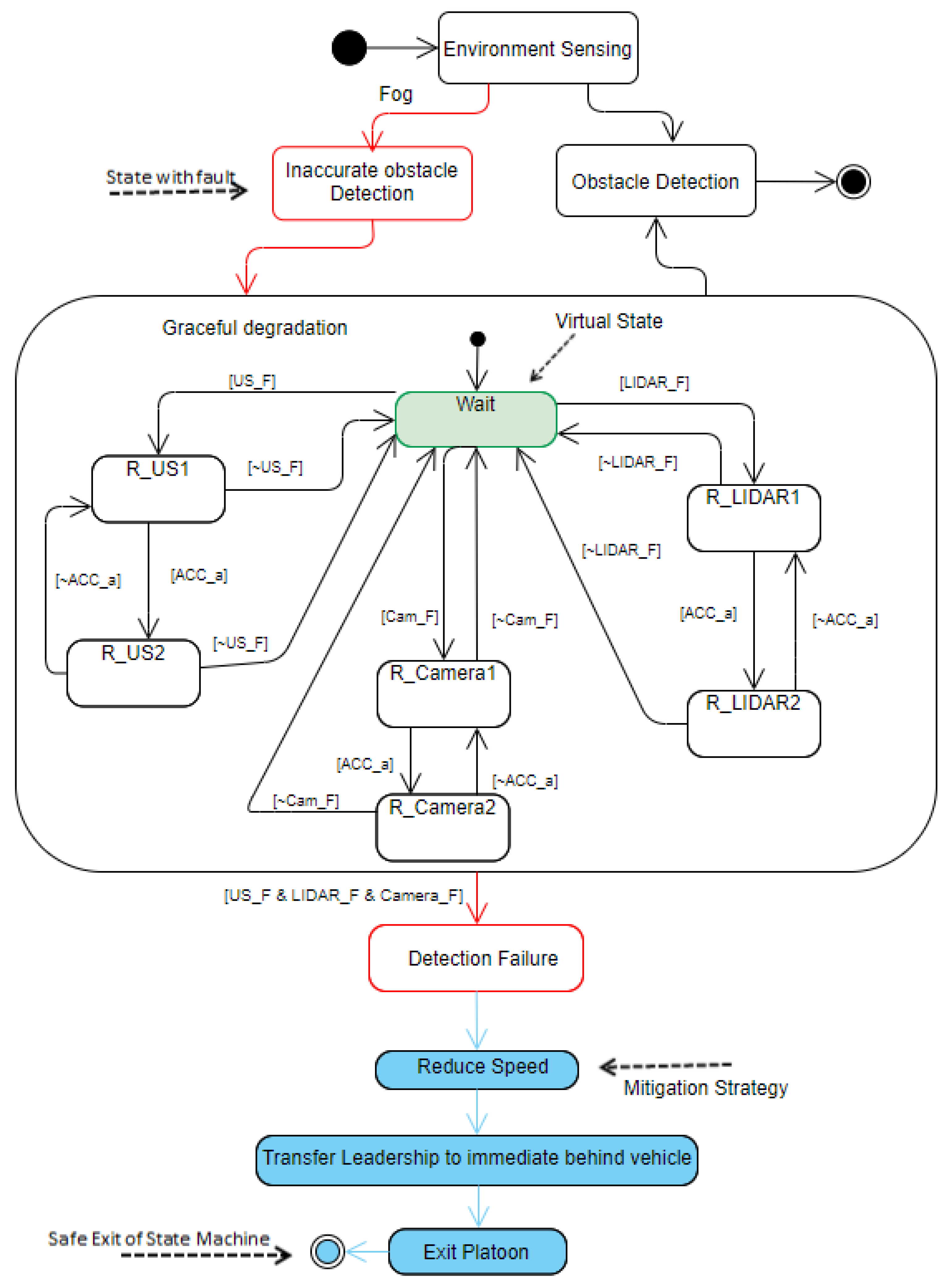
5.3.1. Environment Perception Failure Due to Fog

The fusion of LIDAR data and US sensor data provides a vision to the platooning leader. In case of US failure (US_F) or LIDAR sensor failure (LIDAR_F), it would be no longer possible for the platoon leader to use the sensor fusion to achieve the precise perception; however, the vehicle can still rely on other sensors, such as the camera. The camera does not provide a clear vision; therefore, as an alternative, it increases reaction time for the vehicle to adjust itself and avoid potential collision events. Figure 9 shows the R-STD for perception failure in the platooning system due to fog. The red boxes show failure states or faulty states, and blue boxes show mitigation strategies. As mentioned, the fusion of LIDAR data and US sensor data provides a vision to the vehicle. When the US sensor fails, the fusion of Camera data and LIDAR sensor data can be used to provide a vision to the platooning leader. As shown in Figure 9, when the US faces some failure (US_F), it switches to resilient degradation (R_US1) and continues to provide vision by fusing its data with LIDAR. If the performance continuously decreases, the US goes to the next level of degradation (R_US2) when ACC mode is activated. When the US recovers from failure (~US_F), the system returns to its original state. This happens with failures of temporal type. A similar case can be followed with the camera and LIDAR sensors when they face failures during operation. When the sensors fail (US_F and LIDAR_F), the system switches to the least resilient state and tries to recover from it in a given response time. If one of the sensors (~US_F|~LIDAR_F|~Cam_F) recover from failure, the system returns to its original state. Otherwise, the leader vehicle assigns its leadership role to the immediate rear vehicle and safely exits from the platoon.

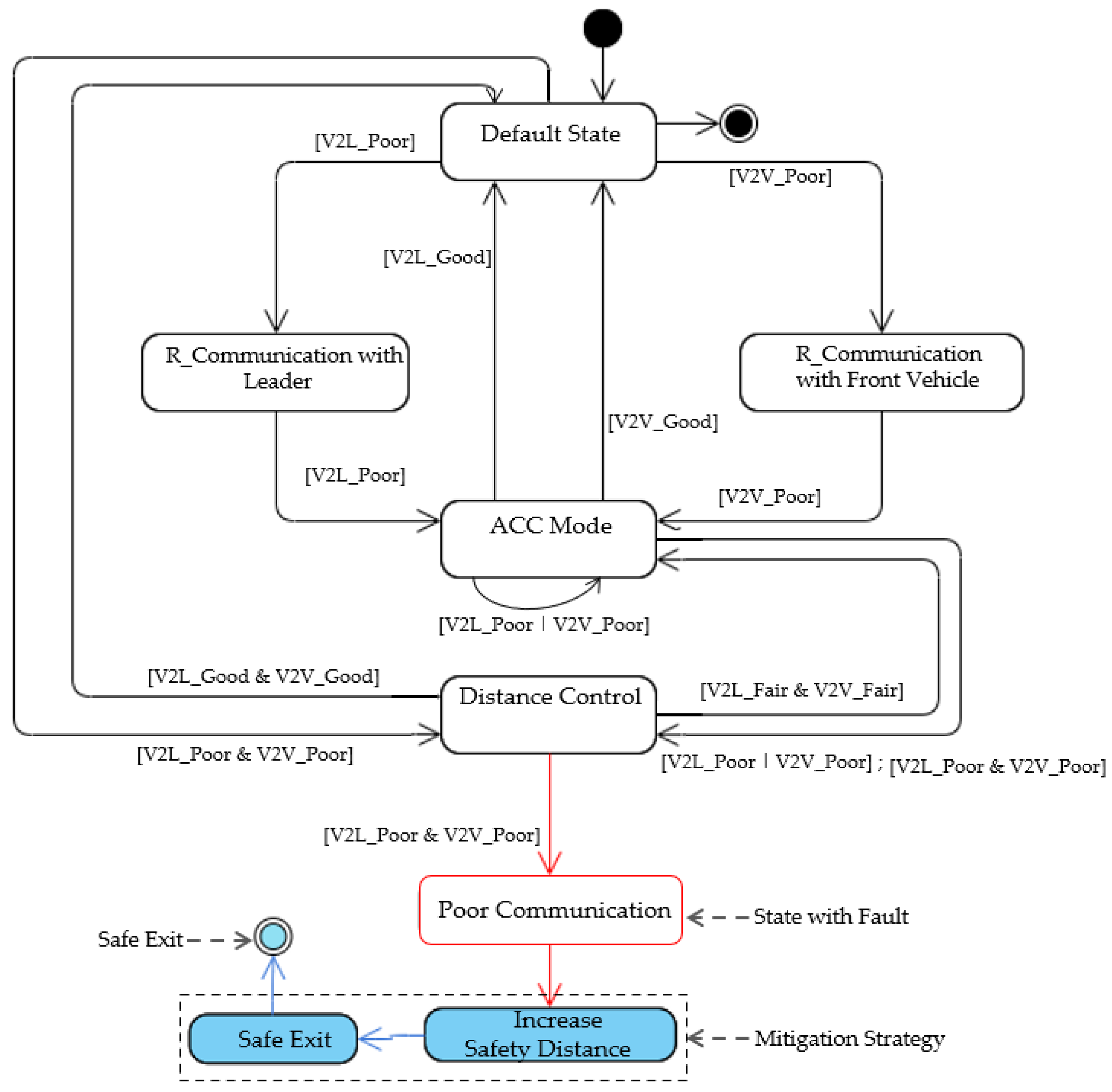
5.3.2. Communication Failure

For communication failures, we propose a new resilient transition model capable of degrading the platooning system performance when a communication failure occurs, as shown in Figure 10. We draw R-STD for V2V and V2L (Figure 11) communication failures based on the resilient transition model for communication failure.
In a platoon driving system, each member communicates with the front vehicle and the platoon leader to collect information, i.e., target safety spacing, target speed, current speed, and location of the preceding vehicle. To achieve the target spacing for the platoon, the C-ACC in each platooning vehicle will accelerate or decelerate according to the difference between actual distance and target spacing slot to the preceding vehicle. Hence, if the difference is negative, the vehicle must decelerate so that the distance to the preceding vehicle meets target spacing. Otherwise, the vehicle must speed up.
We categorized the communication conditions between V2V and V2L into good, fair, and poor categories. These conditions can be determined by the transmission or loss of data packets according to different scenarios during operation (the communication in detail is out of the range of our research focus) [25].
As shown in Figure 11, the C-ACC controller is considered a default state in our transition model because it can maintain a shorter inter-vehicle distance among the platoons. The ACC is considered to be a resilient state because of its high time-headway requirement. The distance control signifies inter-vehicle distance adjustment without switching to a resilient state or default state. The system only transits to a resilient state if the V2V communication is determined to be poor. If the connection quality becomes fair, then the inter-vehicle distance is increased to avoid a potential collision. The control manager continuously monitors the status of V2V (V2V in front) and V2L communication. Suppose communication is determined to be poor ([V2V_Poor] or [V2L_Poor]). In that case, the system transits to a resilient state (i.e., ACC) to increase the inter-vehicle gap. Otherwise, it goes back ([V2V_Good] & [V2L_Good]) to the default state (i.e., C-ACC) and minimizes the inter-vehicle distance. When the communication between V2V is poor and V2L is Good, the system must switch to resilient mode (ACC mode) to activate onboard sensors. The ACC accelerates or decelerates based on the linear combination’s relative speed of vehicles and deviation of current distance from the desired inter-vehicle gap:
A A C C = y v ( v 1 v 2 ) + y r ( r r d e s t a n c e )  
where v 1 is the speed of the vehicle in front and v 2 is the speed of the following vehicle, r represents the inter-vehicle distance and   r d e s t a n c e is the desired inter-vehicle distance in the platooning system. y v and y r are the control parameters that have to be adjusted accordingly.
The C-ACC extends Equation (3) by adding the acceleration of the preceding vehicle as shown in Equation (4).
A C A C C = a 1 + y v ( v 1 v 2 ) + y r ( r r d e s t a n c e )
Therefore, if the communication fails, then a 1 will not be known to following vehicles, and ACC will be activated automatically as the vehicle’s speed in front and following vehicles and inter-vehicle distance can be measured using onboard sensors.
Similarly, if the system recovers its failure, and V2V and V2L communications become well ([V2V_Good] and [V2L_Good]), the vehicles return to default mode (C-ACC) and decrease the inter-vehicle distance to default. On the other hand, suppose the V2V and V2L communications become poor ([V2V_Poor] and [V2L_Poor]). In that case, the target vehicle again switches to a least resilient state (Poor Communication state in Figure 11), increases the distance between ego vehicle and the front vehicle, and leaves the platoon with graceful degradations (Safe Exit state in Figure 11). Figure 11 shows these communication failures with resilient state transitions.

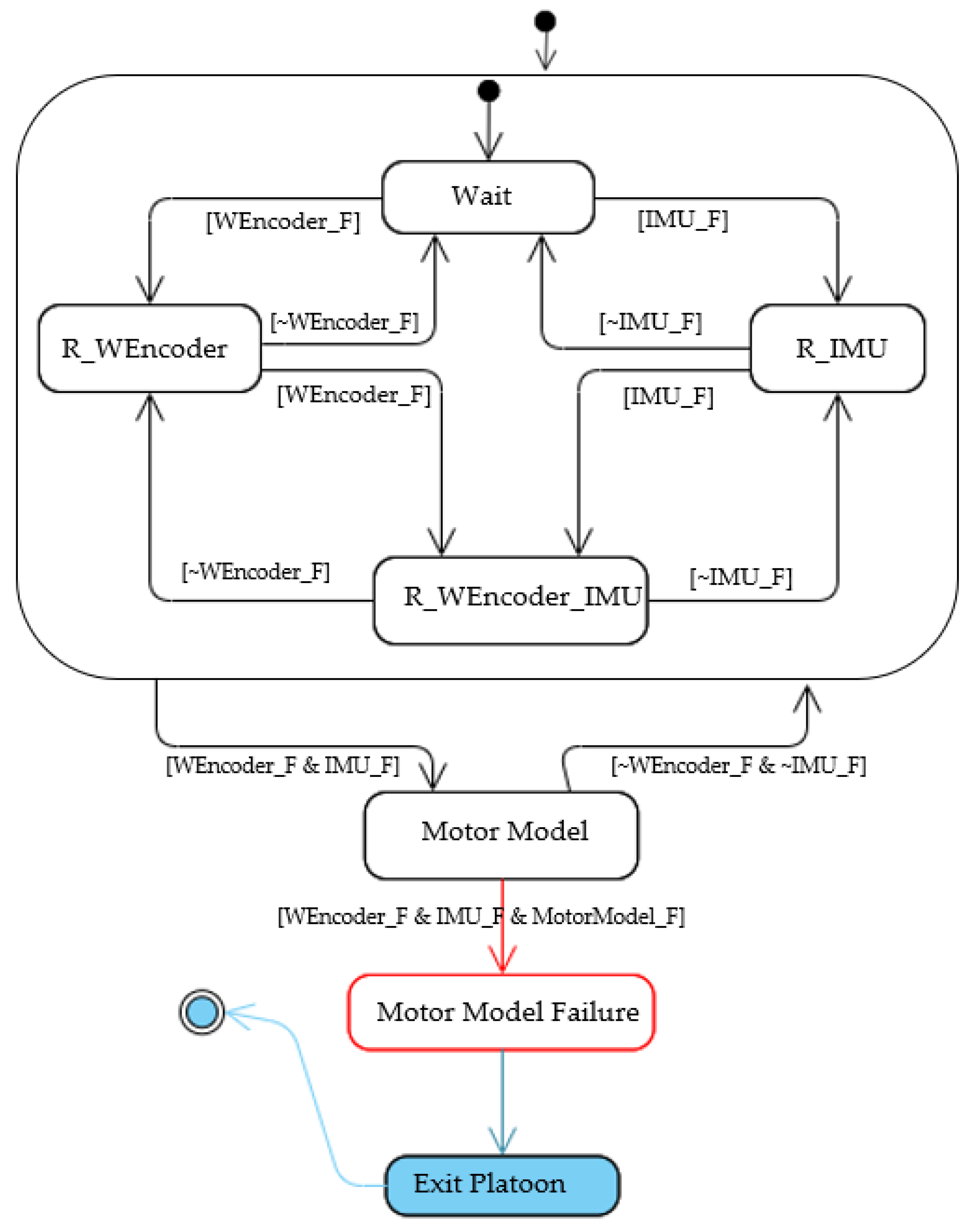
5.3.3. Estimating Ego-Motion Failure

Accurate estimation of the ego-motion of a platooning system is critical for self-diagnostic and decision making. The ego-motion in autonomous vehicles can be determined using a number of sensors [26,27]. Among them, cameras, IMUs and wheel encoders are famous because of their ubiquity and low cost while providing sufficient information for ego-motion estimation.
If a fault occurs in the wheel encoder sensor (WEncoder_F), the acquisition of acceleration, speed, and covered distance, collectively known as ego-motion data, will be affected.
In case of a fault in a wheel encoder sensor, there should be a mechanism in which platooning vehicles can still acquire ego-motion data. As an alternate sensor, an IMU can be used to acquire 3-axis acceleration data when necessary. However, this information may not be precise, but it can be an acceptable resilient alternative to the wheel encoder. In case of a fault in IMU (IMU_F), we know that there is still an opportunity to reach the vehicle’s own velocity using the motor model as mentioned in [7]. In Figure 12, we show the resilient state transitions in case of a wheel encoder failure. The red box shows a failure state. From the initial state, the system switches itself to a resilient state (R_WEncoder). It depends on IMU to determine its own acceleration when a fault occurs in the wheel encoder sensor. Suppose the IMU faces some fault (IMU_F). In that case, the system switches to an acceptable resilient transition, i.e., the motor model, which estimates engine speed based on the voltage and current without a physical sensor. Even though its information is not accurate enough, it can be an acceptable resilient state to avoid any damage to the system and achieve the fail-operational goal. If the system recovers IMU failure within a given reaction time ([~IMU_F]), the system returns to its original state.
Similarly, when the wheel encoder encounters some failure ([WEncoder_F]), the system goes to a resilient state and relies on the IMU sensor to determine its own acceleration. If both IMU and wheel encoder becomes faulty ([WEncoder_F & IMU_F]), the system goes to a resilient state ([R_ WEnconder _IMU]), and a motor model is used as an alternative to getting own acceleration information. If the motor model encounters a failure, the vehicle immediately exits the platoon safely.

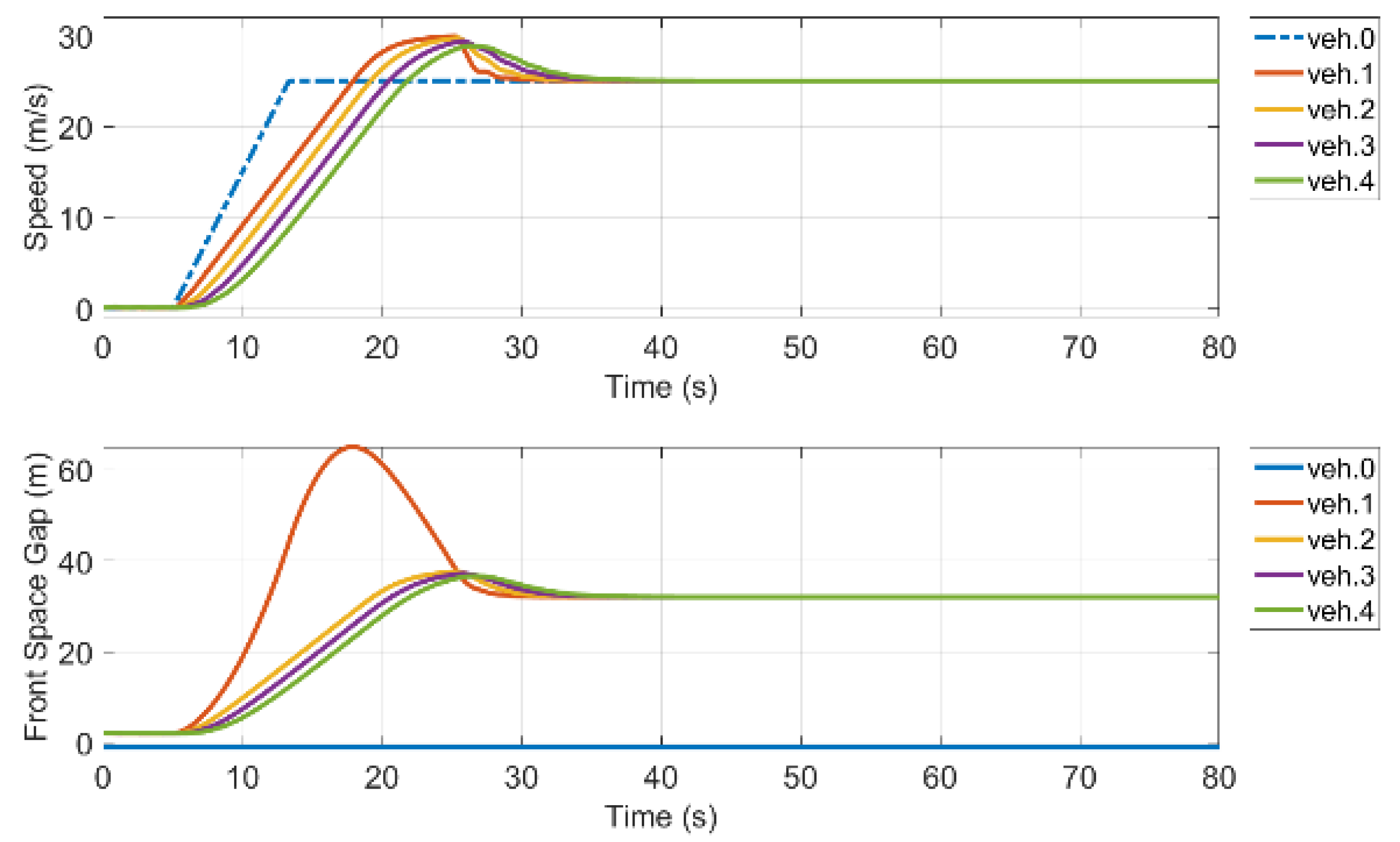
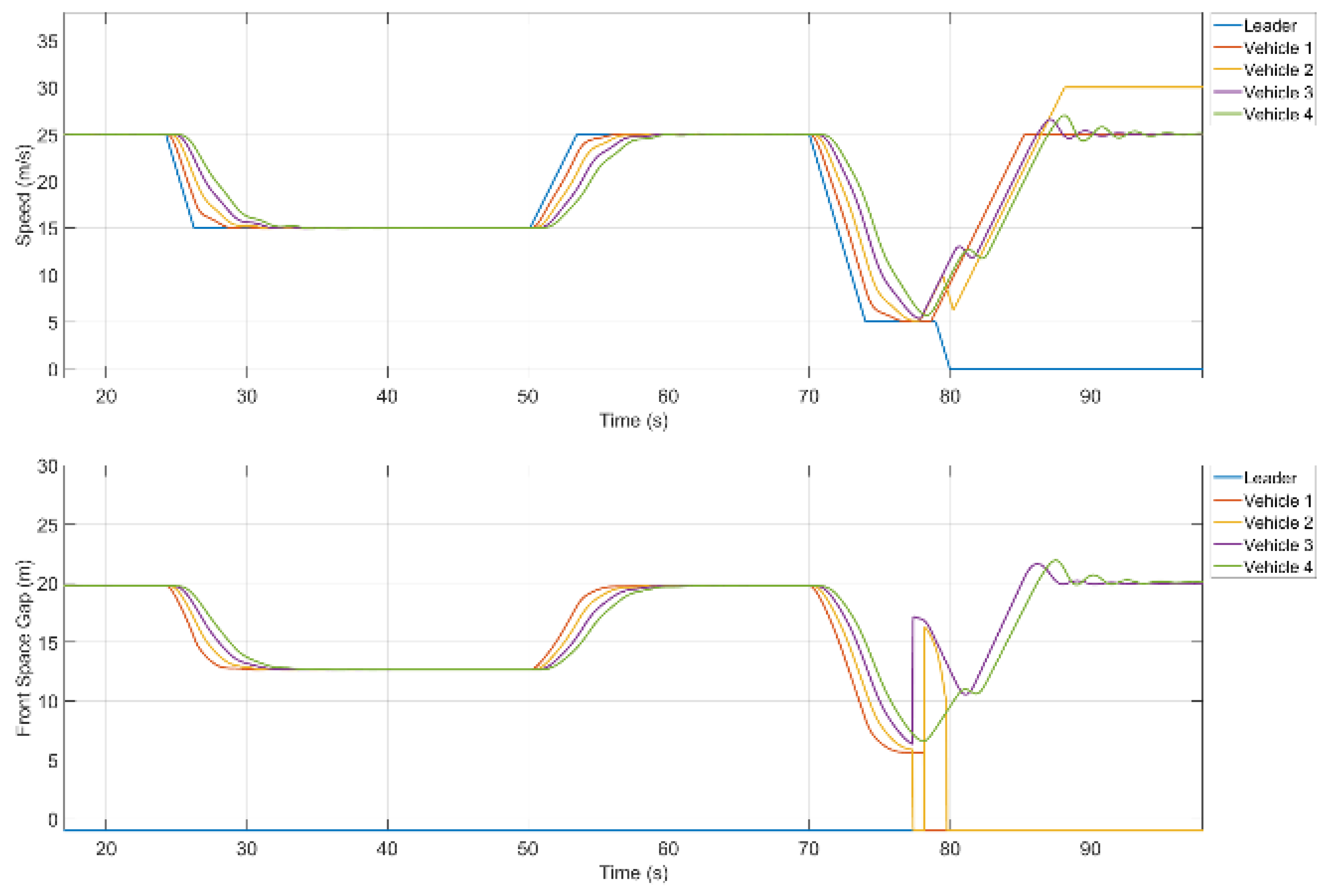
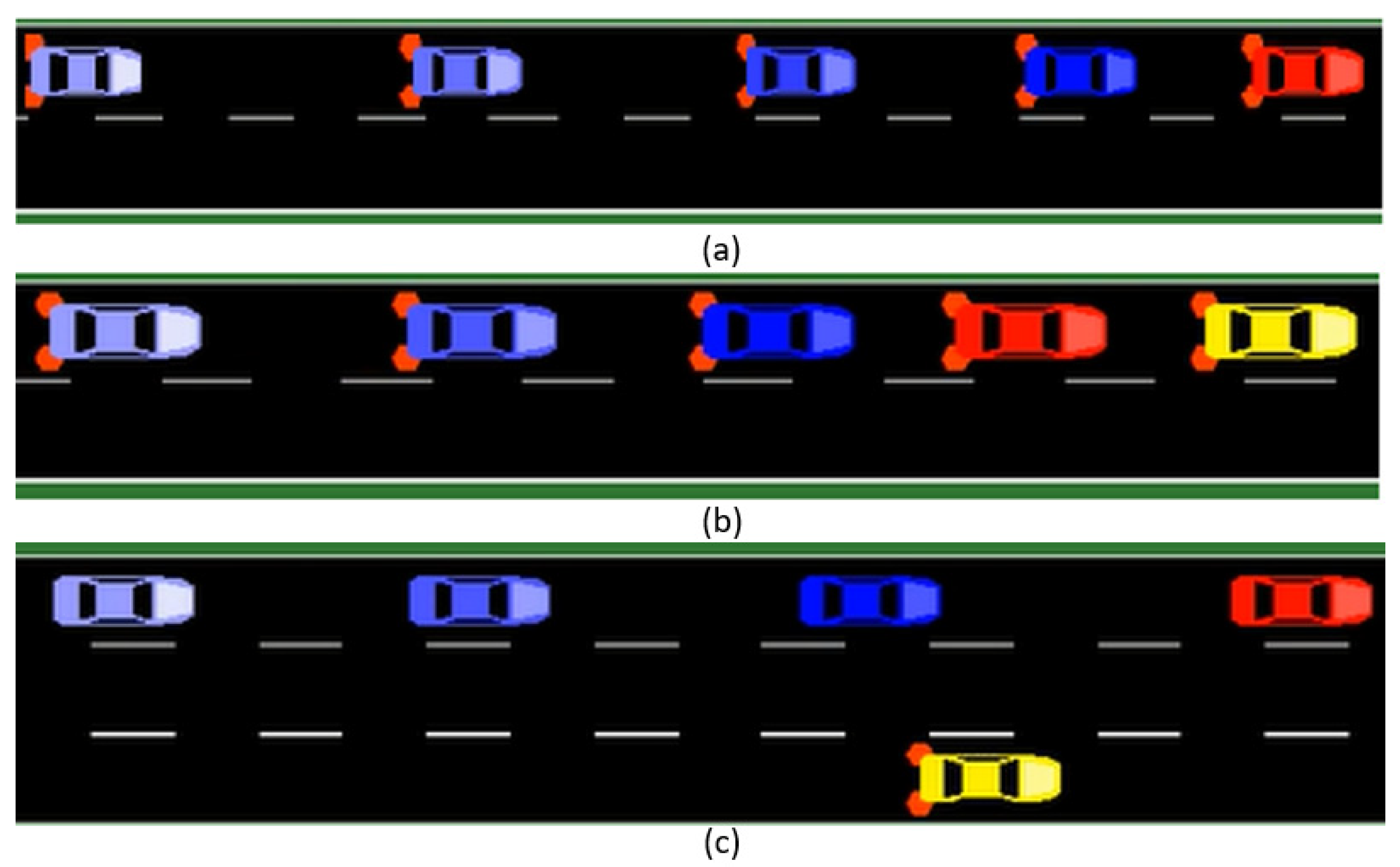
6. Verification with VENTOS

The VENTOS (Vehicular NeTwork Open Simulator) is a new open-source integrated simulation framework [8]. It is made up of various modules, including OMNET++, and Simulation of Urban Mobility (SUMO). OMNET++ [28] is an open-source component-based simulator that captures the wireless communication simulation in VENTOS where IEEE 802.11p protocol for V2V communication in Veins (Vehicles in Network Simulation) framework is used for wireless communication C-ACC vehicles. SUMO [29] is also an open-source, microscopic, continuous-space, discrete-time road traffic simulator, which is developed by the Institute of Transportation Systems at the German Aerospace Center and adopted in VENTOS as a traffic simulator.
We select VENTOS and its platooning system because (1) it is an open-source simulator that includes SUMO as a traffic simulator. For instance, it is quite easy to generate traffic maps for simulations using SUMO than other available simulators, (2) VENTOS is a mature simulator, and several studies have already used it [12,30].
In the simulation, we first generate the scenario by random configuration, and then the simulation is performed on generated hazardous scenarios to see the effectiveness of our proposed approach.
Normal Scenario: In this simulation, we implemented a platoon of size five (one leader and four followers as shown in Figure 7), where first we checked the speed and distance of the platooning system without any failure and recorded its speed and distance in Figure 13. This is carried out to ensure that the platooning system is working fine without any failure. As can be seen, the speed of the following vehicles fluctuated initially and adjusted its speed with time. This is because, before platooning, the vehicles were located at a different distance. We also see that the leader vehicle (V0) was a little far from its immediate rear vehicle, V1. Therefore, initially, there was a considerable distance between the leader and the V1. However, the vehicles maintained their desired space and speed with time, as shown in Figure 13.
Hazardous Scenario: We generated a scenario in the VENTOS simulator where the platoon leader faces a fog that causes a reduction in the perception of the leader vehicle. Therefore, as a safety guard, the leader vehicle reduces the platoon speed and turns on its emergency light to avoid a potential collision. The platoon stays in the safe mode until fog vanishes and returns to its normal state when fog disappears. We monitor the speed and inter-vehicle space for this safe scenario in our simulation scenario, as shown in Figure 14. It is observed that the platoon leader experienced an internal fault (at time point 70.0 s and tried to recover from it while decreasing its speed. However, after several attempts, the leader vehicle failed to recover from its internal failure, and as a safety mechanism, it dissolved the platoon platooning (at time point 80.0 s), changed its lane, and came to the roadside to avoid any potential collision. We can see that the leader vehicles came to a standstill on the roadside safely, and follower vehicles (i.e., V1, V2, V3, and V4) also changed their mode from C-ACC to ACC and drove independently.
Resilient Scenario: In the resilient scenario, when the leader approaches the fog area (at time point 24.3 s), it recognizes the reduction in system perception. Therefore, it decreases its speed (first mitigation strategy) and turns on emergency lights (second mitigation strategy) to avoid a potential collision, as shown in Figure 15a. The platoon remains in a safe mode state as long as the dense fog does not vanish and returns to normal operation once the foggy situation disappears (time point 50.2 s). After passing through the fog area, the platoon leader (red vehicle in Figure 15a) experiences an internal failure (at time point 70.0 s) and tries to recover from it while reducing its speed. However, the leader vehicle could not recover from the internal failure and (at time point 79 s) transferred its leadership (resilient mitigation strategy) to the immediate vehicle behind V1 (now leader vehicle as shown in Figure 15b) and came to a standstill on the roadside (yellow vehicle in Figure 15c). The V1 (red vehicle, as shown in Figure 15c) became the leader and resumed platooning mode.
We monitor the speed and inter-vehicle space for this resilient scenario, as shown in Figure 16. We see that (Figure 16) when platooning vehicles decrease their speed, the space gap is also reduced. Therefore, the member vehicles maintain a minimum safe distance to avoid any potential collision. We also see that the time from experiencing internal fault (time point 70.0 s) to the transfer leader to the immediate vehicle behind (time point 79.0 s) was 9 s. This time gap is safe enough to apply any safety mechanism to avoid any potential hazard. Thus, compared to the hazardous scenario, the resilient scenario achieved both the safety and platoon goals. Therefore, by defining a robust safety mechanism for each failure, we can achieve both safety and the collaborative mission of the collaborative CPSs, such as an autonomous platooning system.

7. Conclusions and Outlook

Unlike fail-safe systems where a failure can be contained by going to a safe state, in the case of collaborative safety-critical systems, where the system still has to operate in a safe mode when a failure occurs, a fail-operational condition is required. For instance, a platooning vehicle’s shutdown during operation on a highway is not acceptable due to its safety criticality. Instead, it should continue its operation with degraded performance until a safe state is reached or returned to its original state in case of temporal faults.
This paper proposed a resilient state transition diagram for collaborative systems to achieve a fail-operational goal. First, we introduced an R-STD by extending the existing STD. In the R-STD, new elements such as failures, mitigation strategies, and safe exit were added. Second, we used a platoon of size five as a case study to validate our proposed approach. Our case study modeled perception failures due to environmental variability (e.g., fog, rain, and snow), communication failure among platooning vehicles, and ego-motion failures using R-STD. Third, the resilient transitions for hazardous scenarios were simulated using VENTOS simulator to ascertain whether platooning vehicles adopt resilient behavior in case of uncertainty. Results show that the vehicles under failure can avoid accidents due to alternate ways defined at design time.
The proposed approach was applied to an autonomous platooning system (size five) to validate the fail-operational goal. Applying our approach in other domains may give different results due to their contexts and operating environments. Furthermore, we only generated a fog scenario in the VENTOS simulator to check the resilience of the leader vehicle. Other factors such as rain, snow, sunshine, and their combinations were not considered in our simulation. The severity of failures due to these factors may trigger additional safety mechanisms to achieve the safe-operational goal. However, the safety mechanism we defined in our R-STD is enough to accomplish the fail-operational goal. Therefore, researchers in the autonomous platooning domain can use our proposed approach to verify the behavior of CCPS.
In the future, we would like to consider more complex collaborating scenarios compared to other application domains. Use of machine learning techniques to ensure resiliency in safety-critical systems could be considered in further studies.

Author Contributions

Conceptualization, N.A. and J.-E.H.; Methodology, N.A.; Validation, M.H.; Statistical Analysis, N.A.; Data Collection, M.H.; Writing—Original Draft Preparation, N.A.; Writing—Review and Editing, J.-E.H.; Supervision, J.-E.H.; Experimental Administration, J.-E.H.; Funding Acquisition, J.-E.H. All authors have read and agreed to the published version of the manuscript.

Funding

This work was supported by the National Research Foundation of Korea (NRF) grant funded by the Korea government (MSIT) (No. 2020R1A2C1007571).

Conflicts of Interest

The authors declare no conflict of interest.

Abbreviations

CCPSCollaborative Cyber-Physical Systems
ACCAdaptive Cruise Control
C-ACCCooperative Adaptive Cruise Control
CPSCyber-Physical System
R-STResilient State Transition
STDState Transition Diagram
R-STDResilient State Transition Diagram
VENTOSVehicular NeTwork Open Simulator)
V2VVehicle to Vehicle
V2LVehicle to Leader
VANETVehicular Adhoc Network
LIDARLight Detection and Ranging
IMUInertial Measurement Unit
WEncoWheel-Encoder
IDMIntelligent Driving Model
USUltrasonic Sensor
SUMOSimulation of Urban Mobility

References

  1. Ali, N.; Hong, J.-E. Failure Detection and Prevention for Cyber-Physical Systems Using Ontology-Based Knowledge Base. Computers 2018, 7, 68. [Google Scholar] [CrossRef] [Green Version]
  2. Guariniello, C.; Raz, A.K.; Fang, Z.; DeLaurentis, D. System-of-systems Tools and Techniques for the Analysis of Cyber-physical Systems. Syst. Eng. 2020, 23, 480–491. [Google Scholar] [CrossRef]
  3. Törsleff, S.; Hildebrandt, C.; Daun, M.; Brings, J.; Fay, A. Developing Ontologies for the Collaboration of Cyber-Physical Systems: Requirements and Solution Approach. In Proceedings of the 2018 4th International Workshop on Emerging Ideas and Trends in the Engineering of Cyber-Physical Systems (EITEC), Porto, Portugal, 11 April 2018; IEEE: Piscataway, NJ, USA, 2018; pp. 25–32. [Google Scholar]
  4. Arai, T.; Ota, J. Let Us Work Together-Task Planning of Multiple Mobile Robots. In Proceedings of the IEEE/RSJ International Conference on Intelligent Robots and Systems. IROS’96 1996, Osaka, Japan, 8 November 1996; IEEE: Piscataway, NJ, USA, 1996; Volume 1, pp. 298–303. [Google Scholar]
  5. Vieira, B.; Severino, R.; Koubâa, A.; Tovar, E. Towards a Realistic Simulation Framework for Vehicular Platooning Applications. In Proceedings of the 2019 IEEE 22nd International Symposium on Real-Time Distributed Computing (ISORC), Valencia, Spain, 7–9 May 2019; IEEE: Piscataway, NJ, USA, 2019; pp. 93–94. [Google Scholar]
  6. Ploeg, J.; Scheepers, B.T.M.; Van Nunen, E.; Van de Wouw, N.; Nijmeijer, H. Design and Experimental Evaluation of Cooperative Adaptive Cruise Control. In Proceedings of the 2011 14th International IEEE Conference on Intelligent Transportation Systems (ITSC), Washington, DC, USA, 5–7 October 2011; IEEE: Piscataway, NJ, USA, 2011; pp. 260–265. [Google Scholar]
  7. Kaiser, B.; Nejad, B.M.; Kusche, D.; Schulte, H. Systematic Design and Validation of Degradation Cascades for Safety-Relevant Systems. In Proceedings of the Annual European Safety and Reliability Conference ESREL, Portorož, Slovenia, 18–22 June 2017. [Google Scholar]
  8. Amoozadeh, M.; Ching, B.; Chuah, C.-N.; Ghosal, D.; Zhang, H.M. VENTOS: Vehicular Network Open Simulator with Hardware-in-the-Loop Support. Procedia Comput. Sci. 2019, 151, 61–68. [Google Scholar] [CrossRef]
  9. Lin, K.-J.; Panahi, M. A Real-Time Service-Oriented Framework to Support Sustainable Cyber-Physical Systems. In Proceedings of the 2010 8th IEEE International Conference on Industrial Informatics, Osaka, Japan, 13–16 July 2010; IEEE: Piscataway, NJ, USA, 2010; pp. 15–21. [Google Scholar]
  10. Zhang, M.; Selic, B.; Ali, S.; Yue, T.; Okariz, O.; Norgren, R. Understanding Uncertainty in Cyber-Physical Systems: A Conceptual Model. In Proceedings of the European Conference on Modelling Foundations and Applications, Vienna, Austria, 6–7 July 2016; Springer: Berlin/Heidelberg, Germany, 2016; pp. 247–264. [Google Scholar]
  11. Ma, T.; Ali, S.; Yue, T. Conceptually Understanding Uncertainty in Self-Healing Cyber-Physical Systems. Simula Res. Lab Tech. Rep. 2016, 7, 2016. [Google Scholar]
  12. Hyun, S.; Song, J.; Shin, S.; Bae, D.-H. Statistical Verification Framework for Platooning System of Systems with Uncertainty. In Proceedings of the 2019 26th Asia-Pacific Software Engineering Conference (APSEC), Putrajaya, Malaysia, 2–5 December 2019; IEEE: Piscataway, NJ, USA, 2019; pp. 212–219. [Google Scholar]
  13. Zarrouki, M.; Klös, V.; Grabowski, M.; Glesner, S. Fault-Tolerance by Graceful Degradation for Car Platoons. In Proceedings of the Workshop on Autonomous Systems Design (ASD 2019), Leuven, Belgium, 4–5 April 2019; Schloss Dagstuhl-Leibniz-Zentrum fuer Informatik: Wadern, Germany, 2019. [Google Scholar]
  14. Schilling, T.; Wyss, R.; Binder, C.R. The Resilience of Sustainability Transitions. Sustainability 2018, 10, 4593. [Google Scholar] [CrossRef] [Green Version]
  15. Binder, C.R.; Mühlemeier, S.; Wyss, R. An Indicator-Based Approach for Analyzing the Resilience of Transitions for Energy Regions. Part I: Theoretical and Conceptual Considerations. Energies 2017, 10, 36. [Google Scholar] [CrossRef] [Green Version]
  16. Baron, C.; Louis, V. Towards a Continuous Certification of Safety-Critical Avionics Software. Comput. Ind. 2021, 125, 103382. [Google Scholar] [CrossRef]
  17. Raspotnig, C.; Opdahl, A. Supporting Failure Mode and Effect Analysis: A Case Study with Failure Sequence Diagrams. In Proceedings of the International Working Conference on Requirements Engineering: Foundation for Software Quality, Essen, Germany, 19–22 March 2012; Springer: Berlin/Heidelberg, Germany, 2012; pp. 117–131. [Google Scholar]
  18. Börger, E.; Cavarra, A.; Riccobene, E. Modeling the Dynamics of UML State Machines. In Proceedings of the International Workshop on Abstract State Machines, Verità, Switzerland, 19–24 March 2000; Springer: Berlin/Heidelberg, Germany, 2000; pp. 223–241. [Google Scholar]
  19. Firesmith, D. System Resilience: What Exactly Is It? Available online: https://insights.sei.cmu.edu/sei_blog/2019/11/system-resilience-what-exactly-is-it.html (accessed on 10 August 2021).
  20. Laprie, J.-C. From Dependability to Resilience. In Proceedings of the 38th IEEE/IFIP International Conference on Dependable Systems and Networks, Anchorage, AK, USA, 24–27 June 2008; pp. G8–G9. [Google Scholar]
  21. Ramirez, A.J.; Jensen, A.C.; Cheng, B.H.C. A Taxonomy of Uncertainty for Dynamically Adaptive Systems. In Proceedings of the 2012 7th International Symposium on Software Engineering for Adaptive and Self-Managing Systems (SEAMS), Zürich, Switzerland, 4–5 June 2012; IEEE: Piscataway, NJ, USA, 2012; pp. 99–108. [Google Scholar]
  22. Jia, D.; Lu, K.; Wang, J.; Zhang, X.; Shen, X. A Survey on Platoon-Based Vehicular Cyber-Physical Systems. IEEE Commun. Surv. Tutor. 2015, 18, 263–284. [Google Scholar] [CrossRef] [Green Version]
  23. Kesting, A.; Treiber, M.; Helbing, D. Enhanced Intelligent Driver Model to Access the Impact of Driving Strategies on Traffic Capacity. Philos. Trans. R. Soc. Math. Phys. Eng. Sci. 2010, 368, 4585–4605. [Google Scholar] [CrossRef] [PubMed] [Green Version]
  24. Lu, D.; Li, Z.; Huang, D. Platooning as a Service of Autonomous Vehicles. In Proceedings of the 2017 IEEE 18th International Symposium on A World of Wireless, Mobile and Multimedia Networks (WoWMoM), Macao, China, 12–15 June 2017; IEEE: Piscataway, NJ, USA, 2017; pp. 1–6. [Google Scholar]
  25. Knowles Flanagan, S.; Tang, Z.; He, J.; Yusoff, I. Investigating and Modeling of Cooperative Vehicle-to-Vehicle Safety Stopping Distance. Future Internet 2021, 13, 68. [Google Scholar] [CrossRef]
  26. Lee, W.; Eckenhoff, K.; Yang, Y.; Geneva, P.; Huang, G. Visual-Inertial-Wheel Odometry with Online Calibration. In Proceedings of the 2020 IEEE/RSJ International Conference on Intelligent Robots and Systems (IROS), Las Vegas, NV, USA, 25–29 October 2020; pp. 4559–4566. [Google Scholar]
  27. Zhao, B.; Huang, Y.; Wei, H.; Hu, X. Ego-Motion Estimation Using Recurrent Convolutional Neural Networks through Optical Flow Learning. Electronics 2021, 10, 222. [Google Scholar] [CrossRef]
  28. Varga, A. Using the OMNeT++ Discrete Event Simulation System in Education. IEEE Trans. Educ. 1999, 42, 11. [Google Scholar] [CrossRef]
  29. Behrisch, M.; Bieker, L.; Erdmann, J.; Krajzewicz, D. SUMO–Simulation of Urban Mobility: An Overview. In Proceedings of the SIMUL 2011, The Third International Conference on Advances in System Simulation, Barcelona, Spain, 23–29 October 2011; ThinkMind: Trichy, India, 2011. [Google Scholar]
  30. Ucar, S.; Turan, B.; Ergen, S.C.; Ozkasap, O.; Ergen, M. Dimming Support for Visible Light Communication in Intelligent Transportation and Traffic System. In Proceedings of the NOMS 2016–2016 IEEE/IFIP Network Operations and Management Symposium, Istanbul, Turkey, 25–29 April 2016; IEEE: Piscataway, NJ, USA, 2016; pp. 1193–1196. [Google Scholar]
Figure 1. Visual syntax of state transition diagram.
Mathematics 09 02851 g001
Figure 2. Visual syntax of proposed R-STD.
Mathematics 09 02851 g002
Figure 3. Proposed approach.
Mathematics 09 02851 g003
Figure 4. Continuous-Time model for platooning vehicle.
Mathematics 09 02851 g004
Figure 5. Continuous-Time model for platooning vehicle with variability.
Mathematics 09 02851 g005
Figure 6. Example of an R-STD for environmental variabilities.
Mathematics 09 02851 g006
Figure 7. Example of platooning system.
Mathematics 09 02851 g007
Figure 8. Platooning system architecture.
Mathematics 09 02851 g008
Figure 9. Resilient state transition for perception failure due to fog.
Mathematics 09 02851 g009
Figure 10. Abstract state model for communication failure.
Mathematics 09 02851 g010
Figure 11. R-STD for communication failure.
Mathematics 09 02851 g011
Figure 12. R-STD for ego-motion estimation failure.
Mathematics 09 02851 g012
Figure 13. Simulation results of speed (upper) and inter-vehicle distance (lower).
Mathematics 09 02851 g013
Figure 14. Simulation results of speed (upper) and inter-vehicle distance (lower) for safe scenario.
Mathematics 09 02851 g014
Figure 15. Resilient scenario simulation in VENTOS.
Mathematics 09 02851 g015
Figure 16. Simulation results for speed (upper) and inter-vehicle distance (lower) for resilient scenario.
Mathematics 09 02851 g016
Publisher’s Note: MDPI stays neutral with regard to jurisdictional claims in published maps and institutional affiliations.

