1. Introduction
It has been argued that the digitization of manufacturing, characterized by additive manufacturing, is bringing along a new era of the fourth industrial revolution. 3D printing plays a dominant role in additive manufacturing.
Currently, many different materials have been used for 3D printing. Apart from applications of 3D printing in our daily life, it is also being applied in industries. Enormous industrial applications require high strength and low material costs for 3D printed objects. Current research studies have proposed several new structures to reduce material costs and increase the strength of 3D printed objects. Wang et al. [
1] proposed a support-free hollowing framework to overcome the difficulty of fabricating voids inside a solid and to reduce the volume of material. Wang et al. [
2] introduced a space truss structure to support hollow 3D objects and optimized the number of struts in the space truss structure to reduce the material costs. Lu et al. [
3] provided another effective way to reduce material costs and achieve an optimal strength-to-weight ratio by using an optimized hollowing algorithm based on the concept of honeycomb-like structures.
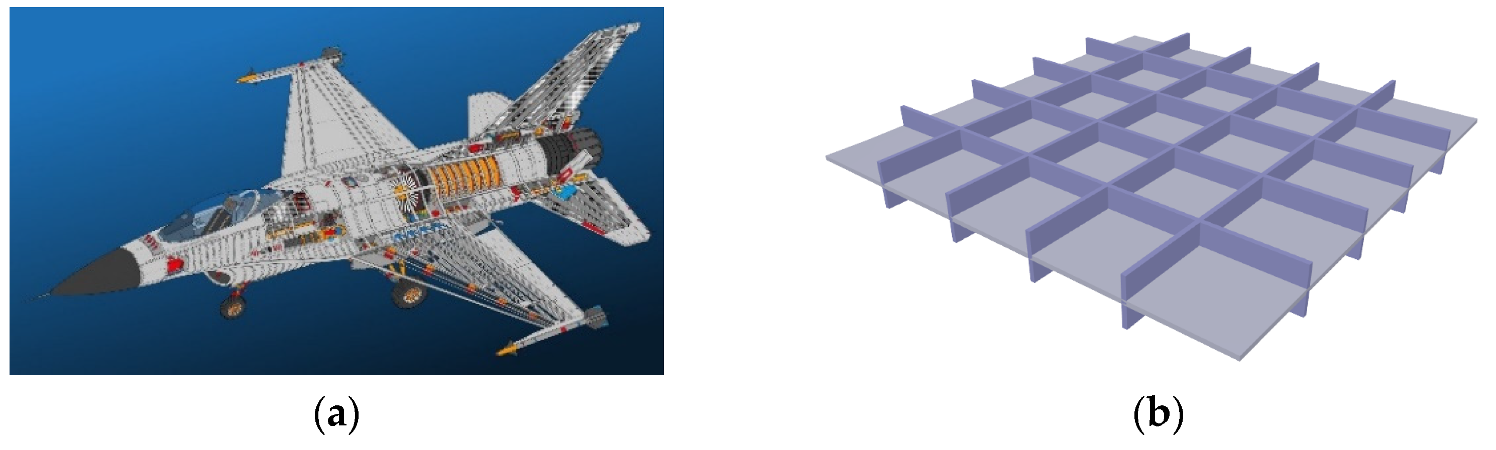
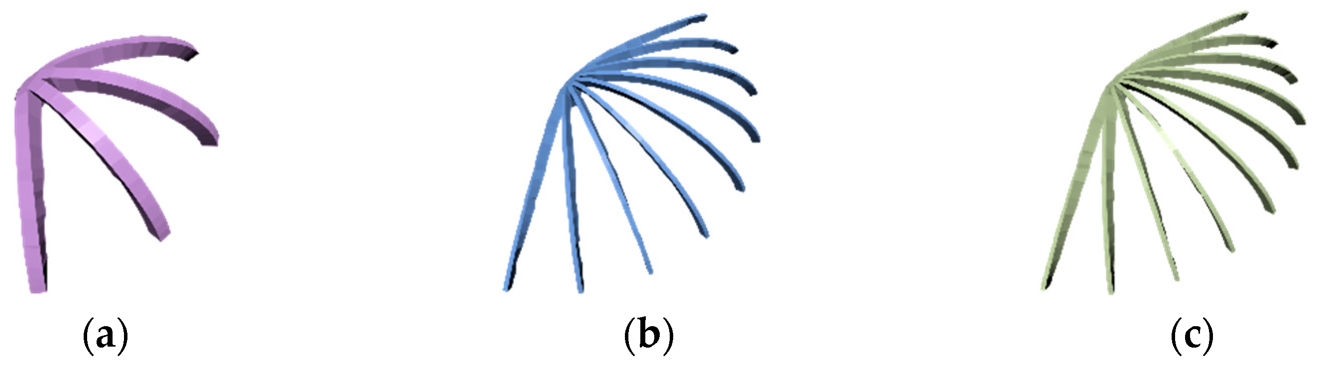
In addition to skin-frame and honeycomb-like structures, which can be found in many nature and man-made structures, stiffened structures, including stiffened plates and stiffened shells, are much more frequently seen in nature and engineering structures. Plant leaves (
Figure 1a), fly wings (
Figure 1b), and human rib–skin (
Figure 1c) are excellent examples found in nature and the human body that use stiffeners to support skin surfaces.
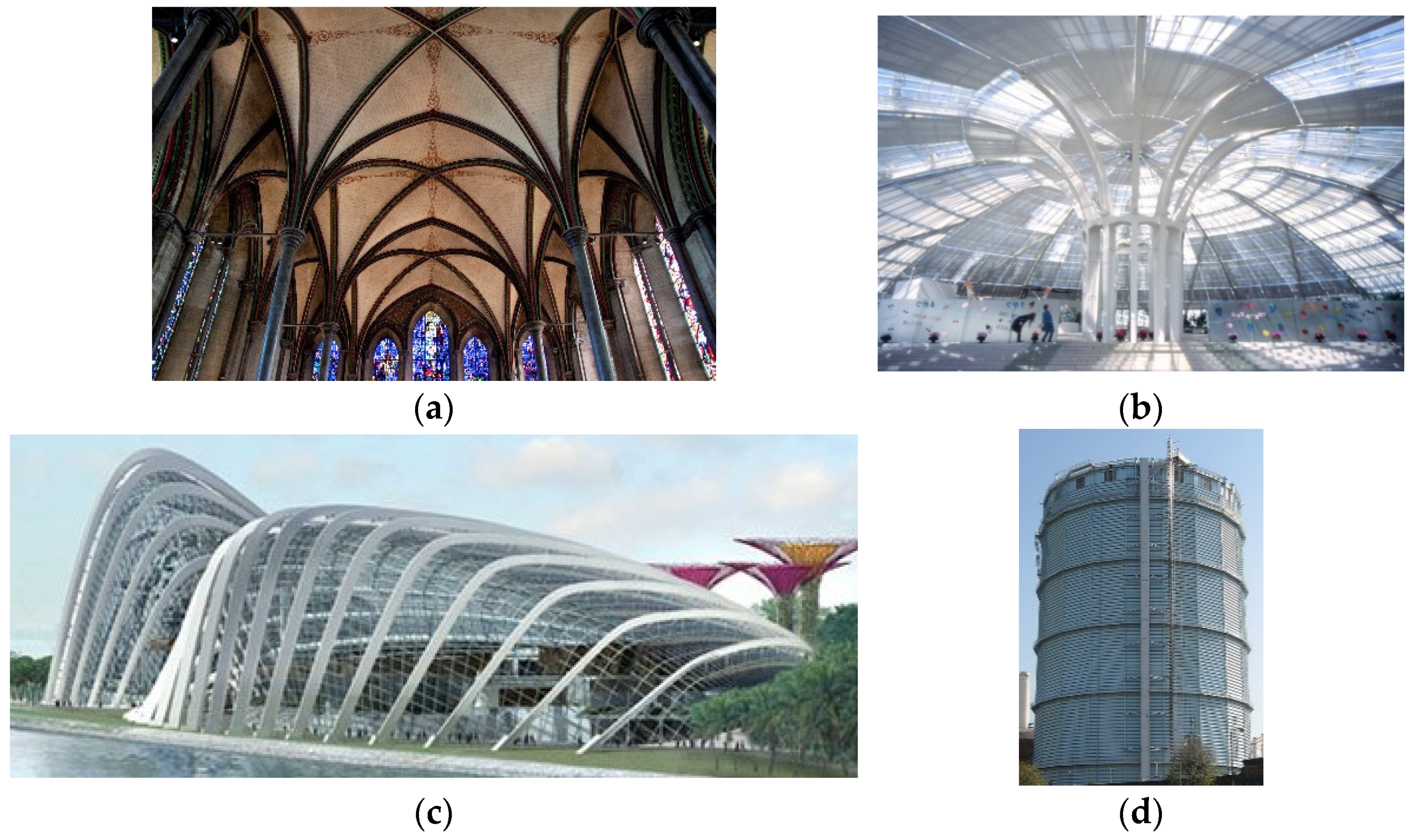
Apart from stiffened structures in nature, many engineering structures are stiffened to raise strength and stiffness and reduce material costs. These stiffened structures include buildings (
Figure 2a–c), and gas holders (
Figure 2d).
Stiffened structures can be divided into single- and double-sided structures. Single-sided stiffened structures have all of the stiffeners on one side of the skin’s surfaces (
Figure 3a). Double-sided stiffened structures have the stiffeners on both sides of the skin’s surfaces (
Figure 3b). Due to the requirement of aesthetics, 3D printed objects should be stiffened on one side. Therefore, we only investigated single-sided stiffened structures in this paper.
According to the distribution of stiffeners, stiffened structures can be divided into unidirectional, bidirectional, and arbitrary structures. Unidirectional structures are stiffened with stiffeners in one direction, bidirectional structures are stiffened with stiffeners in two different directions, and arbitrary structures are stiffened in any direction with straight or curved stiffeners.
The main functions of stiffeners are to increase the strength and stiffness and reduce material costs. In addition, well-designed stiffened structures can achieve aesthetic satisfaction. In addition to the above functions, stiffened structures have two advantages compared with skin-frame structures:
- (1)
The frames of skin-frame structures occupy a much larger space. In contrast, the space required by stiffened structures is much smaller, since all of the ribs are closely attached to the skin’s surfaces;
- (2)
Unlike skin-frame structures where only the ends of the truss members are in contact with the skin’s surfaces, leading to a small contact area and large stress concentrations between the frame and skin’s surface, stiffened structures have a much larger contact area to significantly reduce stress concentrations, since the inner faces of all stiffeners are in contact with the skin’s surface.
Compared to honeycomb-like structures, stiffened structures have the following benefits:
- (1)
Stiffened structures can place stiffeners on skin surfaces more efficiently and effectively, since the placing of stiffeners follows finite element calculation results of a hollow object. However, honeycomb-like interior structures carve porous cells following finite element calculation results of a solid object. The finite element calculation results of a solid object are completely different from the finite element calculation results of a hollow object to be made;
- (2)
The carved cells of honeycomb-like structures fill the whole volume. However, the stiffeners of stiffened structures only occupy a very small part of the whole volume. Therefore, stiffened structures can greatly reduce the volume over honeycomb-like interior structures;
- (3)
The internal space of honeycomb-like interior structures is fully occupied by the cells. Conversely, the internal space of stiffened structures is not occupied. Therefore, stiffened structures are especially suitable for situations where an unoccupied internal space is required.
In order to tackle the above problems, Li et al. [
4] used a rib-reinforced shell structure to release internal space and optimized the topology of the rib network. The work in [
4] did not consider structures stiffened using unidirectional and bidirectional stiffeners, which are most widely applied in engineering. In addition, [
4] placed stiffeners along the edges of finite elements, which applied a serious limitation on placing stiffeners in the most appropriate positions and directions to maximize the potential of the stiffeners. The current paper tackles these problems and makes the following contributions:
Introduces unidirectionally and bidirectionally stiffened structures that are widely applied in engineering into 3D printing of geometric models to effectively stiffen thin-walled 3D models for maximum strength and minimum material costs;
Investigates the finite element analysis of stiffened structures with stiffeners not on the edges of finite elements and performs finite element calculations of unidirectionally and bidirectionally stiffened 3D printed objects;
Integrates finite element calculations into optimization design and formulates the mathematical model of optimization design to minimize material costs and maximize the strength of 3D printed objects.
2. Related Work
The work proposed in this paper is related to 3D printing, finite element analysis, and structural optimization. We briefly review existing work on these aspects.
2.1. 3D Printing
3D printing has become an active research field and has attracted much research attention. There are many publications on the various aspects of 3D printing. In this subsection, we briefly review some of them.
Skouras et al. [
5] presented a method for combining finite element analysis, sparse regularization, and constrained optimization for fabrication-oriented design of actuated deformable characters. This allows a user to automatically create physically fabricated prototypes using rapid manufacturing technologies. Calì et al. [
6] designed an intuitive workflow that can automatically fit novel 3D printable and posable joints to a rigged 3D model with user specified rotational constraints. This method is able to convert 3D models into printable, articulated, and posable models with internal friction and without the need for manual assembly. Zhu et al. [
7] introduced a new method to synthesize mechanical toys from input motions. With designer supplied geometry and a time-varying motion, the algorithm automatically selects parts from a parameterized set and optimizes the positions and parameters for these parts; then, it generates a mechanism assembly to produce specified motion. Similarly, Coros et al. [
8] presented an interactive design system to design a wide range of animated mechanical characters that can be fabricated using 3D printing. The system takes an articulated character and user created motion curves as inputs and generates an optimized mechanism that approximates motion curves as closely as possible. To manufacture physical objects with the desired translucent appearance, Done et al. [
9] presented a complete solution for automatically fabricating a material volume with a desired surface bidirectional subsurface scattering reflectance distribution function. To overcome the problem of computing an object’s material composition from a functional description, Chen et al. [
10] provided a process called specification to fabrication translation. This process allows for 3D printing of complex objects with spatially varying appearance, optical characteristics, and mechanical properties.
2.2. Finite Element Analysis
Finite element analysis (FEA) originated from the need to solve complex elasticity and structural analysis problems in civil and aeronautical engineering. It has become the most effective numerical method widely applied in scientific research and engineering calculations. There are many publications on finite element analyses in these fields. Here, we only review some representative finite element analyses in engineering structures, especially focusing on plates and shells.
Zienkiewicz et al. [
11] introduced the finite element method for solid and structural mechanics. Rao et al. [
12] and Samanta and Mukhopadhyay [
13] investigated finite element analysis of stiffened plates and shells with large displacements, respectively. Samanta [
14] used FEA to analyze the vibrations of stiffened shells. Ojeda et al. [
15] developed a new approach for stiffened composite plates. Cui et al. [
16] presented a smoothed FEA to deal with geometrically linear and nonlinear problems of plates and shells. Nguyen-Van et al. [
17] considered mesh distortions in the FEA of plates and shells.
2.3. Structural Optimization
Structural optimization of 3D printing using a single material is an active topic. It has been investigated by some researchers.
To guarantee structurally sound prints that can survive cleaning, transportation, or handling, Stava et al. [
18] presented a system with automatic detection and correction. The areas with high structural stress are detected by combining a lightweight structural analysis solver with 3D medial axis approximations. The model is corrected by combining three approaches: hollowing, thickening, and strut insertion.
To fabricate shell objects with variable thicknesses, Zhao et al. [
19] presented a two-step technique to optimize thickness parameters according to the given boundary surface and user specified external forces. They first developed a patch-based simulation technique to efficiently support the static simulation. Afterwards, the derivative of the stress required in the sensitivity analysis was computed to turn the optimization into sequential linear programming.
For the purpose of reducing the cost of the materials used in 3D printing, Wang et al. [
2] proposed an automatic solution to design a skin-frame structure. The frame structure was designed by an optimization scheme that significantly reduces materials and guarantees that the optimized structure is physically stable, geometrically approximate, and printable. The number of struts is minimized by solving a sparsity optimization problem.
Similarly, Lu et al. [
3] introduced a hollowing optimization algorithm based on the concept of a honeycomb-cell structure to reduce the material of 3D models by carving porous cells in solids. The yielding honeycomb-like interior structure provides an optimal strength-to-weight ratio and relieves the overall stress.
Hollowing and thickening without internal supports release the internal space but it does not use materials optimally, since shell structures are weak in structural strength and stiffness. Skin-frame and honeycomb-like structures occupy the internal space that is to be used in many situations. To tackle the above problems, this paper used stiffened structures with unidirectional and bidirectional stiffeners, widely used in engineering, for 3D printing to release the internal space, investigated the finite element analysis to deal with stiffeners at arbitrary positions and in arbitrary orientations, which was not addressed in [
4], and carried out optimization design to improve structural strength and stiffness and minimize material consumption of single material 3D printing.
3. Finite Element Analysis
Zienkiewicz et al. [
20] presented a method to treat curved shells as an assembly of flat shell elements. This treatment enables us to analyze both curved and flat skin surfaces. We applied the same deformations at the junctions of stiffeners and skin surfaces so that the same displacement functions were applied to both beam and flat shell elements. There are two types of flat shell elements: the constant strain triangle (CST), which deals with in-plane deformations, and the discrete Kirchhoff triangle (DKT), which tackles the lateral bending deformations. The beam elements can be placed within the shell elements in any place with arbitrary orientations. The large deflection problem is addressed by applying the von Karman’s large deflection theory. An iterative procedure is introduced to solve the geometric nonlinearity. For the sake of completeness, this finite element analysis is introduced in the following subsections.
3.1. Flat Shell Element
The basic flat shell element employed here was a combination of CST and DKT elements.
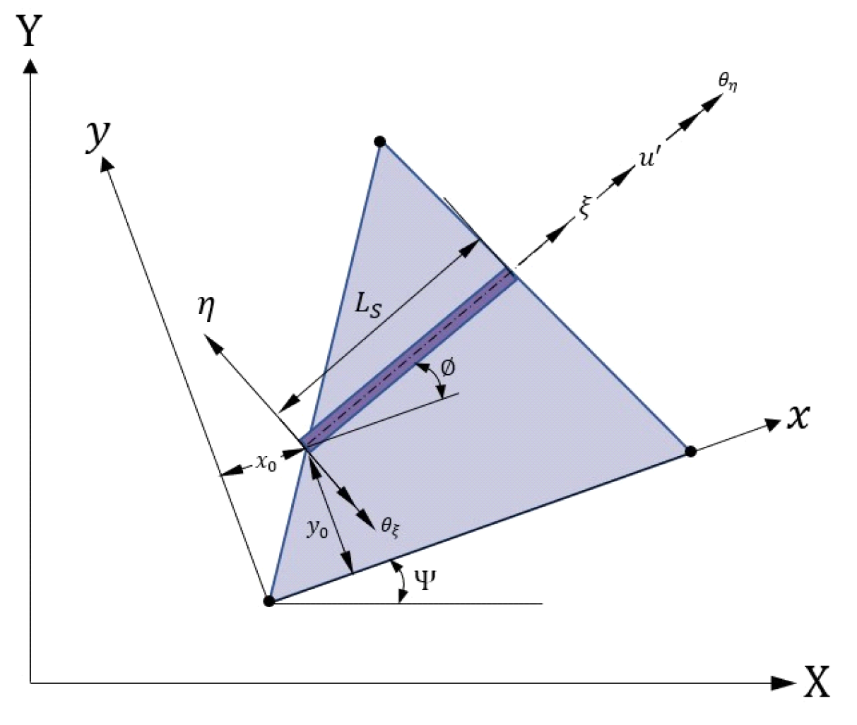
Figure 4 shows a typical triangular element. Its nodes are arranged in an anticlockwise direction. Each node contains two translational degrees of freedom. In
Figure 4, the X- and Y-axes define a global coordinate system,
x- and
y-axes define a local coordinate system, and the
ξ- and
η-axes define a skew coordinate system. The stiffness matrix of the element presented in [
21] can be written as:
where
denotes the element volume.
3.2. Finite Element Formulation of Stiffeners
The stiffeners considered in [
4] are on the edges of the flat shell finite elements. This limitation seriously prevents stiffeners from being placed at arbitrary positions and in arbitrary directions that cannot maximize the potential of stiffeners in stiffening shell structures. In this subsection, we considered placing stiffeners at any position and in any orientation to tackle general situations of arranging stiffeners so that the potential of stiffeners could be maximized.
We first present the element stiffness of the stiffener so that we can accumulate the contributions of stiffeners to skin surfaces. As shown in
Figure 4, the displacement field of the stiffener in the skew coordinate system has three translations and two rotations [
15]:
Let the middle plane of the shell be the reference plane for the stiffener, the coordinate transformation from the skew coordinates
to the local coordinates
is defined as:
Solving Equation (4) for
and
y, the following equation is obtained:
By applying same shape functions to both stiffener and flat shell elements, we can guarantee the deformation compatibility between these two elements. The local displacements of stiffeners can be represented in local displacements of flat shell elements as:
where
and
represent the displacements in the reference plane of the flat shell elements, and
and
are the rotations of the flat shell elements around the
and
-axes, respectively.
The generalized strain vector,
, in the
stiffener skew coordinate system:
can be transformed into that in the
shell elemental local coordinate system using the following transformation:
where
is the transformation matrix that relates the strain vector in the
stiffener skew coordinate system to that in the
shell elemental local coordinate system:
The strain vector,
, in the shell elemental local coordinate system can be defined as:
The strain vector,
, in the elemental local coordinate system can be related to the displacement vector,
, through the following strain–displacement relationship:
and the
matrix is given bellow:
where
and
The stress–strain relationship of the stiffener in the local coordinate system can be expressed as:
where
In Equations (15) and (16), is the axial force, is the bending moment, and is the torsion in the stiffener. is the Young’s modulus of the stiffener material, and is the cross-sectional area of the stiffener. and are the first and second moment of the stiffener’s cross-sectional area about the reference axis, respectively, denotes the modulus of rigidity, and denotes the polar moment of inertia of the stiffener’s cross-sectional area.
The element stiffness of the stiffener is given by:
Finally, the overall stiffness matrix for the stiffened structures can be calculated by adding individual stiffness from CST, DKT, and stiffener elements through the following equation:
4. Optimization Design
For 3D printed objects and structures, the wall-thickness of shell structures is usually set to the minimum printable wall thickness to reduce material consumption. The structural strength and stiffness are satisfied by stiffening shell structures with stiffeners. Since the wall-thickness of shell structures is the minimum printable thickness, minimizing the material consumption of 3D printed objects and structures becomes the minimization of the total volume of all stiffeners.
Stiffeners with different types of cross-sections are available in engineering applications. In this paper, stiffeners with rectangular cross-sections were used to demonstrate the optimization design model.
Let
w and
h represent the width and height of the stiffener cross-section. The goal was to minimize the overall volume of stiffeners while satisfy the strength requirement. The objective function for the optimization design can be formulated as finding the minimum of the total stiffener volume:
where
is the volume of the
stiffener;
is the total number of the stiffeners;
is the allowed maximum von Mises stress for both shell elements and stiffener elements;
is the material yield strength;
and
are the design variables; and
,
,
, and
are the lower and upper bounds of the stiffener width and height.
Several optimization methods, such as the genetic algorithm [
22,
23,
24] and particle swarm optimization [
25,
26,
27], can be used to solve the above minimization problem. In this paper, the nonlinear constrained problem formulated in Equation (19) was solved with the interior point method in the MATLAB Optimization Toolbox, where the gradients are estimated using finite differences. That approach aims to solve the constrained minimization through a sequence of approximate minimization problems [
28]. To that purpose, the interior point optimization algorithm takes the original constrained minimization problem in Equation (19) and converts it into a new system (20) where the inequality constraints are removed:
Let
, represents the five inequality constraints in Equation (19),
is a vector of slack variables,
, associated with the inequality constraints,
, and the scalar
is a multiplier (called barrier parameter) of the expression
as described in [
29]. Note that the boundedness of the expression
requires all
to be positive. Equation (20) is then solved iteratively through a series of Newton steps and conjugate gradient steps [
30,
31] as follows. At each iteration, the method selects one of the following steps:
A direct step in (
), also called a Newton step. In this step, the Karush–Kuhn–Tucker (KKT) equations
are solved, where
is the Lagrangian function described as:
and
= (
) is the Lagrange multiplier vector;
A conjugate gradient step which determines
and
in order to solve Equation (20). To this aim, the method considers a quadratic approximation using a trust region [
30]. The procedure uses an approximation around a given point
of the function
subjected to minimization by using a simpler function describing accurately the behavior of the target function in the neighborhood of such a point, called the trust region [
29]. Thus, if
denotes the radius of the trust region, the method solves the KKT equations:
through least squares to determine the Lagrange multipliers. Then, the algorithm minimizes the norm of linearized constraints inside the region of radius
(we refer the interested reader to [
29,
31] for details).
The value of the barrier parameter
is reduced after each iteration to enable the final value to converge to the target result [
31] (see also [
32]).
5. Numerical Examples and Experimental Results
The integrated finite element analysis and optimization design were implemented in MATLAB on a desktop PC with an Intel Xeon E5 CPU and 32 GB of memory. As the FEA was computationally expensive, the CST, DKT, and stiffener elements were implemented in C++ but compiled as MEX functions for speed reason.
The material for both shell and stiffeners is acrylonitrile butadiene styrene (ABS). The Young’s modulus (
, Poisson ratio (
, and yield strength (
of the shell and stiffener material, and the stiffener limiting dimensions
,
,
, and
are given in
Table 1.
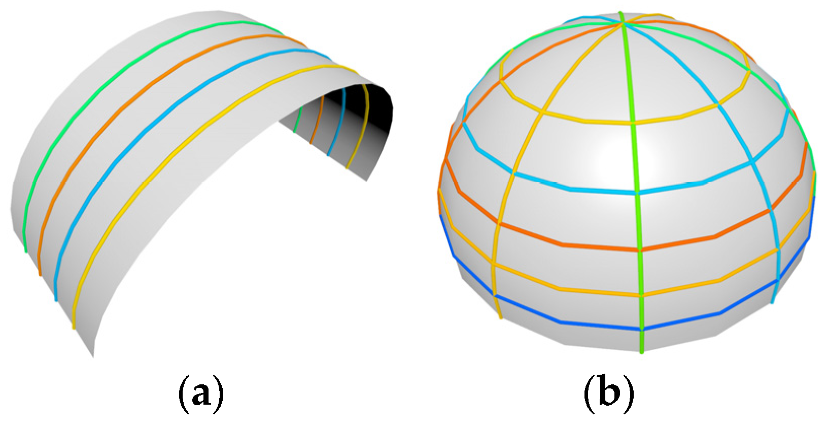
In this section, two stiffening methods are presented to place stiffeners along the skin. Unidirectional stiffeners mean that all the stiffeners go in the same direction (
Figure 5a), and bidirectional stiffeners mean the stiffeners go in two different directions (
Figure 5b).
Unidirectional stiffeners: Here, we discuss how to optimally stiffen a curved shell with unidirectional stiffeners.
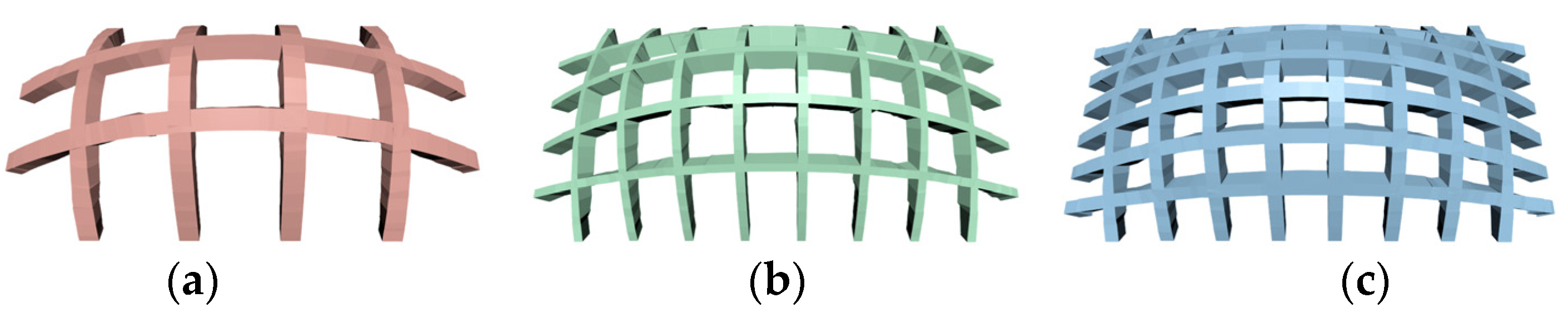
Figure 6 presents optimized supporting structures in the same radial direction. The total number and the total volume of the stiffeners for the optimized unidirectional stiffeners are shown in
Figure 6 and given in
Table 2, where (a) means
Figure 6a and
Figure 7a, (b) means
Figure 6b and
Figure 7b, and (c) means
Figure 6c and
Figure 7c. As shown in
Table 2,
Figure 6a has four stiffeners that reach the upper limits of the dimensions with a total volume of 3710.55
, but the stiffened shell still fails to satisfy the strength requirement.
Figure 6b has the best output within the feasible domain, which has a total volume of 1301.65
.
Figure 6c shows that more stiffeners are used than in
Figure 6b, and the total volume 1658.35
was slightly larger than
Figure 6b.
Bidirectional stiffeners: To find out the balance between maintaining object soundness and reducing printing material, all possible combinations of stiffeners in orthogonal directions are iterated to search for an optimized result.
Figure 7 presents some of the optimized results with different numbers of stiffeners. The total number and the total volume of the stiffeners for the optimized bidirectional stiffeners shown in
Figure 7 are given in
Table 2. For the case shown in
Figure 7a, fewer stiffeners were used in both directions leading to a smaller volume of stiffeners, 7068.91
. However, the stress constraint
could not be satisfied even when the size of the stiffeners reached the upper limits of the dimensions.
Figure 7b was the best output from the algorithm with a total volume of 6780.97
. In
Figure 7c, though the stress constraint was satisfied, the use of more stiffeners caused the largest total volume of 7200.96
.
3D Printed Uni- and Bidirectionally Stiffened Objects
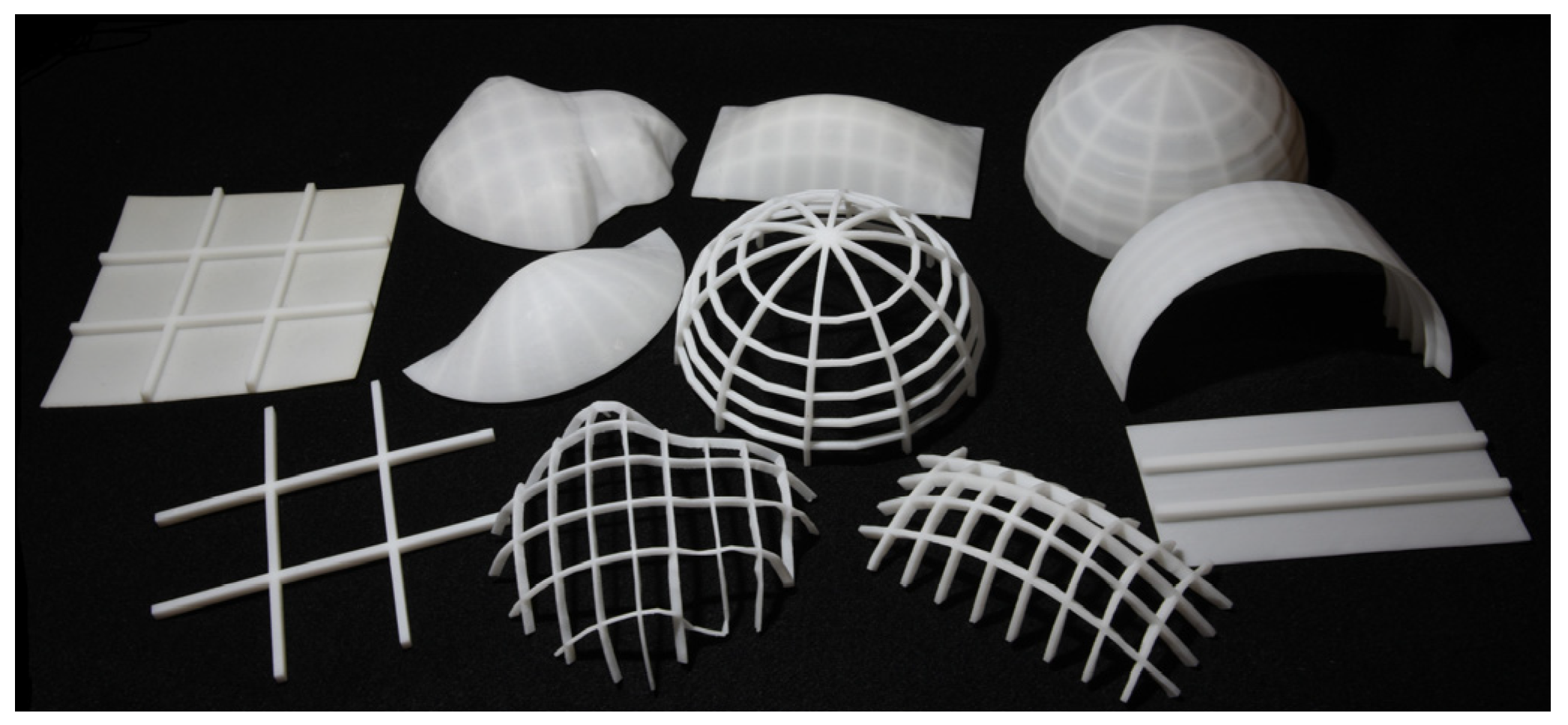
Figure 8 shows all 3D printed models obtained with the proposed optimization algorithm for uni- and bidirectionally stiffened objects. In
Figure 9,
Figure 10,
Figure 11,
Figure 12,
Figure 13,
Figure 14 and
Figure 15, boundaries are indicated with small purple spheres in (a). The applied load was gravity acting in the direction perpendicular to the plane defined by the boundaries (
Figure 10,
Figure 11,
Figure 12,
Figure 13,
Figure 14 and
Figure 15) or the plate plane (
Figure 9). Clamped supports were used for all the models shown in
Figure 9,
Figure 10,
Figure 11,
Figure 12,
Figure 13,
Figure 14 and
Figure 15.
Figure 9,
Figure 10,
Figure 11,
Figure 12,
Figure 13,
Figure 14 and
Figure 15 show the change in the stress field of these objects with and without optimized stiffeners. The total volume of stiffeners and the maximum von Mises stress in the shell of the models shown in
Figure 9,
Figure 10,
Figure 11,
Figure 12,
Figure 13,
Figure 14 and
Figure 15 are given in
Table 3.
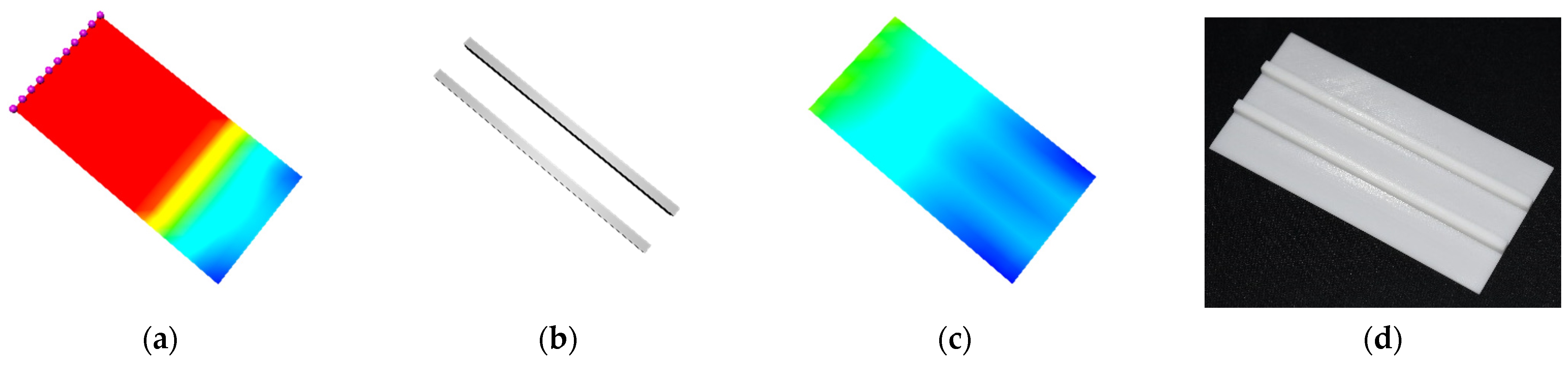
Figure 9 shows the stress field, optimized stiffeners, and 3D printed unidirectionally stiffened plate. As shown in
Table 3, the initial stress distribution of the flat plate without the unidirectional stiffeners, the maximum von Mises stress was 278.198 MPa, but after introducing two optimized unidirectional stiffeners with a total volume of 338.530
(
Figure 9b), the maximum von Mises stress reduced noticeably from 278.198 MPa (
Figure 9a) to 22.977 MPa (
Figure 9c). The 3D printed model of the stiffened plate is shown in
Figure 9d.
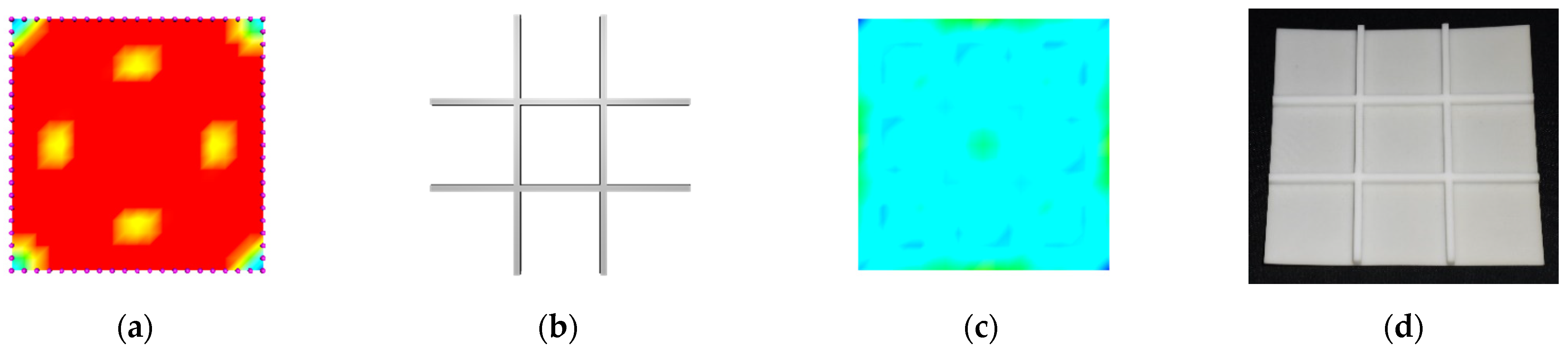
Figure 10 shows the stress field, optimized stiffeners, and 3D printed bidirectionally stiffened square plate. As shown in
Table 3, with the optimized stiffeners of volume 481.623
depicted in
Figure 10b, the initial maximum von Mises stress reduced from 159.268 MPa (
Figure 10a) to 21.749 MPa (
Figure 10c).
Figure 10d presents the 3D printed model.
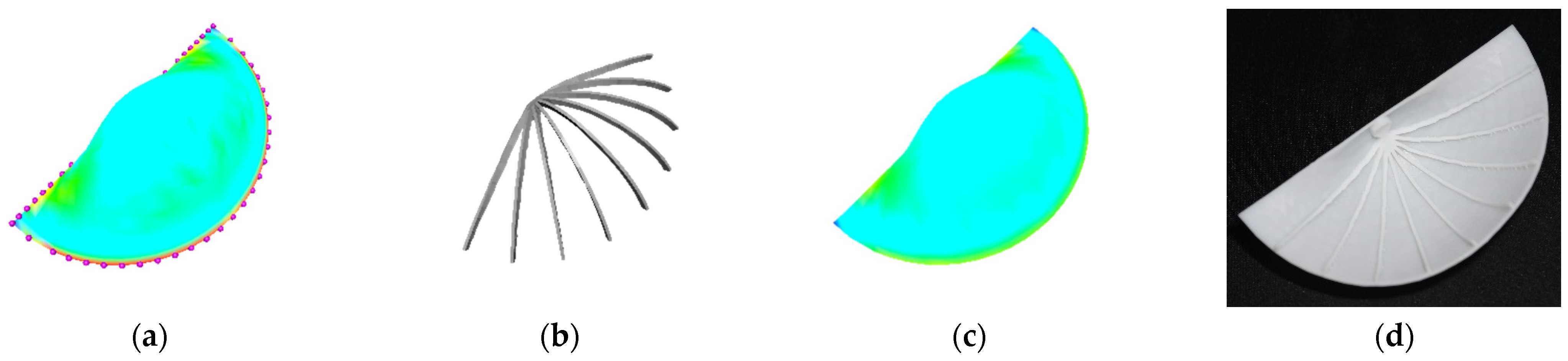
Another example of a unidirectionally stiffened snail is presented in
Figure 11.
Figure 11a shows that the initial maximum von Mises stress in the snail without any stiffener was 33.273 MPa. As shown in
Table 3, after adding supporting stiffeners with a volume of 141.645
(
Figure 11b), the maximum von Mises stress in the snail dropped from 33.273 MPa (
Figure 11a) to 27.282 MPa (
Figure 11c), and
Figure 11d shows the 3D printed model.
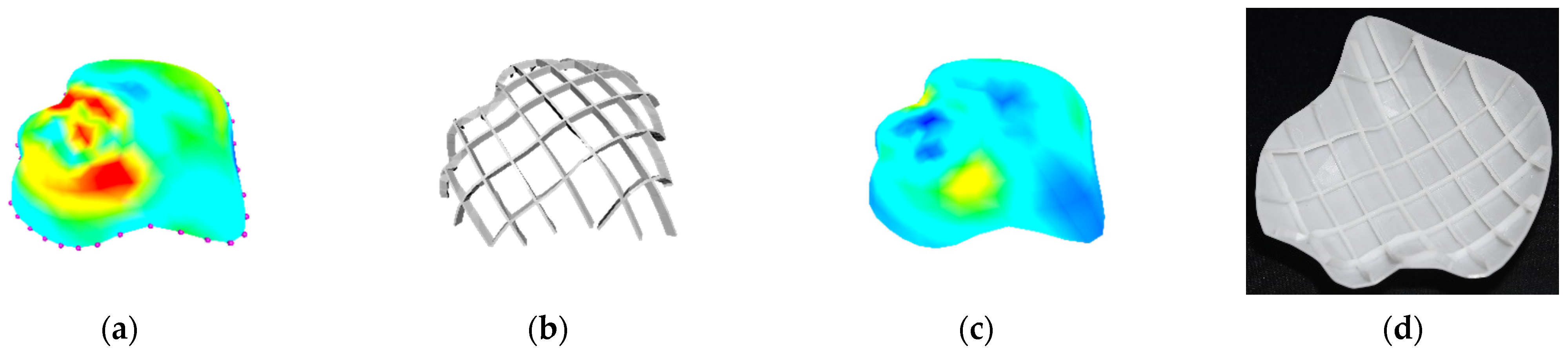
Figure 12 presents the application of bidirectional stiffeners in a more complicated geometry botanic. As shown in
Table 3, the initial stress without bidirectional stiffeners had a maximum value of 90.927 MPa (
Figure 12a). The introduction of stiffening structures with a volume of 346.926
(
Figure 12b) reduced the stress from 90.927 MPa to 38.604 MPa (
Figure 12c), and
Figure 12d shows the 3D printed model.
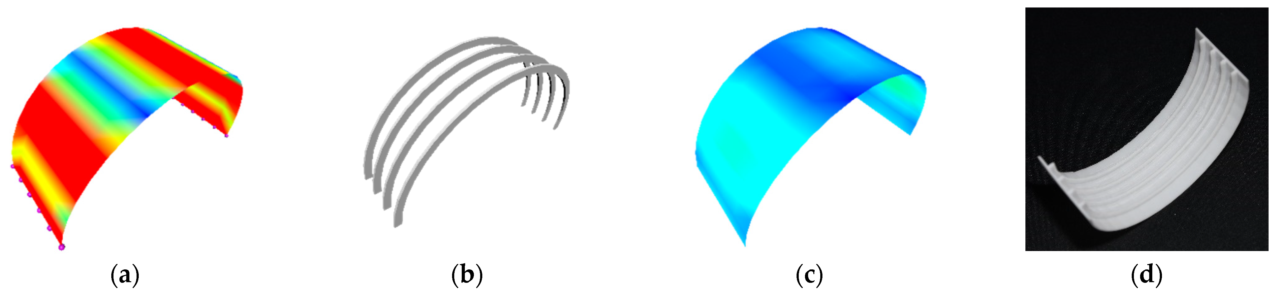
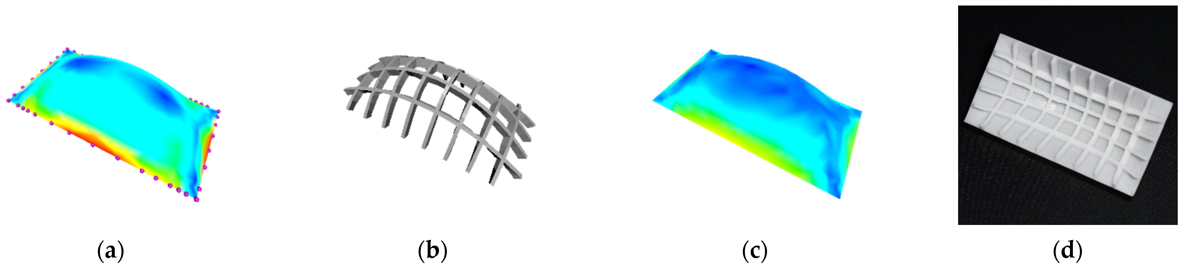
The calculated results of the arch bridge are presented in
Figure 13 and
Table 3. With the optimized stiffeners with a volume of 281.855
(
Figure 13b), the maximum von Mises stress in the arch bridge reduced from 94.498 MPa (
Figure 13a) to 15.785 MPa (
Figure 13c), and
Figure 13d shows the 3D printed model.
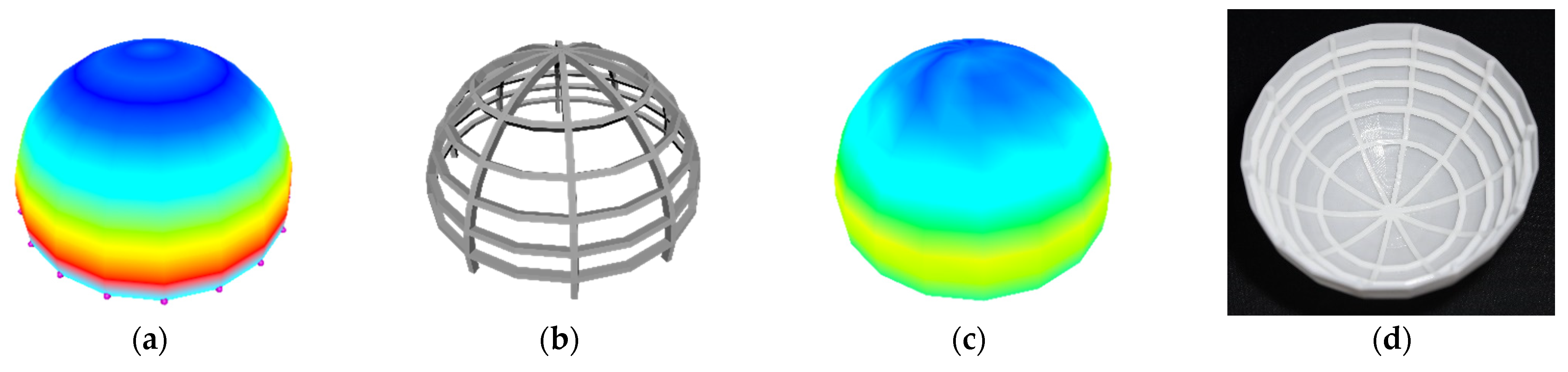
The calculated results of the dome are presented in
Figure 14 and
Table 3.
Figure 14a shows that the initial maximum von Mises stress in the dome without any stiffener was 59.028 MPa. After inserting the supporting structures with a volume of 689.206
(
Figure 14b), the maximum von Mises stress in the dome dropped from 59.028 MPa (
Figure 14a) to 35.631 MPa (
Figure 14c), and
Figure 14d shows the 3D printed model.
The calculated results of the hemisphere are presented in
Figure 15 and
Table 3. The maximum von Mises stress of the initial stress field depicted in
Figure 15a without bidirectional stiffeners was 42.020 MPa.
Figure 15b shows the optimized bidirectional stiffeners with a volume of 989.145
. With the optimized stiffeners, the maximum von Mises stress became 36.690 MPa (
Figure 15c), and
Figure 15d shows the 3D printed model.
6. Conclusions and Limitations
In this paper, unidirectionally and bidirectionally stiffened structures were introduced to stiffen 3D printed objects for saving material costs and improving structural strength and stiffness. The finite element analysis of stiffened objects with stiffeners placed in arbitrary positions and directions was investigated. The optimization of stiffened objects was examined. They were integrated to minimize material consumption. Numerical examples demonstrated obvious improvements brought about by the proposed approach.
The proposed approach sliced geometries equally to the placed stiffeners. The stress field was not considered when placing stiffeners. Therefore, the distribution of stiffeners may not have been optimal. A possible improvement is to find an oriented bounding box of the areas exceeding the specified stress and to slice the geometry within these critical areas. Alternatively, we could place stiffeners under the guidance of the stress field. The distribution optimization and cross-section size optimization of the stiffeners will be integrated into a unified model to further minimize material consumption of 3D printing. The stiffeners with other types of cross-sectional shapes were not examined in this paper. Their performance in stiffening thin-walled objects can be investigated and optimized to save material costs and improve structural strength and stiffness
An improved topology optimization in the future is to dimension each stiffener independently and exclude some of the stiffeners which have dimensions that reach the lower bound. After a stiffener network is generated, we will run the cross-sectional shape optimization to identify stiffeners that have dimensions that are at the minimum bound. We will then remove one of these identified stiffeners that has the least effect on the network to generate a new stiffener network and repeat the shape optimization on this new network. The process will be repeated until an optimal stiffener distribution and optimal stiffener size, which satisfy all constraints, are obtained.
Author Contributions
Conceptualization, A.Z. and L.Y.; Formal analysis, A.Z. and Z.Z.; Funding acquisition, J.C.; Investigation, A.Z.; Methodology, A.Z.; Resources, H.H.; Supervision, J.C., H.H., A.I., L.Y. and J.Z.; Validation, A.Z. and S.B.; Writing—original draft, A.Z.; Writing—review and editing, A.I. and J.Z. All authors have read and agreed to the published version of the manuscript.
Funding
This research was supported by the PDE-GIR project which received funding from the European Union Horizon 2020 Research and Innovation Programme under the Marie Skodowska–Curie grant agreement No. 778035. A.I. thanks the project TIN2017-89275-R funded by MCIN/AEI/10.13039/501100011033/ FEDER “Una manera de hacer Europa”.
Conflicts of Interest
The authors declare no conflict of interest.
References
- Wang, W.; Liu, Y.-J.; Wu, J.; Tian, S.; Wang, C.C.L.; Liu, L.; Liu, X. Support-Free Hollowing. IEEE Trans. Vis. Comput. Graph. 2018, 24, 2787–2798. [Google Scholar] [CrossRef] [PubMed] [Green Version]
- Wang, W.; Wang, T.Y.; Yang, Z.; Liu, L.; Tong, X.; Tong, W.; Deng, J.; Chen, F.; Liu, X. Cost-effective printing of 3D objects with skin-frame structures. ACM Trans. Graph. 2013, 32, 177. [Google Scholar] [CrossRef] [Green Version]
- Lu, L.; Chen, B.; Sharf, A.; Zhao, H.; Wei, Y.; Fan, Q.; Chen, X.; Savoye, Y.; Tu, C.; Cohen-Or, D. Build-to-last: Strength to weight 3D printed objects. ACM Trans. Graph. 2014, 33, 97. [Google Scholar] [CrossRef]
- Li, W.; Zheng, A.; You, L.H.; Yang, X.S.; Zhang, J.J.; Liu, L. Rib-reinforced shell structure. Comput. Graph. Forum 2017, 36, 15–27. [Google Scholar] [CrossRef] [Green Version]
- Skouras, M.; Thomaszewski, B.; Coros, S.; Bickel, B.; Gross, M. Computational design of actuated deformable characters. ACM Trans. Graph. 2013, 32, 82. [Google Scholar] [CrossRef]
- Calì, J.; Calian, D.; Amati, C.; Kleinberger, R.; Steed, A.; Kautz, J.; Weyrich, T. 3D-printing of non-assembly, articulated models. ACM Trans. Graph. 2012, 31, 1–8. [Google Scholar] [CrossRef]
- Zhu, L.; Xu, W.; Snyder, J.; Liu, Y.; Wang, G.; Guo, B. Motion-guided mechanical toy modeling. ACM Trans. Graph. 2012, 31, 1–10. [Google Scholar] [CrossRef]
- Coros, S.; Thomaszewski, B.; Noris, G.; Sueda, S.; Forberg, M.; Sumner, R.W.; Matusik, W.; Bickel, B. Computational design of mechanical characters. ACM Trans. Graph. 2013, 32, 1–12. [Google Scholar] [CrossRef] [Green Version]
- Dong, Y.; Wang, J.; Pellacini, F.; Tong, X.; Guo, B. Fabricating spatially-varying subsurface scattering. ACM Trans. Graph. 2010, 29, 1–10. [Google Scholar]
- Chen, D.; Levin, D.I.W.; Didyk, P.; Sitthi-Amorn, P.; Matusik, W. Spec2fab: A reducer-tuner model for translating specifications to 3D prints. ACM Trans. Graph. 2013, 32, 135. [Google Scholar] [CrossRef] [Green Version]
- Zienkiewicz, O.; Taylor, R.; Fox, D. The Finite Element Method for Solid and Structural Mechanics, 7th ed.; Elsevier BV: Amsterdam, The Netherlands, 2014. [Google Scholar]
- Rao, D.V.; Sheikh, A.H.; Mukhopadhyay, M. A finite element large displacement analysis of stiffened plates. Comput. Struct. 1993, 47, 987–993. [Google Scholar] [CrossRef]
- Samanta, A.; Mukhopadhyay, M. Finite element large deflection static analysis of shallow and deep stiffened shells. Finite Elem. Anal. Des. 1999, 33, 187–208. [Google Scholar] [CrossRef]
- Samanta, A.; Mukhopadhyay, M. Free vibration analysis of stiffened shells by the finite element technique. Eur. J. Mech. A/Solids 2004, 23, 159–179. [Google Scholar] [CrossRef]
- Ojeda, R.; Prusty, B.G.; Lawrence, N.; Thomas, G. A new approach for the large deflection finite element analysis of isotropic and composite plates with arbitrary orientated stiffeners. Finite Elem. Anal. Des. 2007, 43, 989–1002. [Google Scholar] [CrossRef]
- Cui, X.Y.; Liu, G.R.; Li, G.Y.; Zhao, X.; Nguyen-Thoi, T.; Sun, G.Y. A smoothed finite element method (SFEM) for linear and geometrically nonlinear analysis of plates and shells. Comput. Modeling Eng. Sci. 2008, 28, 109–125. [Google Scholar]
- Nguyen-Van, H.; Nguyen-Hoai, N.; Chau-Dinh, T.; Tran-Cong, T. Large deflection analysis of plates and cylindrical shells by an efficient four-node flat element with mesh distortions. Acta Mech. 2015, 226, 2693–2713. [Google Scholar] [CrossRef]
- Stava, O.; Vanek, J.; Benes, B.; Carr, N.; Mĕch, R. Stress relief: Improving structural strength of 3D printable objects. ACM Trans. Graph. 2012, 31, 1–11. [Google Scholar] [CrossRef]
- Zhao, H.; Xu, W.; Zhou, K.; Yang, Y.; Jin, X.; Wu, H. Stress-constrained thickness optimization for shell object fabrication. Comput. Graph. Forum 2017, 36, 368–380. [Google Scholar] [CrossRef]
- Zienkiewicz, O.C.; Morgan, K. Finite Elements and Approximation; Dover Publications: New York, NY, USA, 2006. [Google Scholar]
- Rao, S.S. The Finite Element Method in Engineering, 5th ed.; Butterworth Heinemann: Oxford, UK, 2010. [Google Scholar]
- Gálvez, A.; Iglesias, A.; Puig-Pey, J. Iterative two-step genetic-algorithm-based method for efficient polynomial B-spline surface reconstruction. Inf. Sci. 2012, 182, 56–76. [Google Scholar] [CrossRef]
- Wang, S.; Xia, Y.; Wang, R.; You, L.H.; Zhang, J.J. Optimal NURBS conversion of PDE surface-represented high-speed train heads. Optim. Eng. 2019, 20, 907–928. [Google Scholar] [CrossRef] [Green Version]
- Hu, S.; Liu, H.; Wu, X.; Li, R.; Zhou, J.; Wang, J. A Hybrid Framework Combining Genetic Algorithm with Iterated Local Search for the Dominating Tree Problem. Mathematics 2019, 7, 359. [Google Scholar] [CrossRef] [Green Version]
- Družeta, S.; Ivić, S.; Grbčić, L.; Lučin, I. Introducing languid particle dynamics to a selection of PSO variants. Egypt. Inform. J. 2020, 21, 119–129. [Google Scholar] [CrossRef]
- Gálvez, A.; Iglesias, A. Efficient particle swarm optimization approach for data fitting with free knot B-splines. Comput.-Aided Des. 2011, 43, 1683–1692. [Google Scholar] [CrossRef]
- Fan, S.-K.S.; Jen, C.-H. An Enhanced Partial Search to Particle Swarm Optimization for Unconstrained Optimization. Mathematics 2019, 7, 357. [Google Scholar] [CrossRef] [Green Version]
- Byrd, R.H.; Hribar, M.E.; Nocedal, J. An Interior Point Algorithm for Large-Scale Nonlinear Programming. SIAM J. Optim. 1999, 9, 877–900. [Google Scholar] [CrossRef]
- Byrd, R.H.; Gilbert, J.C.; Nocedal, J. A Trust Region Method Based on Interior Point Techniques for Nonlinear Programming. Math. Program. 2000, 89, 149–185. [Google Scholar] [CrossRef] [Green Version]
- Steihaug, T. The Conjugate Gradient Method and Trust Regions in Large Scale Optimization. SIAM J. Numeical Anal. 1983, 20, 626–637. [Google Scholar] [CrossRef] [Green Version]
- Waltz, R.A.; Morales, J.L.; Nocedal, J.; Orban, D. An interior algorithm for nonlinear optimization that combines line search and trust region steps. Math. Program. 2006, 107, 391–408. [Google Scholar] [CrossRef]
- Ugail, H.; Aggarwal, R.; Iglesias, A.; Howard, N.; Campuzano, A.; Su´arez, P.; Maqsood, M.; Aadil, F.; Mehmood, I.; Gleghorn, S.; et al. Social distancing enhanced automated optimal design of physical spaces in the wake of the COVID-19 pandemic. Sustain. Cities Soc. 2021, 68, 102791. [Google Scholar] [CrossRef]
Figure 4.
Local coordinate system of a stiffener within a flat shell element.
Figure 4.
Local coordinate system of a stiffener within a flat shell element.
Figure 5.
Two ways of slicing of geometries: (a) unidirectional slicing; (b) bidirectional slicing.
Figure 5.
Two ways of slicing of geometries: (a) unidirectional slicing; (b) bidirectional slicing.
Figure 6.
Optimized unidirectional stiffeners from the algorithm: (a) 4 stiffeners; (b) 9 stiffeners; (c) 10 stiffeners.
Figure 6.
Optimized unidirectional stiffeners from the algorithm: (a) 4 stiffeners; (b) 9 stiffeners; (c) 10 stiffeners.
Figure 7.
Optimized bidirectional stiffeners from the algorithm: (a) 6 stiffeners; (b) 12 stiffeners and (c) 14 stiffeners.
Figure 7.
Optimized bidirectional stiffeners from the algorithm: (a) 6 stiffeners; (b) 12 stiffeners and (c) 14 stiffeners.
Figure 8.
All of the 3D printed models.
Figure 8.
All of the 3D printed models.
Figure 9.
Unidirectionally stiffened flat plate, from left to right: (a) initial stress without stiffeners; (b) optimized stiffeners; (c) final stress with stiffeners; (d) 3D print.
Figure 9.
Unidirectionally stiffened flat plate, from left to right: (a) initial stress without stiffeners; (b) optimized stiffeners; (c) final stress with stiffeners; (d) 3D print.
Figure 10.
Bidirectionally stiffened square plate, from left to right: (a) initial stress without stiffeners; (b) optimized stiffeners; (c) final stress with stiffeners; (d) 3D print.
Figure 10.
Bidirectionally stiffened square plate, from left to right: (a) initial stress without stiffeners; (b) optimized stiffeners; (c) final stress with stiffeners; (d) 3D print.
Figure 11.
Unidirectionally stiffened snail, from left to right: (a) initial stress without stiffeners; (b) optimized stiffeners; (c) final stress with stiffeners; (d) 3D print.
Figure 11.
Unidirectionally stiffened snail, from left to right: (a) initial stress without stiffeners; (b) optimized stiffeners; (c) final stress with stiffeners; (d) 3D print.
Figure 12.
Bidirectionally stiffened botanic, from left to right: (a) initial stress without stiffeners, (b) optimized stiffeners, (c) final stress with stiffeners, (d) 3D print.
Figure 12.
Bidirectionally stiffened botanic, from left to right: (a) initial stress without stiffeners, (b) optimized stiffeners, (c) final stress with stiffeners, (d) 3D print.
Figure 13.
Unidirectionally stiffened arch bridge, from left to right: (a) initial stress without stiffeners; (b) optimized stiffeners; (c) final stress with stiffeners; (d) 3D print.
Figure 13.
Unidirectionally stiffened arch bridge, from left to right: (a) initial stress without stiffeners; (b) optimized stiffeners; (c) final stress with stiffeners; (d) 3D print.
Figure 14.
Bidirectionally stiffened dome, from left to right: (a) initial stress without stiffeners; (b) optimized stiffeners; (c) final stress with stiffeners; (d) 3D print.
Figure 14.
Bidirectionally stiffened dome, from left to right: (a) initial stress without stiffeners; (b) optimized stiffeners; (c) final stress with stiffeners; (d) 3D print.
Figure 15.
Bidirectionally stiffened hemisphere, from left to right: (a) initial stress without stiffeners; (b) optimized stiffeners; (c) final stress with stiffeners; (d) 3D print.
Figure 15.
Bidirectionally stiffened hemisphere, from left to right: (a) initial stress without stiffeners; (b) optimized stiffeners; (c) final stress with stiffeners; (d) 3D print.
Table 1.
Material properties and stiffener limiting dimensions.
Table 1.
Material properties and stiffener limiting dimensions.
| (MPa) | | (MPa) | (mm) | (mm) | (mm) | (mm) |
|---|
| 2000.0 | 0.3 | 40.0 | 1.0 | 4.0 | 1.0 | 4.0 |
Table 2.
Stiffener number and volume.
Table 2.
Stiffener number and volume.
| | (a) | (b) | (c) |
|---|
| | NoS * | VoS ** (mm3) | NoS * | VoS ** (mm3) | NoS * | VoS ** (mm3) |
|---|
| Figure 6 | 4 | 3710.55 | 9 | 1301.65 | 10 | 1658.35 |
| Figure 7 | 6 | 7068.91 | 12 | 6780.97 | 14 | 7200.96 |
Table 3.
Total stiffener volume and maximum von Mises stress in the shells with and without stiffening.
Table 3.
Total stiffener volume and maximum von Mises stress in the shells with and without stiffening.
| | | Maximum von Mises Stress without Stiffening (MPa) | Maximum von Mises Stress with Stiffening (MPa) | Total Stiffener Volume (mm3) |
|---|
| Figure 9 | Flat plate | 278.198 | 22.977 | 338.530 |
| Figure 10 | Square plate | 159.268 | 21.749 | 481.623 |
| Figure 11 | Snail | 33.273 | 27.282 | 141.645 |
| Figure 12 | Botanic | 90.927 | 38.604 | 346.926 |
| Figure 13 | Bridge | 94.498 | 15.785 | 281.855 |
| Figure 14 | Dome | 59.028 | 35.631 | 689.206 |
| Figure 15 | Hemisphere | 42.020 | 36.690 | 989.145 |
| Publisher’s Note: MDPI stays neutral with regard to jurisdictional claims in published maps and institutional affiliations. |
© 2021 by the authors. Licensee MDPI, Basel, Switzerland. This article is an open access article distributed under the terms and conditions of the Creative Commons Attribution (CC BY) license (https://creativecommons.org/licenses/by/4.0/).


 ,
, 


