1. Introduction
Cold roll forming (CRF) is a continuous bending operation during which a long strip of metal is passed through consecutive sets of rolls, each performing only an incremental part of the bend until the desired cross-section profile is obtained [
1]. At present, the main research methods of roll forming are the analytical method, finite element method and finite strip method [
2]. In the early days, the main research method used by experts and scholars is the analytical method, and with the rapid development of computer technology, the computing speed has significantly improved, the finite element method and finite strip method have been the mainstream approach to the process of the roll forming. The meshless method is a new numerical method developed after the finite element method [
3,
4,
5,
6]. Heislita [
7] simulated the cold roll forming process with a 3-dimension (3D) finite element method (FEM) code PAM-STAMP. Brunet [
8] simulated the process with a combined 2D and 3D FEM code. Han [
9,
10,
11,
12] studied the cold roll forming process of a channel section, welded pipes, a thick channel section and a channel section with the outer edge with the spline finite strip method (SFSM). Liu [
13] used MARC to study the forming of high-strength steel cold forming. However, the finite element method and finite strip method are still faced with the problem of excessive computation time. Cheng [
14,
15,
16,
17,
18,
19] proposed a fast method for solving 3D problems. For the technology of cold roll forming, the main defects are edge waves, folds and so on, and these types of defects arise mainly due to the large longitudinal strain. Before numerical methods were applied to the rolling in the 1980s, engineers calculated the roll forming parameters relying on experiences and some of the existing glancing analytical methods. The basic idea of these analytical methods is calculating the elongation of longitudinal fiber to predict the forming process. Angel [
20] proposed the linear deformation model. Firstly, connect the corresponding points of two adjacent roll passes using straight lines, and then calculate the elongation of the line and the distance of the two racks. Bhattacharyya et al. [
21] calculated the length of deformation in a transition zone and used the length of a transition zone to calculate the elongation, but the length of this smooth transition needs the experimental device or experiences to determine, and the actual process is very complicated. Nakajima and Miznutani [
22] proposed a model of longitudinal strain and gave an approximate formula to calculate the longitudinal strain. Walker and Pick [
23,
24] used the cubic B spline function to fit the whole surface, and the longitudinal strain they defined is
Zhang [
25] utilized the updated Lagrangian method of elastic-plastic large-deformation spline finite strip method to analyze cold-rolled forming and deal with boundary conditions, and Zhang [
26] combined theoretical formulas and new analytical models on the previous basis to simulate the pipe forming process.
In recent years, roll forming technology has been developed rapidly and widely used in the manufacturing field. Therefore, the defects caused by the longitudinal strain in the roll forming process have become a research hotspot. JOO et al. [
27] studied the flexible roll forming process of variable cross-section profiles and analyzed the effect of geometrical parameters such as base section width, side wall height and flange width on the longitudinal strain. Woo et al. [
28] used FEM simulation and experiment to study the influence of profile flange length on the transverse distribution of longitudinal strain in flexible roll forming, and the result showed that the longitudinal strain and longitudinal bow decrease with increasing flange length for a trapezoid and a concave blank. Abeyrathna et al. [
29] researched the effect of process and part shape parameters on the peak longitudinal edge strain, longitudinal bow and spring back for three different advanced high-strength steel (AHSS) and Ultra High Strength Steel (UHSS) commonly used in automotive manufacturing. Liu et al. [
30] proposed a mathematical model to predict the bend angle distribution and longitudinal strain development in the deformation process. Sun et al. [
31] took the chain-die forming as the research object, studied permanent longitudinal strain and the web-warping in the forming process. Rezaei [
32] used Abaqus software to perform finite element simulation, obtained longitudinal edge strain and web warpage in the transition zone, and calculated the edge longitudinal strain in this zone. Wang [
33] showed that the necessary condition for longitudinal bending deformation is the linear distribution of longitudinal fibers. Su [
34,
35] studied the roll forming process and springback based on a five-boundary condition-forming angle distribution function and analyzed the effects of plate thickness, forming angle and material yield strength on stress, strain and springback angle.
The above analytical methods have played a very important role in calculating the roll forming parameters, but there are some problems to solve. One of the problems is that the track of the formation between corresponding points cannot be scientifically fitted. The parameters of cold roll forming cannot be well designed. The spline function works well when it stimulates the small deflection curve. For the large deflection curve, the result is poor, and for the multi-valued curve, it cannot be applied. In this paper, a new cubic spline function with the parameters of cumulative chords is presented. This function is selected as the fitting function to fit the track of the formation. This method can calculate the mean longitudinal strain of strip steel more accurately. The analytical method based on the mean longitudinal strain proposed can give fast analysis for different deformation angles and different rack spacing, which can be used as an important reference before numerical simulation to speed up the optimization of numerical simulation parameters.
2. Problem Statement
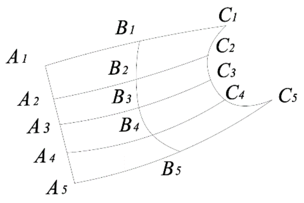
Roll forming is a process in which the strip steel is gradually bent into a product with a certain cross-section shape through the action of multi-pass rolls. As shown in
Figure 1, when the strip steel passes through A
1–A
5, B
1–B
5 and C
1–C
5 passes, the stress state of each longitudinal fiber on the strip steel is inconsistent. Some fibers are stretched, such as edge fiber A
5-B
5-C
5, and some fibers are compressed, such as intermediate fiber A
3-B
3-C
3. After the final forming of the product, the fiber length of each layer will become the same. If the tensile or compressive strain exceeds the ultimate elastic strain during the forming process, the material will undergo plastic deformation, which will lead to wrinkles at the edge or local waves during the final forming.
Therefore, the rapid prediction of the longitudinal strain state of each fiber in the forming process has become an effective method to predict the occurrence of defects. In the forming process, each fiber is regarded as a curve, and the defects are predicted by calculating the longitudinal strain of the curve.
It is necessary to study an analytical method to accurately and quickly fit each fiber curve. After obtaining the curve, the forming process can be predicted to a certain extent by calculating the average longitudinal strain of each curve between frames.
In this paper, a method of fitting the fiber curve by the cubic spline function with the cumulative chord length as a parameter is proposed, which can quickly predict the forming process.
3. Theoretical Derivation
The parametric equation is used to represent the fiber curve, and then the cubic spline function is used to interpolate each coordinate function. Taking these interpolation cubic spline functions as coordinate functions, it is a new curve, and this curve is regarded as the interpolation curve of the original fiber curve.
If a curve takes its own arc length as a parameter, it has the following characteristics.
for the two groups of value, we can determine the two single-variable spline functions
and
in the appropriate conditions.
is the interpolation function of
, and
is the interpolation function of
. If we use the curve
to fit the original curve since
we know that the new parametric curve also drills through
. These
points are the intersection of old and new curves.
and
are the cubic spline function, so
,
,
and
are continuous in
. We can obtain that the new curve has a continuous slope and curvature.
For the original curve,
is the arc length, so
, and the following inequality for all
is tenable.
Thus, for
and
, a large slope will never occur. Actually, we use the parametric spline curve to fit a group of organized points
, which are in the same plane. In order to realize parameterization, the cumulative chord length is used to replace the arc length. Let
we get interpolation curves that have the same properties as the interpolation curve with the arc length as a parameter.
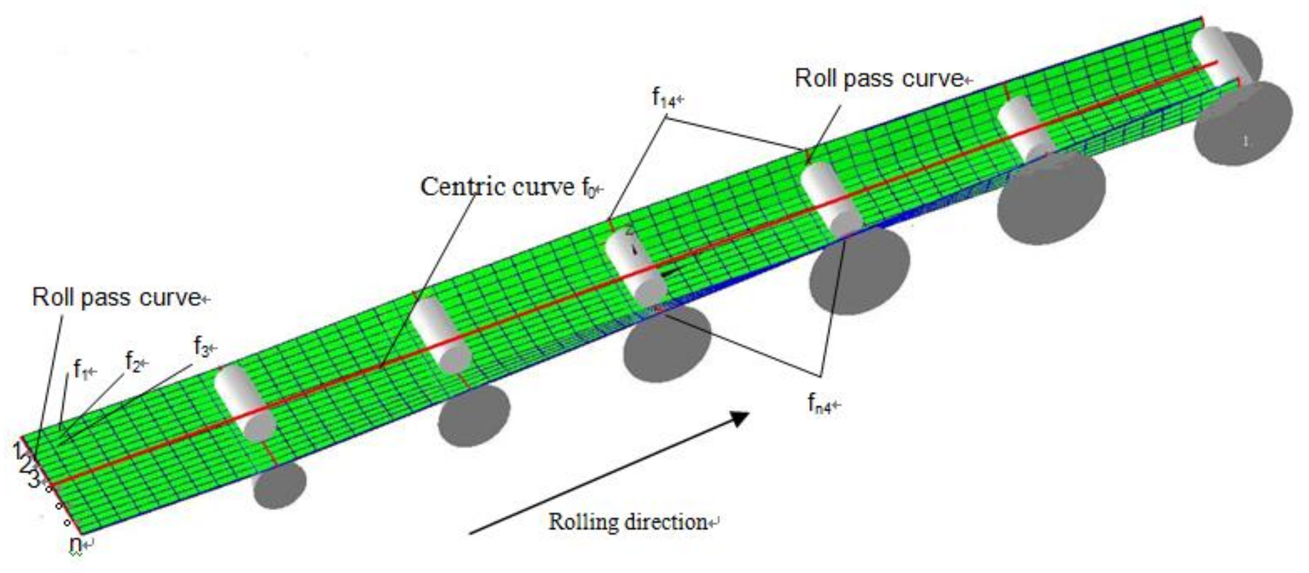
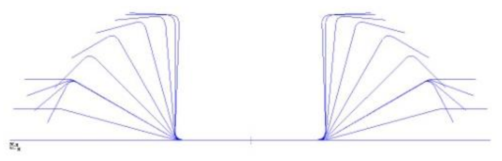
The following is the detailed course to obtain the mean longitudinal strain of the racks. As shown in
Figure 2, if we want to verify the process of forming a channel steel with 7 roll passes, the forming angles are 0°, 15°, 30°,45°, 60°, 75° and 90°. Thus, 7 roll pass curves are formed. These 7 pass curves will divide the plate into 6 parts. Each roll pass curve is divided into
segments and get
points (the curve in
Figure 2).
According to the assumption of straight normal, the points on the normal of the middle surface before deformation are still on the same normal of the surface after deformation, and the distance between the points on the normal is constant. We think the pass curve is coplanar. Apply the spline function with the cumulative chord length parameter to fit the corresponding point on each roll pass curve and form curves .
Calculate the centric point for each roll pass and apply the spline function with a cumulative chord length parameter to fit each coordinate and form the curve function
. Divide
,
,
and
into several parts by the racks, and define the parts as
, where
represents the
i-th point among
points, and
represents
j-th segment in the pass that was divided into 6 segments. Each
is divided into equidistant
points. It is better to take a big value for
, e.g., 30. The
points are connected by straight lines and calculate the length of each line segment to finally obtain the
, total length of the
points. In order to facilitate the description, we choose the part between the first and second rack and, respectively, record it as
and centric line
. Calculate the longitudinal strain of the
curve segment as
. If the longitudinal strain is too small,
could be expressed approximately as
In the same way,
where
represents the
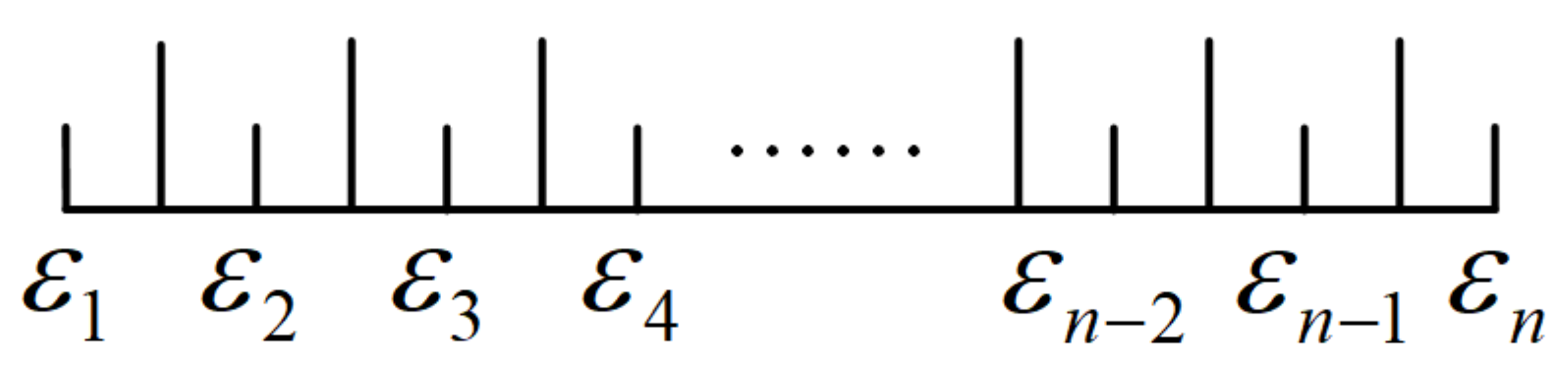
th strain between the first and the second rack. The above is only the approximate longitudinal strain; to make it more accurate, taking it into account that the cold roll forming is a micro-tension course, the tension is approximately equal to 0. Likewise, we study the part between the first and the second rack frame. The initial roll pass segment of the blank is shown in
Figure 3, which is divided into
parts corresponding to
points, which corresponds to the
strains. In order to make the results more accurate, we take the
length of both sides (
and
excluded) with each strain as the center.
As cold roll forming is micro-tension forming, the tensions between racks are ignored. Therefore, section tension
. According to the basic principles of mechanics, we have
Here,
is the segment length after the roll pass is equal divided into
parts,
is the thickness, and
is the modulus of elasticity, so
From Equations (5) and (6), we obtain
is evenly divided into
components, let
Finally, we acquire .
In the same way, we can obtain the strain from the 2nd rack to the 7th rack, and then we obtain the mean longitudinal strain between two adjacent racks. Define the strain as , where is the number of the roll pass points, and is the jth segment of divided by the rack.
Yield strain is the strain value when the material yields. We are usually given material yield stress
since
we get the yield strain
. Each material has a corresponding yield strain, and the yield strain is only an approximate value. However, we can use it as a criterion to determine whether the material has undergone plastic deformation.
According to this theory, the corresponding module, which is used to calculate the mean longitudinal strain, is programmed.
4. An Example of Forming Channel Steel with the Outer Edge
To verify the rationality of this theory, we select channel steel with an outer edge from Shijiazhuang Bearing Equipment Factory.
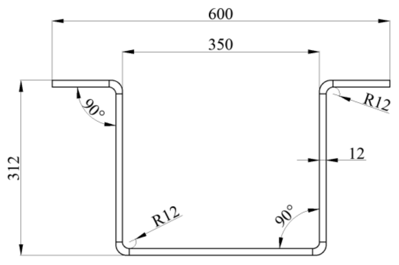
Figure 4 shows the section diagram of the channel steel with an outer edge, and
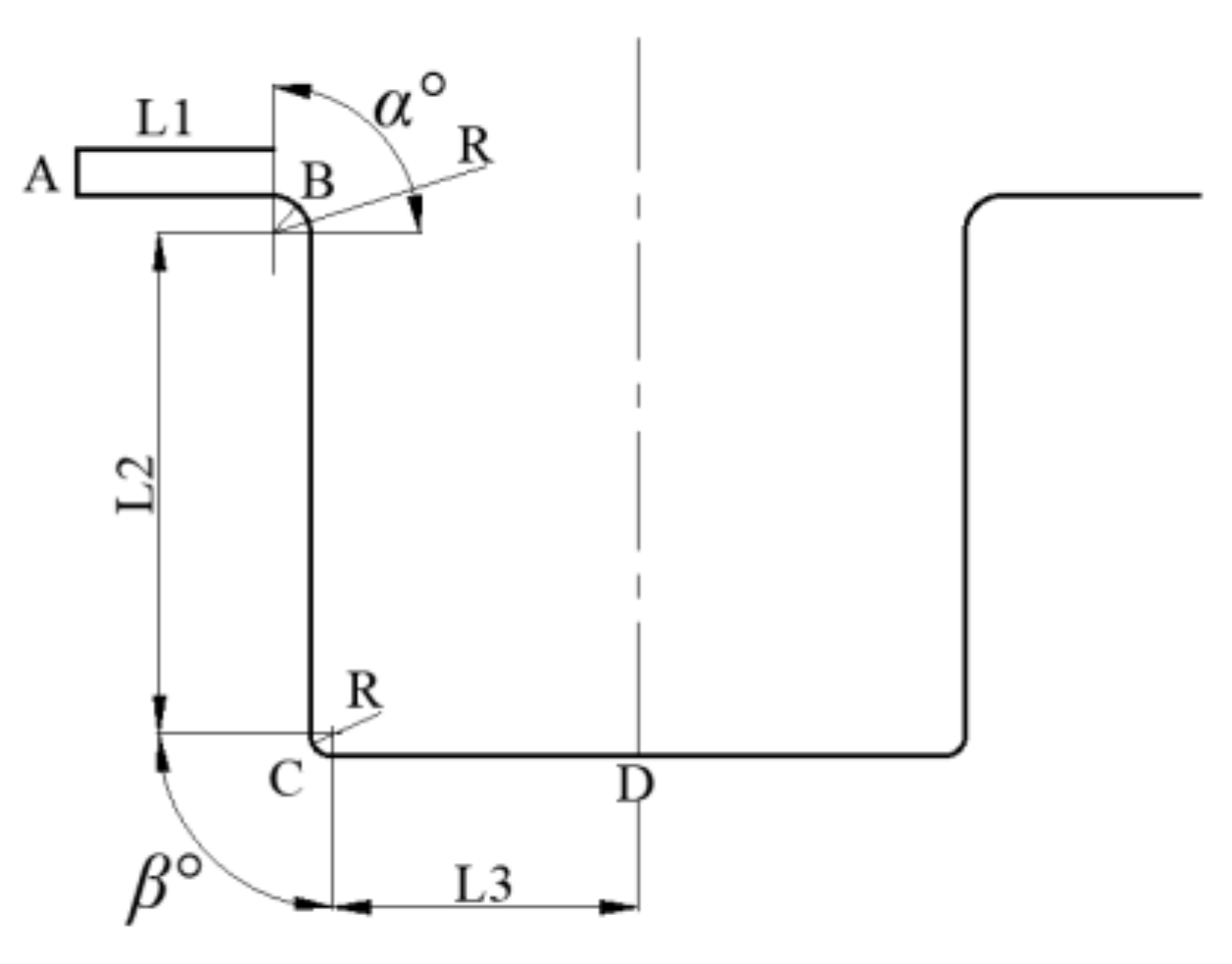
Figure 5 shows the schematic diagram of the blank width calculation of the channel steel with an outer edge. In
Figure 5A–D are invariant points on the strip, and B and C are the midpoints of the arc. R is the fillet radius of B and C. Finally, the blank width is 1160 mm.
The section size of the product is 600 mm × 312 mm × 12 mm. The material is weathering steel Q450. The yield stress of Q450 is 450 MPa, and the elastic modulus is 210,000 MPa. The forming style is Listenfcontinuous roll bend forming. The whole forming unit has nine flat roller machines, two vertical roller machines, three universal roller machines and two straightening machines. Flat rollers are initiative, and vertical rollers are passive. In the computing process, we only consider the nine flat roller machines and three universal roller machines. Two sets of forming parameters are used. The flower diagrams of the two sets of parameters are shown in
Figure 6 and
Figure 7. The distance between adjacent racks is 1200 mm. The first group is proven to produce qualified products effectively, while the second group is not able to produce qualified products. The difference between the two sets of parameters is the bending angle β in the second rack. In the first set, the bending angle is 15 degrees, while in the second set, the bending angle is 30 degrees.
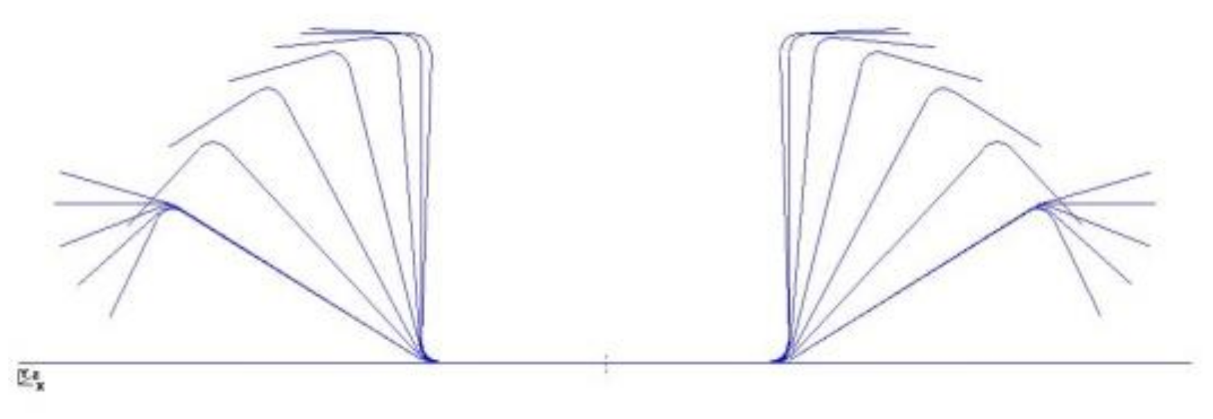
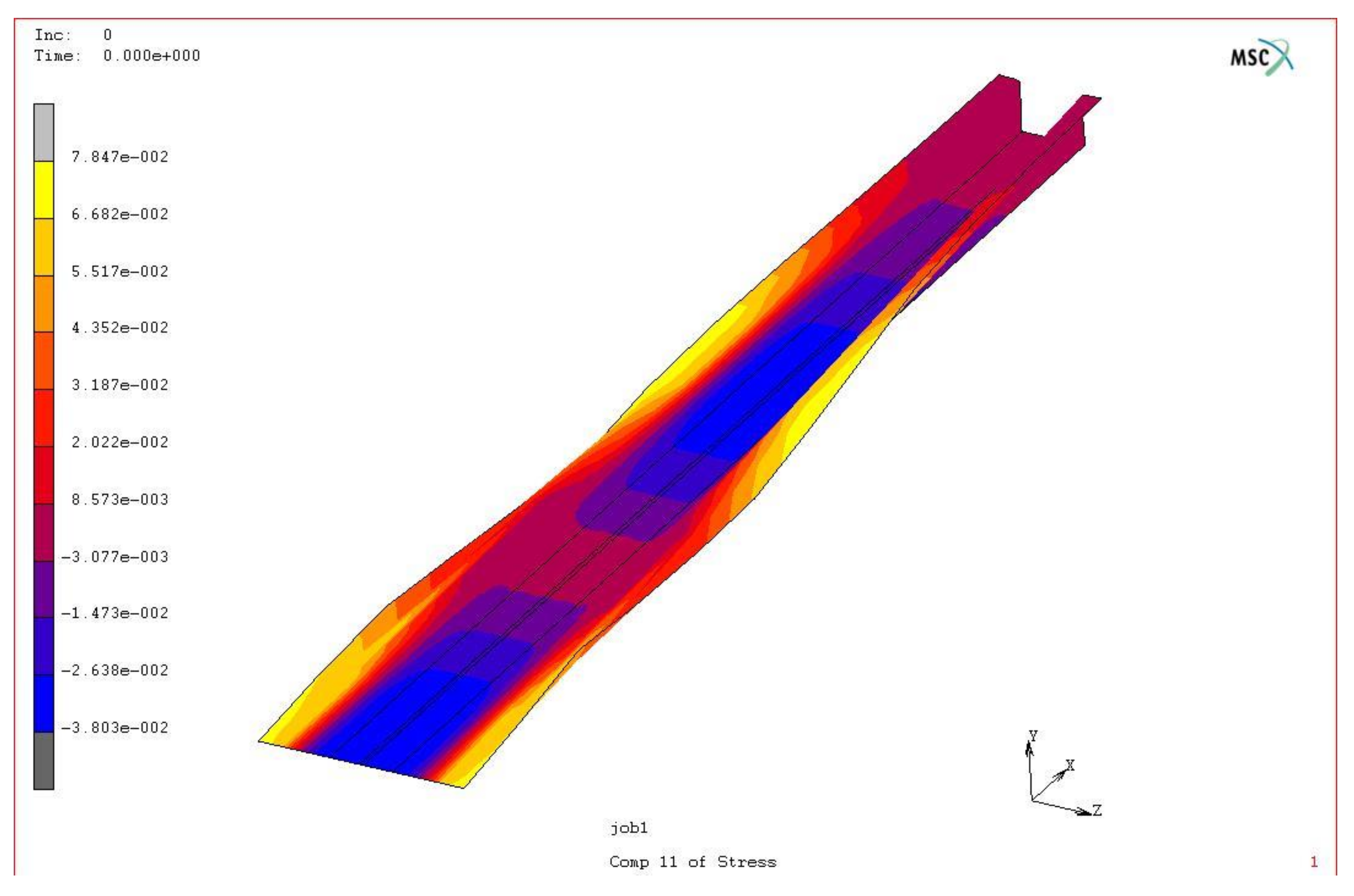
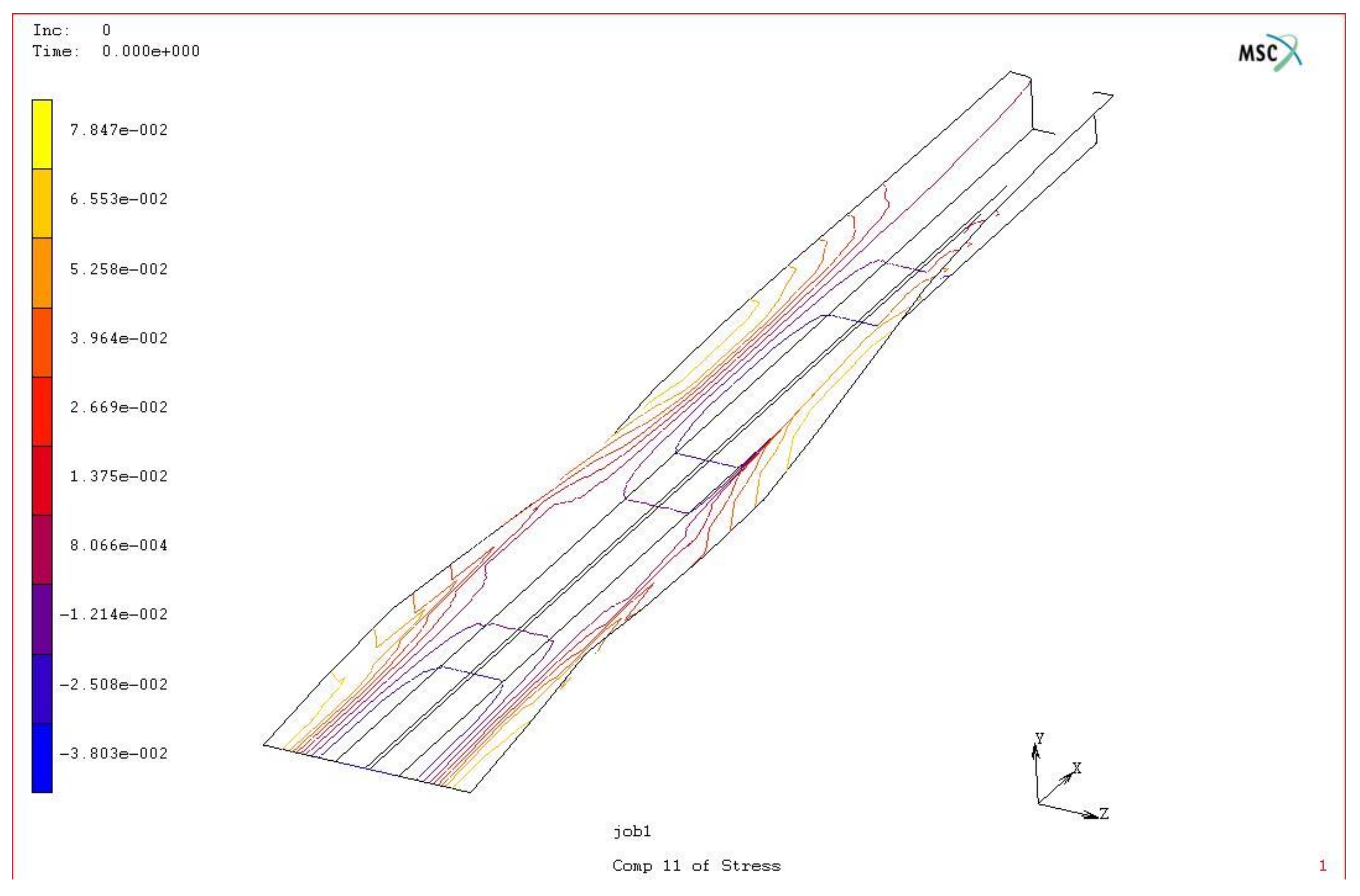
According to the above theory, we calculate the mean longitudinal strain with the first set of parameters. In order to conveniently show the results, the post-processing program of Marc finite element software is applied to show the cloud diagram and contour diagram of the mean longitudinal strain from the 1st to 12th rack.
Figure 8 is the cloud diagram of the mean longitudinal strain from the 1st to 12th rack, and
Figure 9 is the contour diagram. During the forming process, the edge is stretched, the middle part is compressed, and the edge is stretched to a greater extent, as shown in
Figure 8 and
Figure 9.
According to the calculations, the maximum longitudinal tensile strain of the slab is 0.183895%, and the maximum compressive strain is 0.085467%. The material yield strain = 450/210,000 = 0.002143. The longitudinal strain is in the range, so the parameters are reasonable. The biggest mean longitudinal strain of the second group of parameters is 4.00537e-3, which occurred between the first two racks. The value is larger than the yield strain 0.002143, so this group of parameters is not suitable, and the second forming angle has to be changed.
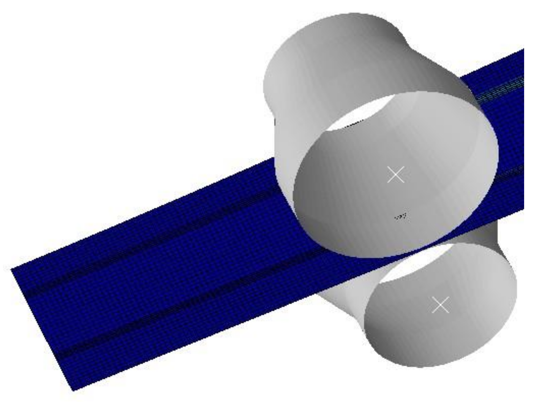
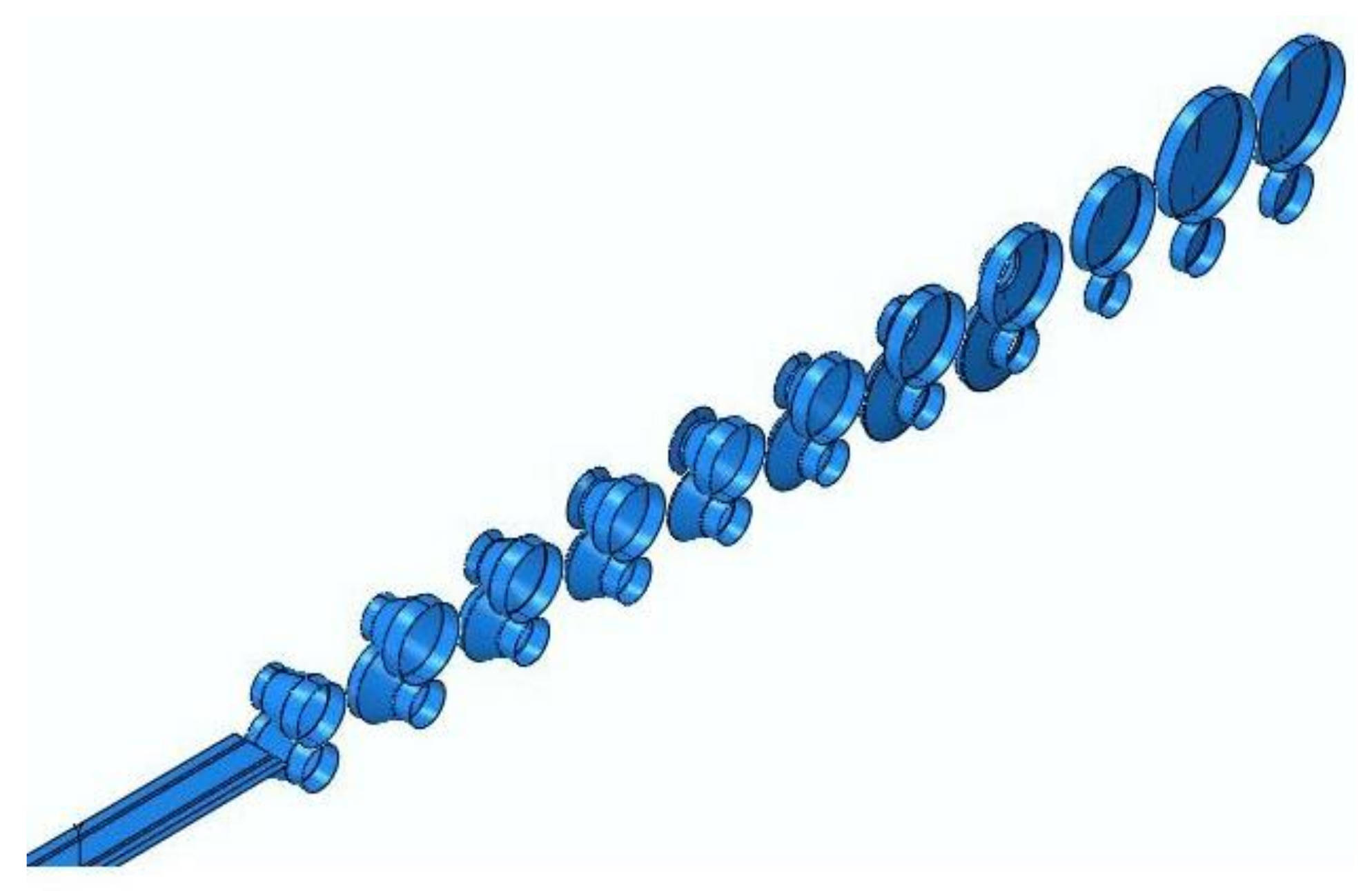
To further prove the correctness of the theory, this paper compares the reasonable analytical results with the results of the non-linear finite element software ABAQUS (6.14). In order to reduce the calculation scale, a half part is selected for finite element modeling as the symmetry of the product. The geometric model in ABAQUS is shown in
Figure 10. The parameters of the finite element geometric model are consistent with those of the analytical method. Because the first frame is a pinch roll, its influence is not considered in the simulation.
In order to reflect the actual rolling process, a series of boundary conditions are set for the simulation process. For each roll, only rotation is allowed. All the lower rolls are active rolls, and all the upper rolls are passive rolls. The linear speed of the lower roller is 200 mm/s. Because the rolls are analytic rigid bodies, only the strip blank needs to be meshed. For cold roll forming, the strip changes greatly at the corner, and the stress is also the largest. Therefore, we subdivide the grid at the corner when meshing, which not only improves the accuracy of calculation but also does not affect the speed. The element type is quadrilateral shell element S4R.
Figure 11 shows the meshing status.
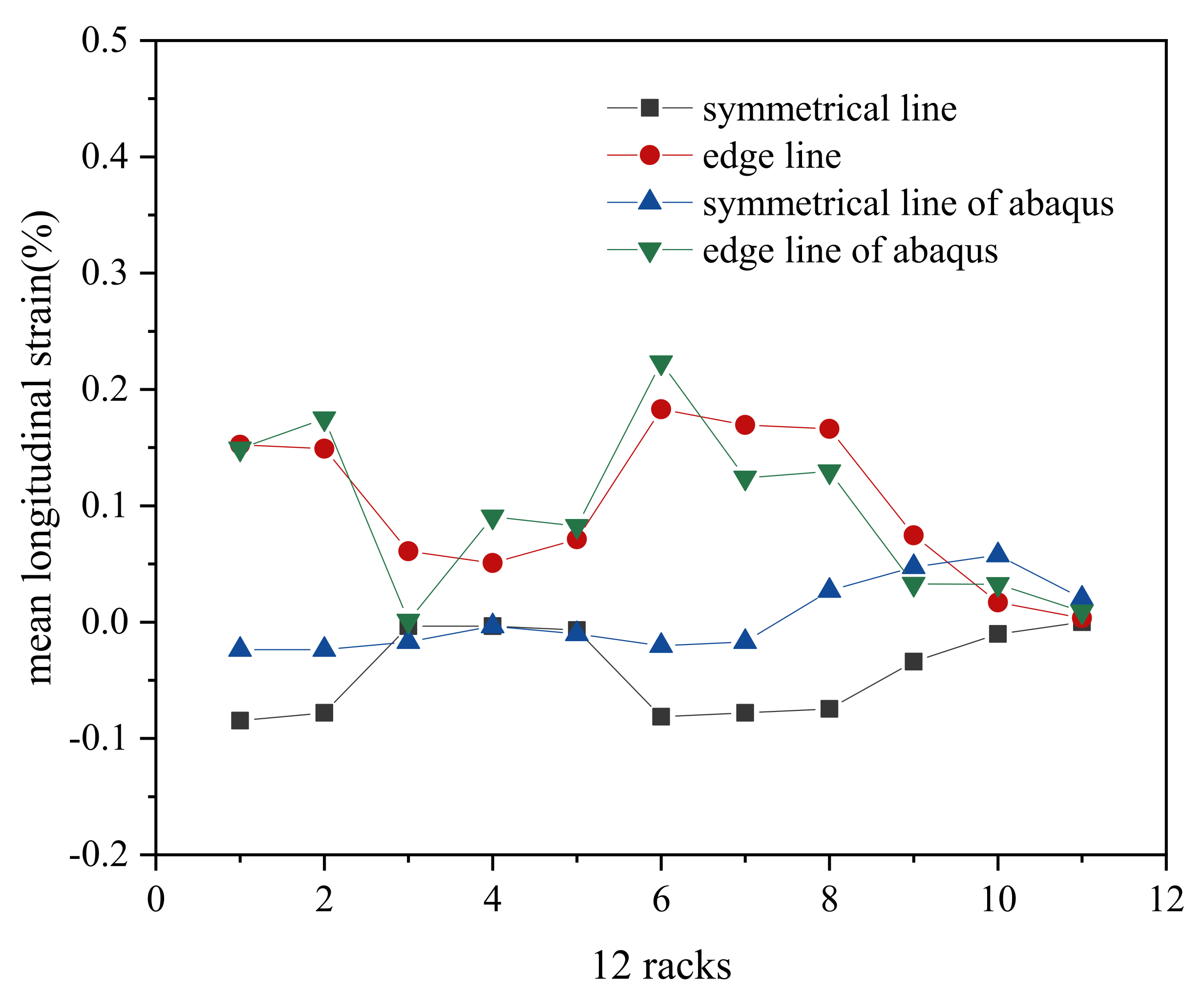
In ABAQUS post-processing, we get the coordinates of each node by analyzing the results after the slab has been formed and calculate the length changes of the edge and symmetrical lines before and after forming between two adjacent racks. The mean longitudinal strain of ABAQUS results can be obtained by these length changes. Compared to the mean longitudinal strain of the edge and symmetrical lines of the ABAQUS results obtained by the above theory, as shown in
Figure 12, the results obtained by the finite element method are more volatile, which is consistent with the actual situation. In the actual rolling process, the material changes are more complex, while the mean longitudinal strain obtained by the analytical method is relatively stable. According to the changes of the curves, the changing trend is accordant. The Pearson correlation coefficient of analytical results and FEM results on the edge line reaches 87%.

