Article

A Triangular Plate Bending Element Based on Discrete Kirchhoff Theory with Simple Explicit Expression

1
School of Civil Engineering, Southeast University, Nanjing 211189, China
2
Institute of Future Underground Space, Southeast University, Nanjing 211189, China
3
Southeast University-Monash University Joint Graduate School, Suzhou 215123, China
*
Author to whom correspondence should be addressed.
Mathematics 2021, 9(11), 1181; https://doi.org/10.3390/math9111181
Submission received: 21 April 2021 / Revised: 18 May 2021 / Accepted: 21 May 2021 / Published: 24 May 2021
(This article belongs to the Special Issue Computational Mechanics in Engineering Mathematics)

Abstract

:
A Simple three-node Discrete Kirchhoff Triangular (SDKT) plate bending element is proposed in this study to overcome some inherent difficulties and provide efficient and dependable solutions in engineering practice for thin plate structure analyses. Different from the popular DKT (Discrete Kirchhoff Theory) triangular element, using the compatible trial function for the transverse displacement along the element sides, the construction of the present SDKT element is based on a specially designed trial function for the transverse displacement over the element, which satisfies interpolation conditions for the transverse displacements and the rotations at the three corner nodes. Numerical investigations of thin plate structures were conducted, using the proposed SDKT element. The results were compared with those by other prevalent plate elements, including the analytical solutions. It was shown that the present element has the simplest explicit expression of the nine-DOF (Degree of Freedom) triangular plate bending elements currently available that can pass the patch test. The numerical examples indicate that the present element has a good convergence rate and possesses high precision.

1. Introduction

Plate and shell structures have played significant roles in mechanical, civil, aerospace and naval engineering for the past several decades. Much effort has been made to study the finite elements of plate and shell structures with high performance and simple formulation [1,2]. Researchers have made great efforts to overcome the difficulty of the C1 continuity requirement for the analysis of thin plate structures. A large number of triangular plate bending elements have been proposed over the past several decades, including the first compatible triangular element HCT [3], the non-conforming and conforming element BCIZ [4,5,6], the very popular discrete Kirchhoff element DKT [7,8,9], the free formulation element T3A [10], hybrid/mixed elements [11,12,13,14], generalized conforming elements [15] and the C1-continuity triangular plate element [16]. Most of these elements possess high accuracy and versatility and have been successfully applied to linear or nonlinear analyses of various plate/shell structures [17,18]. In order to overcome the difficulties of the C1 continuity requirement, the Mindlin–Reissner plate theory was proposed for thin and thick plates [19,20], which only required C0 continuity for the displacement functions of the element. However, due to the so-called shear locking phenomenon, these Mindlin–Reissner plate elements usually led to poor results for the analysis of thin plates [21]. Many efforts have been made to eliminate the shear locking phenomenon, such as the assumed natural stain approach, the reduced integration approach, mixed/hybrid stress elements and assumed stress elements. The reduced integration approach was developed by Zienkiewicz et al. [22] and Pugh et al. [23]. The selective integration method was also employed for plate and shell analyses [24,25]. Bathe and Dvorkin [26] proposed the MITC family, and Nguyen et al. [27] developed the MISC element. Other popular plate elements also include the assumed stress/strain elements by Lee and Pian [28], Katili [29] and Brasile [30]; the RDKTM by Chen and Cheung [17]; and the DST family by Batoz and Katili [31], and Batoz and Lardeur [32]. Most of these elements for thick plates can avoid the shear locking phenomenon, but they usually need very complicated formulations and, thus, bring a lot of difficulties and computational cost for the programming of the elements.
Among all of the abovementioned triangular plate bending elements, the most prevalent elements are the BCIZ and DKT. The BCIZ element developed by Bazeley et al. [4] is the simplest of the above-mentioned elements. However, it is well known that the BCIZ fails to pass the patch test due to its incompatibility. Compatible BCIZ elements were developed by Razzaque [5] and Cheung and Chen [6], but they are rarely used due to the complex formulation. The DKT element is one of the most reliable and efficient plate-bending elements, but the complicated implementation and the complex explicit expression [8] hinder the widespread use of the DKT element, to a certain extent.
In this paper, a Simple, three-node, Discrete Kirchhoff Triangular (SDKT) plate bending element is proposed to overcome the abovementioned difficulties of the existing plate elements and provide efficient and dependable solutions for the analyses with plate elements. It will be shown in the following sections that the SDKT is the simplest of the nine-DOF triangular plate bending elements currently available that can pass the patch test, has a good convergence rate and possesses high precision.

2. Displacement Function of the SDKT Element

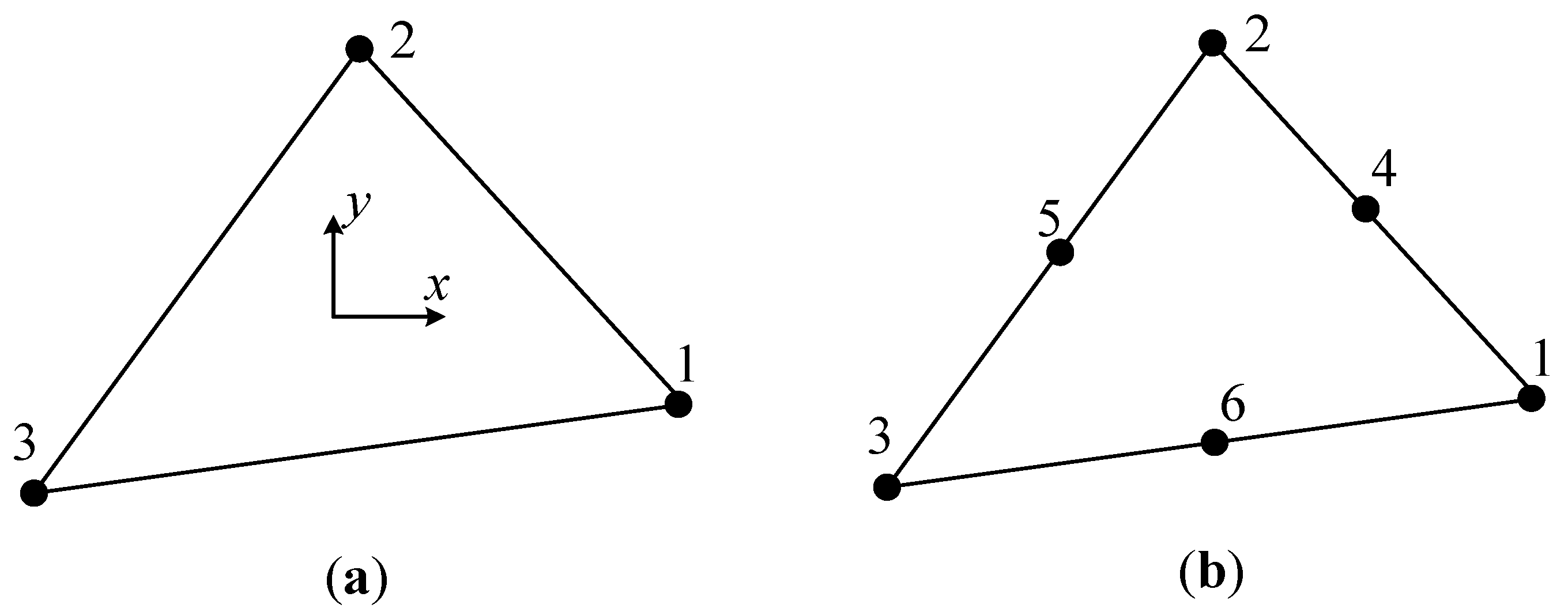
2.1. Transverse Displacement Function of the Element

In order to start the formulation of the SDKT element, first we consider the triangular element as shown in Figure 1. In Figure 1a, the triangle with only three corner nodes is used for interpolation of the transverse displacement over the element; in Figure 1b, the triangle has six nodes, including three corner nodes and three mid-side nodes, which are used for interpolation of the rotation over the element.
The trial functions for transverse displacement w, in each element, are assumed as follows:
w = i = 1 3 L i [ d 1 i + 1 2 ( y y i ) d 2 i 1 2 ( x x i ) d 3 i ]
where Li are the area coordinates of the three-node triangular element in the common finite element analysis, and d1i, d2i and d3i are the generalized DOFs of the nodes i, xi = (xi, yi) which are the coordinates of the nodes i. Li can be expressed as follows:
L i = 1 2 A ( a i + b i x + c i y )
a i = x j y m x m y j ,   b i = y j y m ,   c i = x j + x m
where A is the area of the triangular element, and i = 1, 2, 3; j = 2, 3, 1; m = 3, 1, 2.
By using Equation (2), Equation (1) can be rewritten as follows:
w = 1 2 A i = 1 3 { ( a i + b i x + c i y ) [ d 1 i + 1 2 ( y y i ) d 2 i 1 2 ( x x i ) d 3 i ] } = β 1 + β 2 x + β 3 y + β 4 x y + β 5 x 2 + β 6 y 2
where
β 1 = 1 2 A i = 1 3 ( a i d 1 i + 1 2 a i d 3 i x i 1 2 a i d 2 i y i ) β 2 = 1 4 A i = 1 3 ( a i d 3 i + b i d 3 i x i b i d 2 i y i + 2 b i d 1 i ) β 3 = 1 4 A i = 1 3 ( a i d 2 i + c i d 3 i x i c i d 2 i y i + 2 c i d 1 i ) β 4 = 1 4 A i = 1 3 ( b i d 2 i c i d 3 i ) β 5 = 1 4 A i = 1 3 ( b i d 3 i ) β 6 = 1 4 A i = 1 3 ( c i d 2 i )
Here, we select the following:
d 1 i = w i = w | x = x i , d 2 i = θ x i = w y | x = x i , d 3 i = θ y i = w x | x = x i
Substituting Equation (4) into Equation (6), we have the following:
d 1 i = β 1 + β 2 x i + β 3 y i + β 4 x i y i + β 5 x i 2 + β 6 y i 2 d 2 i = β 3 + β 4 x i + 2 β 6 y i d 3 i = β 2 β 4 y i 2 β 5 x i
Substituting Equation (7) into Equation (1) and using i = 1 3 L i = 1 , i = 1 3 L i x i = x and i = 1 3 L i y i = y , we have the following:
w = i = 1 3 L i [ β 1 + β 2 x i + β 3 y i + β 4 x i y i + β 5 x i 2 + β 6 y i 2 + 1 2 ( y y i ) ( β 3 + β 4 x i + 2 β 6 y i ) + 1 2 ( x x i ) ( β 2 + β 4 y i + 2 β 5 x i ) ] β 1 + β 2 x + β 3 y + β 4 x y + β 5 x 2 + β 6 y 2
From Equations (1), (4), (6) and (8), we can conclude that the following transverse displacements,
w = i = 1 3 L i [ w i + 1 2 ( y y i ) θ x i 1 2 ( x x i ) θ y i ]
satisfy the condition,
w i = w | x = x i , θ x i = w y | x = x i , θ y i = w x | x = x i
at the three corner nodes.

2.2. The Kirchhoff Hypothesis

By using Equation (9), the displacements of the SDKT element are defined as follows:
w = i = 1 3 ( φ i w i + φ x i θ x i + φ y i θ y i ) θ x = j = 1 6 N j θ x j θ y = j = 1 6 N j θ y j
where Nj are the shape functions of the six-node triangular element in Figure 1b.
φ i = L i ,   φ x i = 1 2 ( y y i ) L i ,   φ y i = 1 2 ( x x i ) L i
N j = ( 2 L j 1 ) L j ( j = 1 , 2 , 3 ) N 4 = 4 L 1 L 2 , N 5 = 4 L 2 L 3 , N 6 = 4 L 3 L 1
The Kirchhoff hypothesis of the present element is imposed at the following:
(a)
The corner nodes in Figure 1a,
θ x i = w y | x = x i , θ y i = w x | x = x i a t   n o d e s   i   ( i = 1 , 2 , 3 )
(b)
The mid-side nodes in Figure 1b,
θ x k = w y | x = x k , θ y k = w x | x = x k a t   n o d e s   k   ( k = 4 , 5 , 6 )
The Kirchhoff condition in Equation (14) at the corner nodes is naturally satisfied in Equation (11) of the transverse displacement function w.
Substituting Equation (11) into Equation (15), we have the following:
θ x k = i = 1 3 ( φ i , y w i + φ x i , y k θ x i + φ y i , y k θ y i ) θ y k = i = 1 3 ( φ i , x w i + φ x i , x k θ x i + φ y i , x k θ y i ) ( k = 4 , 5 , 6 )
where
φ i , y = L i , y ,   φ x i , y k = 1 2 [ L i ( x k ) + ( y k y i ) L i , y ]   ,   φ y i , y k = 1 2 ( x k x i ) L i , y φ i , x = L i , x ,   φ x i , x k = 1 2 ( y k y i ) L i , x ,   φ y i , x k = 1 2 [ L i ( x k ) + ( x k x i ) L i , x ]

2.3. Displacement Function of the Element

Substituting Equation (16) into Equation (11), the surplus parameters θxk and θyk at the mid-side nodes k (k = 4, 5, 6) in Figure 1b can be finally eliminated:
θ x = i = 1 3 N i θ x i + k = 4 6 N k θ x k = i = 1 3 ( R i w i + R x i θ x i + R y i θ y i ) θ y = i = 1 3 N i θ y i + k = 4 6 N k θ y k = i = 1 3 ( Q i w i + Q x i θ x i + Q y i θ y i )
where
R i = ( k = 4 6 N k ) φ i , y ,   R x i = N i + k = 4 6 ( N k φ x i , y k ) ,   R y i = k = 4 6 ( N k φ y i , y k ) Q i = ( k = 4 6 N k ) φ i , x ,   Q x i = k = 4 6 ( N k φ x i , x k ) ,   Q y i = N i k = 4 6 ( N k φ y i , x k )
Finally, the displacement trial function of the SDKT element can be expressed as follows:
{ w θ x θ y } = N ˜ a e = [ N ˜ 1   N ˜ 2   N ˜ 3 ] { a 1 a 2 a 3 }
where
N ˜ i = [ φ i φ x i φ y i R i R x i R y i Q i Q x i Q y i ] , a i = { w i θ x i θ y i } ( i = 1 , 2 , 3 )
where ( ϕ i , ϕ x i , ϕ y i ) are defined in Equation (12), and ( R i , R x i , R y i ) and ( Q i , Q x i , Q y i ) are defined in Equation (19). We can see that the explicit expression and implementation of the SDKT element in Equation (20) are much simpler than the existing nine-DOF triangular plate elements, passing the patch test.

3. Stiffness Matrix of the SDKT Element

By using the displacement function in Equation (20), the stiffness matrix of the SDKT element for thin plates based on Kirchhoff theory can be written as follows:
K e = Ω e B T D b B d x d y
where
B = [ B 1 B 2 B 3 ]
B i = [ Q i , x Q x i , x Q y i , x R i , y R x i , y R y i , y Q i , y R i , x Q x i , y R x i , x Q y i , y R y i , x ]   ( i = 1 , 2 , 3 )
D b = D [ 1 ν 0 ν 1 0 0 0 ( 1 ν ) / 2 ]
where D = E h 3 12 ( 1 υ 2 ) . E is the elastic modulus, ν is the Poisson’s ratio and h represents the thickness of the plate.

4. Comparison with the DKT Element

4.1. The Brief Formulation of DKT Element

The derivation and formulation of DKT element can be found in the paper by Batoz, Bathe and Ho [8]. They are briefly listed here to compare with the above proposed SDKT element.
As shown in Figure 2, the derivatives of the transverse displacement w of a triangular plate element around the two independent axes are defined as follows:
θ x = w x ,   θ y = w y
The Kirchhoff hypotheses are presented in the following discrete way:
(a)
At the corner nodes i,
θ x i = w x | x = x i , θ y i = w y | x = x i   ( i = 1 , 2 , 3 )
(b)
At the mid-side nodes k,
θ n k = 1 2 ( θ n i + θ n j ) θ s k = w s | x = x k = 1.5 l k ( w j w i ) 1 4 ( θ s i + θ s j ) ( k = 4 , 5 , 6 )
where xi = (xi, yi) are the coordinates of the nodes i; lk represents the length of the element side ij; s and n indicate the tangent and normal direction of the element side ij, respectively; and i = 1, 2, 3 and j = 2, 3, 1 when k = 4, 5, 6.
Along the element side ij,
{ θ s k θ n k } = [ cos   α k sin   α k sin   α k cos   α k ] { θ x k θ y k } ( k = 4 , 5 , 6 )
The rotations θx and θy are defined as follows:
θ x = i = 1 6 N i θ x i θ y = i = 1 6 N i θ y i
where
N i = ( 2 L i 1 ) L i ( i = 1 , 2 , 3 ) N 4 = 4 L 1 L 2 , N 5 = 4 L 2 L 3 , N 6 = 4 L 3 L 1
The expressions of Li are the same as those in Equations (2) and (3).
By using Equations (27) to (30), the displacements of the DKT element are obtained as follows:
θ x = i = 1 3 ( D i w i + D x i θ x i + D y i θ y i ) θ y = i = 1 3 ( H i w i + H x i θ x i + H y i θ y i )
where
D 1 = 1.5 ( m 6 N 6 l 6 m 4 N 4 l 4 ) , D 2 = 1.5 ( m 4 N 4 l 4 m 5 N 5 l 5 ) , D 3 = 1.5 ( m 5 N 5 l 5 m 6 N 6 l 6 ) , D x 1 = N 1 + N 4 ( 0.5 n 4 2 0.25 m 4 2 ) + N 6 ( 0.5 n 6 2 0.25 m 6 2 ) , D x 2 = N 2 + N 4 ( 0.5 n 4 2 0.25 m 4 2 ) + N 5 ( 0.5 n 5 2 0.25 m 5 2 ) , D x 3 = N 3 + N 5 ( 0.5 n 5 2 0.25 m 5 2 ) + N 6 ( 0.5 n 6 2 0.25 m 6 2 ) , D y 1 = 0.75 ( m 4 n 4 N 4 + m 6 n 6 N 6 ) , D y 2 = 0.75 ( m 4 n 4 N 4 + m 5 n 5 N 5 ) , D y 3 = 0.75 ( m 5 n 5 N 5 + m 6 n 6 N 6 )
H 1 = 1.5 ( n 6 N 6 l 6 n 4 N 4 l 4 ) , H 2 = 1.5 ( n 4 N 4 l 4 n 5 N 5 l 5 ) , H 3 = 1.5 ( n 5 N 5 l 5 n 6 N 6 l 6 ) , H x 1 = 0.75 ( m 4 n 4 N 4 + m 6 n 6 N 6 ) , H x 2 = 0.75 ( m 4 n 4 N 4 + m 5 n 5 N 5 ) , H x 3 = 0.75 ( m 5 n 5 N 5 + m 6 n 6 N 6 ) , H y 1 = N 1 + N 4 ( 0.5 m 4 2 0.25 n 4 2 ) + N 6 ( 0.5 m 6 2 0.25 n 6 2 ) , H y 2 = N 2 + N 4 ( 0.5 m 4 2 0.25 n 4 2 ) + N 5 ( 0.5 m 5 2 0.25 n 5 2 ) , H y 3 = N 3 + N 5 ( 0.5 m 5 2 0.25 n 5 2 ) + N 6 ( 0.5 m 6 2 0.25 n 6 2 )
and
m k = cos   α k , n k = sin   α k ( k = 4 , 5 , 6 )
The subsequent procedure to obtain the stiffness matrix of DKT element is similar with that of the SDKT element, as shown in Section 3.

4.2. Some Comments on SDKT Element

In Section 4.1, the formulations of the displacement function of the popular DKT element are listed very briefly. As compared with those of the SDKT element in Section 2.3, we can see that the formulations for the proposed SDKT element are much simpler. Moreover, it is very easy and convenient to incorporate the SDKT element in a finite element program. Numerical examples in the next section will also demonstrate the fine performances of this element.

5. Numerical Examples
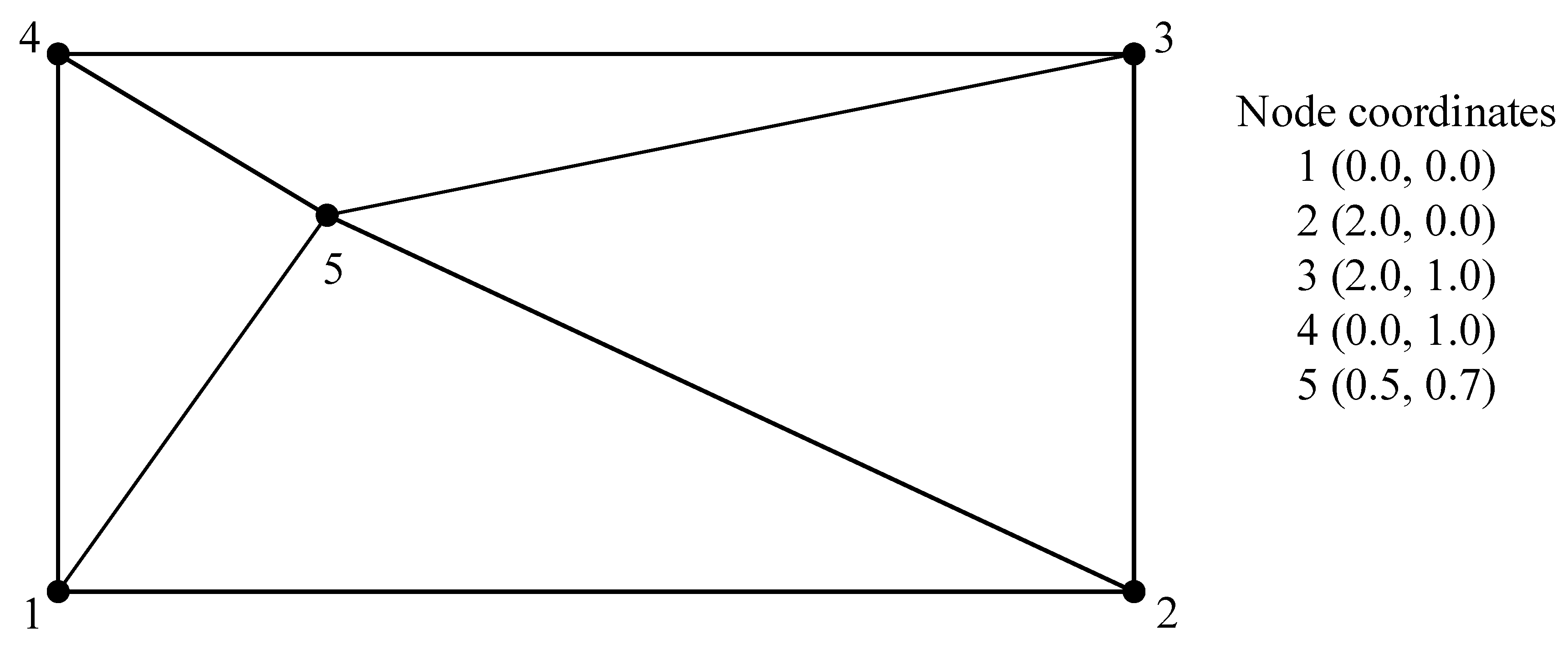
5.1. Patch Test

For the proposed SDKT element, its stiffness matrix should pass the patch test to produce dependable results. Here, the patch test suggested by Katili [29], and Batoz and Katili [31] is employed to check the performance of the current SDKT element.
A plate with an arbitrary mesh is shown in Figure 3. The thickness of the plate is h = 0.01, and the material properties of the plate are E = 107 and ν = 0.3. The patch test is performed by enforcing the following boundary conditions:
w = x 2 + x y + y 2 , θ x = x + 2 y , θ y = ( 2 x + y )
The numerical results are listed in Table 1, which illustrate that the present SDKT element passed the patch test, while the BCIZ element failed to pass the patch test.

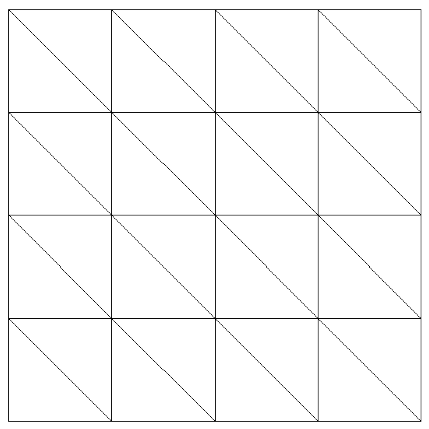
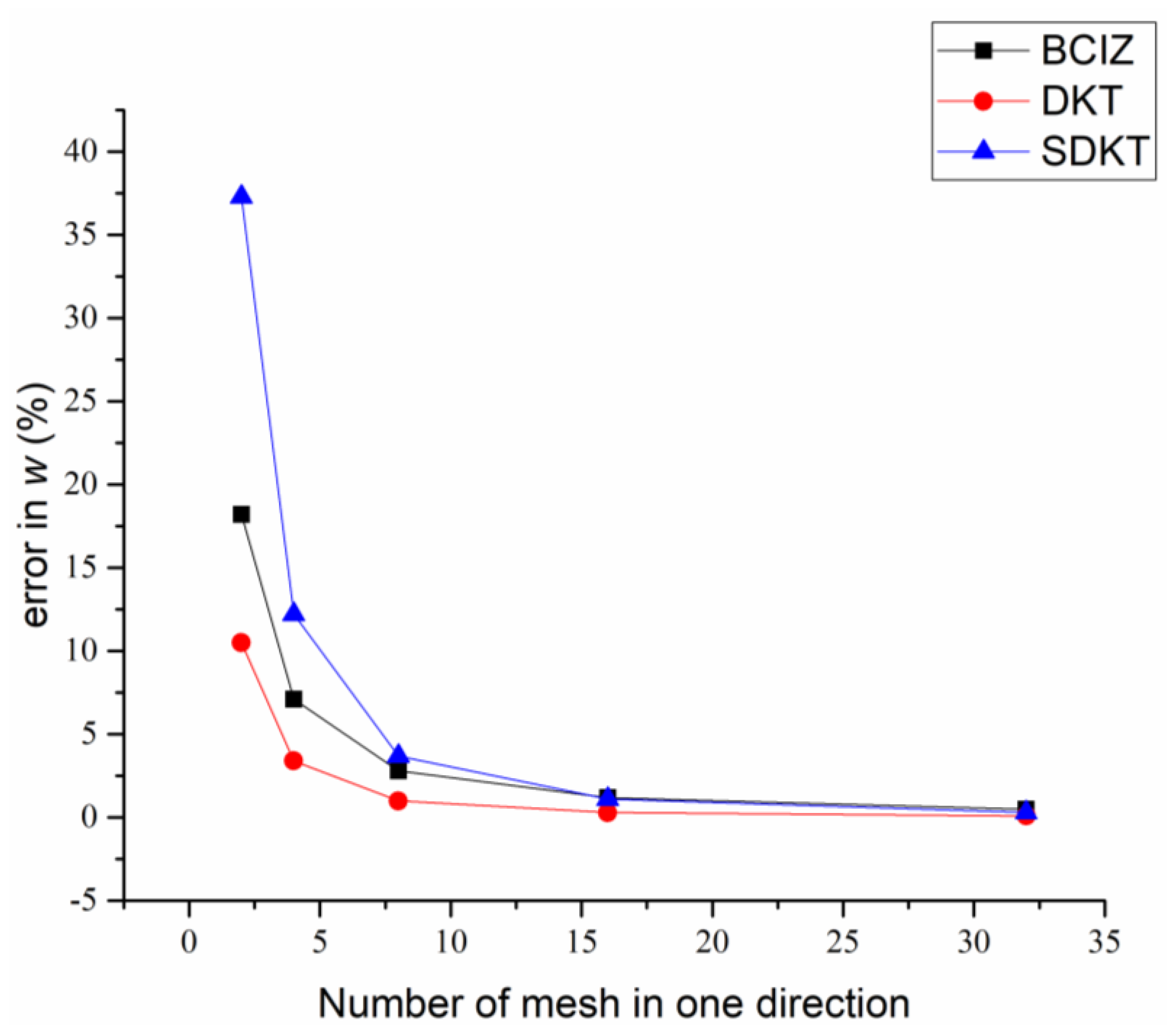
5.2. Square Plate under Uniform Load

In this example, a simply supported or clamped square plate subjected to uniform surface load q is considered. The length of the side of the square plate is l, and the thickness of the plate is h. The assumed material properties are E = 107 and ν = 0.3. Only one quarter of the plate is modeled due to the double symmetry of the whole problem, which is shown in Figure 4. Figure 5 illustrates the central deflection of a simply supported and clamped square plate under uniform load when the mesh is 4 × 4 for one quarter of the plate, using the SDKT element.
Table 2 and Table 3 list the results given by the BCIZ, DKT and SDKT, which are further illustrated in Figure 6 and Figure 7 to show the convergence of these elements. It can be seen that when a very coarse mesh is used, i.e., 2 × 2 or 4 × 4, the residual error given by the SDKT is higher than other elements. However, when a dense mesh is used, such as 16 × 16 or 32 × 32, which is of acceptable computational cost in practice, the SDKT has almost the same accuracy as compared with the other elements. In substantial application, the SDKT is more favorable than the other two types of elements since it has a much simpler explicit expression and can be more easily incorporated in a finite element program.

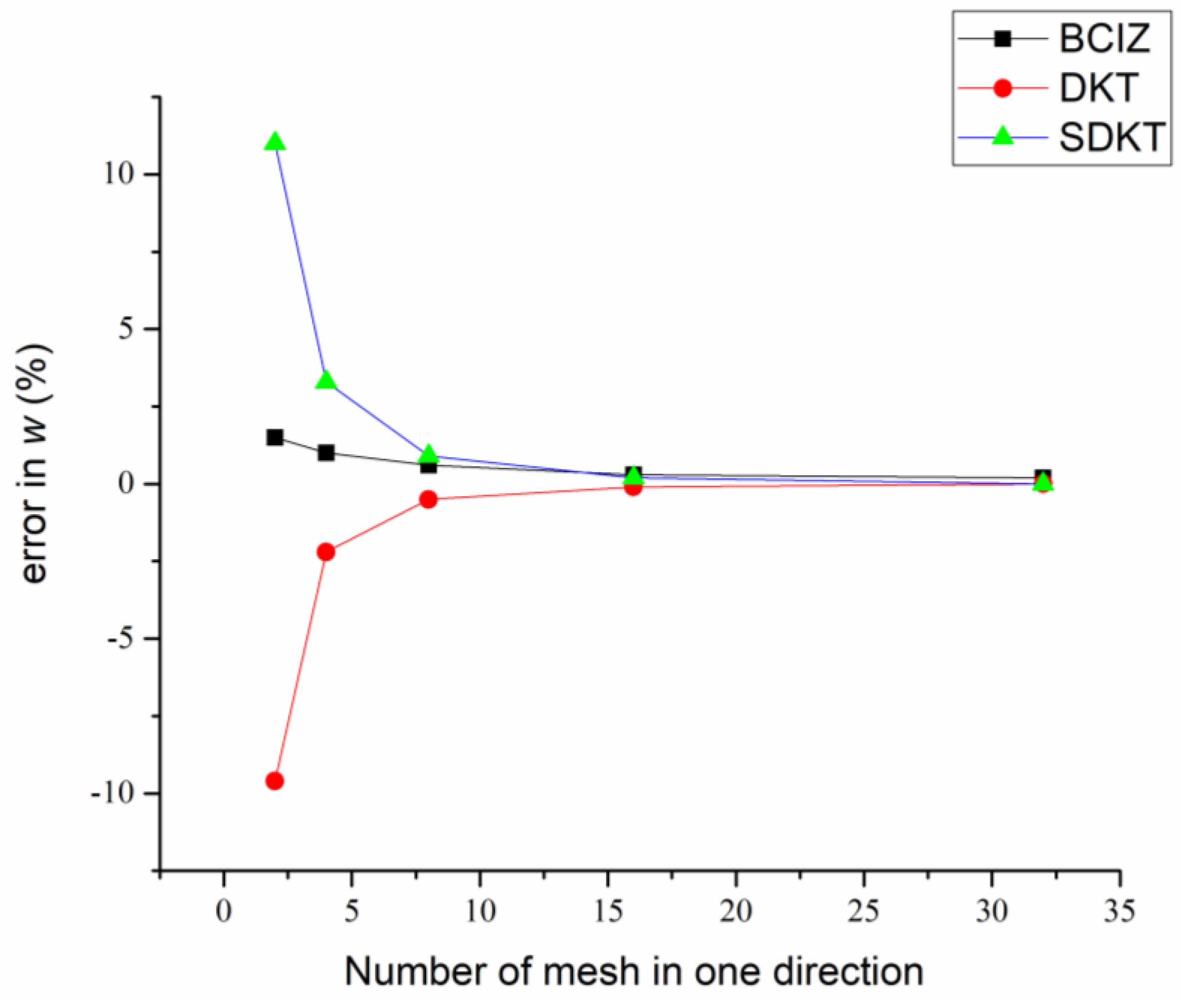
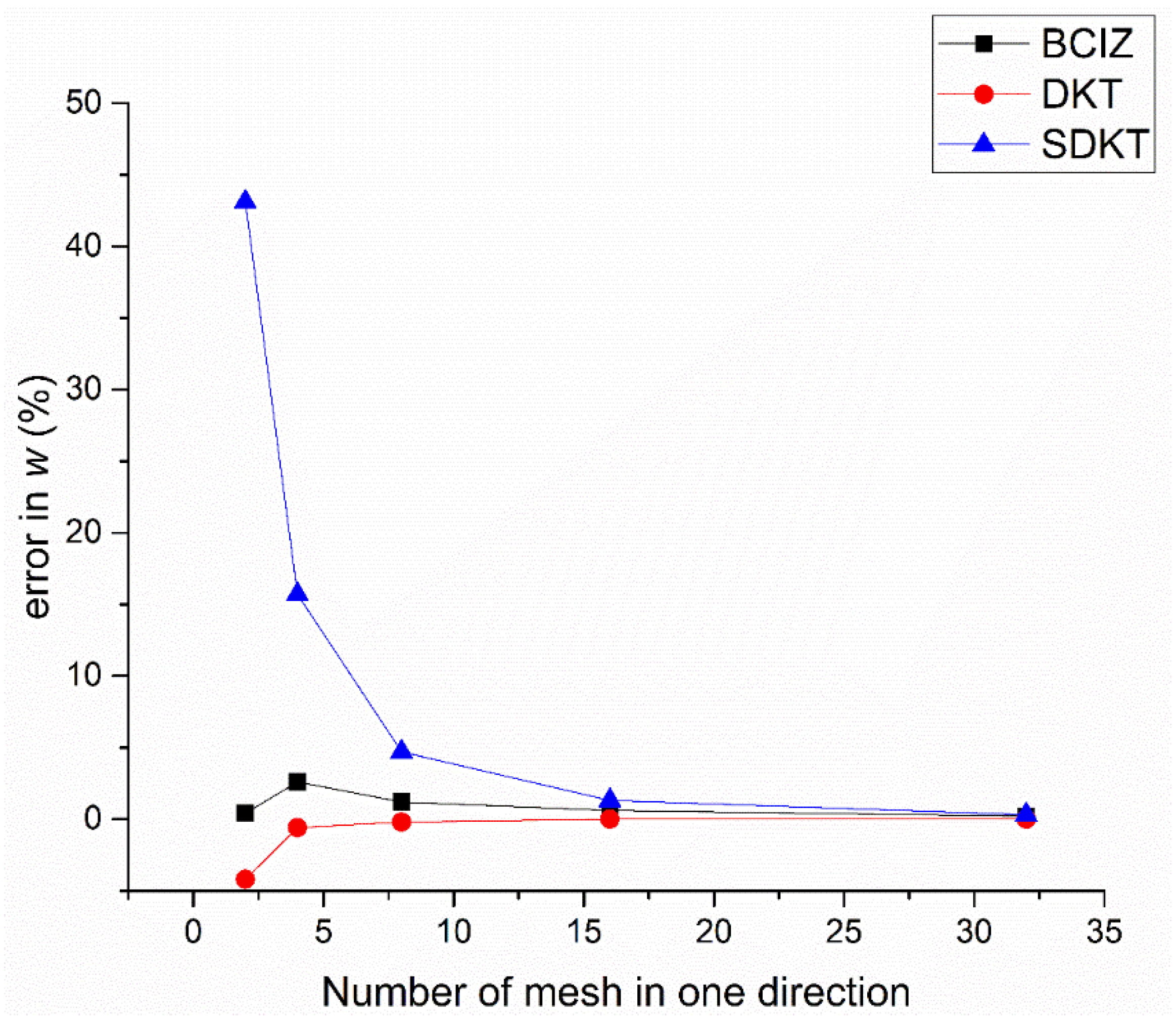
5.3. Square Plate under Point Load

In this example, the same plate is used for the analysis, while the plate is loaded by a point load p at its center. The length of the side of the square plate is l, and the thickness of the plate is h. The assumed material properties of the plate are E = 107 and ν = 0.3. Only one quarter of the plate is modeled in the same way as shown in Figure 4 due to its double symmetry. Figure 8 shows the central deflection of a simply supported and clamped square plate under center point load when the mesh is 16 × 16 for one quarter of the plate, using the SDKT element.
Table 4 and Table 5 list the results given by the BCIZ, DKT and SDKT, which are further illustrated by Figure 9 and Figure 10 to show the convergence of these elements. It can be seen that when a very coarse mesh is used, the residual error given by the SDKT is higher than other elements. However, when a dense mesh is used, which is of acceptable computational cost in practice, the SDKT has almost the same accuracy as compared with the other elements. All these results indicate the good accuracy and convergence rate of the present SDKT.

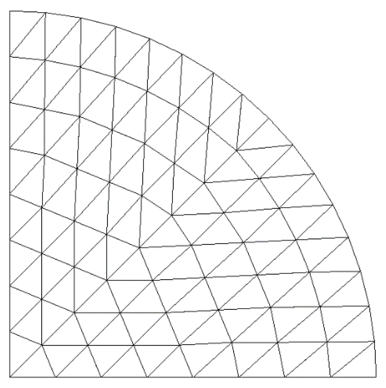
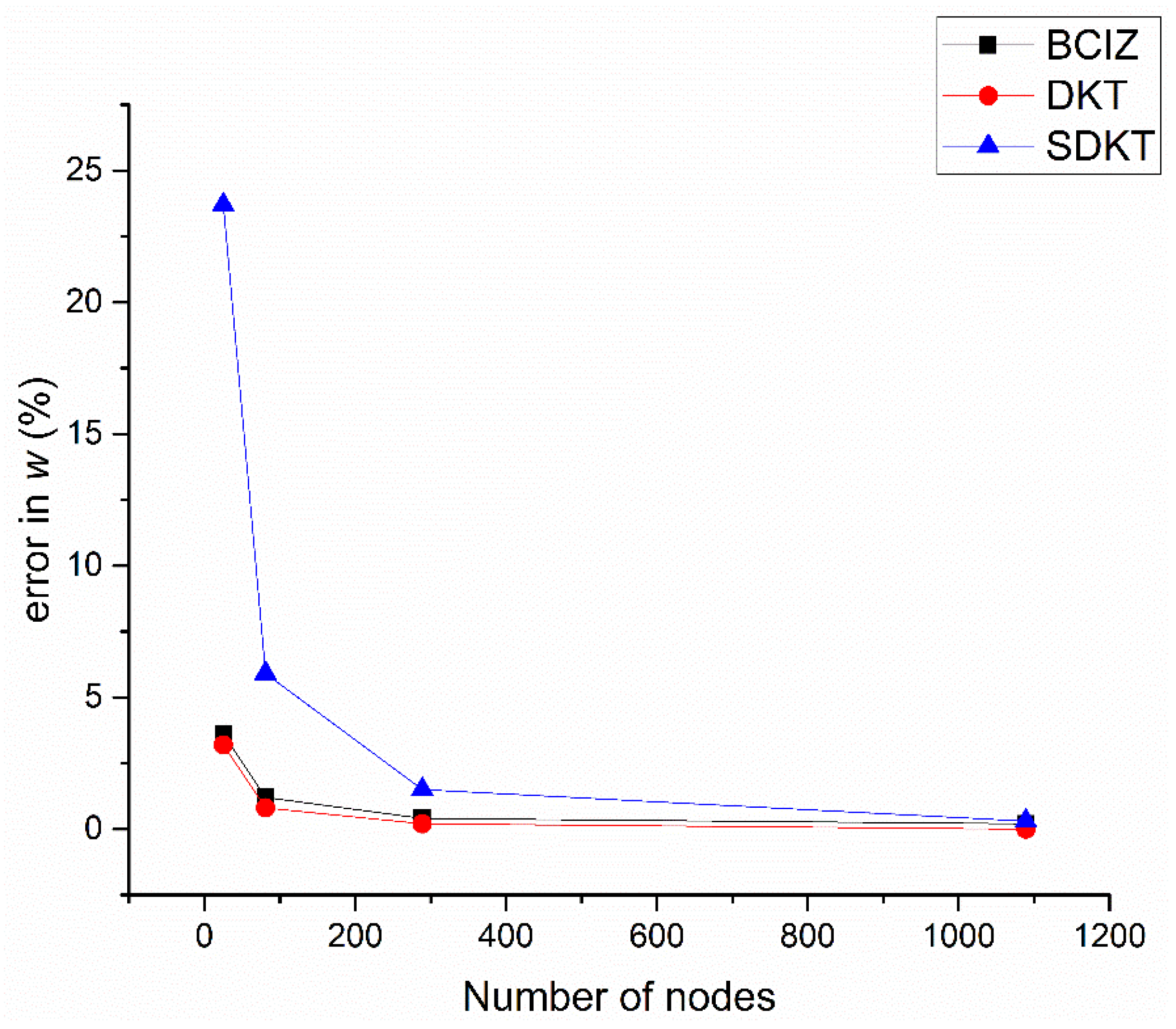
5.4. Circular Plate under Uniform Load

In this example, a clamped circular plate subjected to uniformly distributed load q is studied. The thickness of the plate is h = 1, and radius of the plate is r = 100. The material properties of the plate are E = 107 and ν = 0.3. Only one quarter of the plate is discretized as shown in Figure 11 due to the double symmetry property. Overall, dependable results are obtained for this problem with the SDKT element, as listed in Table 6 and shown in Figure 12.

6. Conclusions

In this paper, a new SDKT element is proposed for the analysis of thin plate structures, based on a specially designed trial function for the transverse displacement and the Discrete Kirchhoff Theory. The present SDKT element is a nine-DOF triangular plate bending element with very simple explicit expression, which can be easily incorporated in a finite element program. It is believed to be the simplest nine-DOF triangular plate bending element currently available that can pass the patch test. The formulations of the present SDKT element are compared with those of the DKT element to show its simplicity in formulation. In the numerical examples, the results by the SDKT element are also compared with the analytical solutions and results by other popular plate elements, demonstrating the overall good performance of the SDKT element.
The SDKT element proposed in this paper is a nine-DOF triangular plate bending element, which does not take the influence of the transverse shear deformation into account, so the present element can only be applied to thin plate structures, currently. To consider the influence of the transverse shear deformation, the displacement function of the plate element should be further studied and improved; shear-deformable plate elements are needed for thick to very thin plates, which will be our research topic in the future.

Author Contributions

Conceptualization, L.T.; methodology, L.T.; software, Z.C.; data curation, Z.C.; writing—original draft preparation, L.T.; writing—review and editing, Z.C.; project administration, L.T.; funding acquisition, L.T. Both authors have read and agreed to the published version of the manuscript.

Funding

This research was funded by National Natural Science Foundation of China, grant number 51808114; Natural Science Foundation of Jiangsu Province, grant number BK20170670.

Conflicts of Interest

The authors declare no conflict of interest.

References

  1. Iura, M.; Atluri, S.N. Advances in finite rotations in structural mechanics. CMES Comp. Model. Eng. 2003, 4, 213–216. [Google Scholar]
  2. Gal, E.; Levy, R. Geometrically nonlinear analysis of shell structures using a flat triangular shell finite element. Arch. Comput. Methods Eng. 2006, 13, 331–388. [Google Scholar] [CrossRef]
  3. Clough, R.W.; Tocher, J.L. Finite element stiffness matrices for analysis of plate bending. In Proceedings of the Conference on Matrix Methods in Structural Mechanics, Dayton, OH, USA, 26–28 October 1965; pp. 515–545. [Google Scholar]
  4. Bazeley, G.P.; Cheung, Y.K.; Irons, B.M. Triangular elements in plate bending conforming and non-conforming solutions. In Proceedings of the Conference on Matrix Methods in Structural Mechanics, Dayton, OH, USA, 26–28 October 1965; pp. 547–576. [Google Scholar]
  5. Razzaque, A. Program for triangular bending elements with derivative smoothing. Int. J. Numer. Methods Eng. 1973, 6, 333–343. [Google Scholar] [CrossRef]
  6. Cheung, Y.K.; Chen, W.J. Refined nine-parameter triangular thin plate bending element by using refined direct stiffness method. Int. J. Numer. Methods Eng. 1995, 38, 283–298. [Google Scholar] [CrossRef]
  7. Stricklin, J.A.; Haisler, W.E.; Tisdale, P.R.; Gunderson, R. A rapidly converging triangular plate element. AIAA J. 1969, 7, 180–181. [Google Scholar] [CrossRef]
  8. Batoz, J.L.; Bathe, K.J.; Ho, L.W. A study of three-node triangular plate bending elements. Int. J. Numer. Methods Eng. 1980, 15, 1771–1812. [Google Scholar] [CrossRef]
  9. Batoz, J.L. An explicit formulation for an efficient triangular plate-bending element. Int. J. Numer. Methods Eng. 1982, 18, 1077–1089. [Google Scholar] [CrossRef]
  10. Felippa, C.A.; Bergan, P.G. A triangular bending element based on an energy-orthogonal free formulation. Comput. Methods Appl. Mech. Eng. 1987, 61, 129–160. [Google Scholar] [CrossRef]
  11. Allman, D.J. Triangular finite element bending with constant and linearly varying bending elements. In Proceedings of the Symposium on High Speed Computing of Elastic Structures, Liege, Belgium, 23–28 August 1971; pp. 105–110. [Google Scholar]
  12. Xu, Z. A simple and efficient triangular finite element for plate bending. Acta Mechnica Sin. 1986, 2, 185–192. [Google Scholar]
  13. Maunder, E.A.W.; Almeida, J.P.M. A triangular hybrid equilibrium plate element of general degree. Int. J. Numer. Methods Eng. 2005, 63, 315–350. [Google Scholar] [CrossRef]
  14. Choo, Y.S.; Choi, N.; Lee, B.C. A new hybrid-Trefftz triangular and quadrilateral plate elements. Appl. Math. Model. 2010, 34, 14–23. [Google Scholar] [CrossRef]
  15. Long, Z.F. Generalized conforming triangular elements for plate bending. Commun. Numer. Methods Eng. 1993, 9, 53–63. [Google Scholar]
  16. Kasparek, E.M. An efficient triangular plate element with C1-continuity. Int. J. Numer. Methods Eng. 2008, 73, 1010–1026. [Google Scholar] [CrossRef]
  17. Chen, W.J.; Cheung, Y.K. Refined 9-Dof triangular Mindlin plate elements. Int. J. Numer. Methods Eng. 2001, 51, 1259–1281. [Google Scholar]
  18. Hughes, T.; Taylor, R.; Kanoknukulchai, W. A simple and efficient finite element for plate bending. Int. J. Numer. Methods Eng. 1977, 11, 1529–1543. [Google Scholar] [CrossRef]
  19. Reissner, E. The effect of transverse shear deformation on the bending of elastic plates. J. Appl. Mech. 1945, 12, 69–77. [Google Scholar] [CrossRef]
  20. Mindlin, R.D. Influence of rotatory inertia and shear on flexural motions of isotropic elastic plates. J. Appl. Mech. 1951, 18, 31–38. [Google Scholar] [CrossRef]
  21. Senjanovi´c, I.; Vladimir, N.; Hadži´c, N. Modified Mindlin plate theory and shear locking-free finite element formulation. Mech. Res. Commun. 2014, 55, 95–104. [Google Scholar] [CrossRef]
  22. Zienkiewicz, O.C.; Taylor, R.L.; Too, J.M. Reduced integration technique in general analysis of plates and shells. Int. J. Numer. Methods Eng. 1971, 3, 275–290. [Google Scholar] [CrossRef]
  23. Pugh, E.D.; Hinton, E.; Zienkiewicz, O.C. A study of triangular plate bending element with reduced integration. Int. J. Numer. Methods Eng. 1978, 12, 1059–1078. [Google Scholar] [CrossRef]
  24. Malkus, D.S.; Hughes, T.J.R. Mixed finite element methods-reduced and selective integration techniques: A unification of concepts. Comput. Method. Appl. Mech. Eng. 1978, 15, 63–81. [Google Scholar] [CrossRef]
  25. Hughes, T.J.R.; Cohen, M.; Haroun, M. Reduced and selective integration techniques in finite element analysis of plates. Nucl. Eng. Des. 1978, 46, 203–222. [Google Scholar] [CrossRef]
  26. Bathe, K.J.; Dvorkin, E.N. A four-node plate bending element based on Mindlin/Reissner plate theory and a mixed interpolation. Int. J. Numer. Methods Eng. 1985, 21, 367–383. [Google Scholar] [CrossRef]
  27. Nguyen, X.H.; Rabczuk, T.; Stephane, B.; Debongnie, J.F. A smoothed finite element method for plate analysis. Comput. Method. Appl. Mech. Eng. 2008, 197, 1184–1203. [Google Scholar] [CrossRef] [Green Version]
  28. Lee, S.W.; Pian, T.H.H. Improvement of plate and shell finite elements by mixed formulation. AIAA J. 1978, 16, 29–34. [Google Scholar] [CrossRef]
  29. Katili, I. A new discrete Kirchhoff-Mindlin element based on Mindlin-Reissner plate theory and assumed shear strain fields—Part I: An extended DKT element for thick-plate bending analysis. Int. J. Numer. Methods Eng. 1993, 36, 1859–1883. [Google Scholar] [CrossRef]
  30. Brasile, S. An isostatic assumed stress triangular element for the Reissner–Mindlin plate-bending problem. Int. J. Numer. Methods Eng. 2008, 74, 971–995. [Google Scholar] [CrossRef]
  31. Batoz, J.L.; Katili, I. On a simple triangular Reissner/Mindlin plate element based on incompatible modes and discrete constraints. Int. J. Numer. Methods Eng. 1992, 35, 1603–1632. [Google Scholar] [CrossRef]
  32. Batoz, J.L.; Lardeur, P. A discrete shear triangular nine d.o.f. element for the analysis of thick to very thin plates. Int. J. Numer. Methods Eng. 1989, 29, 533–560. [Google Scholar] [CrossRef]
Figure 1. Triangular SDKT element: (a) Three-node element for the transverse displacement; (b) six-node element for the rotation.
Mathematics 09 01181 g001
Figure 2. The triangular element for DKT.
Mathematics 09 01181 g002
Figure 3. Mesh of the plate for the patch test.
Mathematics 09 01181 g003
Figure 4. Mesh of one quarter of a square plate (4 × 4).
Mathematics 09 01181 g004
Figure 5. Central deflection for a square plate under uniform load using SDKT element: (a) Simply supported; (b) clamped.
Mathematics 09 01181 g005
Figure 6. Error of the central deflection for a simply supported square plate under uniform load.
Mathematics 09 01181 g006
Figure 7. Error of the central deflection for a clamped square plate under uniform load.
Mathematics 09 01181 g007
Figure 8. Central deflection for a square plate under center point load using SDKT element: (a) Simply supported; (b) clamped.
Mathematics 09 01181 g008
Figure 9. Error of the central deflection for a simply supported square plate under center point load.
Mathematics 09 01181 g009
Figure 10. Error of the central deflection for a clamped square plate under center point load.
Mathematics 09 01181 g010
Figure 11. Mesh of one quarter of a clamped circular plate (81 nodes).
Mathematics 09 01181 g011
Figure 12. Error of central deflection for a clamped circular plate under uniform load.
Mathematics 09 01181 g012
Table 1. Patch test results of the different plate elements.
ElementDisplacement at Node 5Moment in the Element
w 5 θ x 5 θ y 5 M x M y M x y
BCIZ1.0491.95−1.63No constant moment state
DKT1.0901.90−1.70−2.381−2.381−0.641
SDKT1.0901.90−1.70−2.381−2.381−0.641
Exact1.0901.90−1.70−2.381−2.381−0.641
Table 2. Central deflection for a simply supported square plate under uniform load.
MeshElement (Error)
BCIZDKTSDKT
2 × 20.4123 (1.5%)0.3673 (−9.6%)0.4509 (11.0%)
4 × 40.4104 (1.0%)0.3972 (−2.2%)0.4197 (3.3%)
8 × 80.4087 (0.6%)0.4040 (−0.5%)0.4097 (0.9%)
16 × 160.4076 (0.3%)0.4057 (−0.1%)0.4071 (0.2%)
32 × 320.4069 (0.2%)0.4061 (0.0%)0.4064 (0.0%)
Exact0.4062   ( × q l 4 / 100 D )
Table 3. Central deflection for a clamped square plate under uniform load.
MeshElement (Error)
BCIZDKTSDKT
2 × 20.1270 (0.4%)0.1212 (−4.2%)0.1810 (43.1%)
4 × 40.1298 (2.6%)0.1257 (−0.6%)0.1463 (15.7%)
8 × 80.1280 (1.2%)0.1263 (−0.2%)0.1324 (4.7%)
16 × 160.1272 (0.6%)0.1265 (0.0%)0.1281 (1.3%)
32 × 320.1268 (0.2%)0.1265 (0.0%)0.1269 (0.3%)
Exact0.1265   ( × q l 4 / 100 D )
Table 4. Central deflection for a simply supported square plate under center point load.
MeshElement (Error)
BCIZDKTSDKT
2 × 21.3715 (18.2%)1.2820 (10.5%)1.5929 (37.3%)
4 × 41.2418 (7.1%)1.1993 (3.4%)1.3010 (12.2%)
8 × 81.1927 (2.8%)1.1719 (1.0%)1.2031 (3.7%)
16 × 161.1734 (1.2%)1.1635 (0.3%)1.1728 (1.1%)
32 × 321.1657 (0.5%)1.1611 (0.1%)1.1637 (0.3%)
Exact1.160   ( × p l 2 / 100 D )
Table 5. Central deflection for a clamped square plate under center point load.
MeshElement (Error)
BCIZDKTSDKT
2 × 20.6531 (16.4%)0.6342 (13.0%)0.9275 (65.3%)
4 × 40.6118 (9.0%)0.5905 (5.2%)0.6939 (23.6%)
8 × 80.5829 (3.9%)0.5706 (1.7%)0.6038 (7.6%)
16 × 160.5703 (1.6%)0.5640 (0.5%)0.5740 (2.3%)
32 × 320.5650 (0.7%)0.5620 (0.1%)0.5649 (0.7%)
Exact0.5612   ( × p l 2 / 100 D )
Table 6. Central deflection for a clamped circular plate under uniform load.
Number of NodesElement (Error)
BCIZDKTSDKT
250.01619 (3.6%)0.01613 (3.2%)0.01933 (23.7%)
810.01581 (1.2%)0.01576 (0.8%)0.01655 (5.9%)
2890.01570 (0.4%)0.01566 (0.2%)0.01586 (1.5%)
10890.01566 (0.2%)0.01563 (0.0%)0.01568 (0.3%)
Exact0.01563   ( × q R 4 / 100 D )
Publisher’s Note: MDPI stays neutral with regard to jurisdictional claims in published maps and institutional affiliations.

