Article

Simplified Analytical Solution of the Contact Problem on Indentation of a Coated Half-Space by a Conical Punch

by
Andrey S. Vasiliev
*,
Sergey S. Volkov
,
Evgeniy V. Sadyrin
and
Sergei M. Aizikovich
Research and Education Center “Materials”, Don State Technical University, 344000 Rostov-on-Don, Russia
*
Author to whom correspondence should be addressed.
Mathematics 2020, 8(6), 983; https://doi.org/10.3390/math8060983
Submission received: 15 May 2020 / Revised: 5 June 2020 / Accepted: 12 June 2020 / Published: 16 June 2020
(This article belongs to the Special Issue Applied Mathematical Methods in Mechanical Engineering)

Abstract

:
The contact problem on indentation of an elastic coated half-space by a conical punch is considered. To obtain an explicit analytical solution suitable for applications, the bilateral asymptotic method is used in a simplified form. For that purpose, kernel transform of the integral equation is approximated by a ratio of two quadratic functions containing only one parameter. Such an approach allows us to obtain explicit analytical expressions for the distribution of contact stresses and relations between the indentation force, depth, stiffness and contact radius. The obtained solution is suitable both for homogeneous and functionally graded coatings. The dependence of the characteristics of contact interaction on a relative Young’s modulus of the coating and relative coating thickness is analyzed and illustrated by the numerical examples. Ranges of values of elastic and geometrical parameters are obtained, for which the presence of a coating sufficiently changes the contact characteristics. The accuracy of the obtained simplified expressions is studied in detail. Results of the paper sufficiently simplify engineering calculations and are suitable for inverse analysis, e.g., analysis of indentation experiments of coated materials using either a conical or a pyramidal (Berkovich) indenter.

1. Introduction

Modification of the initial surface details of substrates by various coatings depositions allows one to expand the scope of their application. Presence of a coating on the surface may give the product increased resistance to abrasion or corrosion [1,2], increase its strength [3,4] and tribological [5,6] characteristics or turn a material into biocompatible one [7,8]. For practical researches of the mechanical characteristics of coatings both in laboratory conditions and for industrial needs, the nanoindentation technique is frequently used. This technique can be represented by a set of methods that use local precision force action on the material and simultaneously record the deformation responses with nanometer resolution [9].
It is possible to use indenters with various tip shapes for a nanoindentation experiment: pyramidal, cylindrical with flat base, spherical and conical. Indenters with sharp tips (conical and pyramidal) are convenient for studying the objects that do not have a pronounced flat surface (such as some biological objects [10]) or with surfaces containing large numbers of artifacts or defects. Sharp indenters also help to avoid some disadvantages of the spherical indenters such as indentation depth-dependent pile-up effect [11]. Conical and pyramidal indenters are also more convenient for measurement of local properties in smaller areas than spherical ones.
Most modern nanoindentation systems are equipped with software that allows operators to interpret experimental results. This software is built upon the methods based on the mathematical models that use solutions of classical contact problems for isotropic homogeneous materials. In such a manner Oliver and Pharr proposed [12] and then modernized [13] the method for calculating the indentation hardness (Meyer hardness) and Young’s modulus of homogeneous materials using the Sneddon’s solution for an axisymmetric indenter [14]. This method underlies the standards for measuring the mechanical properties of materials [15]. Despite the significant influence of plastic deformation this method is widely used for analysis of elastic behavior of materials using indentation experiments by pyramidal (Berkovich) indenter. To analyze the results of experiments using a spherical indenter, Field and Swain [16] developed a method that uses the Hertz solution for the indentation of a spherical punch into a homogeneous half-space. The methods above give the possibility to evaluate elastic moduli of bulk materials. In some cases, with their help the elastic properties of coatings can be determined. For this purpose, it is recommended to carry out indentation with depths not exceeding 10% of the coating thickness [17], and some specific ratios of the mechanical properties of the coating and the substrate must be fulfilled [18,19,20]. However, these methods may radically underestimate or overestimate the unknown values of the characteristics in case of a sufficiently large difference between the elastic moduli of the coating and the substrate. It should also be taken into account that during the investigation of thin coatings, the recommended indentation depth may turn out to be comparable with the height of defects or roughness. This possibility entails high measurement errors or even an inability to conduct the experiment.
More and more areas of modern industry require usage of inhomogeneous coatings: healthcare for the production of implants [21], electronics for the manufacture of sensors [22], mechanical engineering for hardening of steel constructions [23], energetics for protecting the blades of steam turbines [24] and others. To study the properties of such coatings, as well as thin films and homogeneous coatings in the case of a significant difference in the properties of the coating and the substrate, one has to resort to the methods based on mathematical models using solutions of contact problems for solids with coatings.
Usually the solution of such problems is reduced to the solution of singular integral equations [25,26,27]. The solution of such equations can be constructed using various methods: the regular [28] and the singular [29] asymptotic methods, the Wiener–Hopf method [30,31,32], the method of orthogonal polynomials [33], the collocation method [34,35,36,37,38] and the bilateral asymptotic method [39]. Direct numerical methods, such as the finite element method [40,41], are also used to solve contact problems.
The bilateral asymptotic method is based on the idea of a multi-parameter approximation of a kernel transform of an integral equation by a ratio of two polynomials of even degrees. This method gives the possibility to obtain an effective solution for coatings of any thickness in an analytical form, which was demonstrated earlier: for torsion [42] and indentation [43,44]. However, construction of a multi-parameter approximation requires costly numerical calculations and constant monitoring of their accuracy, which can cause difficulties in engineering surveys. The present study is devoted to the possibility of constructing a solution of the contact problem of the conical indentation using the bilateral asymptotic method with the one-parameter approximation. Such an approach allows one to obtain an approximate solution of the problem in an explicit analytical form, while simplifying the scheme of numerical calculations as much as possible. The work continues the studies initiated by the authors on the development of simplified solutions of the contact indentation problem [45,46].
The same problem of conical indentation as in [43,44] is studied in the present paper. However, contrary to the results in [43,44], the present paper is devoted to the possibility of constructing a solution in its simplest possible analytical form. For that purpose, one-parameter approximation of the kernel transform is used in a form of ratio of two quadratic functions. It leads to significant simplification of the expressions for the contact pressure, indentation force, stiffness and contact area in comparison with the general case in which the multiparametric approximation is used in the form of a ratio of two polynomials. This approach was used in [45,46] for the indentation by a spherical and circular punches. The main advantages of the present simplified approach are the following:
  • The solution of the problem is constructed in an explicit analytical form;
  • The dependence of the only parameter of approximation from the elastic parameters is obtained;
  • Numerical calculations become much faster and require much less attention from a specialist.
All these advantages are important for engineering analysis. One-to-one correspondence between the only “non-physical” parameter of the approximated solution and the related elastic moduli of the coating is obtained which is very convenient for the inverse analysis of the nanoindentation experiments. Besides, this paper tries to answer the following question: for what values of geometrical and elastic parameters of the problem can the classical Sneddon’s solution for homogeneous half-space be used without sufficient loss of accuracy? Special attention is paid to the analysis of the accuracy of the simplified solution of the problem in different ranges of parameters of the problem.

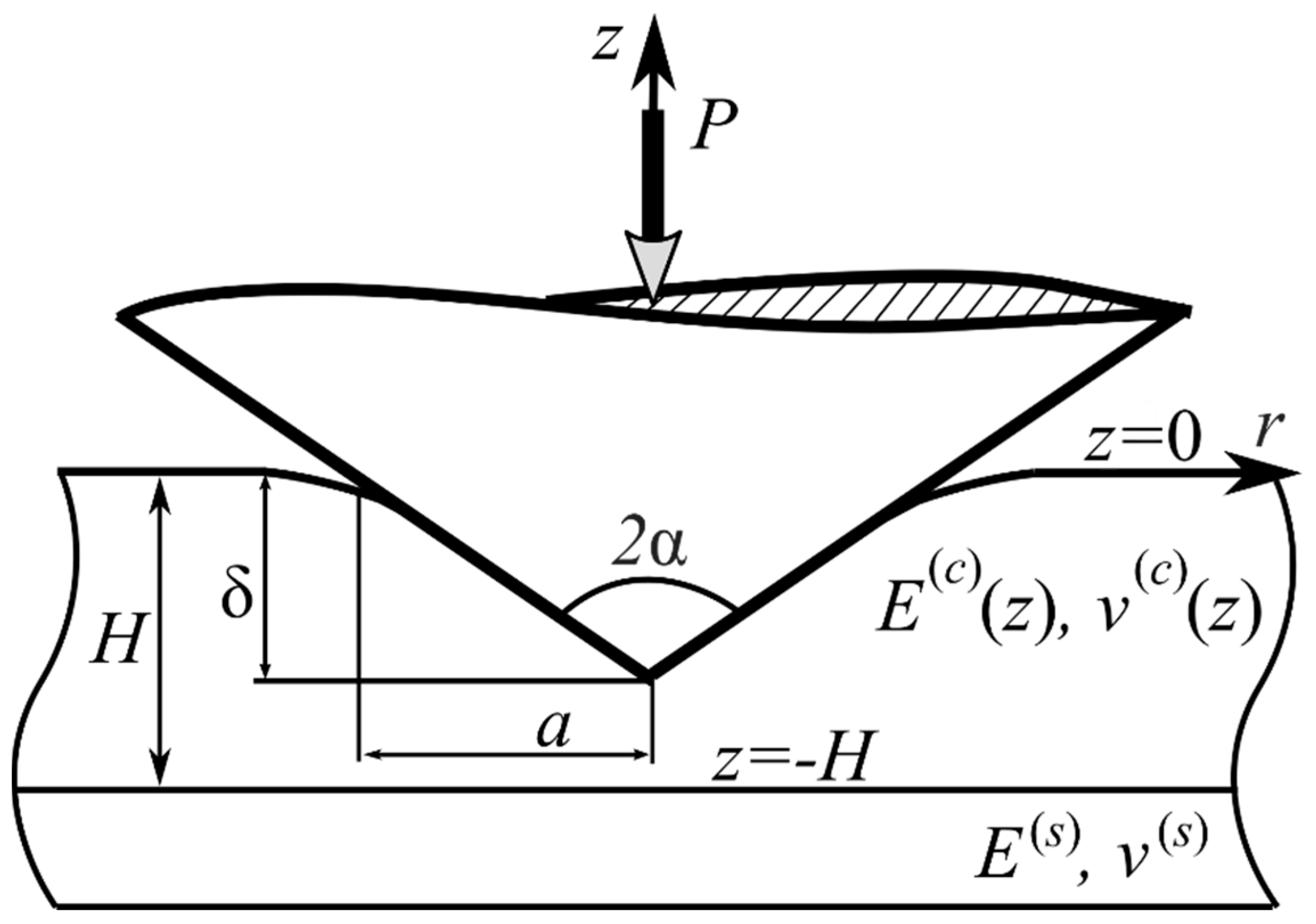
2. Materials and Methods

A non-deformable conical indenter with the angular opening 2α is pressed into the surface of the elastic half-space with a coating of thickness H (Figure 1). Under the normally applied force P, the indenter is displaced into the surface of the coating by the depth δ, while the radius of the contact area is a. Friction forces between the indenter and the half-space are assumed to be absent. A cylindrical coordinate system (r’, φ, z) is associated with the half-space; the z axis is normal to the coating surface z = 0 and passes through the center of the indenter.
Young’s modulus and Poisson’s ratio of the half-space vary with depth according to the continuously differentiable laws independent of each other:
{ E , ν } = { E ( c ) ( z )   , ν ( c ) ( z ) }   ,   H z 0 ; { E ( s ) , ν ( s ) = const } ,   < z < H
Hereinafter, index (c) corresponds to the coating, index (s)—to the substrate. The boundary conditions on the surface of the half-space have the form:
z = 0 : 𝜏 r z = 0 , { σ z = 0 , r > 1 , w = δ + r χ   , r 1
We consider complete adhesion on the coating–substrate interface:
z = H : τ z r ( c ) = τ z r ( s ) ,   σ z ( c ) = σ z ( s ) ,   w ( c ) = w ( s ) , u ( c ) = u ( s )
Following notations are used above: r = r / a is the dimensionless radial coordinate; χ = a cot ( α ) is the contact depth; τ r z и σ z are the components of the stress tensor; u, w are the displacements along the r and z axis. Let us also notate the normal contact stresses as:
σ z | z = 0 = p ( r ) , r 1
Classical continuity condition of the contact stresses at the boundary of the contact area is considered:
p ( 1 ) = 0
The stresses and the displacements vanish at r and z .
Using the integral transformations technique, the problem is reduced [44] to the following integral equation:
0 1 p ( t ) t 0 L ( u ) J 0 ( u r λ ) J 0 ( u t λ ) d u d t = λ E e f ( c ) ( δ r χ ) 2 a ,     r 1
E e f ( c ) = E ( 0 ) / ( 1 ν 2 ( 0 ) ) is effective elastic modulus of the surface of the coating, L(u) is the kernel transform of the integral equation, λ = H / a is the main geometrical parameter of the problem. The scheme of calculation of the kernel transform and analysis of its properties is studied in detail in [47,48].
To solve the problem, let us use the approximated analytical method [39], which allows us to obtain a solution effective for any value of λ. For this purpose, we approximate the function L(u) by the expression:
L ( u ) L N ( u ) = i = 1 N u 2 + A i 2 u 2 + B i 2 ,   A i ,   B i C
We construct the approximation of the kernel transform to satisfy following LN(0) = L(0). Let us introduce the parameter determining the relative elastic properties of the coating in comparison with the substrate:
β = E e f ( s ) E e f ( c ) ,     E e f ( s ) = E ( s ) 1 ( ν ( s ) ) 2
In addition, it was established earlier [48] that the following relation is satisfied.
L N ( 0 ) = L ( 0 ) = β 1
Using the approximation in Equation (7) the solution of the integral Equation (6) is constructed [44] in the following analytical form:
p ( r ) = p hom ( r ) p 0 ( r ) ,         P = P hom P 0
where p hom ( r ) ,   P hom are the solution of the contact problem for the homogeneous half-space without a coating, while p 0 ( r ) ,   P 0 are the dimensionless functions describing the contribution of the coating presence into the solution. These functions have the following form:
p hom ( r ) = E e f ( s ) cot ( α ) 2 arccosh ( 1 r ) ,     P hom = π a E e f ( s ) χ 2
p 0 ( r ) = 1 + i = 1 N ( C i Z s ( r , A i λ 1 ) + D i Z c ( r , A i λ 1 ) arccosh ( r 1 )   )
P 0 = 1 + 2 λ   i = 1 N [ C i A i F ( 1 , λ A i , A i λ ) + D i A i ( λ A i + F ( λ A i , 1 , A i λ ) ) ]
F ( A , B , x ) = A cos h ( x ) + B sin h ( x )
Z { s , c } ( r , A ) = r 1 { sinh ( A t ) , cosh ( A t ) } t 2 r 2 d t
The constants Ci and Di (i = 1,…,N) are determined from the solution of the following system of linear algebraic equations:
i = 1 N D i A i 2 B k 2 = 1 B k 2 ,     i = 1 N C i F ( A i , B k , A i λ 1 ) + D i F ( B k , A i , A i λ 1 ) A i 2 B k 2 = 1 B k
The relationship between the indentation depth and the radius of the contact area is determined by the formula:
δ = δ hom δ 0 ,     δ hom = π a cot ( α ) 2 ,     δ 0 = 1 + i = 1 N λ A i F ( C i , D i , A i λ )
Another important for application characteristic is the indentation stiffness. It is defined as the following derivative: S = dP/dδ. This function is often used [12] for the analysis of the nanoindentation experiments. Taking into account Equations (13) and (17), the following expression for S is obtained:
S = S hom S 0 ,     S hom = 2 a E e f ( s ) ,     S 0 = P 0 ( λ ) δ 0 ( λ )
This value is measured from the indentation experiment as the angle of inclination of the tangent to the unloading curve at a point corresponding to the maximum pressing force.
Let us consider the case N = 1. Then the approximation of the kernel transform has the form:
L ( u ) u 2 + A 2 u 2 + A 2 β ,   A R
Such a simplification makes it possible to solve the system of Equation (16) explicitly. Thus, expressions for p0, P0, δ0 are sufficiently simplified:
p 0 ( r ) = 1 + β 1 1 arccosh ( r 1 ) ( β F ( β , 1 , A λ 1 ) F ( 1 , β , A λ 1 ) Z s ( r , A λ ) + Z c ( r , A λ ) )
P 0 = 1 + 2 λ 2 ( β 1 1 ) ( cosh ( A λ 1 ) 1 ) ( A λ 1 β + 1 ) A 2 F ( 1 , β , A λ 1 )
δ 0 = 1 + λ ( β 1 1 ) ( cosh ( A λ 1 ) 1 ) β A F ( 1 , β , A λ 1 )
The expression of Equation (12), and, as the consequence, all expressions for S0, P0, δ0 for any N, are asymptotically exact for large and small values of λ. For intermediate values of λ, the error of the solution depends on the accuracy of the kernel transform approximation.
An important remark should be made. Expressions p0(r), P0, δ0 and S0 describe the ratio of the indentation force, depth and stiffness observed for the coated half-space to the ones for the homogeneous non-coated half-space. The homogeneous half-space is assumed to have elastic moduli similar to the substrate. We also assume that the contact radius is the same during the comparison, i.e., a = ahom (while indentation force and depth are different). Comparison of the results for the coated and non-coated half-spaces for the same values of the applied indentation force can be easily done using the relationship between the P, δ, S and a. Such a comparison is more convenient for engineering applications. Let us introduce relative variables aP, δP and SP which corresponds to the comparison between the quantities for the coated and non-coated half-spaces made for the same value of the indentation force (i.e., P = Phom). Using Equations (13), (17) and (18), the following expressions are obtained:
a P ( λ ) a a hom | P = P hom = 1 P 0 ( λ ) ,   δ P ( λ ) = δ 0 ( λ ) P 0 ( λ ) ,   S P ( λ ) = P 0 ( λ ) δ 0 ( λ )

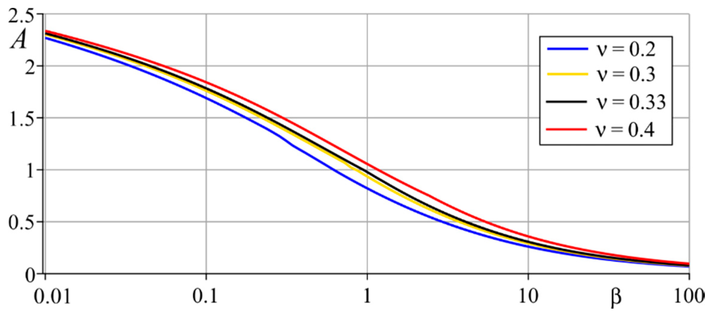
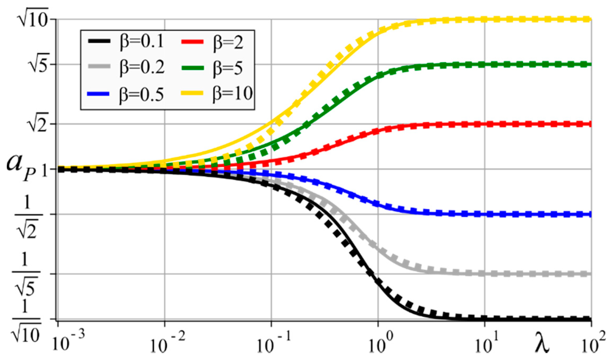
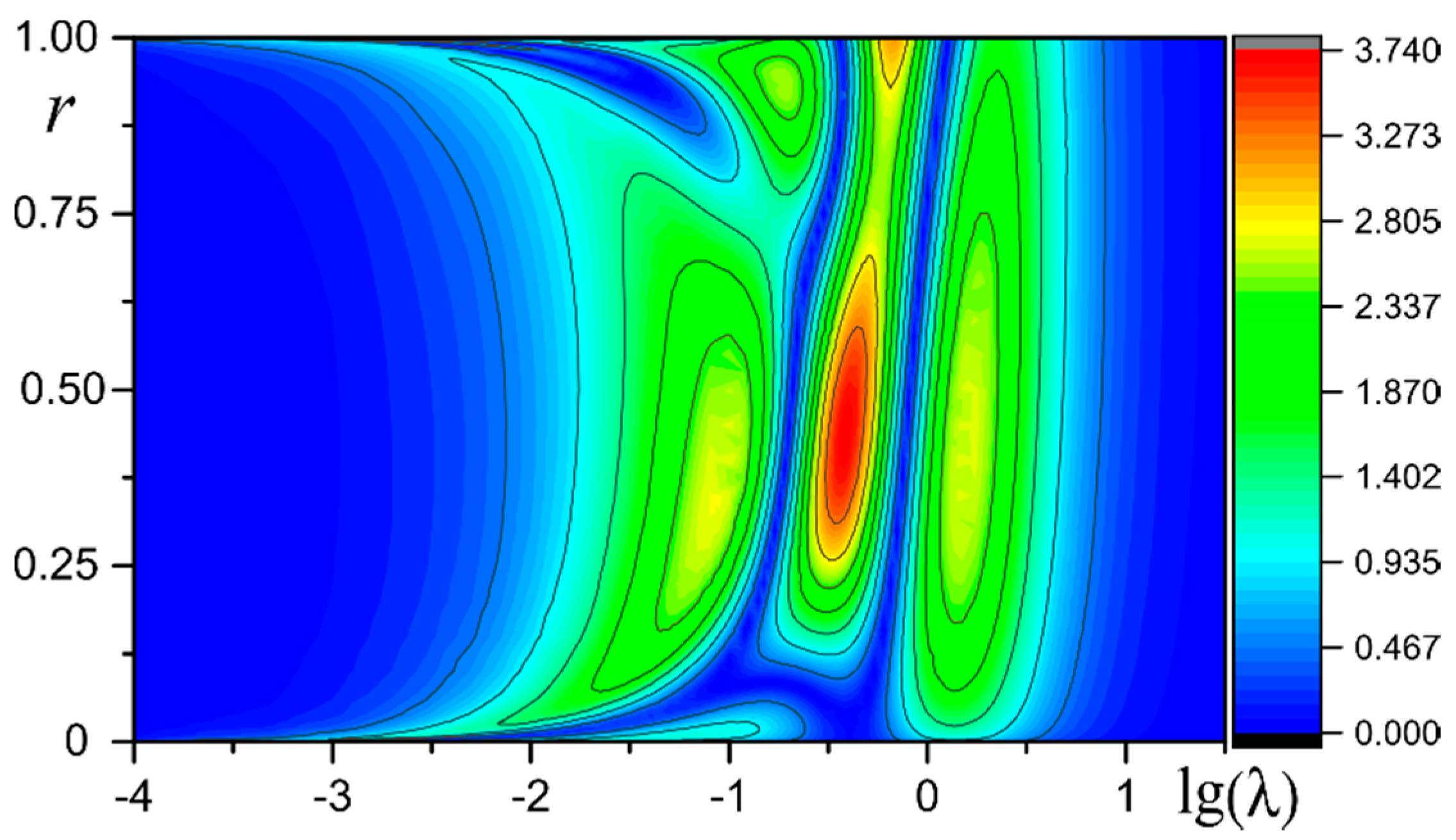
3. Results and Discussion

Let us consider homogeneous coatings and assume that the Poisson’s ratios of the coating and the substrate are equal. Then, kernel transform L(u) has the form:
L ( u ) = a 0 e 4 u 4 ( β 0 + ν 0 ) β 0 u e 2 u ν 1 β 0 2 a 0 e 4 u + ( ( ν 1 2 + 1 ) β 0 + ν 0 2 + 4 ( β 0 + ν 0 ) u 2 ) β 0 e 2 u + ν 1 β 0 2
where β 0 = β 1 ,   ν 0 = 4 ( 1 ν ) ,   ν 1 = 3 4 ν ,   a 0 = ν 1 β 0 2 + ν 0 2 ( β 0 + 1 ) .
Figure 2 shows the dependence of the only parameter A of a simplified (N = 1) approximation (Equation (19)) on a relative Young’s modulus: β = E e f ( s ) / E e f ( c ) = E ( s ) / E ( c ) for different values of the Poisson’s ratio. It is seen that the value of the Poisson’s ratio slightly affects the value of A (in a considered region: 0.2 ≤ ν ≤ 0.4). Accordingly, we only consider the case when ν ( c ) = ν ( s ) = 0.33 . Figure 3 illustrates the dependence of the maximum error of the simplified approximation on β . The approximation error was calculated by the formula:
Δ L ( u ) = | 1 L N ( u ) L ( u ) | 100 %
If the values of the Poisson’s ratio of the coating and substrate are different but still in the region 0.2 ≤ ν ≤ 0.4 then the kernel transform will slightly change from the considered case and all the results below will be similar.
Let us consider a set of homogeneous coatings for which β = 0.1, 0.2, 0.5, 2, 5 and 10. For these coating–substrate systems one-parameter approximations demonstrate the following errors: 18.6, 11.8, 4.24, 4.3, 12.6 and 20.7% correspondingly. At the same time the errors of multi-parameter approximations do not exceed 0.2% (the number of members of multiparameter approximations is in the 17 ≤ N ≤ 21 range).
Figure 4, Figure 5 and Figure 6 illustrate the dimensionless radius of the contact area, indentation depth and stiffness aP, δP, SP related to the similar values for the non-coated homogeneous half-space with the elastic moduli similar to the substrate. The comparison is made for equal indentations forces, i.e., P = Phom. These expressions are defined in Equation (23) and are the functions of parameter λ.
These graphs facilitate an understanding, firstly, of how the presence of a coating affects the indentation stiffness, depth and contact radius and, secondly, of how to estimate the error of the simplified formulas. For λ→0 all these expressions tend to 1, because the solution is asymptotically exact and, obviously, this case describes the non-coated half-space. The case when λ also describe the homogeneous half-space but with the elastic properties similar to the coating.
As we compare the expressions in Equation (23) with the ones for the half-space with elastic properties of the substrate, then expressions SP, aP, δP tends towards different values depending on the value of β . In fact, a P β ,   δ P β ,   S P 1 / β   as λ→∞. It is the consequence of the fact that a, δ and P depend on the square root of the effective elastic modulus.
In addition, the graphs help to evaluate the range of values of the parameter λ for which a significant effect of the presence of coating on these quantities can be observed. For example, for β = 10, the presence of a coating at more than 10% changes the indentation stiffness in the range 0.12 < λ < 4.2, for β = 2 this range is 0.56 < λ < 2.2. The greater the value of β differs from 1, the wider this range. For β > 1, as β increases, this range broadens toward lower λ values. It means that outside this region the classical solution for a homogeneous half-space can be used with the error not exceeding 10%. This fact, in particular, leads to the following conclusion: while measuring the Young’s modulus of a coating in the case when its modulus is significantly different from the one of the substrate, the standard recommendation—to conduct indentation at a depth not exceeding 10% of the coating thickness—may not be accurate and the indentation depth should be significantly less.
To analyze the accuracy of the simplified expressions of SP, aP, δP let us compare these values to the ones obtained using the most accurate approximations of the kernel transform. The relative error is introduced by the following formulas:
Δ { a , S , δ } = | 1 { a , S , δ } N = 1 { a , S , δ } N 1 | 100 %
As an example of the relative error distribution, the dependence of Δ a on parameter λ for β = 0.5 is presented on the Figure 7. All other characteristics Δ { a , S , δ } for any β look pretty similar. They look like three hills standing together. These hills correspond to three ranges of values of λ: ( , λ 0 ) , ( λ 0 , λ 1 ) , ( λ 1 , ) . The values of λ0 and λ1 (different for Δ a , Δ S and Δ δ ) were obtained to satisfy: Δ { a , S , δ } ( λ 0 ) = Δ { a , S , δ } ( λ 1 ) = 0 .
Table 1, Table 2 and Table 3 contain the values of λ0, λ1 and maximum values of Δ { a , S , δ } in these three ranges. Tables show that the error of the simplified expressions for SP, aP, δP is 2–4 times lower than the error of the one-parametric approximation of the kernel transform by the expression in Equation (19). It is also seen, that the maximum error observed in a single region can be much smaller than the total maximum error.
In a similar way let us introduce the relative error function for the distribution of the contact stresses:
Δ p ( r , λ ) = | 1 p ( r ) N = 1 p ( r ) N 1 | 100 %
Maximum values of Δ p ( r , λ ) are 37.01, 15.46, 3.72, 4.42, 13.46 and 23.65% for the homogeneous coatings with β = 0.1, 0.2, 0.5, 2, 5 and 10, respectively. It is seen that the maximum error of the simplified distribution of the contact stresses can be higher than the error of the approximation of the kernel transform but still is of the same order of magnitude.
Figure 8 and Figure 9 contain a 3D plot of Δ p ( r , λ ) for 0.0001 ≤ λ ≤ 100 (logarithmic scale is used) and 0 < r < 1 for β = 0.5 (lower maximum error) and β = 0.1 (higher maximum error). It is seen that the error is concentrated in several regions. The shapes of these regions are very similar, but the distribution of the error is different. For β = 0.5, the error is distributed over all regions much more uniformly than for β = 0.1. The maximum of error is observed in the similar narrow elongated region, located mainly in the range 0.1 ≤ λ ≤ 1 (for β = 0.1, this region is beyond the scope of this range for the small values of r). The maximum error for β = 0.1 in this region is four times higher than the maximum values in other regions (where its value does not exceed 10%). For β = 0.5 the error is only 30% higher than the maximum of other regions. It is seen that for large values of λ expression Δ p ( r , λ ) uniformly tends to 0 for all r as λ→∞. For small λ, the error also tends to 0, but not uniformly. For any small λ narrow regions in the vicinity of r = 0 and r = 1 are observed, where the error is sufficiently larger than outside. With a decrease of λ, these regions become narrower.
Figure 10 illustrates the distribution of the relative contact pressure given by the expressions in Equations (12) and (20) for the coatings with β = 0.5 and β = 2. Good agreement for all relative thicknesses of the coating is observed between the simplified solution and a much more accurate solution for N >> 1.
It should be also pointed out that, for the vast majority of real combinations of coating and substrate materials, parameter β lies in the range 0.3 ≤ β ≤ 3. The cases of β = 0.2 or β = 5 correspond to a combination of one of the softest and hardest metals, like aluminum (Al) and tungsten (W). Such combinations are rare in practice.

4. Conclusions

The main result of this paper consists in the construction of an explicit analytical solution for the conical indentation contact problem in the simplest possible form, suitable for analysis of the indentation experiments of coated materials, e.g., for evaluation of the Young’s modulus of a thin coating. The detailed analysis of the ranges of geometrical and elastic parameters, for which the presence of the coating sufficiently influences the contact characteristics, was provided. These results enable the evaluation of whether the classical Sneddon’s solution is suitable for analysis of elastic properties from indentation experiments or more complicated models taking into account both coating and substrate responses should be used.
The error of the simplified solution was also analyzed in detail. The analysis showed high accuracy of the simplified expressions for the relations between the indentation stiffness, force, depth and contact radius for any value of relative thickness of the coating even in a case when the elastic moduli of the coating and substrate differ at an order of magnitude. The simplified distribution of the contact stresses demonstrated high accuracy for a relatively small ratio of the elastic moduli of the coating and substrate. If the ratio of the elastic moduli is high (β ≥ 3), then the simplified distribution of the contact stresses may be inaccurate in a range 0.1 < λ < 1 and for smaller λ in the small vicinities of the center and boundary of the contact area.
Besides nanoindentation, the solution could also be applied to other engineering backgrounds, such as, for example, high-speed railway systems [49,50].

Author Contributions

Conceptualization, A.S.V.; software, S.S.V. and E.V.S.; validation, E.V.S.; formal analysis, S.S.V.; investigation, E.V.S.; data curation, A.S.V.; writing—original draft preparation, A.S.V.; methodology, A.S.V.; writing—review and editing, A.S.V.; visualization, E.V.S.; project administration, S.M.A.; funding acquisition, S.M.A.; supervision, S.M.A. All authors have read and agreed to the published version of the manuscript.

Funding

This work was supported by the Government of the Russian Federation (grant No. 14.Z50.31.0046).

Conflicts of Interest

The authors declare no conflict of interest.

References

  1. Asri, R.I.M.; Harun, W.S.W.; Samykano, M.; Lah, N.A.C.; Ghani, S.A.C.; Tarlochan, F.; Raza, M.R. Corrosion and surface modification on biocompatible metals: A review. Mater. Sci. Eng. C 2017, 77, 1261–1274. [Google Scholar] [CrossRef] [PubMed] [Green Version]
  2. Xue, Y.; Wang, S.; Bi, P.; Zhao, G.; Jin, Y. Super-Hydrophobic Co–Ni Coating with High Abrasion Resistance Prepared by Electrodeposition. Coatings 2019, 9, 232. [Google Scholar] [CrossRef] [Green Version]
  3. Yang, J.; Odén, M.; Johansson-Jõesaar, M.P.; Esteve, J.; Llanes, L. Mechanical strength of ground WC-Co cemented carbides after coating deposition. Mater. Sci. Eng. A 2017, 689, 72–77. [Google Scholar] [CrossRef] [Green Version]
  4. Elkhoshkhany, N.; Hafnway, A.; Khaled, A. Electrodeposition and corrosion behavior of nano-structured Ni-WC and Ni-Co-WC composite coating. J. Alloy. Compd. 2017, 695, 1505–1514. [Google Scholar] [CrossRef]
  5. Zelentsov, V.B.; Mitrin, B.I.; Lubyagin, I.A. Wear resistance of coating materials under the frictional heating conditions. J. Frict. Wear 2017, 38, 265–271. [Google Scholar] [CrossRef]
  6. Warcholinski, B.; Gilewicz, A.; Kuprin, A.S.; Tolmachova, G.N.; Ovcharenko, V.D.; Kuznetsova, T.A.; Lapitskaya, V.A.; Chizhik, S.A. Comparison of mechanical and tribological properties of nitride and oxynitride coatings based on chrome and zirconium obtained by cathodic arc evaporation. J. Frict. Wear 2019, 40, 163–170. [Google Scholar] [CrossRef]
  7. Yuan, Z.; Tao, B.; He, Y.; Liu, J.; Lin, C.; Shen, X.; Ding, Y.; Yu, Y.; Mu, C.; Liu, P.; et al. Biocompatible MoS2/PDA-RGD coating on titanium implant with antibacterial property via intrinsic ROS-independent oxidative stress and NIR irradiation. Biomaterials 2019, 217, 119290. [Google Scholar] [CrossRef]
  8. Mandracci, P.; Mussano, F.; Rivolo, P.; Carossa, S. Surface treatments and functional coatings for biocompatibility improvement and bacterial adhesion reduction in dental implantology. Coatings 2016, 6, 7. [Google Scholar] [CrossRef] [Green Version]
  9. Golovin, Y.I. Nanoindentation and Its Capabilities; Mashinostroenie: Moscow, Russia, 2009; pp. 8–32. (In Russian) [Google Scholar]
  10. Ogbonna, N.; Needleman, A. Conical indentation of thick elastic spherical shells. J. Mech. Mater. Struct. 2011, 6, 443–451. [Google Scholar] [CrossRef] [Green Version]
  11. Taljat, B.; Zacharia, T.; Pharr, G.M. Pile-up behavior of spherical indentations in engineering materials. In Fundamentals of Nanoindentation and Nanotribology; Moody, N.R., Gerberich, W.W., Burnham, N., Baker, S.P., Eds.; Materials Research Society: Warrendale, PA, USA, 1998; Volume 522, p. 33. [Google Scholar]
  12. Oliver, W.C.; Pharr, G.M. An improved technique for determining hardness and elastic modulus using load and displacement sensing indentation experiments. J. Mater. Res. 1992, 7, 1564–1583. [Google Scholar] [CrossRef]
  13. Oliver, W.C.; Pharr, G.M. Measurement of hardness and elastic modulus by instrumented indentation: Advances in understanding and refinements to methodology. J. Mater. Res. 2004, 19, 3–20. [Google Scholar] [CrossRef]
  14. Sneddon, I.N. The relation between load and penetration in the axisymmetric Boussinesq problem for a punch of arbitrary profile. Int. J. Eng. Sci. 1965, 3, 47–57. [Google Scholar] [CrossRef]
  15. ISO 14577-1:2015. Metallic Materials—Instrumented Indentation Test for Hardness and Materials Parameters—Part 1: Test Method. Available online: https://www.iso.org/standard/56626.html (accessed on 13 May 2020).
  16. Field, J.S.; Swain, M.V. Determining the mechanical properties of small volumes of material from submicrometer spherical indentations. J. Mater. Res. 1995, 10, 101–112. [Google Scholar] [CrossRef]
  17. Buckle, H. The Science of Hardness Testing and Its Research Applications; American Society for Metals: Cleveland, OH, USA, 1973; pp. 453–491. [Google Scholar]
  18. Chen, J.; Bull, S.J. On the factors affecting the critical indenter penetration for measurement of coating hardness. Vacuum 2009, 83, 911–920. [Google Scholar] [CrossRef]
  19. Veprek-Heijman, M.G.; Veprek, S. The deformation of the substrate during indentation into superhard coatings: Bückle’s rule revised. Surf. Coat. Technol. 2015, 284, 206–214. [Google Scholar] [CrossRef]
  20. Manika, I.; Maniks, J. Effect of substrate hardness and film structure on indentation depth criteria for film hardness testing. J. Phys. D Appl. Phys. 2008, 41, 074010. [Google Scholar] [CrossRef]
  21. Chen, W.; Xu, K.; Tao, B.; Dai, L.; Yu, Y.; Mu, C.; Shen, X.; Hu, Y.; He, Y.; Cai, K. Multilayered coating of titanium implants promotes coupled osteogenesis and angiogenesis in vitro and in vivo. Acta Biomater. 2018, 74, 489–504. [Google Scholar] [CrossRef]
  22. Go, A.; Kim, H.T.; Park, Y.J.; Park, S.R.; Lee, M.H. Fabrication of Repeatedly Usable Pt-Electrode Chip Coated With Solidified Glucose Oxidase and Ascorbate Oxidase for the Quantification of Glucose in Urine. IEEE Sens. Lett. 2019, 3, 1–4. [Google Scholar] [CrossRef]
  23. Mohanty, A.; Gangopadhyay, S.; Thakur, A. On applicability of multilayer coated tool in dry machining of aerospace grade stainless steel. Mater. Manuf. Process. 2016, 31, 869–879. [Google Scholar] [CrossRef]
  24. Nikitin, V.I.; Smyslov, A.M.; Lisyansky, A.S.; Smyslova, M.K.; Simin, O.N.; Shelyapina, N.M. Corrosion resistance of nitride coatings of steam turbine blades. Therm. Power Eng. 2009, 2, 2–6. (In Russian) [Google Scholar]
  25. Sneddon, I.N. Fourier Transforms; McGraw-Hill: New York, NY, USA, 1951. [Google Scholar]
  26. Gladwell, G.M.L. Contact Problems in the Classical Theory of Elasticity; Springer Science & Business Media: Berlin/Heidelberg, Germany, 1980. [Google Scholar]
  27. Alexandrov, V.M.; Pozharskii, D.A. Three-Dimensional Contact Problems; Solid Mechanics and Its Applications; Springer Science & Business Media: Berlin/Heidelberg, Germany, 2001. [Google Scholar]
  28. Vorovich, I.I.; Ustinov, I.A. Pressure of a die on an elastic layer of finite thickness. J. Appl. Math. Mech. 1959, 23, 637–650. [Google Scholar] [CrossRef]
  29. Alexandrov, V.M. Asymptotic solution of the contact problem for a thin elastic layer. J. Appl. Math. Mech. 1969, 33, 49–63. [Google Scholar] [CrossRef]
  30. Zelentsov, V.B.; Lapina, P.A.; Mitrin, B.I.; Eremeyev, V.A. Characterization of the functionally graded shear modulus of a half-space. Mathematics 2020, 8, 640. [Google Scholar] [CrossRef] [Green Version]
  31. Zelentsov, V.B.; Sakhabudinov, R.V. Uniform motion of a plane punch on the boundary of an elastic half-plane. Mech. Solids 2014, 49, 208–217. [Google Scholar] [CrossRef]
  32. Zelentsov, V.B.; Lapina, P.A.; Mitrin, B.I.; Kudish, I.I. An antiplane deformation of a functionally graded half-space. Contin. Mech. Thermodyn. 2019. [Google Scholar] [CrossRef]
  33. Popov, G.I. On the method of orthogonal polynomials in contact problems of the theory of elasticity. J. Appl. Math. Mech. 1969, 33, 503–517. [Google Scholar] [CrossRef]
  34. Liu, T.J.; Wang, Y.S.; Xing, Y.M. The axisymmetric partial slip contact problem of a graded coating. Meccanica 2012, 47, 1673–1693. [Google Scholar] [CrossRef]
  35. Guler, M.A.; Erdogan, F. Contact mechanics of two deformable elastic solids with graded coatings. Mech. Mater. 2006, 38, 633–647. [Google Scholar] [CrossRef]
  36. Su, J.; Ke, L.L.; Wang, Y.S. Axisymmetric frictionless contact of a functionally graded piezoelectric layered half-space under a conducting punch. Int. J. Solids Struct. 2019, 90, 45–59. [Google Scholar] [CrossRef]
  37. Ke, L.L.; Yang, J.; Kitipornchai, S.; Wang, Y.S. Electro-mechanical frictionless contact behavior of a functionally graded piezoelectric layered half-plane under a rigid punch. Int. J. Solids Struct. 2008, 45, 3313–3333. [Google Scholar] [CrossRef] [Green Version]
  38. Su, J.; Ke, L.-L.; Wang, Y.-S.; Xiang, Y. The axisymmetric torsional contact problem of a functionally graded piezoelectric coated half-space. Acta Mech. Sin. 2017, 33, 406–414. [Google Scholar] [CrossRef]
  39. Vasiliev, A.S.; Volkov, S.S.; Aizikovich, S.M. Approximated Analytical Solution of a Problem on Indentation of an Electro-Elastic Half-Space with Inhomogeneous Coating by a Conductive Punch. Doklady Phys. 2018, 63, 18–22. [Google Scholar] [CrossRef]
  40. Wang, L.; Rokhlin, S.I. Universal scaling functions for continuous stiffness nanoindentation with sharp indenters. Int. J. Solids Struct. 2005, 42, 3807–3832. [Google Scholar] [CrossRef]
  41. Ogasawara, N.; Chiba, N.; Chen, X. Representative strain of indentation analysis. J. Mater. Res. 2005, 20, 2225–2234. [Google Scholar] [CrossRef]
  42. Vasiliev, A.S.; Swain, M.V.; Aizikovich, S.M.; Sadyrin, E.V. Torsion of a circular punch attached to an elastic half-space with a coating with periodically depth-varying elastic properties. Arch. Appl. Mech. 2016, 86, 1247–1254. [Google Scholar] [CrossRef]
  43. Vasiliev, A.S.; Volkov, S.S.; Belov, A.A.; Litvinchuk, S.Y.; Aizikovich, S.M. Indentation of a hard transversely isotropic functionally graded coating by a conical indenter. Int. J. Eng. Sci. 2017, 112, 63–75. [Google Scholar] [CrossRef]
  44. Aizikovich, S.M.; Vasil’ev, A.S.; Volkov, S.S. The axisymmetric contact problem of the indentation of a conical punch into a half-space with a coating inhomogeneous in depth. J. Appl. Math. Mech. 2015, 79, 500–505. [Google Scholar] [CrossRef]
  45. Sadyrin, E.V.; Vasiliev, A.S.; Volkov, S.S.; Mitrin, B.I.; Aizikovich, S.M. Simplified analytical solution of the contact problem on indentation of a coated half-space by a spherical punch. WIT Trans. Eng. Sci. 2019, 122, 209–221. [Google Scholar]
  46. Vasiliev, A.S.; Sadyrin, E.V.; Volkov, S.S.; Kislyakov, E.A.; Sevostianov, I. Construction of the simplified analytical solution of the flat punch indentation contact problem. AIP Conf. Proc. 2019, 2188, 040017. [Google Scholar]
  47. Vasiliev, A.S. Compliance functions of electromagnetoelastic piezoelectric and piezomagnetic half-plane and half-space with functionally graded or layered coatings. J. Samara State Tech. Univ. Ser. Phys. Math. Sci. 2019, 23, 475–496. [Google Scholar]
  48. Volkov, S.S.; Vasiliev, A.S.; Aizikovich, S.M.; Sadyrin, E.V. Compliance functions for a thermoelastic FGM coated half-plane with incomplete adhesion between the coating and substrate. J. Phys. Conf. Ser. 2020, 1474, 012034. [Google Scholar] [CrossRef] [Green Version]
  49. Song, Y.; Liu, Z.; Ronnquist, A.; Navik, P.; Liu, Z. Contact Wire Irregularity Stochastics and Effect on High-speed Railway Pantograph-Catenary Interactions. IEEE Trans. Instrum. Meas. 2020. [Google Scholar] [CrossRef]
  50. Peng, B.; Iwnicki, S.; Shackleton, P.; Song, Y. General conditions for railway wheel polygonal wear to evolve. Veh. Syst. Dyn. 2019. [Google Scholar] [CrossRef]
Figure 1. The scheme of the contact problem.
Mathematics 08 00983 g001
Figure 2. Dependence of a parameter A of the simplified approximation of the kernel transform on a relative Young’s modulus β for ν(s) = ν(c).
Mathematics 08 00983 g002
Figure 3. Graphs of a maximum relative error max(ΔL(u)) of the simplified approximation of the kernel transform versus relative elastic parameter β.
Mathematics 08 00983 g003
Figure 4. Relative contact radius aP for the homogeneous coatings calculated with N >> 1 (solid lines) and N = 1 (dashed lines).
Mathematics 08 00983 g004
Figure 5. Relative indentation depth δP for the homogeneous coatings calculated with N >> 1 (solid lines) and N = 1 (dashed lines).
Mathematics 08 00983 g005
Figure 6. Relative indentation stiffness SP for the homogeneous coatings calculated with N>>1 (solid line) and N = 1 (dashed line).
Mathematics 08 00983 g006
Figure 7. Graph of the relative error Δa of a simplified expression aP versus relative coating thickness λ for β = 0.5.
Mathematics 08 00983 g007
Figure 8. The relative error Δp(r,λ) of the simplified distribution of the contact stresses for β = 0.5 in %.
Mathematics 08 00983 g008
Figure 9. The relative error Δp(r,λ) of the simplified distribution of the contact stresses for β = 0.1 in %.
Mathematics 08 00983 g009
Figure 10. Relative contact pressure for the coatings of different relative thickness λ calculated with N >> 1 (solid lines) and N = 1 (dotted lines): (a) β = 0.5; (b) β = 2.
Mathematics 08 00983 g010
Table 1. Maximum relative error ΔS of the simplified expression SP in different ranges of λ.
β = 0.1 β = 0.2 β = 0.5 β = 2β = 5β = 10
λ 0 0.280.360.50.520.380.31
λ 1 6.83.31.851.652.64.7
max < λ < λ 0 Δ S , %1.681.490.951.645.088.99
max λ 0 < λ < λ 1 Δ S , %6.422.980.560.462.284.58
max λ 1 < λ < Δ S , %0.490.880.620.430.380.18
Table 2. Maximum relative error Δa of the simplified expression aP in different ranges of λ.
β = 0.1 β = 0.2 β = 0.5 β = 2β = 5β = 10
λ 0 0.090.140.220.250.210.18
λ 1 0.90.880.840.951.151.35
max < λ < λ 0 Δ a , %1.421.350.951.695.068.62
max λ 0 < λ < λ 1 Δ a , %7.234.111.171.113.76.39
max λ 1   < λ < Δ a , %4.563.111.210.720.940.82
Table 3. Maximum relative error Δδ of the simplified expression δP in different ranges of λ.
β = 0.1 β = 0.2 β = 0.5 β = 2β = 5β = 10
λ 0 0.270.360.50.520.390.31
λ 1 6.23.31.881.72.64.7
max < λ < λ   0 Δ δ , %1.711.510.961.614.98.5
max λ 0 < λ < λ 1 Δ δ , %6.032.890.550.462.334.8
max λ 1 < λ < Δ δ , %0.490.890.620.430.380.18

