1. Introduction
As structures or structural components, elastic membranes have played important roles in many fields. For instance, the vesicle membrane for targeted drug delivery [
1] and cell membrane adhered onto substratum [
2] are of practical importance in biological science, the electrostatically driven diaphragm membranes play important roles in micro-electro-mechanical systems (MEMS) [
3,
4], and the membrane structures in bulge tests [
5,
6,
7] or blister tests [
8,
9,
10,
11,
12,
13,
14] are designed for characterizing the mechanical properties of thin films or film/substrate interfaces.
Analysis of large deflection of a clamped circular elastic deformed isotropic membrane gained much attention due to the axisymmetric characteristic convenient to be dealt with analytically [
15,
16,
17,
18,
19,
20,
21]. The famous German scientist Hencky, originally solved the problem of axisymmetric deformation of an initially flat peripherally fixed transversely uniformly loaded circular membrane, and presented the power series solution of the problem in 1915 [
22]. A computational error in [
22] was corrected by Chien [
23] and Alekseev [
24], respectively. This well-known problem is usually called the Föppl–Hencky membrane problem, or simply, the well-known Hencky problem, because Hencky started the solution to this problem from a bending problem of a thin plate, and based on the simple understanding that the “membrane” is naturally very thin and flexible, ignoring the bending related terms in the Föppl-von Kármán large deflection equations for thin plates. The solution of this problem is usually called the well-known Hencky solution, and is often cited in the studies of related issues [
6,
9,
10,
15,
16,
17,
18,
19,
20,
21]. The well-known Hencky solution is actually only for uniform lateral loading because the uniform loads act only in the vertical (transverse) direction perpendicular to the initially flat circular membrane and no loads act in the horizontal direction parallel to the initially flat circular membrane, that is, there is no in-plane loading. To compare the uniform lateral loading with the uniform pressure loading, Fichter [
25] reformulated the problem, which was dealt with originally by Hencky, with replacing the uniform lateral loading by the uniform pressure loading, and presented the power series solution of the boundary value problem for uniform pressure loading. The difference between the uniform lateral loading solution (i.e., the well-known Hencky solution which may be found in [
15]) and the uniform pressure loading solution was found to be small for lightly loaded membranes and substantially obvious for heavily loaded membranes [
25]. In fact, the uniform lateral loading usually refers to the self-weight of structural members, or simply gravity loading, also known as the uniformly distributed transverse loads, which is always downward. While the uniform pressure loading usually refers to the surface loads resulting from, for example, pressurized gas, also known as the uniformly distributed normal loads, which is always perpendicular to the surface of the deformed membrane.
On the other hand, if the uniform pressure is applied on one side of an initially flat peripherally fixed circular membrane, such that the circular membrane deflects axisymmetrically and comes into contact with a flat surface parallel to the initially flat circular membrane, then this is the so-called contact problem between circular membranes and rigid plates [
26,
27,
28]. Such a contact problem is also reminiscent of the constrained blister test [
11,
12], but the debonding does not occur at the edge of the blistering film, because the edge of the blister is clamped. The contact and adhesion between the membrane and the rigid plate usually gained much attention [
26,
27]. Plaut et al. [
26] analyzed the effect of the work of adhesion on the contact radius of a pressurized blister with a flat surface, where the thin blistering film was considered as a linear plate model (with stretching resistance neglected), as a nonlinear plate model (including both bending and stretching resistance), and as a membrane model (with bending resistance neglected), respectively. The linear plate models have the analytical solutions of the deflection and the total energy, while the other two had to be solved numerically using a shooting method due to the involved, somewhat intractable, nonlinear differential equations. Xu and Liechti [
27] presented an analytical and experimental study on this contact problem and were intended to develop analytical solutions in order to predict the relationship among the contact radius, contact force, and the pressure for simplicity. In [
27], this contact problem was formulated and its analytical solution was obtained based on the four made assumptions: (i) the flexural rigidity of the thin film is negligible and thus only the membrane stresses need to be considered; (ii) the gap
g between the initially flat circular membrane and the constrained rigid plate is far from the radius of the circular membrane, and the rotation angle
of the deflected circular membrane is so small that
holds; (iii) a constant radial stress is assumed; (iv) a frictionless contact between the film and the rigid surface is assumed. While Wang et al. [
28] reformulated this contact problem under the condition of abandoning the constant radial stress assumption adopted in [
27] and presented a power series solution of the problem. The computational accuracy of the solution presented in [
28] is indeed improved in comparison with that of the solution presented in [
27].
However, the solutions presented in both [
27,
28] are actually only for uniform lateral loading, because during the derivation of the solutions presented in [
27,
28], only the vertical (i.e., the transverse direction perpendicular to the initially flat circular membrane) component of the applied uniform pressure acting on the deflected membrane was taken into account and the horizontal component was neglected. Therefore, the uniform pressure loading is just said and actually not considered in [
27,
28]. Just as mentioned above, however, the solution for uniform lateral loading is usually for the problem from the self-weight of structural members, or simply the structural problem by gravity loading. Obviously, the circular membrane here is usually very light, thus its self-weight could be neglected. In particular, when conducting a contact experiment, it is usually difficult to increase the uniform lateral loads applied on the deflected membrane, but easy to increase the surface normal loads by pressurized gas. Therefore, the key issue addressed in [
27,
28] should be to develop the analytical solution suitable for uniform pressure loading (rather than uniform lateral loading), which is exactly what we here want to solve.
In the present study, the membrane theory for uniform pressure loading developed by Fichter [
25] is employed to develop the closed-form solution suitable for the static contact problem addressed here. In the following section, the membrane equations are established based on Fichter’s membrane theory, the power series method was employed to solve the boundary value problem of the resulting nonlinear differential equation, and a closed-form solution of the problem addressed here was finally presented. Then some important issues such as the effectiveness of the solution obtained in
Section 2, as well as the difference between the solutions presented in this study and in [
28], are discussed in
Section 3. Concluding remarks are presented in
Section 4.
2. Membrane Equation and Its Solution
Suppose that, an initially flat and unstressed, linearly elastic, circular isotropic membrane with Poisson’s ratio
v, Young’s modulus
E, thickness
h, and radius
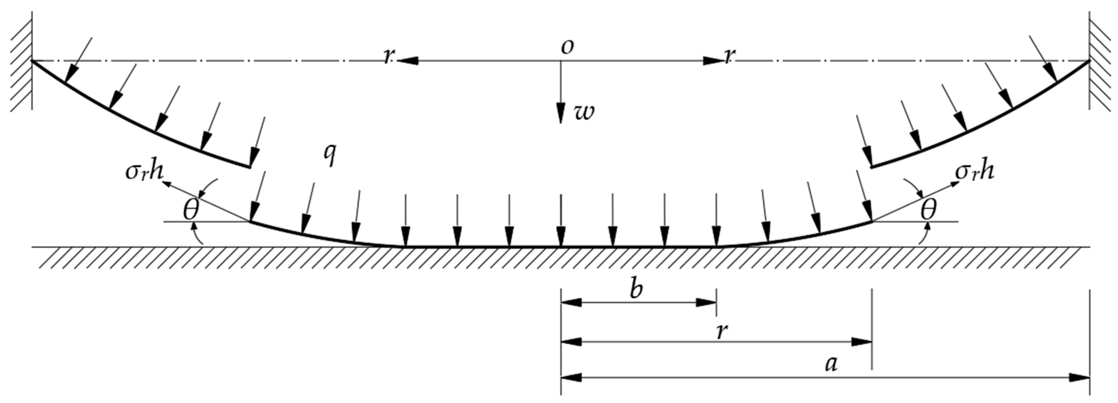
a is clamped at its outer edge and then is pressurized on one side of the membrane by gas, such that it comes into contact with a frictionless flat surface of a rigid plate being parallel to the initially flat membrane, resulting in a restriction on the maximum deflection of the deformed circular membrane, as depicted in
Figure 1, where the dash-dotted line denotes the geometrically middle plane of the circular membrane before deflection,
q denotes the gas pressure acting on the surface of the circular membrane,
r denotes the radial coordinate of the cylindrical coordinate system
(where the polar coordinate system
is located in the plane in which the geometrically middle plane of the initially flat circular membrane is located),
w denotes the transverse coordinate of the system
as well as the transverse displacement of the deformed circular membrane,
a is the radius of the circular membrane,
b is the contact radius between the deformed circular membrane and the frictionless rigid plate, and
g is the gap between the initially flat circular membrane and the frictionless rigid plate. The whole deformed circular membrane can be divided into two parts, that is, the central contact portion concerning the plane problem of axisymmetric deformation of the plane radial stretched or compressed membrane in the circular region 0 ≤
r ≤
b, and the outer non-contact portion concerning the large deflection problem of axisymmetric deformation of the membrane in the annular region
b ≤
r ≤
a. So, this contact problem should be addressed by the simultaneous solution to the two successive local problems, where the continuous conditions at
r = b and the boundary conditions at
r =
a will be used for determining the special solutions of the stress and deflection of the deformed circular membrane. As for the problem before the deflected membrane comes into contact with the frictionless rigid plate, its solution may be found in [
25].
Let us address firstly the large deflection problem of axisymmetric deformation of the membrane in the annular region
b ≤
r ≤
a, and take a piece of the deformed circular membrane with radius
b ≤ r ≤
a, with a view of studying the static problem of equilibrium of this piece of the deformed circular membrane under the joint actions of the gas pressure
q acting on the surface of the circular membrane, the membrane force
acting on the boundary
r, and the reaction force
from the frictionless rigid plate, as depicted in
Figure 2, where
represents the radial stress and
represents the slope angle of the deflected circular membrane. Obviously, right here there are two vertical forces acting on the deformed circular membrane with radius
r (
b ≤
r ≤
a), i.e., the total vertical force
which is produced by the membrane force
, and the total vertical force which is produced by the gas pressure
q and is usually approximated as
[
25]. So, the usually so-called out-of-plane equilibrium equation may approximately be written as
where:
Substituting Equation (2) into Equation (1), one has
The so-called in-plane equilibrium equation may approximately be written as [
25]
where
is the circumferential stress. The relations between strain and displacement for the large deflection problem are
and
where
denotes the radial strain,
denotes the circumferential strain, and
u denotes the radial displacement. The relations between stress and strain are
and
Substitute Equations (5) and (6) into Equations (7) and (8)
and
From Equations (4), (9), (10), one has
If we substitute
u of Equation (11) into Equation (9), we can obtain the compatibility equation
Furthermore, let us address the plane problem of axisymmetric deformation of the plane radial stretched or compressed circular membrane in the central contact region
0 ≤
r ≤
b, where the radial displacement at
r =
b is denoted by
. It is obvious that
when
0 ≤
r ≤
b because the slope angle of the membrane is zero in this region, i.e.,
when
0 ≤
r ≤
b. So, after substituting
into Equations (5), (9) and (10), it may be found that
and
Substituting Equations (14) and (15) into Equation (4) and using
, we obtain an equation containing only the radial displacement
uObviously Equation (16) satisfies the form of the Euler equation, and it is not difficult for us to obtain its general solution
, where
and
are two undetermined constants. Now let us address the conditions to determine
and
, or the conditions that the special solution of Equation (16) must satisfy. According to the characteristics of the physical phenomenon of axisymmetric deformation of the plane radial stretched or compressed circular membrane in the central contact region 0 ≤
r ≤
b, it is not difficult for us to understand that the radial displacement is equal to zero at the center of the circular membrane, that is
Moreover, at
r =
b, the radial displacement is denoted by
, that is
Therefore, from Equation (17), we know that
must be equal to zero to make sure that the value of the radial displacement
u is finite at
r = 0, and further, from Equation (18), we can obtain
. Then, the special solution of Equation (16) may be written as
Substituting Equation (19) into Equations (6), (13)–(15), it may finally be found that
and
Equations (20) and (21) indicate that the strain and stress are uniformly distributed in the central contact region 0 ≤ r ≤ b.
Now, let us address the boundary conditions at
r =
a and the continuous conditions at
r = b for the large deflection problem of axisymmetric deformation of the membrane in the annular region
b ≤ r ≤
a. The boundary conditions at
r =
a are
and
The continuous conditions at
r =
b are
and
where
and
represent the values of various variables on the two sides of the inter-connecting circle of
r =
b, and the subscript
A refers to the annular region
b ≤
r ≤
a, while the subscript
B refers to the circular region 0 ≤
r ≤
b. In addition, from the above discussion on the plane problem, we know that
at
r =
b.
We introduce the following nondimensional variables
Transform Equations (3), (12), (22)–(26) into
and
Eliminating
from Equations (28) and (29), a differential equation which contains only
is obtained
Letting
and expanding
and
into the power series of the
, i.e., letting
and
After substituting Equation (36) into Equation (35), the coefficients
can be expressed into the polynomial of
and
, which are shown in
Appendix A, and after that, substituting Equations (36) and (37) into Equation (28), the coefficients
can also be expressed into the polynomial of
and
, which are shown in
Appendix B. There still is another undetermined constant
, besides the undetermined constant
and
.
All the undetermined constants can be determined by applying the boundary conditions and continuous conditions. From Equations (36) and (37), Equation (30) gives
From Equation (37), Equations (31) and (32) give
and
From Equations (36) and (37), Equation (33) gives
From Equation (36), Equation (34) gives
Equation (40) minus Equation (39) yields
Eliminating the
from Equations (41) and (42), one has
Therefore, for the given problem where a, h, g, v, E, and q are known in advance, the undetermined constants , and the contact radius b can be determined by Equations (38), (43), and (44). So, with the known , , and b, all the coefficients and can be determined, and further, with the known , the undetermined constant can be determined by Equation (39). Thus, the problem addressed here can be solved.
3. Results and Discussion
Let us firstly see whether there are any errors during the derivation in
Section 2. Obviously, before and after the moment that the deformed circular membrane just touched the frictionless rigid plate, the shape of the deformed circular membrane changes very little, and the problem after the deformed circular membrane comes into contact with the frictionless rigid plate is the contact problem addressed in
Section 2, while the problem before the deformed circular membrane touches the frictionless rigid plate is exactly the one dealt with in [
25]. So, the solution presented in [
25] could be used for identifying the effectiveness of the closed-form solution presented in
Section 2.
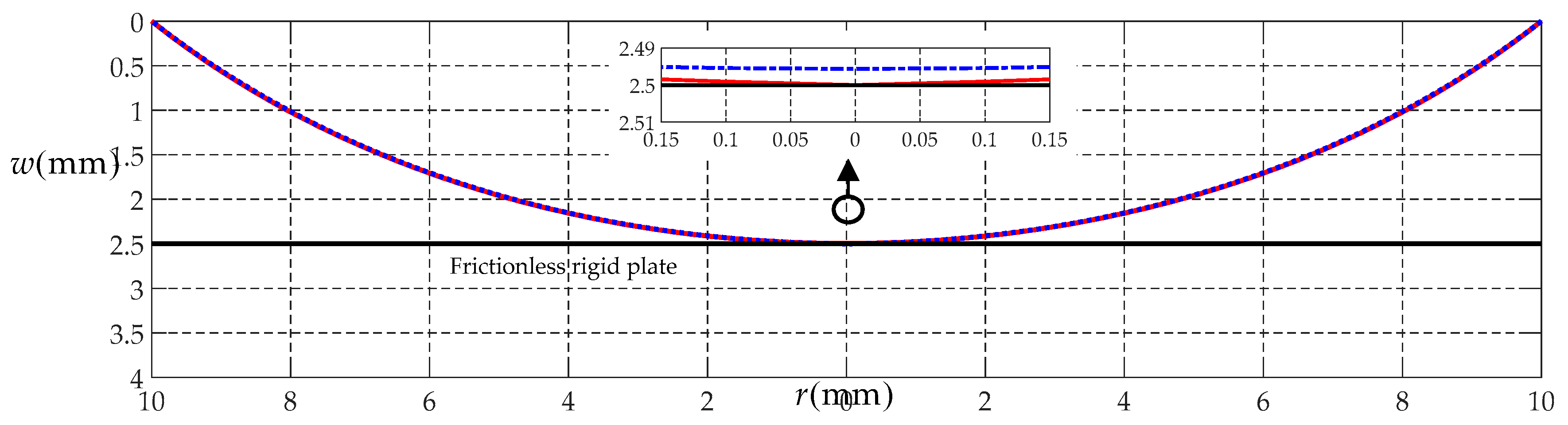
To this end, let us consider a numerical example of a circular rubber membrane with
a = 10 mm,
h = 1 mm,
E = 7.84 MPa, and
v = 0.47. The maximum deflection of the membrane is about 2.495 mm when the circular rubber membrane is subjected to a gas pressure of
q = 0.0554 MPa, which is obtained by using the solution presented in [
25]. Suppose that, the gap
g between the initially flat circular rubber membrane and the frictionless rigid plate is equal to 2.5 mm, then the contact radius
b between the deformed circular membrane and the frictionless rigid plate is about 0.001 mm when the circular membrane is subjected to a gas pressure of
q = 0.0556 MPa, which is obtained by using the solution presented in
Section 2.
Figure 3 shows the deflection curve profiles, i.e., the variation of the deflection
w with the radius
r, in which the solid line represents the results obtained by the solution presented in
Section 2, and the dash-dotted line by the solution presented in [
25]. From
Figure 3, it may be seen that the two profiles are very close to each other, which indicates that the closed-form solution presented in
Section 2 is, to some extent, reliable.
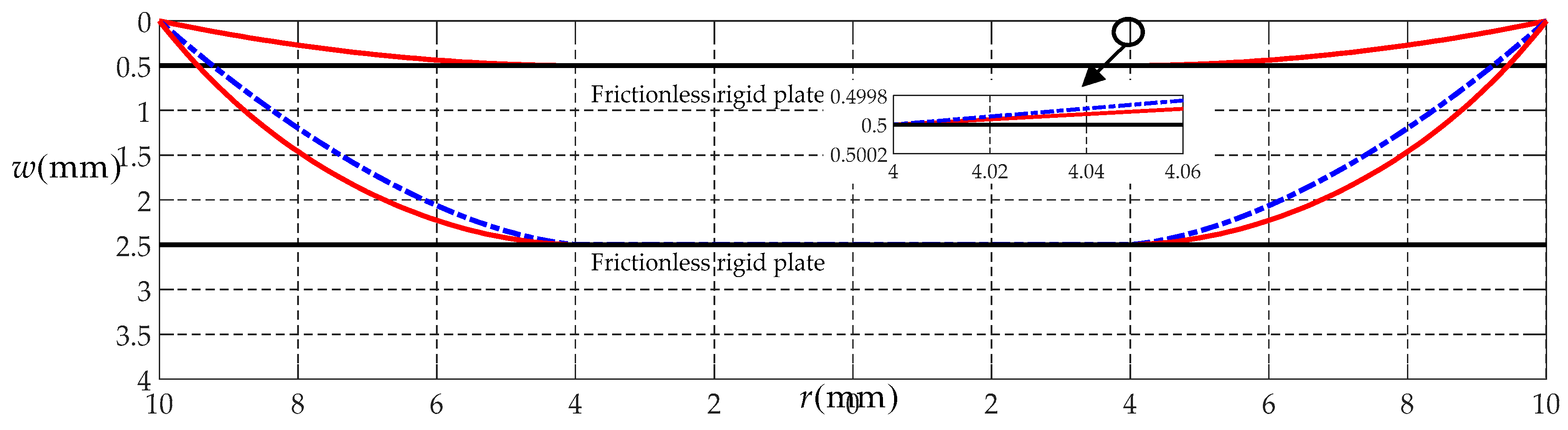
Now, let us address the difference between the solution presented in
Section 2, which applies to the gas pressure loading, and the solution presented in [
28], which applies to the gravity loading. Suppose that, the gap
g between the initially flat circular rubber membrane and the frictionless rigid plate takes 0.5 and 2.5 mm, respectively, and the contact radius
b between the deformed circular membrane and the frictionless rigid plate is always 4 mm whether the gap
g takes 0.5 or 2.5 mm. The calculated results by the solution presented in
Section 2 are
q = 0.001322 MPa for
g = 0.5 mm and
q = 0.1576 MPa for
g = 2.5 mm, respectively. While the calculated results by the solution presented in [
28] are
q = 0.001327 MPa for
g = 0.5 mm and
q = 0.1654 MPa for
g = 2.5 mm, respectively.
Figure 4 shows the variation of
w with
r, while
Figure 5 shows the variation of
with
r, in which the solid line represents the results calculated by the solution presented in
Section 2, and the dash-dotted line by the solution presented in [
28]. From
Figure 4, it may be seen that when
g = 0.5 mm and
b = 4 mm, the two deflection curves are very close to each other, while when
g = 2.5 mm and
b = 4 mm, there is clear difference in the shape of the two deflection curves. This difference is resulted from the improvement of the in-plane equilibrium equation. In this study, we employed the in-plane equilibrium equation presented in [
25] (i.e., Equation (4)), which applies to the gas pressure loading, while the in-plane equilibrium equation employed in [
28] applies to the gravity loading. In
Figure 5, the radial stress
, which is calculated by the solutions presented here (the solid lines) and presented in [
28] (the dash-dotted lines), respectively, is about 0.0382 and 0.0377 MPa at
r = 4 mm and 0.0336 and 0.0338 MPa at
r = 10 mm when
g = 0.5 mm, and is about 1.0658 and 0.9433 MPa at
r = 4 mm and 0.6262 and 0.8466 MPa at
r = 10 mm when
g = 2.5 mm. The maximum relative error is about 35%, while the allowable error for the precision measurement, instrument design, and the civil engineering is usually less than 1%, 3%, and 15%, respectively.
From
Figure 4 and
Figure 5, we may see that, when the gap
g is relatively small, the difference in deflection and stress of the two different solutions, which apply to the gas pressure loading and gravity loading, is very small and could be negligible, while when the gap
g is relatively large, the difference in deflection and stress of the two solutions must be taken seriously. This difference reminds us that the solution should be chosen to use according to the actual loading pattern, otherwise, the inappropriate use of solutions could result in too much loss of computational accuracy.
4. Concluding Remarks
In this study, the static problem of equilibrium of frictionless contact between an axisymmetric deflected circular membrane and a rigid plate was dealt with analytically, and the closed-form solution of the problem, which applies to the gas pressure loading, was presented. The following main conclusions can be drawn.
The mechanical behavior of the deformed circular membrane under gas pressure loading is different from that under gravity loading, so there is an essential difference between the solution obtained under gas pressure loading and the one obtained under gravity loading.
The solution obtained under gravity loading is still applicable to the gas pressurized circular membrane with a relatively small deflection, but will gradually lose its effectiveness along with the increase of the deflection of membranes.
The solution presented in this study was obtained under gas pressure loading, and therefore it is more suitable for the gas pressurized circular membrane with a relatively large deflection in comparison with the solution presented in [
28], which was obtained under gravity loading.
The closed-form solution presented in this study can be used to analyze or interpret the constrained pressurized blister tests, such as to study the effect of the attractive forces between the blistering thin film and the rigid surface on the radius of the circular contact area, or the relationship between the applied gas pressure, adhesion forces, and the contact radius.
In fact, the gravity loading usually refers to the external action resulted from the self-weight of structural members and is always downward, so it is usually difficult for us to apply the gravity loads onto the surface of a membrane, especially to change the loading level of the uniform lateral loading. However, it is relatively simple for us to apply the gas pressure onto the surface of a membrane. Therefore, the gas pressure loading is used in almost all the pressurized blister tests. In this sense, the closed-form solution for gas pressure loading presented in this study has a positive significance for promoting the related studies.


