Article

The Exact Solution of the Falling Body Problem in Three-Dimensions: Comparative Study

1
Department of Mathematics, Faculty of Science, University of Tabuk, Tabuk 71491, Saudi Arabia
2
Department of Mathematics, Faculty of Sciences and Humanities in Al-Kharj, Prince Sattam bin, Abdulaziz University, Al-Kharj 11942, Saudi Arabia
3
Department of Basic Engineering Science, Faculty of Engineering, Menofia University, Shebin El-Kom 32511, Egypt
*
Authors to whom correspondence should be addressed.
Mathematics 2020, 8(10), 1726; https://doi.org/10.3390/math8101726
Submission received: 17 August 2020 / Revised: 16 September 2020 / Accepted: 24 September 2020 / Published: 8 October 2020
(This article belongs to the Section Engineering Mathematics)

Abstract

:
Very recently, the system of differential equations governing the three-dimensional falling body problem (TDFBP) has been approximately solved. The previously obtained approximate solution was based on the fact that the Earth’s rotation (ER) is quite slow and hence all high order terms of ω in addition to the magnitude ω 2 R were neglected, where ω is the angular velocity and R is the radius of Earth. However, it is shown in this paper that the ignorance of such magnitudes leads, in many cases, to significant errors in the estimated falling time and other physical quantities. The current results are based on obtaining the exact solutions of the full TDFBP-system and performing several comparisons with the approximate ones in the relevant literature. The obtained results are of great interest and importance, especially for other planets in the Solar System or exterior planets, in which ω and/or ω 2 R are of considerable amounts and hence cannot be ignored. Therefore, the present analysis is valid in analyzing the TDFBP near to the surface of any spherical celestial body.

1. Introduction

In the past decades, some attention was given to the study of the falling body problem [1,2,3] and two-dimensional projectile motion [4,5,6,7,8,9,10,11,12,13,14]. In the literature [1,2,3], the falling body problem was modeled as the vertical motion of a particle near the Earth’s gravitational field, i.e., as a problem formulated in one dimension. Hence, the results obtained in [1,2,3] and in [4,5,6,7,8,9,10,11,12,13,14] were only valid in a fixed frame, that is, a non-rotating one. By this, the effect of Earth’s rotation (ER) on the falling body problem and also on the projectile motion was not considered. In addition, the effect of ER on the three dimensional-falling body problem (TDFBP) was analyzed very recently by El-Zahar et al. [15]. However, the analysis introduced by El-Zahar et al. [15] still has some restrictions where all high order terms of ω in addition to the magnitude ω 2 R were neglected. In this paper, we consider the effect of the ER on the TDFBP without any constraints/restrictions where all of the physical quantities are left arbitrary and therefore the present results generalize the previously published ones in [15]. The physical problem is described as follows. Let r = ( x ( t ) , y ( t ) , z ( t ) ) be the position vector of a particle located at a point Q near the Earth’s surface, relative to P (a surface point) as in Figure 1.
The equations of motion in the frame ( x , y , z ) are given by [15,16,17]:
x ¨ ( t ) = ( 2 ω cos λ ) y ˙ ( t ) + ω 2 ( x ( t ) cos λ + ( R + z ( t ) ) sin λ ) cos λ ,
y ¨ ( t ) = ( 2 ω cos λ ) x ˙ ( t ) ( 2 ω sin λ ) z ˙ ( t ) + ω 2 y ( t ) ,
z ¨ ( t ) = g + ( 2 ω sin λ ) y ˙ ( t ) + ω 2 ( x ( t ) cos λ + ( R + z ( t ) ) sin λ ) sin λ ,
where g represents the acceleration due to gravity, ω denotes the Earth’s angular velocity, λ [ 0 , π ] is the colatitude, and R is the Earth’s radius. Moreover, the x , y , and z directions points south, east, and up, respectively. Moreover, assume that a particle is released from rest at the point Q = ( x 0 , y 0 , z 0 ) ; hence, the initial conditions (ICs) are:
x ( 0 ) = x 0 , y ( 0 ) = y 0 , z ( 0 ) = z 0 ,
x ˙ ( 0 ) = 0 , y ˙ ( 0 ) = 0 , z ˙ ( 0 ) = 0 .
In the literature [15], system (1)–(4) has been approximately solved by neglecting all high order terms of ω in addition to the magnitude ω 2 R . The present problem may be of practical importance in engineering and space sciences as explained below. Every day, many planes, satellites, and other space objects (such as the Mir Space Station and the International Space Station) orbit the Earth at different altitudes from the surface of the Earth. The Earth’s planet is also exposed, annually, to many crashes of some aircrafts and meteorites, which cause a potential danger to vital installations and regions of population density in some countries. Therefore, the accurate identification of the possible location of these falling objects clearly helps in the possibility of finding them successfully; hence, the importance of the current study. So, the objective of this paper is to solve the present system, taking into account the contributions of all terms without any constraints/restrictions on any of the physical quantities.

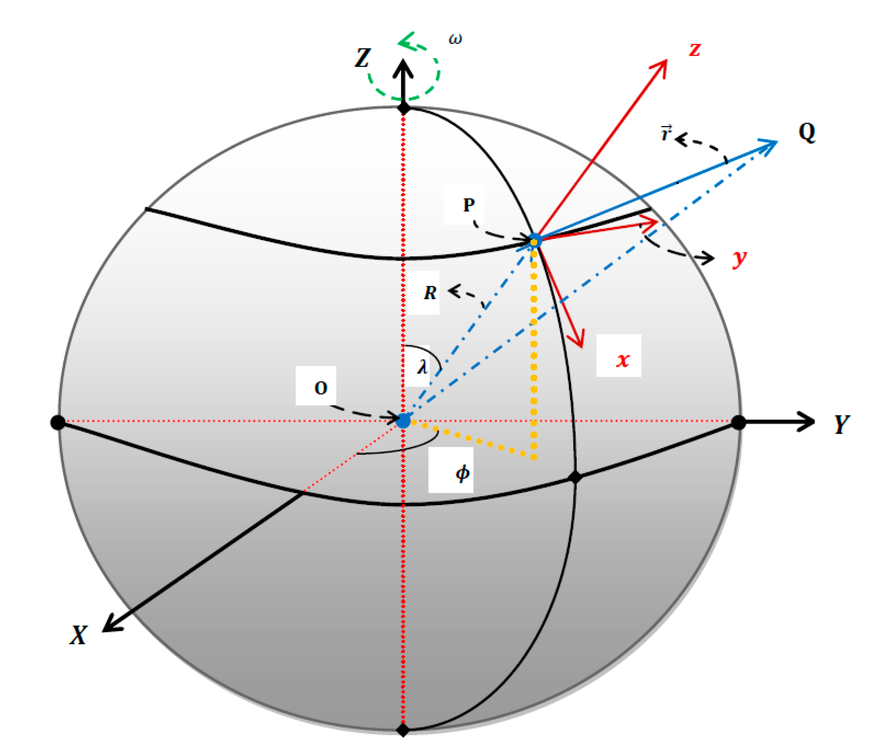
2. The Exact Solution

In this section, the exact solution of the full system (1)–(4) will be obtained without neglecting any of the higher orders of ω and also the magnitude ω 2 R . The present approach implements the Laplace transform (LT) to exactly solving the full model (1)–(4). The Laplace transform and its properties are listed in Appendix A. Applying the LT on system (1)–(4) and in view of Equations (A4)–(A6), we have:
( s 2 B ) X ( s ) C Z ( s ) A s Y ( s ) + ( A y 0 x 0 s C R s ) = 0 ,
( s 2 ω 2 ) Y ( s ) + A s X ( s ) + D s Z ( s ) ( A x 0 + y 0 s + D z 0 ) = 0 ,
( s 2 E ) Z ( s ) C X ( s ) D s Y ( s ) + ( g E R s z 0 s + D y 0 ) = 0 ,
where:
A = 2 ω cos λ , B = ω 2 cos 2 λ , C = ω 2 sin λ cos λ ,
D = 2 ω sin λ , E = ω 2 sin 2 λ ,
and X ( s ) , Y ( s ) , and Z ( s ) are the LT of x ( t ) , y ( t ) , and z ( t ) , respectively. Solving system (6)–(8) for X ( s ) , Y ( s ) , and Z ( s ) , and implementing (9)–(10), we obtain:
X ( s ) = 2 x 0 s 6 + ( ω 2 k 1 ) s 4 + ( 4 ω 3 y 0 cos λ ) s 3 + ω 2 ( ω 2 k 2 + 3 g sin 2 λ ) s 2 + ( ω 4 g sin 2 λ ) 2 s 3 ( s 2 + ω 2 ) 2 ,
Y ( s ) = y 0 s 3 + ( 3 ω 2 y 0 ) s + ω k 3 ( s 2 + ω 2 ) 2 ,
Z ( s ) = z 0 s 6 + k 4 s 4 + ( 2 ω 3 y 0 sin λ ) s 3 + ( ω 2 k 5 ) s 2 ( ω 4 g cos 2 λ ) s 3 ( s 2 + ω 2 ) 2 ,
where:
k 1 = ( R + z 0 ) sin 2 λ + ( 5 + cos 2 λ ) x 0 ,
k 2 = ω 2 ( 6 x 0 k 1 ) ,
k 3 = 2 ω 2 x 0 cos λ 2 ( g + ω 2 ( z 0 + R ) ) sin λ ,
k 4 = g + ω 2 ( R sin 2 λ + 1 2 x 0 sin 2 λ + 1 2 z 0 ( 5 cos 2 λ ) ) ,
k 5 = 3 ω 2 z 0 3 g cos 2 λ k 4 .
Applying the inverse LT on (11)–(13), we obtain the explicit forms of x ( t ) , y ( t ) , and z ( t ) as:
x ( t ) = 1 4 ω 2 [ 2 ω 2 k 2 + g ( 2 + ω 2 t 2 ) sin 2 λ ] + 1 4 ω [ 4 ω y 0 cos λ + ( ω 2 ( k 1 k 2 2 x 0 ) 2 g sin 2 λ ) t ] × sin ω t 1 2 ω 2 [ ω 2 ( k 2 2 x 0 ) + g sin 2 λ + ( 2 ω 3 y 0 cos λ ) t ] cos ω t ,
y ( t ) = ( y 0 k 3 t 2 ω ) cos ω t + ( ω y 0 t + k 3 2 ω 2 ) sin ω t ,
z ( t ) = 1 4 ω 2 [ 4 k 5 + 2 g ( 4 ω 2 t 2 ) cos 2 λ ] 1 ω 2 [ k 5 + 2 g cos 2 λ ω 2 z 0 + ( ω 3 y 0 sin λ ) t ] cos ω t 1 4 ω [ 4 ω y 0 sin λ + 2 ( k 5 k 4 + ω 2 z 0 + g cos 2 λ ) t ] sin ω t .
Equations (19)–(21) express the solution of the TDFBP model (1)–(4) without any assumptions or restrictions on ω and ω 2 R . Expanding x ( t ) , y ( t ) , and z ( t ) in (19)–(21) as power series in ω , yields:
x ( t ) = x 0 + t 2 8 cos λ ( 4 x 0 cos λ + ( g t 2 + 4 z 0 + 4 R ) sin λ ) ω 2 + ( t 3 3 y 0 cos λ ) ω 3 + ,
y ( t ) = y 0 + ( g t 3 3 sin λ ) ω + ( y 0 t 2 2 ) ω 2 t 3 30 ( 10 x 0 cos λ + ( g t 2 + 10 z 0 + 10 R ) sin λ ) ω 3 + ,
z ( t ) = ( z 0 g t 2 2 ) + t 2 8 sin λ ( 4 x 0 cos λ + ( g t 2 + 4 z 0 + 4 R ) sin λ ) ω 2 + ( y 0 t 3 3 sin λ ) ω 3 + .
As ω 2 0 , the results (22)–(24) reduce to:
x ( t ) = x 0 , y ( t ) = y 0 + ( g t 3 3 sin λ ) ω , z ( t ) = z 0 g t 2 2 ,
which are the corresponding results obtained in [15] when higher powers of ω , i.e., ω n     n 2 , are neglected. Furthermore, as ω 2 0 , the horizontal and vertical displacements x ( t ) and z ( t ) , respectively, are independent of the angular velocity ω . Moreover, Equations (22)–(24) reduce to some useful results at several special cases as declared in the subsequent sections.

3. Coordinates and Characteristics of the Falling Point

3.1. Coordinates of the Falling Point

Let G be the point at which the falling body hits the x y -plane, see Figure 2. At such point, the vertical displacement z ( t ) vanishes. Suppose that T is the time required such that z ( T ) = 0 ; then, the Cartesian coordinates of the falling point G in the local frame ( x , y , z ) can be expressed as ( x G , y G , z G ) = ( x ( T ) , y ( T ) , 0 ) . In addition, the Polar coordinates ( ρ , δ ) of G are:
ρ = ( x ( T ) ) 2 + ( y ( T ) ) 2 , δ = tan 1 ( y ( T ) x ( T ) ) .
In Appendix C, the coordinates of the falling point at various special cases are introduced.

3.2. Characteristics of the Falling Point

In this section, we highlight some of the characteristics of the particle’s falling point G. In particular, G lies on the Earth’s surface when some conditions are satisfied. As ρ 0 , G belongs to the Earth’s surface, as shown from Figure 2. However, ρ 0 implies xG = yG = 0. The following lemmas address these issues.
Lemma 1. 
If the particle is released from a point ( 0 , 0 , z 0 ) in the system ( x , y , z ) such that λ { 0 , π } , then G belongs to the Earth’s surface.
Proof of Lemma 1. 
Substituting x 0 = 0 and y 0 = 0 into (19)–(21) and implementing the corresponding k i ( i = 1,2,3,4,5) in (14)–(18), we have:
x ( t ) = sin 2 λ 4 ω 2 [ 2 ( g ω 4 ( z 0 + R ) ) ( 1 cos ω t ) + ω ( 2 g + ω 2 ( 1 + ω 2 ) ( z 0 + R ) ) t   sin ω t + ω 2 g t 2 ] ,
y ( t ) = sin λ ω 2 ( g ω 4 ( z 0 + R ) ) ( sin ω t ω t cos ω t ) ,
z ( t ) = 1 2 ω 2 [ g ω 2 ( R z 0 ) ω 2 g t 2 cos 2 λ ( g ω 2 ( z 0 + R ) ) ( cos 2 λ + 2 sin 2 λ × ( cos ω t + ω t sin ω t ) ) ] .
At such point G, the component z ( t ) vanishes at a particular value t = T . Hence, x G and y G are, respectively, given from (27) and (28) by
x G = sin 2 λ 4 ω 2 [ 2 ( g ω 4 ( z 0 + R ) ) ( 1 cos ω T ) + ω ( 2 g + ω 2 ( 1 + ω 2 ) ( z 0 + R ) ) T sin ω T + ω 2 g T 2 ] ,
y G = sin λ ω 2 ( g ω 4 ( z 0 + R ) ) ( sin ω T ω T cos ω T ) ,
where T is a non-trivial solution of the following equation ( z ( T ) = 0 ):
g ω 2 ( R z 0 ) ω 2 g T 2 cos 2 λ ( g ω 2 ( z 0 + R ) ) ( cos 2 λ + 2 sin 2 λ ( cos ω T + ω T sin ω T ) ) .
It is clear from Equations (30) and (31) that x G = y G = 0 when sin 2 λ = 0 and sin λ = 0 . These two equations imply that λ { 0 , π } which completes the proof. In addition, Equation (29) reduces to:
2 z 0 g T 2 = 0 which   gives T = 2 z 0 g .
As a confirmation of this Lemma, we have from Appendix C (1 and 2) that ρ = ( 1 + ω 2 T 2 ) ( x 0 2 + y 0 2 ) for λ = 0 or π . When ( x 0 , y 0 ) ( 0 , 0 ) , we observe that ρ 0 ; hence, G lies on the Earth’s surface. □
Lemma 2. 
If x 0 = 0 and y 0 = 0 , then the falling point G is equivalent to the North Pole and the South Pole of Earth when λ = 0 and λ = π , respectively.
Proof of Lemma 2. 
Let us first introduce the relation between the systems ( x , y , z ) and ( X , Y , Z ) described in Figure 1. It was shown in [16,17] that the following transformations hold after a time t :
X ( t ) = x ( t ) cos λ cos ω t y ( t ) sin ω t + ( R + z ( t ) ) sin λ cos ω t ,
Y ( t ) = x ( t ) cos λ sin ω t + y ( t ) cos ω t + ( R + z ( t ) ) sin λ sin ω t ,
Z ( t ) = x ( t ) sin λ + ( R + z ( t ) ) cos λ .
From Lemma 1, it was proved that T = 2 z 0 g when x 0 = y 0 = 0 and λ { 0 , π } , where G = ( x G , y G , z G ) = (0,0,0) in the local frame ( x , y , z ) . Accordingly, the Cartesian coordinates ( X G , Y G , Z G ) of G in the inertial frame ( X , Y , Z ) are:
X G = x G cos λ cos ( ω 2 z 0 g ) y G sin ( ω 2 z 0 g ) + ( R + z G ) sin λ cos ( ω 2 z 0 g ) ,
Y G = x G cos λ sin ( ω 2 z 0 g ) + y G cos = ( ω 2 z 0 g ) + ( R + z G ) sin λ sin ( ω 2 z 0 g ) ,
Z G = x G sin λ + ( R + z G ) cos λ .
Substituting x G = y G = z G = 0 into Equations (37)–(39) yields:
X G = R sin λ cos ( ω 2 z 0 g ) ,
Y G = R sin λ sin ( ω 2 z 0 g ) ,
Z G = R cos λ .
At λ = 0 , we obtain:
X G = 0 , Y G = 0 , Z G = R ,
which are the Cartesian coordinates of the North pole in the frame ( X , Y , Z ) . Moreover, we have from Equations (40)–(42) at λ = π that:
X G = 0 , Y G = 0 , Z G = R ,
which are equivalent to the Cartesian coordinates of the South Pole. □

4. Results and Discussions

This section presents the main difference between the current exact results and those approximately obtained by El-Zahar et al. [15]. Besides, the two Lemmas presented in the previous section will be numerically and graphically validated in this discussion. First of all, the falling time T is approximately obtained in [15] by T Approx .   =   2 z 0 g   λ [ 0 , π ] . At λ = 0 , π , it is noted from Appendix C (1 and 2) that the falling time T is obtained by T = 2 z 0 g which agrees with the corresponding expression in [15]. In such special cases, there is no difference between the current exact formula of the falling time T and the corresponding approximate one in [15]. However, when λ takes other values, i.e., λ ( 0 , π ) , there are differences in the calculations of T . In these cases, the exact values of T ( T Exact ) can be calculated by solving Equation (21) as z ( T Exact ) = 0 ; hence, the error formula of T is defined as:
Error ( T ) = T Exact 2 z 0 g .
Table 1 presents the comparisons between the current values of the falling time T and the corresponding results in [15] at twenty different cases of the colatitude λ and the release point Q. The results reveal that the obtained error increases as the colatitude λ increases, especially at the equator of the Earth ( λ = π / 2 ). In [15], the approximate Cartesian coordinates ( x G ) Approx . and ( y G ) Approx . of the falling point G were given by:
( x G ) Approx . = x 0 , ( y G ) Approx . = y 0 + ( ω g 3 ) ( 2 z 0 g ) 3 sin λ ,
and the approximate polar coordinates ( ρ ) Approx . and ( δ ) Approx . of G were obtained as [15]:
( ρ ) Approx . = x 0 2 + ( y 0 + ( ω g 3 ) ( 2 z 0 g ) 3 sin λ ) 2 ,
( δ ) Approx . = tan 1 ( ( 3 y 0 + ω g ( 2 z 0 g ) 3 sin λ ) / 3 x 0 ) .
Therefore, the errors in x G , y G , ρ , and δ at λ = 0 are given by:
Error ( x G ) = ( x 0 ω y 0 2 z 0 g ) cos ( ω 2 z 0 g ) + ( y 0 + ω x 0 2 z 0 g ) sin ( ω 2 z 0 g ) x 0 ,
Error ( y G ) = ( y 0 + ω x 0 2 z 0 g ) cos ( ω 2 z 0 g ) ( x 0 ω y 0 2 z 0 g ) sin ( ω 2 z 0 g ) y 0 ,
Error ( ρ ) = ( 1 + ω 2 T 2 ) ( x 0 2 + y 0 2 ) x 0 2 + y 0 2 ,
Error ( δ ) = tan 1 ( ( y 0 + ω x 0 2 z 0 g ) cos ( ω 2 z 0 g ) ( x 0 ω y 0 2 z 0 g ) sin ( ω 2 z 0 g ) ( x 0 ω y 0 2 z 0 g ) cos ( ω 2 z 0 g ) + ( y 0 + ω x 0 2 z 0 g ) sin ( ω 2 z 0 g ) ) tan 1 ( y 0 x 0 ) .
Similarly, at λ = π , we have:
Error ( x G ) = ( x 0 + ω y 0 2 z 0 g ) cos ( ω 2 z 0 g ) ( y 0 ω x 0 2 z 0 g ) sin ( ω 2 z 0 g ) x 0 ,
Error ( y G ) = ( y 0 ω x 0 2 z 0 g ) cos ( ω 2 z 0 g ) + ( x 0 + ω y 0 2 z 0 g ) sin ( ω 2 z 0 g ) y 0 ,
Error ( ρ ) = ( 1 + ω 2 T 2 ) ( x 0 2 + y 0 2 ) x 0 2 + y 0 2 ,
Error ( δ ) = tan 1 ( ( y 0 ω x 0 2 z 0 g ) cos ( ω 2 z 0 g ) + ( x 0 + ω y 0 2 z 0 g ) sin ( ω 2 z 0 g ) ( x 0 + ω y 0 2 z 0 g ) cos ( ω 2 z 0 g ) ( y 0 ω x 0 2 z 0 g ) sin ( ω 2 z 0 g ) ) tan 1 ( y 0 x 0 ) .
Table 2 presents the obtained errors in the Cartesian coordinates of the falling point G ( x G , y G , 0 ) in the frame ( x , y , z ) and the corresponding errors in the Polar coordinates ( ρ , δ ) at several points Q ( x 0 , y 0 , z 0 ) when λ = 0 , π . The results of Table 2 indicate that the obtained errors in ρ and δ are of the amount at λ = 0 (North Pole) and λ = π (South Pole). In addition, the errors increase as the height z 0 increases above the Earth’s surface. While the obtained errors in ρ and δ in Table 2 seem very small at these particular values of the colatitude λ , it will be declared that the errors in x G and y G , ρ , and δ are significant at other values of λ ( 0 , π ) . Repeating the analysis above at λ = π / 6 , λ = π / 4 , λ = π / 3 , and λ = π / 2 , we calculated the errors of x G and y G , as introduced in Table 3.
The results show that the errors in x G and y G increases as λ , x 0 , y 0 , and z 0 increase. For example, when the release point Q ( x 0 , y 0 , z 0 ) takes the values Q(10,10,10), the errors in x G are found as 14.9922 m at λ = π / 6 , 17.3067 m at λ = π / 4 , 75.9343 m at λ = π / 3 . However, the obtained maximum errors in y G are 1.4469 m when λ = π / 3 . Moreover, at λ = π / 2 (the equator of Earth), the obtained errors in x G are small for the five cases of Q ( x 0 , y 0 , z 0 ) , while the obtained error in y G becomes significant and considerable, equaling 246.6514 m for Q(50,50,50). Of course, the significant errors in the Cartesian coordinates x G and in y G imply significant errors in the polar coordinates ρ and in δ . The above calculations implemented the real data of the Earth’s planet and can also be extended to cover other planets in the Solar System. Finally, the advantage of the present analysis over the previously published one is observable, especially when applied to specific planets of greater radius R and greater angular velocity ω than those of the Earth.
In order to confirm such conclusion, the current exact solutions are applied for all planets in our Solar System, Mercury, Venus, Earth, Mars, Jupiter, Saturn, Uranus, and Neptune. Astronomers usually divide the planets into two groups, which are known as the inner planets (Mercury, Venus, Earth, and Mars) and the outer planets (Jupiter, Saturn, Uranus, and Neptune) [18]. It will be indicated below that the obtained errors for the falling time T and the landing positions ( x G , y G , 0) are bigger for the outer planets than those of the inner planets.
In Table 4, the physical data for all planets are introduced. Before launching to the main results, it can be seen from Table 4 that the value of angular velocity ω of any outer planet (Jupiter, Saturn, Uranus, and Neptune) is greater than the value of any inner planet. This means that the outer planets rotate more speedily about their axes than the inner planets. In another word, the Coriolis effect is expected to affect the calculated errors for outer planets more than it does for the inner planets. In addition, the radii of the outer planets are greater than the radii of the inner planets. So, it is expected that the differences between the present exact solutions and the approximate ones [15] will greatly appear in the cases of outer planets.
Our point of view can be confirmed through the calculations in Table 5 and Table 6 for λ = π / 6 and λ = π / 4 , respectively. Such calculations are based on assuming that a projectile, at rest, is released from the point Q(50,50,50). The results in Table 5 and Table 6 reveal that the obtained errors of T for outer planets are greater than those of inner ones. In addition, for the obtained errors of y G , although small for all planets, we find that the corresponding errors of x G are significant, especially, for those outer planets. Therefore, the current exact analysis may be more helpful than the approximate one, particularly when studying the falling body problem near to the surface of a planet with greater values of ω and R than those of Earth, as it already appeared in cases of Jupiter, Saturn, Uranus, and Neptune. Finally, we are in a period of new planets, new space bodies. For this reason, the current results may also be valid for new planets, which may be discovered later.

5. Conclusions

In this paper, the three dimensional model of the falling body problem near the Earth’s surface was analyzed, taking into account the contribution of all physical quantities. Moreover, unlike the previous published paper [15], the values of the involved parameters were left arbitrary without any restrictions/constraints. Thus, the exact solutions of the full-three coupled equations of motion were obtained in terms of the release point Q ( x 0 , y 0 , z 0 ) , the colatitude λ , the angular velocity ω , and the radius R of Earth. The present analysis was based on the Laplace transform as a method of solution. Furthermore, the properties of the falling point in the rotating frame and the original inertial frame were given by means of two lemmas. In addition, the conditions at which the falling point belongs G = ( x G , y G , z G ) to the Earth’s surface were theoretically proven. The effectiveness and validity of the present analysis over the published one in the literature [15] arises when applied to other planets of greater radius R and angular velocity ω than those of the Earth. Hence, the present analysis is applicable to analyzing the TDFBP near enough to the surface of any spherical celestial body.

Author Contributions

Conceptualization, A.E. and E.R.E.-Z.; methodology, A.E., W.A., and E.R.E.-Z.; software, E.R.E.-Z., M.D.A. and A.E.; validation, A.E., W.A., M.D.A., and E.R.E.-Z.; formal analysis, E.R.E.-Z., A.E. and M.D.A.; investigation, A.E., W.A., M.A., and E.R.E.-Z.; resources, M.D.A.; data curation, M.D.A.; writing—original draft preparation, W.A., E.R.E.-Z. and A.E.; writing—review and editing, A.E., W.A., M.D.A., and E.R.E.-Z. All authors have read and agreed to the published version of the manuscript.

Funding

This research received no external funding.

Acknowledgments

The authors would like to thank the referees for their valuable comments and suggestions which helped to improve the manuscript.

Conflicts of Interest

The authors declare no conflict of interest.

Appendix A

Laplace Transform and Its Properties

The LT of a function u ( t ) is defined as [19]
L { u ( t ) } = 0 e s t u ( t ) d t = U ( s ) ,
where the LT of u ( t ) is said to exist if the integral (A1) converges. The sufficient conditions for existence of the LT are detailed in [8], see pages (1–2). Moreover, the LT of the n -derivative of u ( t ) is given by [19].
L { u ( n ) ( t ) } = s n U ( s ) m = 0 n 1 s n m 1 u ( m ) ( 0 ) .
For n = 2 , we have
L { u ¨ ( t ) } = s n U ( s ) s u ( 0 ) u ˙ ( 0 ) .
Applying the last formula on x ¨ ( t ) , y ¨ ( t ) , and z ¨ ( t ) , yields
L ( x ¨ ( t ) ) = s 2 X ( s ) s x ( 0 ) x ˙ ( 0 ) ,
L ( y ¨ ( t ) ) = s 2 Y ( s ) s y ( 0 ) y ˙ ( 0 ) ,
L ( z ¨ ( t ) ) = s 2 Z ( s ) s z ( 0 ) z ˙ ( 0 ) ,

Appendix B

Appendix B.1. Special Cases

Appendix B.1.1. λ = 0 (North Pole)

At λ = 0 , we have from (14)–(18) the following values for k i , i = 1,2,3,4,5:
k 1 = 6 x 0 , k 2 = 0 , k 3 = 2 ω 2 x 0 , k 4 = g + 2 ω 2 z 0 , k 5 = 2 g + ω 2 z 0 .
Substituting (26) into (22)–(24), we obtain
x ( t ) = ( x 0 ω y 0 t ) cos ω t + ( y 0 + ω x 0 t ) sin ω t ,
y ( t ) = ( y 0 + ω x 0 t ) cos ω t ( x 0 ω y 0 t ) sin ω t ,
z ( t ) = z 0 g t 2 2 .
It is noted from these equations that only z ( t ) is independent of the angular velocity ω .

Appendix B.1.2. λ = π (South Pole)

In this case, we have
k 1 = 6 x 0 , k 2 = 0 , k 3 = 2 ω 2 x 0 , k 4 = g + 2 ω 2 z 0 , k 5 = 2 g + ω 2 z 0 .
Accordingly, Equations (22)–(24) become
x ( t ) = ( x 0 + ω y 0 t ) cos ω t ( y 0 ω x 0 t ) sin ω t ,
y ( t ) = ( y 0 ω x 0 t ) cos ω t + ( x 0 + ω y 0 t ) sin ω t ,
z ( t ) = z 0 g t 2 2 .
Equation (A14) indicates that z ( t ) is not influenced by ω as in the previous special case.

Appendix B.1.3. λ = π 2 (Equator)

At λ = π 2 and proceeding as above, we have
k 1 = 4 x 0 , k 2 = 2 ω 2 x 0 , k 3 = 2 g 2 ω 2 ( z 0 + R ) ,
k 4 = g + ω 2 ( 3 z 0 + R ) , k 5 = g ω 2 R ,
and
x ( t ) = ω 2 x 0 + ( 1 ω 2 ) x 0 cos ω t + 1 2 ω ( 1 ω 2 ) x 0 t sin ω t ,
y ( t ) = 1 ω [ ω y 0 ( g ω 2 ( z 0 + R ) ) t ] cos ω t + 1 ω 2 [ ω 3 y 0 t + ( g ω 2 ( z 0 + R ) ) ] sin ω t ,
z ( t ) = g ω 2 R ω 2 + 1 ω 2 [ g + ω 2 ( z 0 + R ) ω 3 y 0 t ] cos ω t + 1 ω [ ω y 0 + ( g + ω 2 ( z 0 + R ) ) t ] sin ω t .
Here, it can be seen from Equations (A17)–(A19) that ω is involved in all the components x ( t ) , y ( t ) , and z ( t ) .

Appendix C

Appendix C.1. Coordinates of the Falling Point at Special Cases

Appendix C.1.1. λ = 0 (North Pole)

From (A10), by solving the equation z ( T ) = 0 for T , we obtain
T = 2 z 0 g .
Hence, x G and y G are given from (B.2,3) by
x G = ( x 0 ω y 0 T ) cos ω T + ( y 0 + ω x 0 T ) sin ω T ,
y G = ( y 0 + ω x 0 T ) cos ω T ( x 0 ω y 0 T ) sin ω T .
From Equatios (26), we have
ρ = ( 1 + ω 2 T 2 ) ( x 0 2 + y 0 2 ) ,
δ = tan 1 ( ( y 0 + ω x 0 T ) cos ω T ( x 0 ω y 0 T ) sin ω T ( x 0 ω y 0 T ) cos ω T + ( y 0 + ω x 0 T ) sin ω T ) , x 0 0 , y 0 0 .

Appendix C.1.2. λ = π (South Pole)

In this case, we have
x G = ( x 0 + ω y 0 T ) cos ω T ( y 0 ω x 0 T ) sin ω T ,
y G = ( y 0 ω x 0 T ) cos ω T + ( x 0 + ω y 0 T ) sin ω T ,
where T is defined by (C.1) and consequently
ρ = ( 1 + ω 2 T 2 ) ( x 0 2 + y 0 2 ) ,
δ = tan 1 ( ( y 0 ω x 0 T ) cos ω T + ( x 0 + ω y 0 T ) sin ω T ( x 0 + ω y 0 T ) cos ω T ( y 0 ω x 0 T ) sin ω T ) , x 0 0 , y 0 0 .

Appendix C.1.3. λ = π 2 (Equator)

In the previous cases, the time T was explicitly obtained as seen from (C.1). However, the present case is different and requires solving the following implicit equation in T:
g ω 2 R ω 2 + 1 ω 2 [ g + ω 2 ( z 0 + R ) ω 3 y 0 T ] cos ω T + 1 ω [ ω y 0 + ( g + ω 2 ( z 0 + R ) ) T ] sin ω T = 0 ,
which can be simplified as
( g ω 2 R ) + [ g + ω 2 ( z 0 + R ) ω 3 y 0 T ] cos ω T + ω [ ω y 0 + ( g + ω 2 ( z 0 + R ) ) T ] sin ω T = 0 .
The corresponding x G and y G are given as and
x G = ω 2 x 0 + ( 1 ω 2 ) x 0 cos ω T + 1 2 ω ( 1 ω 2 ) x 0 T sin ω T ,
y G = 1 ω [ ω y 0 ( g ω 2 ( z 0 + R ) ) T ] cos ω T + 1 ω 2 [ ω 3 y 0 T + ( g ω 2 ( z 0 + R ) ) ] sin ω T .
Hence
ρ = x G 2 + y G 2 ,
δ = tan 1 ( ω [ ω y 0 ( g ω 2 ( z 0 + R ) ) T ] cos ω T + [ ω 3 y 0 T + ( g ω 2 ( z 0 + R ) ) ] sin ω T ω 4 x 0 + ω 2 ( 1 ω 2 ) x 0 cos ω T + 1 2 ω 3 ( 1 ω 2 ) x 0 T sin ω T ) ,
where x 0 .

References

  1. Kwok, S.F. A falling body problem through the air in view of the fractional derivative approach. Phys. A Stat. Mech. Appl. 2005, 350, 199–206. [Google Scholar]
  2. Garcia, J.J.R.; Calderon, M.G.; Ortiz, J.M.; Baleanu, D.; de Santiago, C.S.V. Motion of a particle in a resisting medium using fractional calculus approach. Proc. Rom. Acad. A 2013, 14, 42–47. [Google Scholar]
  3. Ebaid, A.; Masaedeh, B.; Machado, J.A.T. A New Fractional Model for the Falling Body Problem. Chin. Phys. Lett. 2017, 34, 20201. [Google Scholar] [CrossRef]
  4. Hayen, J.C. Projectile motion in a resistant medium: Part I: Exact solution and properties. Int. J. Non-linear Mech. 2003, 38, 357–369. [Google Scholar] [CrossRef]
  5. Hayen, J.C. Projectile motion in a resistant medium Part II: Approximate solution and estimates. Int. J. Non-linear Mech. 2003, 38, 371–380. [Google Scholar] [CrossRef]
  6. Weinacht, P.; Cooper, G.R.; Newell, J.F. Analytical Prediction of Trajectories for High-Velocity Direct-Fire Munitions; Technical report ARL-TR-3567; US Army Research Laboratory: Aberdeen Proving Ground, MD, USA, 2005. [Google Scholar]
  7. Yabushita, K.; Yamashita, M.; Tsuboi, K. An analytic solution of projectile motion with the quadratic resistance law using the homotopy analysis method. J. Phys. A Math. Theor. 2007, 40, 8403–8416. [Google Scholar] [CrossRef]
  8. Benacka, J. Solution to projectile motion with quadratic drag and graphing the trajectory in spreadsheets. Int. J. Math. Educ. Sci. Technol. 2010, 41, 373–378. [Google Scholar] [CrossRef]
  9. Benacka, J. On high-altitude projectile motion. Can. J. Phys. 2011, 89, 1003–1008. [Google Scholar] [CrossRef]
  10. Ebaid, A. Analysis of projectile motion in view of fractional calculus. Appl. Math. Model. 2011, 35, 1231–1239. [Google Scholar] [CrossRef]
  11. Rosales, J.J.; Guía, M.; Gómez, F.; Aguilar, F.; Martinez, J. Two dimensional fractional projectile motion in a resisting medium. Open Phys. 2014, 12, 517–520. [Google Scholar] [CrossRef]
  12. Ahmad, B.; Batarfi, H.; Nieto, J.J.; Otero-Zarraquiños, Ó.; Shammakh, W. Projectile motion via Riemann-Liouville calculus. Adv. Differ. Equ. 2015, 2015, 1231. [Google Scholar] [CrossRef] [Green Version]
  13. Alharbi, F.M.; Baleanu, D.; Ebaid, A. Physical properties of the projectile motion using the conformable derivative. Chin. J. Phys. 2019, 58, 18–28. [Google Scholar] [CrossRef]
  14. Ebaid, A.; El-Zahar, E.R.; Aljohani, A.; Salah, B.; Krid, M.; Machado, J.T. Analysis of the two-dimensional fractional projectile motion in view of the experimental data. Nonlinear Dyn. 2019, 97, 1711–1720. [Google Scholar] [CrossRef]
  15. Seddek, L.; Ebaid, A.; Aljohani, A.; Machado, J.A.T.; Baleanu, D. Re-Evaluating the Classical Falling Body Problem. Mathematics 2020, 8, 553. [Google Scholar] [CrossRef] [Green Version]
  16. Spiegel, M.R. Schaum’s Outline of Theory and Problems of Theoretical Mechanics; McGraw Hill: New York, NY, USA, 1967. [Google Scholar]
  17. Poisson, E. Advanced Mechanics; Lecture Notes; Department of Physics, University of Guelph: Guelph, ON, Canada, 2008. [Google Scholar]
  18. NASA Science. Solar System Exploration. Available online: https://solarsystem.nasa.gov/planets/overview/ (accessed on 27 September 2020).
  19. Spiegel, M.R. Laplac Transforms; McGraw Hill: New York, NY, USA, 1965. [Google Scholar]
Figure 1. An inertial frame (X,Y,Z) attached to the centre of the Earth, and a point P on the surface, described by colatitude λ and longitude ϕ . The local Cartesian frame (x,y,z) at P. The x direction points south, the y direction points east, and the z direction points up. The position vector of a point Q relative to P is denoted r .
Mathematics 08 01726 g001
Figure 2. The particle, at rest, released from Q in the local Cartesian frame ( x , y , z ) hits the xy- plane at a point G. The angle between PG and the x -axis is denoted δ .
Mathematics 08 01726 g002
Table 1. Comparisons between the present values of the falling time ( T ) (s) and the corresponding results in [15] at various values of the colatitude ( λ ) (radian) and the release point Q.
Case Colatitude   ( λ ) (Radian) Cartesian Coordinates of the Release Point Q Falling   Time   ( T ) (S)
x 0   ( km ) y 0   ( km ) z 0   ( km ) Exact (Present)Approximate [15]Error
1 π / 6 10101045.194945.17540.0195
2 π / 6 20202063.915463.88770.0277
3 π / 6 30303078.280378.24610.0342
4 π / 6 40404090.390590.35080.0397
5 π / 6 505050101.0598101.01530.0445
6 π / 4 10101045.214545.17540.0391
7 π / 4 20202063.943163.88770.0554
8 π / 4 30303078.314378.24610.0682
9 π / 4 40404090.429990.35080.0791
10 π / 4 505050101.1040101.01530.0887
11 π / 3 10101045.234045.17540.0586
12 π / 3 20202063.970863.88770.0831
13 π / 3 30303078.348378.24610.1022
14 π / 3 40404090.469290.35080.1184
15 π / 3 505050101.1480101.01530.1327
16 π / 2 10101045.253545.17540.0781
17 π / 2 20202063.998463.88770.1107
18 π / 2 30303078.382078.24610.1359
19 π / 2 40404090.508290.35080.1574
20 π / 2 505050101.1916101.01530.1763
Table 2. The obtained errors of the Cartesian coordinates of the falling point G ( x G , y G , 0 ) in the frame ( x , y , z ) and the corresponding errors in the polar coordinates ( ρ , δ ) at several points Q ( x 0 , y 0 , z 0 ) when λ = 0 , π .
Case Colatitude   ( λ ) (Radian) Cartesian Coordinates of the Release Point QError of Cartesian Coordinates of GError of Polar
Coordinates of G
x 0   ( km ) y 0   ( km ) z 0   ( km ) Error   of   x G   ( m ) Error   of   y G   ( m ) Error   of   ρ Error   of   δ ( × 10 8 ) ( Radian )
101010100.05410.05380.07631.1819
202020200.21650.21520.30533.3429
303030300.48750.48380.68686.1413
404040400.86720.85961.22119.4550
505050501.35571.34251.907913.2137
6 π 1010100.21520.05410.07631.1819
7 π 2020200.48380.21650.30533.3429
8 π 3030300.85960.48750.68686.1413
9 π 4040401.34250.86721.22119.4550
10 π 5050500.21521.35571.907913.2137
Table 3. The obtained errors of x G and y G at several release points Q ( x 0 , y 0 , z 0 ) when λ = π / 6 , π / 4 , π / 3 , π / 2 .
Case Colatitude   ( λ ) (Radian) Cartesian Coordinates of the Release Point QError of Cartesian
Coordinates of G
x 0   ( km ) y 0   ( km ) z 0   ( km ) Error   of   x G   ( m ) Error   of   y G   ( m )
1 π / 6 10101014.99220.0303
2 π / 6 20202030.13610.1487
3 π / 6 30303045.43170.3619
4 π / 6 40404060.87930.6722
5 π / 6 50505076.47891.0808
6 π / 4 10101017.30670.0407
7 π / 4 20202034.74890.1782
8 π / 4 30303052.32710.4166
9 π / 4 40404070.04120.7570
10 π / 4 50505087.89121.2004
11 π / 3 10101014.99110.0623
12 π / 3 20202030.07990.2398
13 π / 3 30303045.26670.5302
14 π / 3 40404060.55150.9327
15 π / 3 50505075.93431.4469
16 π / 2 1010104.8873 × 10−821.9937
17 π / 2 2020203.9099 × 10−762.2715
18 π / 2 3030301.3196 × 10−6114.4901
19 π / 2 4040403.1280 × 10−6176.3861
20 π / 2 5050506.1094 × 106246.6514
Table 4. Data for the planets in the Solar System [18].
PlanetRatio of Acceleration Due to Gravity [Earth = 1]Acceleration Due to Gravity [m/s2]Radius (km)Rotation Period (in Earth Days) Angular Velocity [s−1]
Mercury0.383.7278243958.651.24 × 10−6
Venus0.98.82960522432.99 × 10−7
Earth19.8063781.007.27 × 10−5
Mars0.383.727833941.037.10 × 10−5
Jupiter2.6425.898471,4000.411.80 × 10−4
Saturn0.939.123360,0000.441.70 × 10−4
Uranus0.898.730925,5590.721.0 × 10−4
Neptune1.1210.987224,7640.721.0 × 10−4
Table 5. The obtained errors of the falling time T , x G , and y G for all planets in the Solar System at the release point Q(50,50,50) (km) when λ = π / 6 .
PlanetErrors of Falling Time (T) [S] Errors   of   x G and   y G
Error   of   x G   ( m ) Error   of   y G   ( m )
Mercury0.0000220.023340.00103
Venus0.0000200.007140.00003
Earth0.04459376.481.08084
Mars0.098546104.252.80507
Jupiter0.7072711982.687.62458
Saturn2.5867104332.4129.9594
Uranus0.396289642.560.43672
Neptune0.271695493.980.01481
Table 6. The obtained errors of the falling time T , x G , and y G for all planets in the Solar System at the release point Q(50,50,50) (km) when λ = π / 4 .
PlanetErrors of Falling Time (T) [S] Errors   of   x G and   y G
Error   of   x G   ( m ) Error   of   y G   ( m )
Mercury0.000040.026370.00103
Venus0.000010.001530.00003
Earth0.0887487.89121.20038
Mars0.19522119.2683.06653
Jupiter1.438502341.83.25094
Saturn5.371705262.6116.1197
Uranus0.79587746.4240.99274
Neptune0.54491572.8140.99814

