Article

Numerical Simulation of Rotor–Wing Transient Interaction for a Tiltrotor in the Transition Mode

1
School of Aeronautic Science and Engineering, Beihang University, Beijing 100191, China
2
Institute of Aerodynamics and Gas Dynamics, University of Stuttgart, 70569 Stuttgart, Germany
*
Author to whom correspondence should be addressed.
Mathematics 2019, 7(2), 116; https://doi.org/10.3390/math7020116
Submission received: 26 November 2018 / Revised: 2 January 2019 / Accepted: 17 January 2019 / Published: 22 January 2019
(This article belongs to the Section Engineering Mathematics)

Abstract

:
Tiltrotor aerodynamic interaction, especially in the transition mode, is a necessary consideration for tiltrotor aerodynamics, and structural design and optimization. Previous studies have paid much attention to the helicopter mode. However, due to the substantial complexity of the problem, only a small amount of work on the transition mode has been done so far. In this paper, the rotor–wing aerodynamic interaction of a scaled V-22 Osprey tiltrotor, both in the helicopter and transition modes, are studied by computational fluid dynamics (CFD) numerical simulation. The flow field is discretized via the chimera mesh technique and then solved with the Reynolds-averaged Navier–Stokes (RANS) equations. The rotational acceleration of the rotor is considered as a source term added on the right side of the momentum equation of the RANS equations. Both a quasi-steady and a fully transient method are employed to simulate the tilt motion of the rotor in the transition mode. Both qualitative and quantitative results are presented and discussed on the aerodynamic forces, flow physics, and mechanisms. The applicability of the extensively used quasi-steady method for rotor tilt simulation is revealed.

1. Introduction

With several decades of research and development, tiltrotors have evolved from the 1-G and the Bell XV-3, through to the XV-15, V-22, and BA609, and have now come into service [1]. For example, the V-22 Osprey is now serving in the military as well as many tiltrotor Unmanned Aerial Vehicles (UAVs) serve in various civil applications [2]. Tiltrotors combine the advantages of helicopters with propeller airplane. Thus, tiltrotors can not only take off vertically and hover in the air like helicopters, but also cruise at high speeds like propeller airplanes. For their versatility, tiltrotors are showing more and more promising application perspectives in both the civil and military domains.
Tiltrotor flight conditions are classified into three modes: helicopter, transition, and airplane modes. While the helicopter and airplane modes have been extensively studied both experimentally and numerically, unfortunately, the transition mode is a relatively new research field where complex aerodynamic interactions exist. However, the transition mode is also a critical and inevitable part in the tiltrotor aerodynamic design and optimization phase. Moreover, research on tiltrotor componential aerodynamic interaction in the transition mode is also vital to provide a scientific basis for tiltrotor structural design [3,4].
Aerodynamically, previous studies mainly focus on tiltrotor wing performance in the helicopter mode, including both the hovering and forward flight regimes. Tests about the aerodynamic characteristics of a 0.658-scale V-22 model in hover were performed in the Ames Research Center [5]. Data such as rotor thrust and rotor wake downwash velocities were acquired for rotor tip Mach number ranging from 0.1 to 0.73. A 0.25-scale V-22 model was tested later with rotor performance and blade structural loads, and wing pressure data were obtained [6]. Tai numerically simulated the flow field about a wing-fuselage-nacelle configuration of the V-22 tiltrotor aircraft [7], while Potsdam and Strawn simulated the aerodynamics of a complete V-22 tiltrotor in hover using the chimera grid methodology [8].
A vast amount of work has been done on the helicopter and airplane modes, which cannot be exhausted here. However, due to the fact that the aerodynamic interactions between the rotor and wing of a tiltrotor in the transition mode is much more complicated compared to that in the helicopter and airplane modes, only a very small amount of literature on this topic has been released so far, and most of these studies are based on wind tunnel experiments. For example, Droandi et al. [9] also investigated aerodynamic interaction between rotor and tilting wing in the hovering condition. Later, they also experimentally studied the proprotor–wing aerodynamic interaction in the conversion form helicopter to airplane mode [10]. Recently, Garcia and Barakos [11] studied the airloads on a model-scale Enhanced Rotorcraft Innovative Concept Achievement (ERICA) tiltrotor in three representative flight configurations, including a transition corridor mode by using full computational fluid dynamics (CFD) numerical simulation. However, in their work, the rotor is simplified to an actuator disk and the rotor tilt configuration is geometrically set to the specific tilt positions rather than by temporally consecutive tilting rotation from the initial position. Throughout the literature, having been open so far, there are few reports of fully transient simulations of the unsteady consecutive dynamics of tiltrotor in the transition mode.
This paper aims to explore the flowfield and aerodynamic characteristics of a scaled V-22 tiltrotor in both the hover and consecutive transition flight conditions. Our in-house code [12], which enables fluid solutions with chimera mesh technique, is adopted for all the simulations. Results of the isolated rotor hovering performance were compared with experimental test data to show the validation of the present CFD solver. Afterwards, two methods were adopted to investigate the aerodynamics of the rotor and wing in the rotor conversion mode. One is the quasi-steady method, in which the transition phase from the helicopter mode to the airplane mode is divided into some discrete intervals and in each interval the rotor keeps rotating around the shaft in a specific tilt angle. The other one is the fully transient method where the rotor is rotating around the shaft whilst tilting around the tilt axis simultaneously. Note that, herein, the term “quasi-steady” and “transient” stand for the modeling method of the rotor tilting motion and, for all simulations in this work, the unsteady governing equations of fluid are solved. Details of the flow fields, such as thrust coefficient, pressure coefficient, and velocity contour are analyzed.

2. Methodological Description

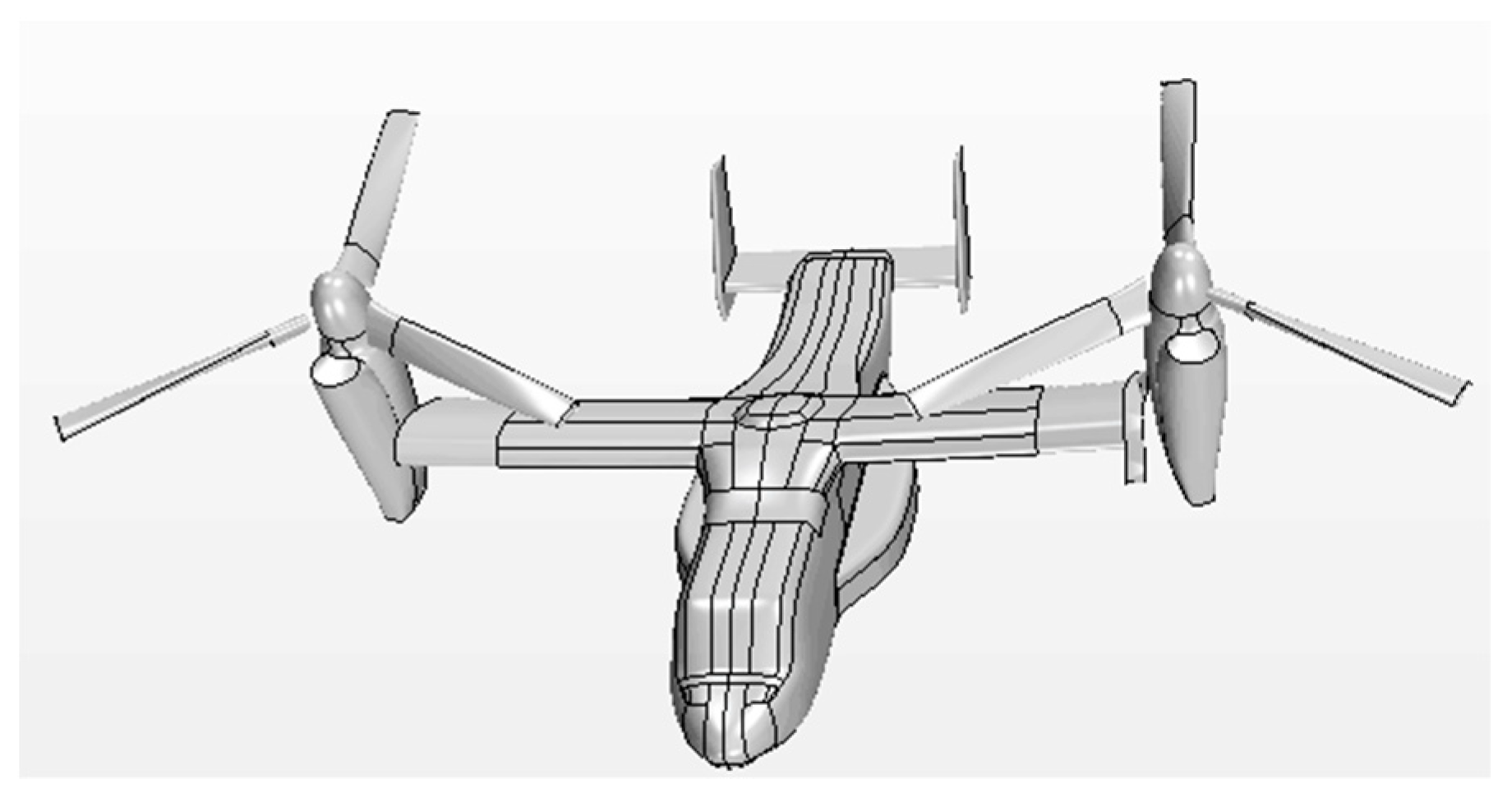
Figure 1 shows the geometry of the 0.658-scale V-22 model but, primarily, only the wing and the rotor were used for the study in the present paper. Due to the symmetry of the model, only half of the model is simulated. The geometrical characteristics and dimensions are reported in Table 1 (more details can be obtained from Felker [5]).
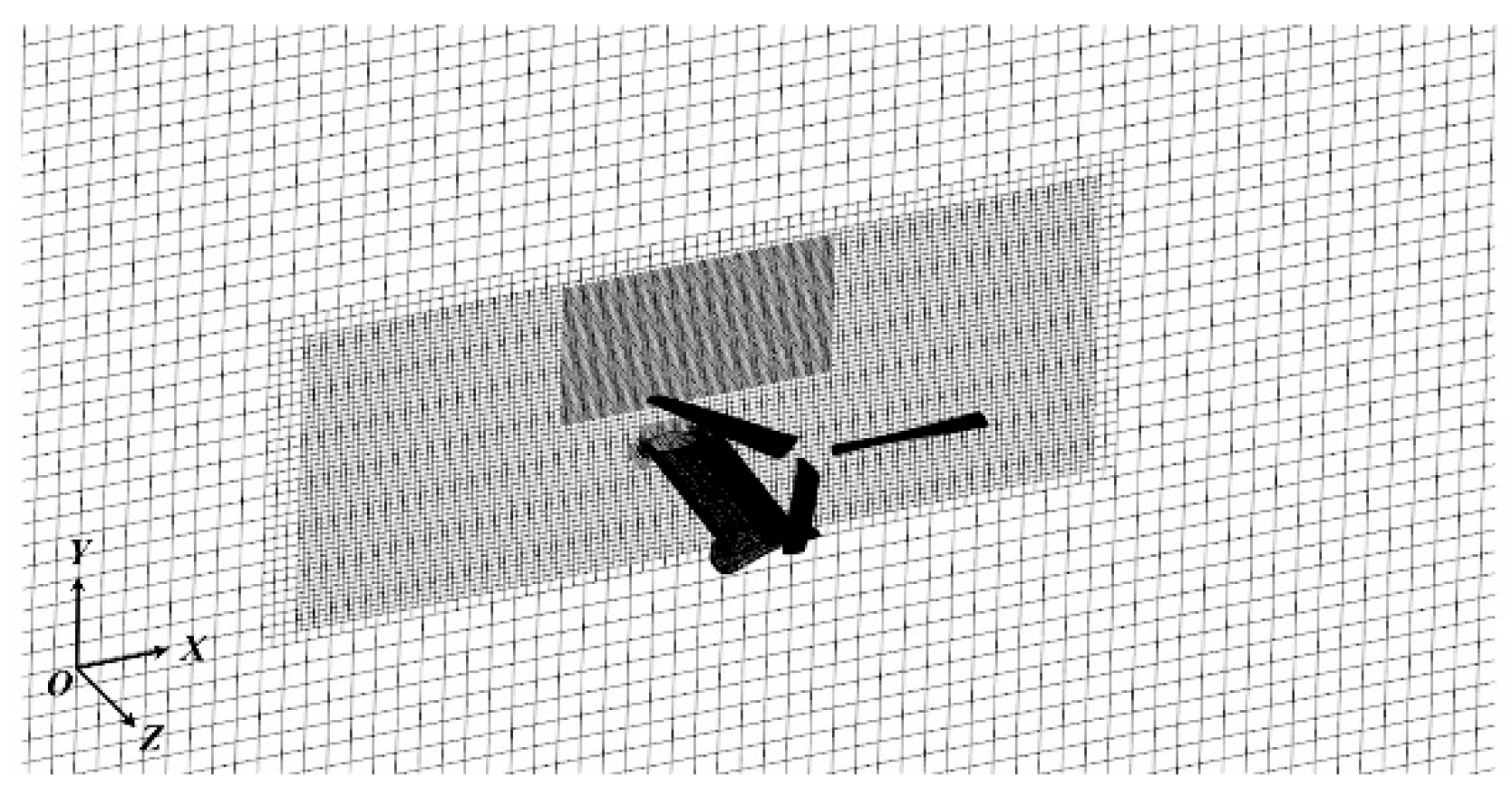
The hole-map method [13] for chimera mesh is adopted for the discretization of the computational domain. The general process of the mesh generation is as follows. Firstly, a background mesh for the farfield is established, which incorporates the wing as well. Local mesh density is performed near the overlapping region for the rotor as well as the regime near the wing. Afterwards, an individual rectangular grid block for one blade is generated. Local mesh density is established near the blade tip to obtain a better capture of the tip vortex effect. Subsequently, the blade block is duplicated twice and rotated correctly for the other two blades. Finally, the above four individual meshes are overset with each other to generate the interfaces of the eventual chimera grid, as shown in Figure 2. As for the boundary conditions, both the wing and blades surfaces are set as no-slip wall. The symmetry plane of the computational domain is right the aircraft symmetric plane. All the six boundaries of the farfield are set as velocity inlet.
The unsteady compressible Reynolds-averaged Navier–Stokes (RANS) equations are adopted to solve the flow field of interest. Although direct numerical simulation (DNS) solves the time-dependent Navier–Stokes equations by resolving a wider range of spatial and temporal scales of turbulence and, thus, can show much more details of flow features than RANS, and research on DNS of low-speed wind turbine rotational flow has emerged recently [14], simulating high Reynolds number flow, like in the present study, is not feasible even with today’s most powerful supercomputers. The rotating reference frame is attached to the rotating and tilting blades to formulate RANS equations for moving grids. The governing differential equations can be written in conservation law form in a generalized Cartesian coordinate system as follows [15]:
Q i t + ( E i E v i ) x i = S i
where the Cartesian coordinate system x = ( x , y , z ) is attached to the blades with the origin overlapped with the hub center in the rotor rotating plane. t denotes time, Q the vector of conserved quantities, S the source term accounting for the centrifugal acceleration of the rotating blades, and E and E v are the vectors of inviscid and viscous fluxes, respectively. The subscript i stands for the corresponding variable in the three coordinate directions. They are given by
Q = [ ρ ρ u ρ v ρ w e ] ,   S = [ 0 ρ ( Ω z v Ω y w ) ρ ( Ω x w Ω z u ) ρ ( Ω y u Ω x v ) 0 ]
E = [ ρ u ρ u 2 + p ρ u v ρ u w u ( e + p ) + q x R e P r , ρ v ρ u v ρ v 2 + p ρ v w v ( e + p ) + q y R e P r , ρ w ρ u w ρ v w ρ w 2 + p w ( e + p ) + q z R e P r ]
E v = 1 R e [ 0 τ x x τ x y τ x z u τ x x + v τ x y + w τ x z , 0 τ x y τ y y τ y z u τ x y + v τ y y + w τ y z , 0 τ x z τ y z τ z z u τ x z + v τ y z + w τ z z ]
where R e is Reynolds number and P r is Prandtl number. u = ( u , v , w ) and Ω = ( Ω x , Ω y , Ω z ) are, respectively, the velocity and angular velocity components in the corresponding directions of ( x , y , z ) , q = ( q x ,   q y ,   q z ) heat flux components, ρ density, e total energy, p static pressure, and τ shear stress, described below.
The Menter SST (Shear Stress Transport) k-ω turbulence model [16] has been widely validated to be suitable for flows with adverse pressure gradients and large rotations, especially for various rotor flows [17,18,19,20,21]. Particularly, Kau et al. [20] conducted a comparison between HMB (Helicopter Multi-Block) and CFD data using the OVERFLOW2 solver, where the SST k-ω turbulence model was employed. A fair agreement was found for the surface pressure coefficient at all radial stations. Yoon et al. [21] compared the figure or merit (FM) obtained by the SST k-ω model with those from the SA (Spalart-Allmaras) model and experiments, and found that the FM using the SST model has only a 0.9% relative error with respect to the experimental result, and is slightly closer to experimental results than the SA FM. A recent work from the current research group also showed that the SST k-ω model is suitable for rotor rotational flows [22]. Therefore, with reference to the practice of many other studies and our own experience on rotor flows, the SST k-ω model is also utilized to model the turbulence effect in the present study. It is a combination of the original k-ω model and the k-ε model, which is obtained by the original k-ω model multiplied by a function F 1 plus the transformed k-ε model multiplied by a function 1 F 1 . The kinematic eddy viscosity equation of Menter SST k-ω turbulence model [14] is written as
D ( ρ k ) D t = τ i j u i x j β * ρ ω k + x j [ ( μ + σ k μ t ) k x j ]
D ( ρ ω ) D t = γ v t τ i j u i x j β ρ ω 2 + x j [ ( μ + σ ω μ t ) ω x j ] + 2 ( 1 F 1 ) ρ σ ω 2 1 ω k x j ω x j
where τ i j = μ t ( u i x j + u j x i 2 3 u k x k δ i j ) 2 3 ρ k δ i j . v t is the eddy viscosity defined as v t = a 1 k max ( a 1 ω ;   ϑ F 2 ) , where ϑ is the absolute value of the vorticity and F 2 is a function defined below. Let ϕ 1 , ϕ 2 , ϕ represent any constant in the original k-ω model, k-ε model, and the above SST k-ω model, respectively. Then, the relation between them is
ϕ = F 1 ϕ 1 + ( 1 F 1 ) ϕ 2
F 1 = tanh ( arg 1 4 ) ,   F 2 = tanh ( arg 2 2 )
arg 1 = min [ max ( k 0.09 ω y ; 500 v y 2 ω ) ;   4 ρ σ ω 2 k C D k ω y 2 ] ,   arg 2 = max ( 2 k 0.09 ω y ; 500 v y 2 ω )
The constants of set 1 ( ϕ 1 ) are
σ k 1 = 0.85 ,   σ ω 1 = 0.5 ,   β 1 = 0.075 ,   a 1 = 0.31 β * = 0.09 ,   κ = 0.41 ,   γ 1 = β 1 / β * σ ω 1 κ 2 / β *
The constants of set 2 ( ϕ 2 ) are
σ k 2 = 1.0 ,   σ ω 2 = 0.856 ,   β 2 = 0.0828 β * = 0.09 ,   κ = 0.41 ,   γ 2 = β 2 / β * σ ω 2 κ 2 / β *
Numerical activities were carried out, including the isolated rotor in hover, wing, and rotor in hover and transition. The rotor rotating and tilting rates are 53.94 and 0.1047 rad/s, respectively. In order to assure the simulation fidelity of the transition process, as well as the numerical convergence, the time step size of 9.7 × 10⁻⁴ s is chosen for no-tilt cases so that the rotor rotates 3 degrees per time step, while for cases with rotor tilt motions it is set as 8.33 × 10⁻⁴ so that the rotor tilts about 0.005 degrees per time step. The numerical results of the rotor in hover are compared with the experimental data to show the validity of the present solver. The simulations of the wing and rotor in transition were analyzed by two methods: a quasi-steady method and a fully transient method. The grid dependence was studied when the rotor shaft was at 0 degree in transition using the quasi-steady method.

3. Results and Discussions

3.1. Isolated Rotor in Hover

In this subsection, the case of an isolated rotor in hover is conducted in order to check the accuracy of the current solver. The number of cells in each part of the grid is shown in Table 2.
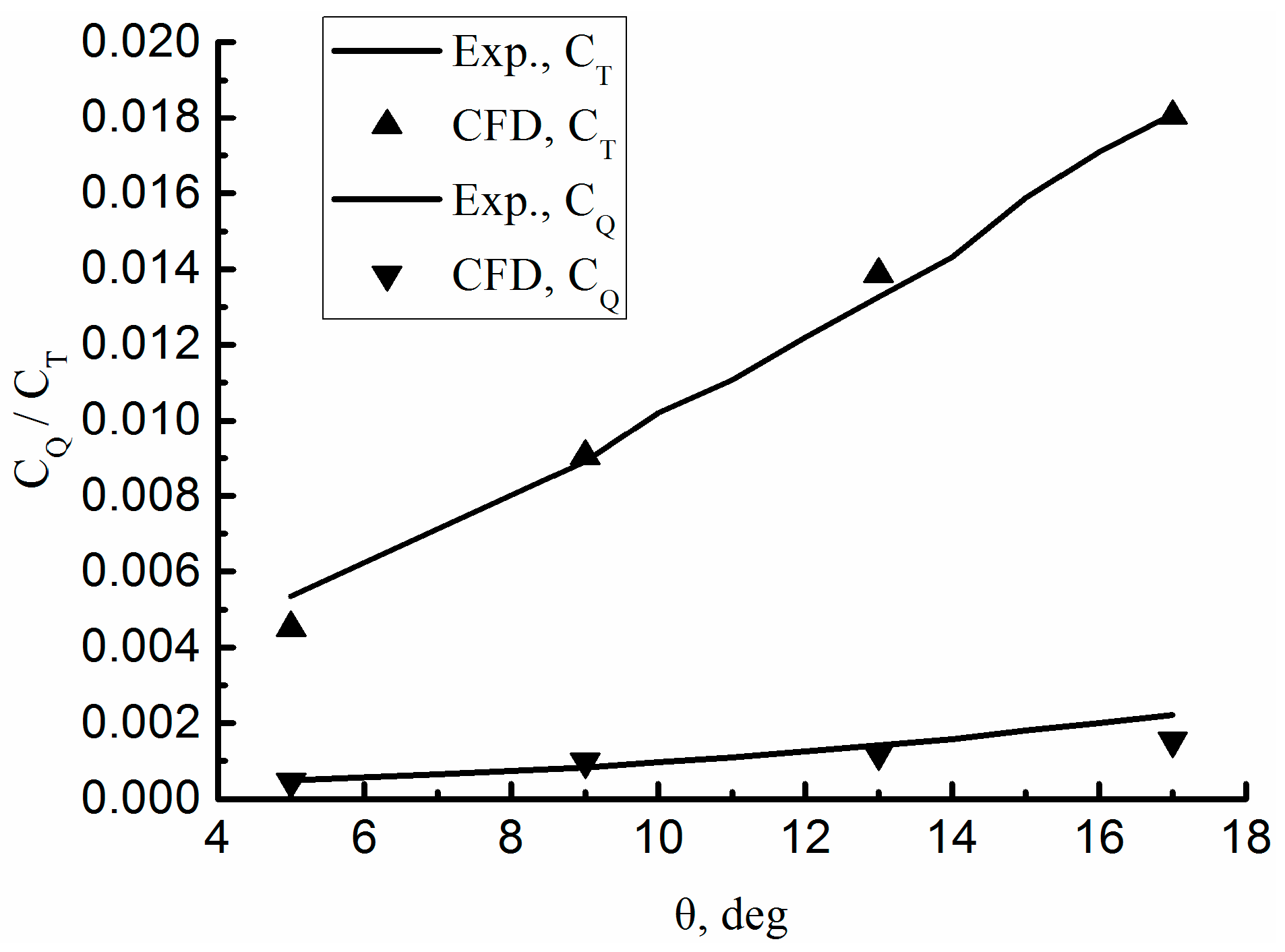
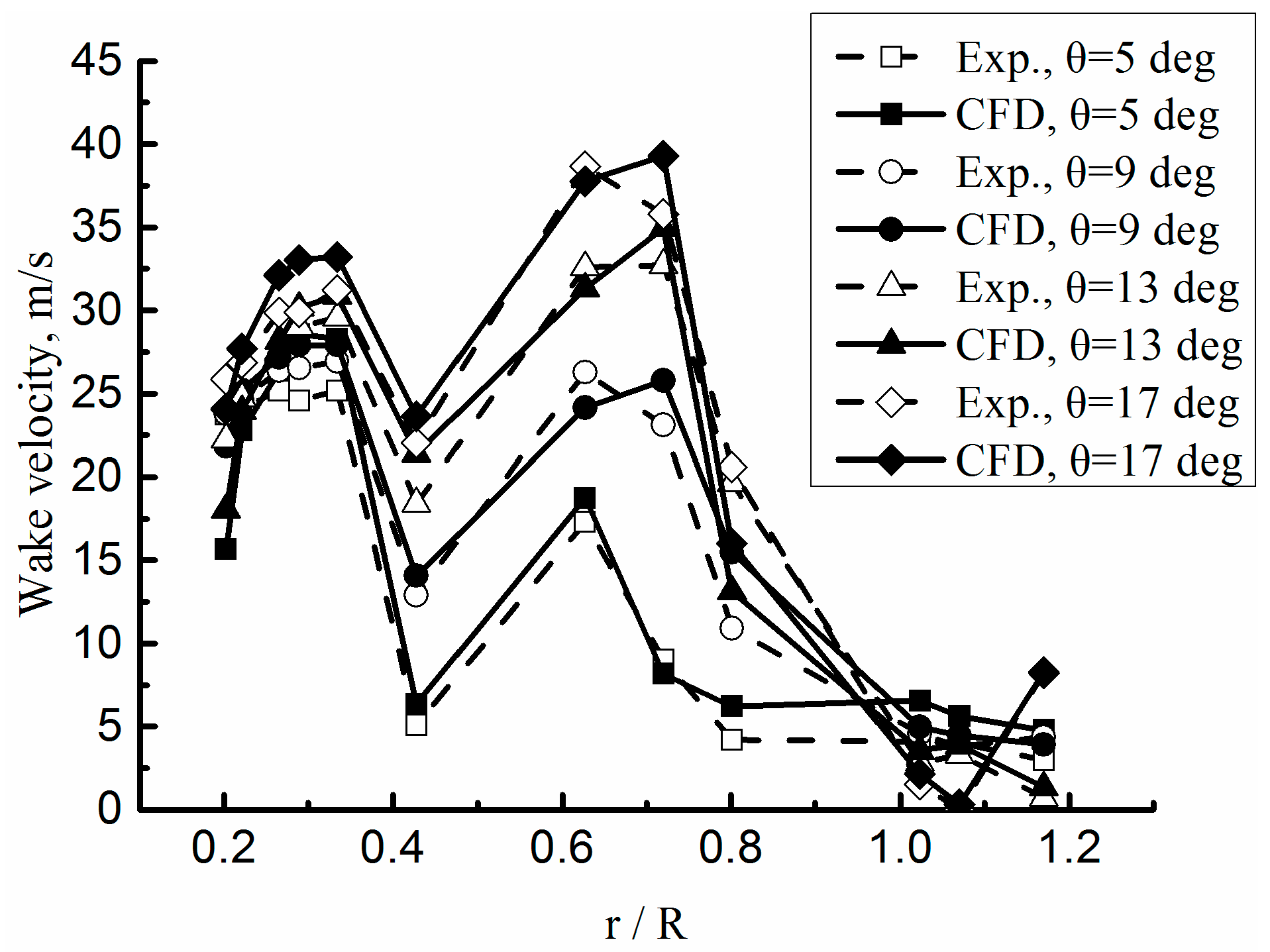
The thrust (CT) and torque (CQ) coefficients at the selected blade collective angle (θ) are extracted from the solutions and compared with the experimental data in [5], as shown in Figure 3. The numerical CT and CQ curves show good agreement with the experimental data. Figure 4 shows a comparison between the predicted and experimental results for the wake velocity. The same reference as in Figure 3 is utilized. It is observed that the trends of wake velocity of our simulations overall agree well with the experiment with some slight difference in magnitude. In general, the accuracy of the current flow solver can be accepted.

3.2. Wing and Rotor in Hovering Helicopter Mode

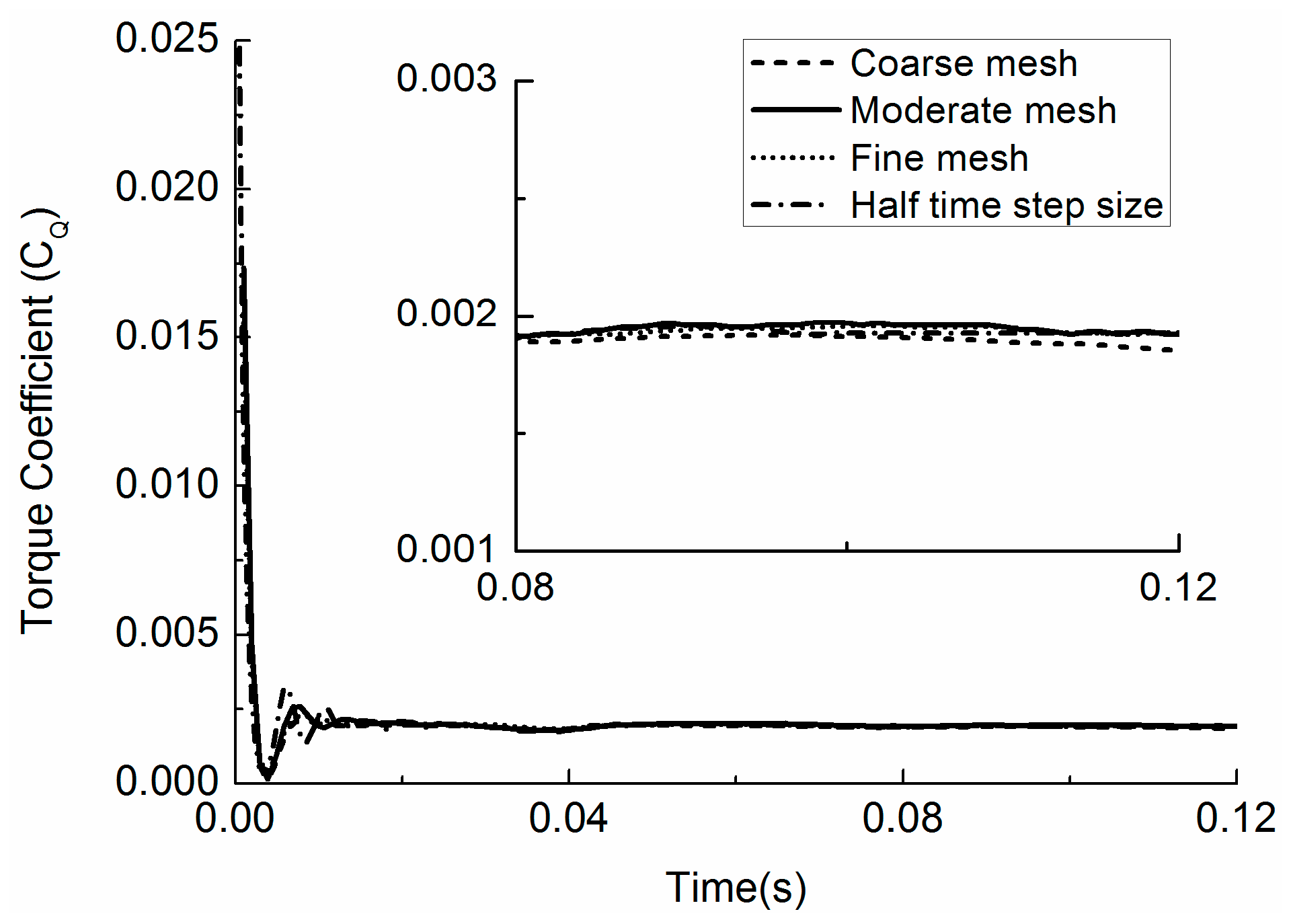
In this subsection, the flow field with both the wing and rotor is simulated. The rotor rotates at the same angular velocity as above, and there is no freestream air velocity in the farfield. Firstly, grid independence is examined in the case of 9-degree collective angle with three resolution grids, shown in Table 3. The time histories of rotor torque coefficient shown in Figure 5 indicate that the difference between the moderate and fine grids has reached a negligible degree (details can be seen from the zoomed view of the final steady state in the inset of Figure 5). In order to evaluate the influence of time step size on the calculation results, a half time step size, i.e., 4.85 × 10⁻⁴ s, is used, with the moderate mesh and the corresponding result is also plotted in Figure 5. Although there is an unexpected oscillation in the curve for the smaller time step size before about 0.11 s, the result finally becomes smooth and coincides well with that with the moderate mesh size and baseline time step size. In addition, the values of the torque coefficient at the final steady state for the different cases are listed in Table 4, as well as the relative error with respect to the moderate mesh case. It can be seen that further increasing the mesh resolution and decreasing the time step size results in a difference of less than 1% of the moderate mesh results. Therefore, the moderate grid resolution and the baseline time step size are selected for all the following calculations of the rotor and wing.
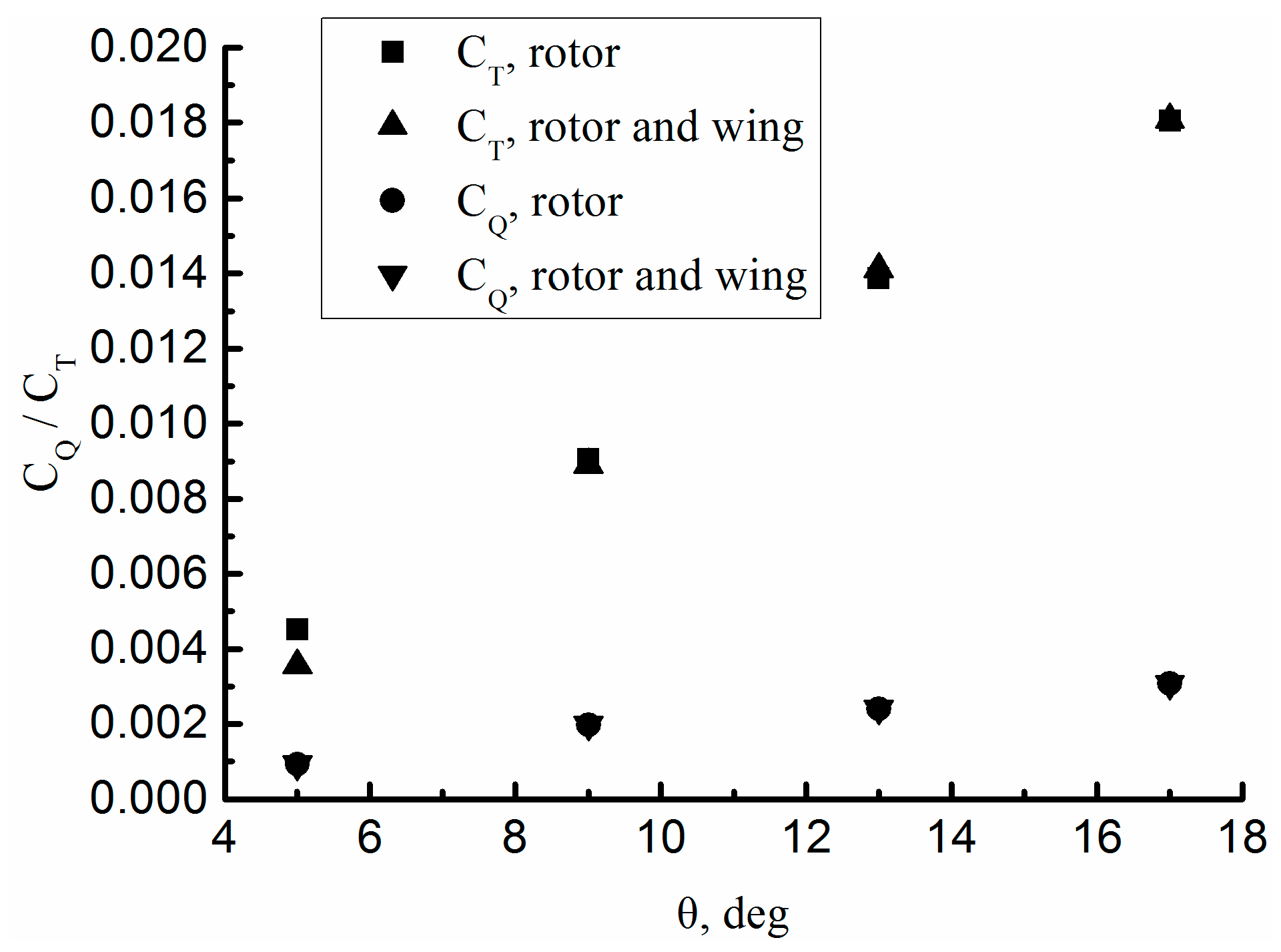
Figure 6 presents a comparison of the predicted rotor thrust and torque coefficients between the two cases. It indicates that the presence of the wing does not impart much influence on the aerodynamic coefficients for the rotor.
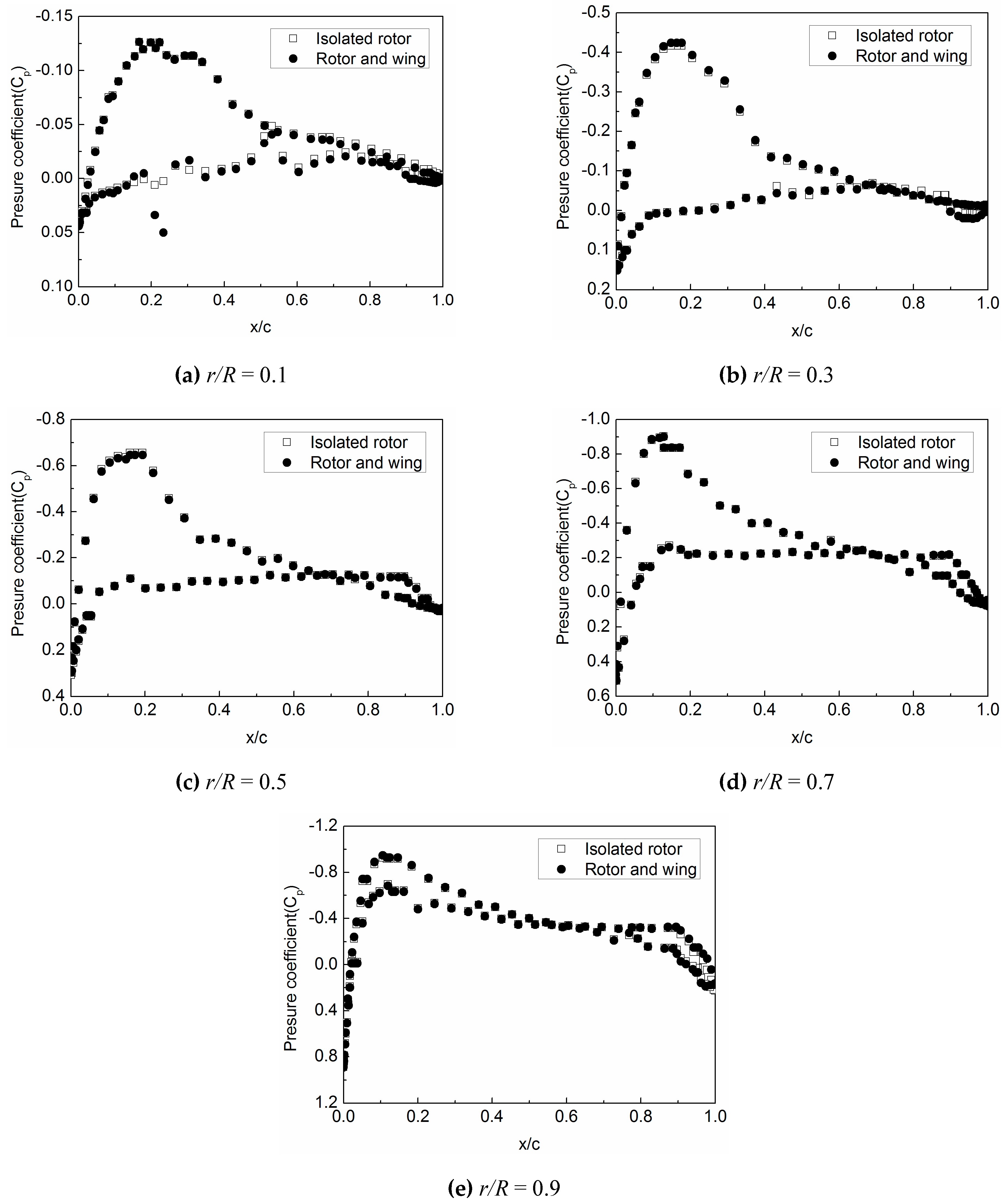
Figure 7 plots the pressure coefficients of the sections at several spanwise positions on the blade. Note that, here, the distance is measured from the blade root to the tip, and the total distance “R” is the total spanwise length of the blade, excluding the vacancy between the hub center and the blade root. It is found that there is slight deviation in the pressure coefficients between the cases with and without the wing. However, this deviation is insufficient to make significant changes in the aerodynamic forces on the rotor, as shown in Figure 6.

3.3. Wing and Rotor in Forward Flight Transition Mode

In this subsection, the V-22 wing at zero angle of attack (AOA) is added into the computational flow field. To simulate the wing–rotor interaction in the transition mode, both a quasi-steady method and a fully transient method are implemented for comparison. In the quasi-steady method, the rotor shaft was fixed at eight tilt angles (TA) relative to the vertical direction: 0, 5, 10, 15, 30, 45, 60, and 75 degrees, and simulations were conducted for the rotor rotating along the shaft at these tilt positions. In the transient method, the rotor shaft is tilting at a rate of 6 degrees per second. The incoming air flow velocity is 61.65 m/s. In practice, numerical divergence occurred in the fully transient simulations soon after the rotor tilts to 75 degrees. This situation always emerged even if we attempted refining the mesh within our computational capability.
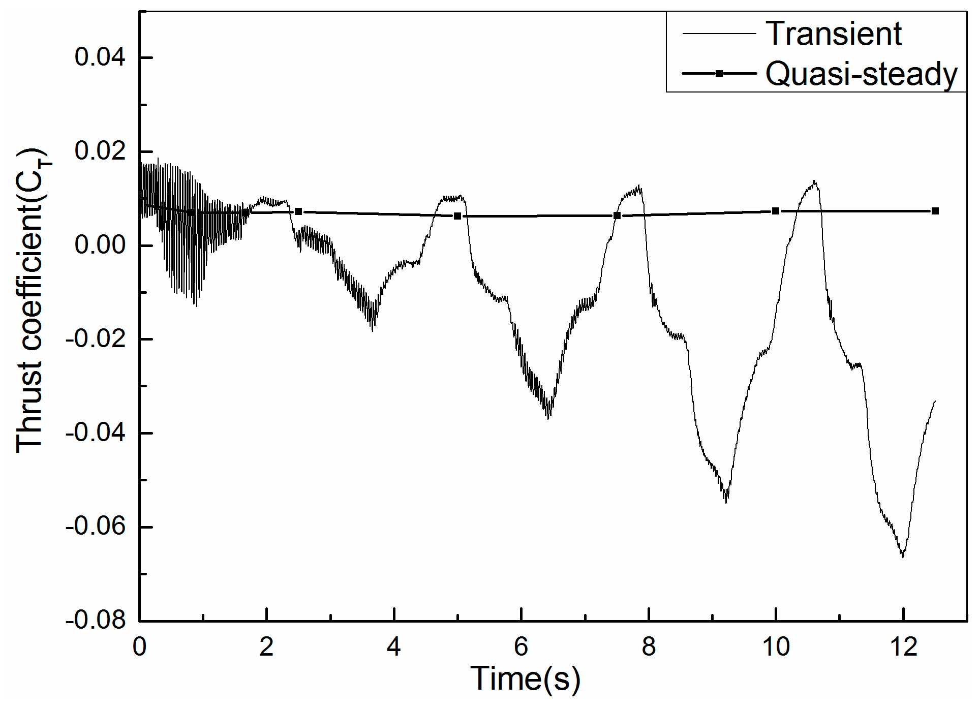
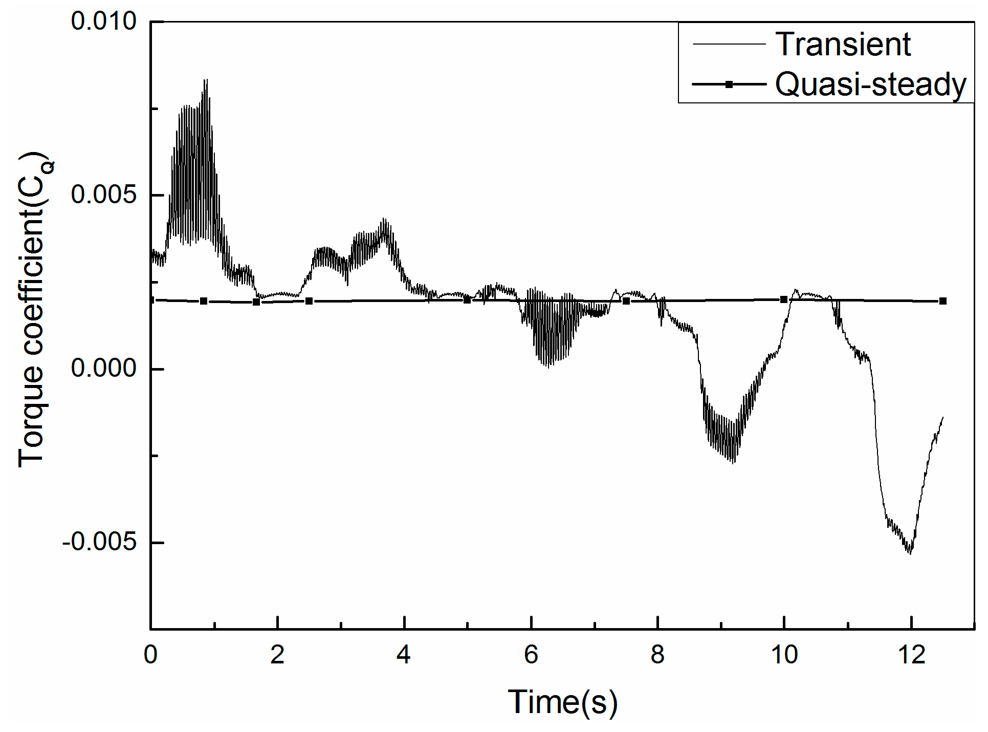
Figure 8 and Figure 9 respectively show the CT and CQ of the rotor via the two methods, respectively. For both variables, the values are almost constant as for the quasi-steady method. However, using the transient method, the two variables undergo sharp fluctuations with increase in the amplitude while decrease in the mean value. This may be explained as follows. As the TA increases, the wing is more exposed in the downwash of the rotor, which is validated by the isosurface contour of vorticity ( | Ω | = 50 rad/s), shown in Figure 10. Thus, the oscillation amplitudes of the rotor thrust and torque increase. Simultaneously, the blockage effect of the wing on the rotor downwash flow becomes stronger with the increasing TA, resulting in gradual decrease in the mean values of the rotor thrust and torque.
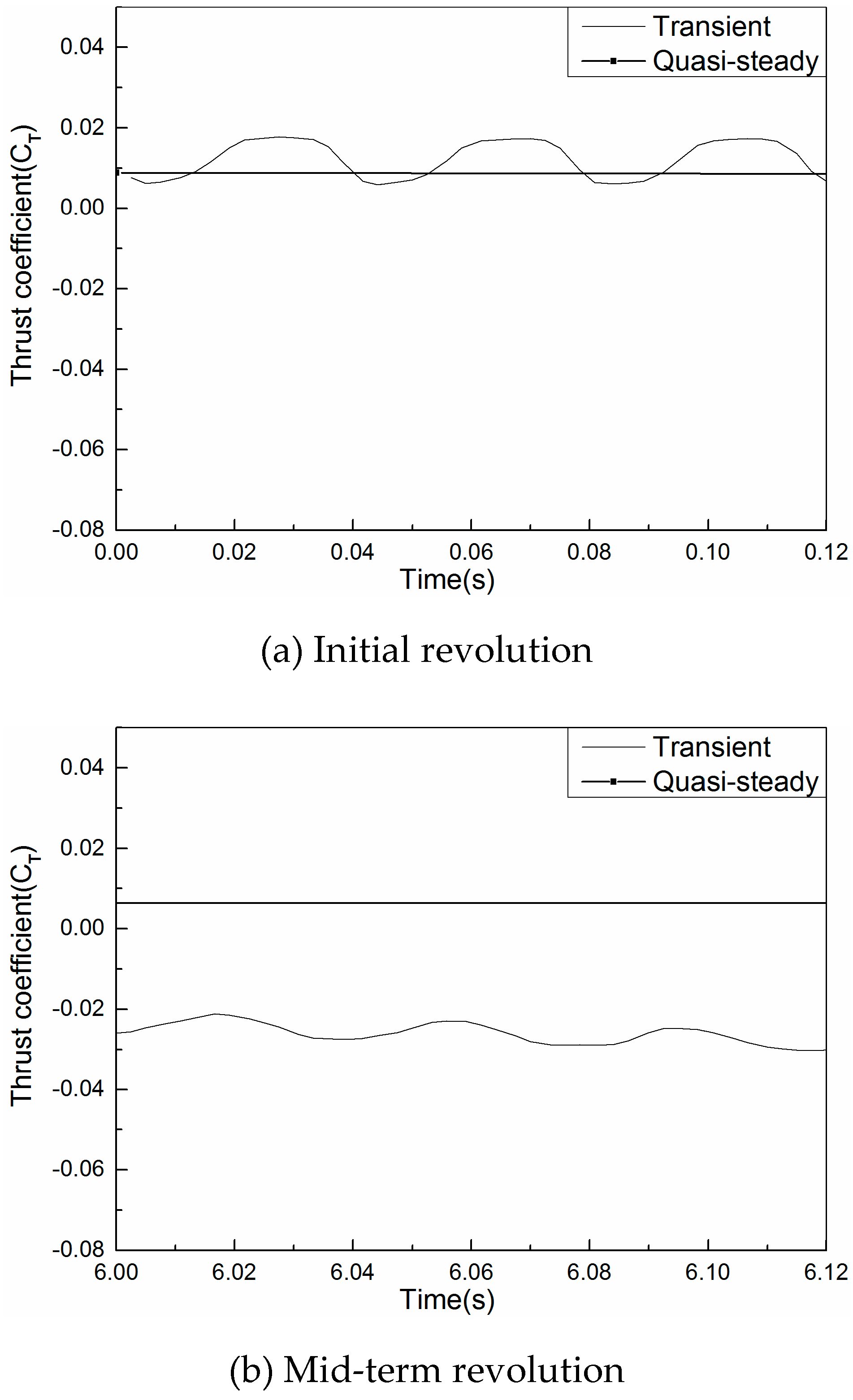
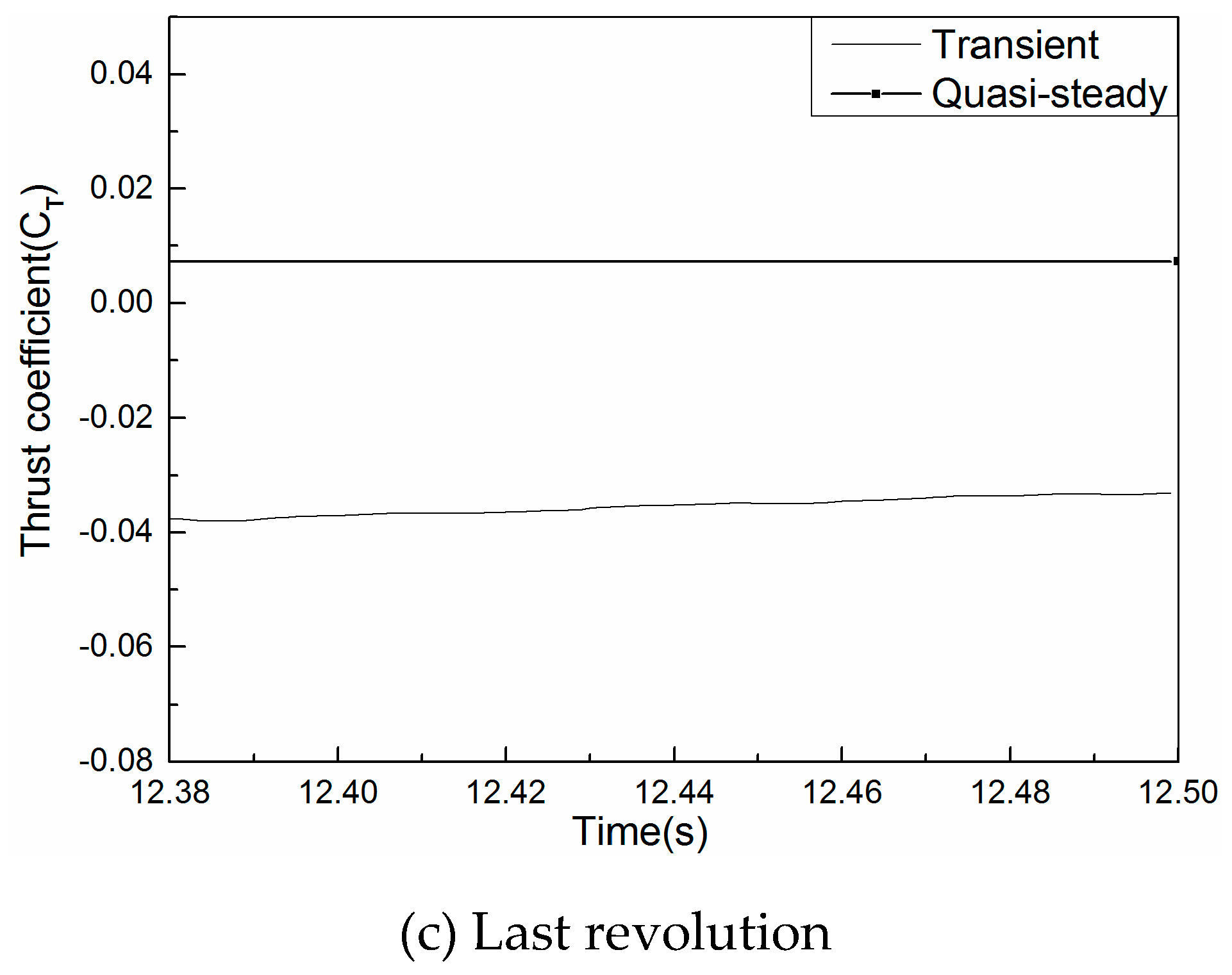
Shown in Figure 11 are zoomed views of the evolution of the rotor thrust coefficient (the revolution period is about 0.12 s). A pattern of three waves per revolution is observed, which is a typical result of the three-bladed rotor. Towards the end of the simulation, the waves become more and more level and stable. Similar conclusions were drawn by Droandi, et al. [9], where there are four waves within one revolution period for a four-bladed rotor.
Table 5 and Table 6 respectively present comparisons of the thrust and torque coefficients of the rotor at several TAs by the two methods. Generally, the values computed by the transient method are larger than those by the quasi-steady method. This is largely owed to the unsteadiness of the flow field and the centrifugal force due to the real rotation of the rotor, both of which are incorporated in the transient tilt modeling method. In the real world, the rotor tilt motion is a continuous process, thus, previous flow field characteristics greatly affect the later. In addition, the centrifugal force due to the rotor tilt motion provides the rotor with an additional velocity of approximately 0.25 m/s (the rotor radius of gyration is 2.35 m and the tilting rate is 0.1047 rad/s), which may not be ignored, especially at the rotor root.
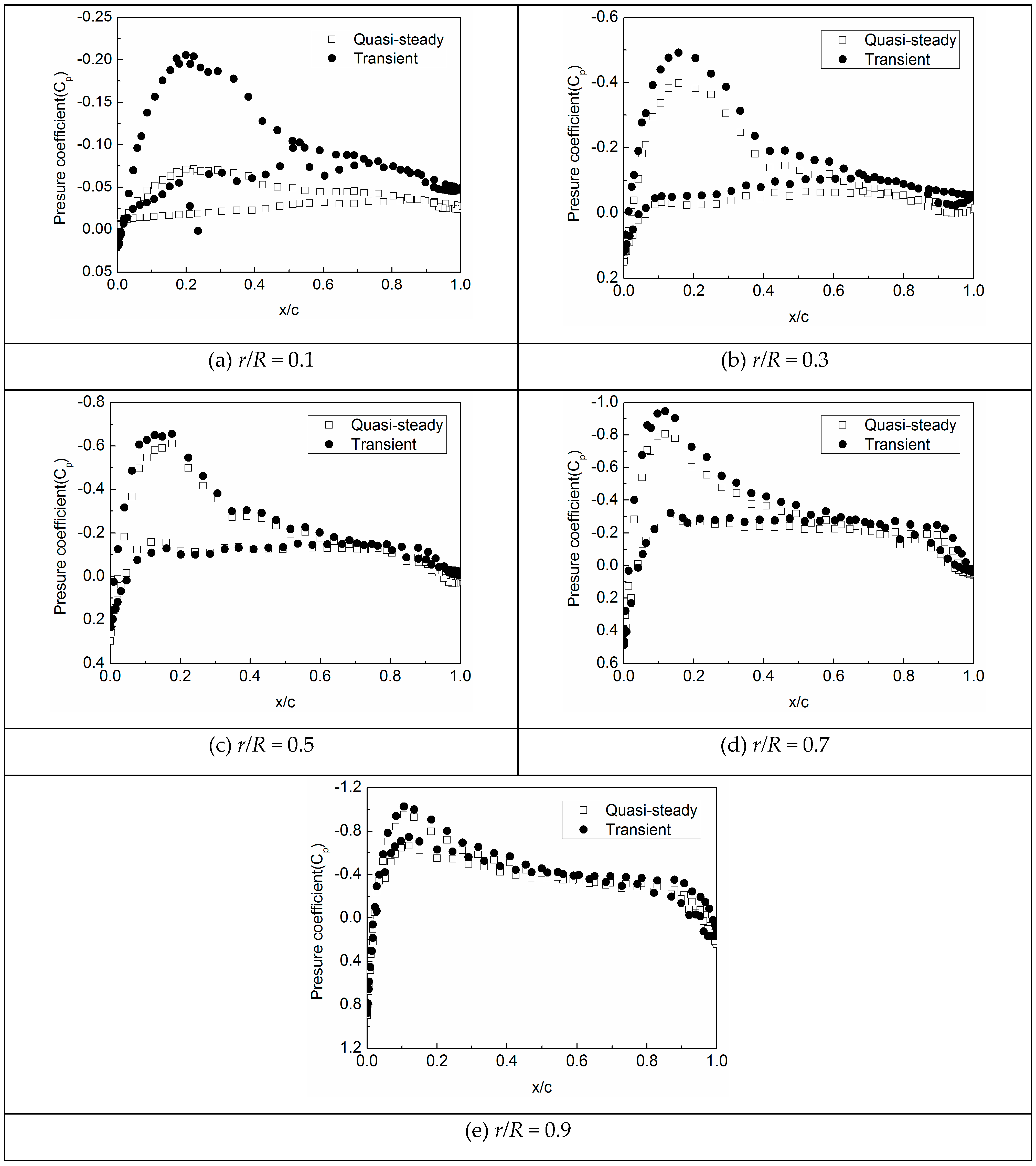
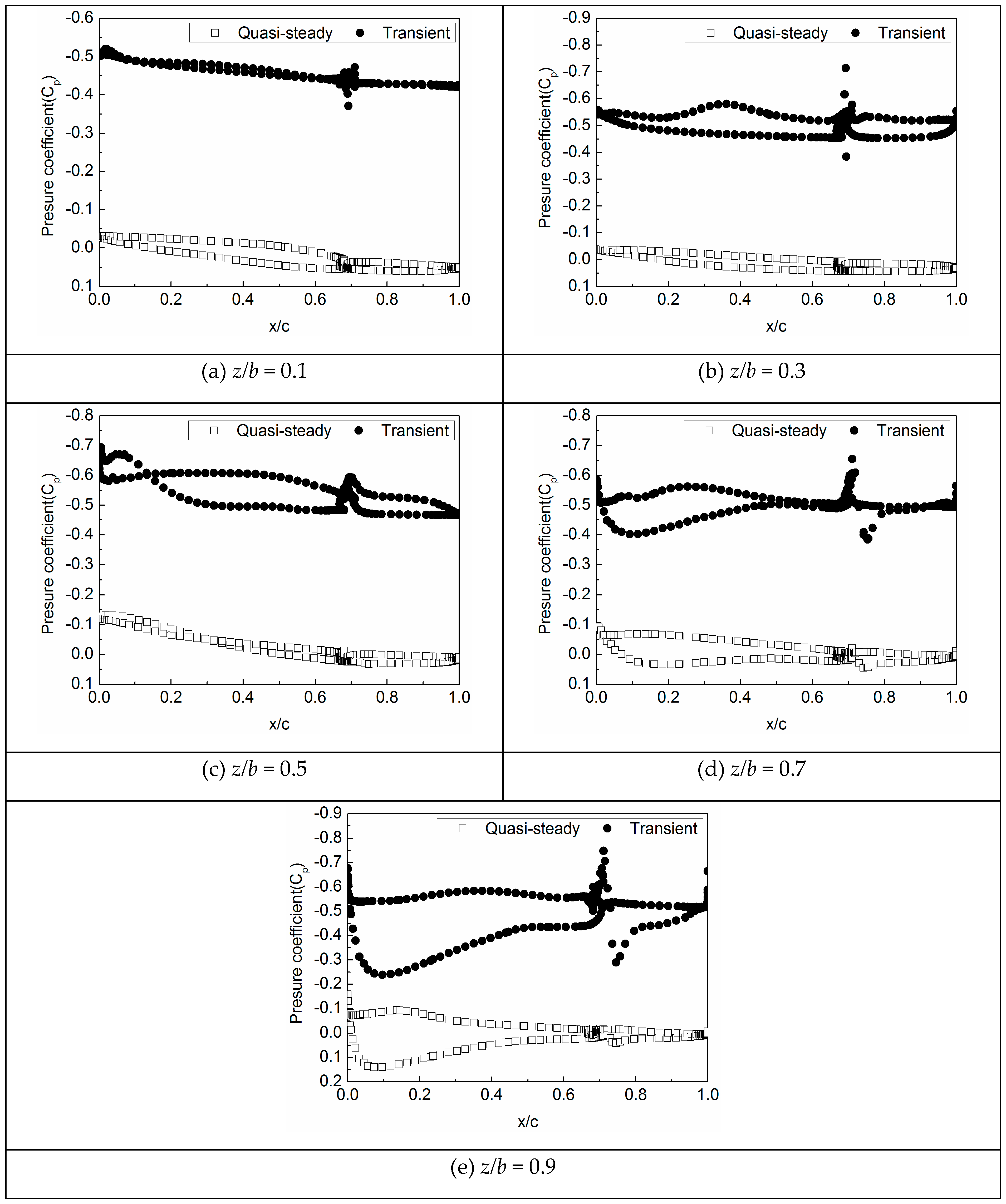
Figure 12 plots the pressure coefficient distributions at several radial positions on the blade at TA = 30 degrees. The distinction between the two methods can be clearly observed. The pressure difference between the lower and upper surfaces of the blade obtained by the transient method is significantly larger than that by the quasi-steady method, especially for the inboard positions. This validates the results shown in the above two tables. In addition, towards the blade tip, the pressure coefficients obtained by the quasi-steady method matches more closely with the transient results, since the velocity supplied by the centrifugal force on the rotor mentioned above becomes less. This finding is very important as it implies the applicability of the extensively utilized quasi-steady method.
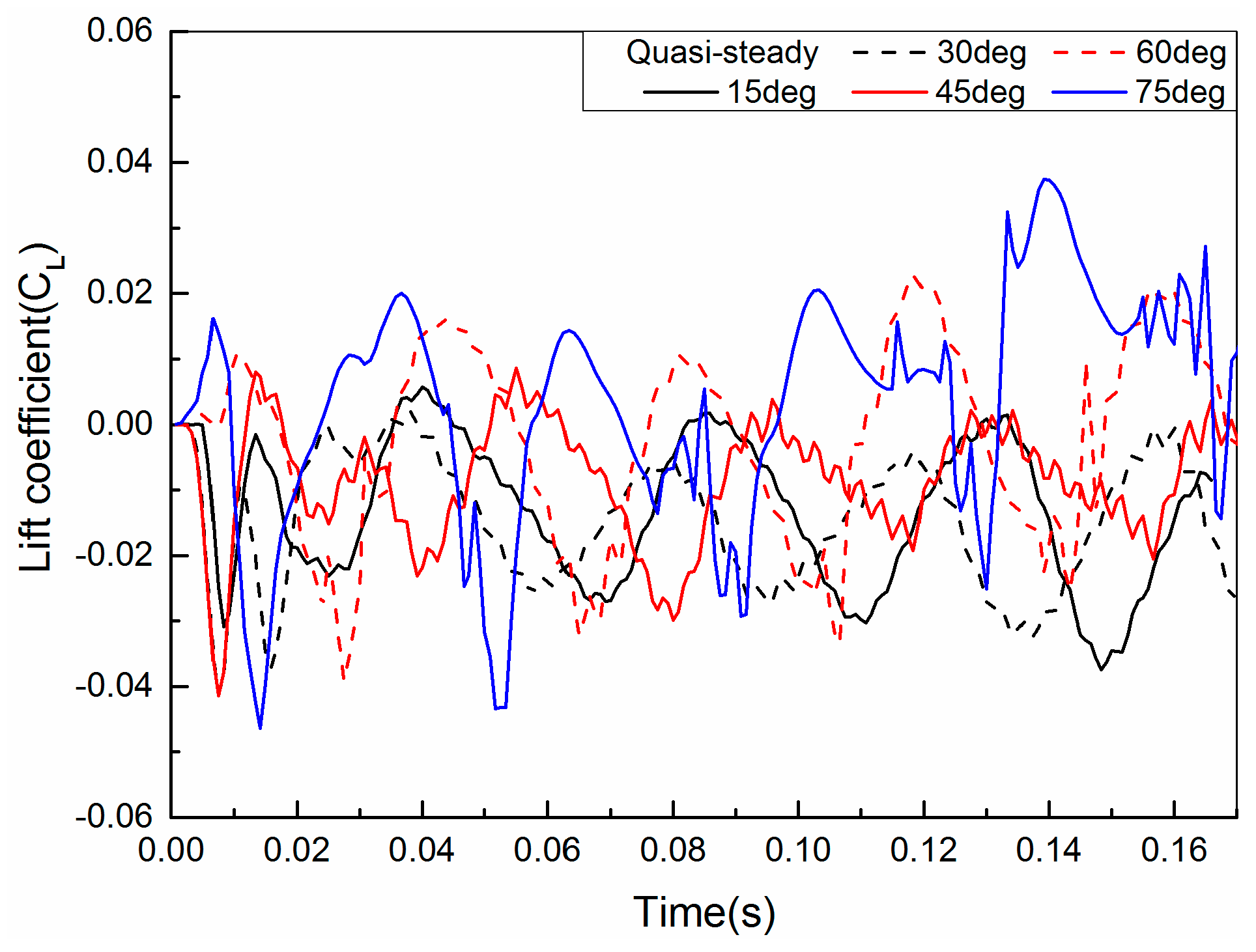
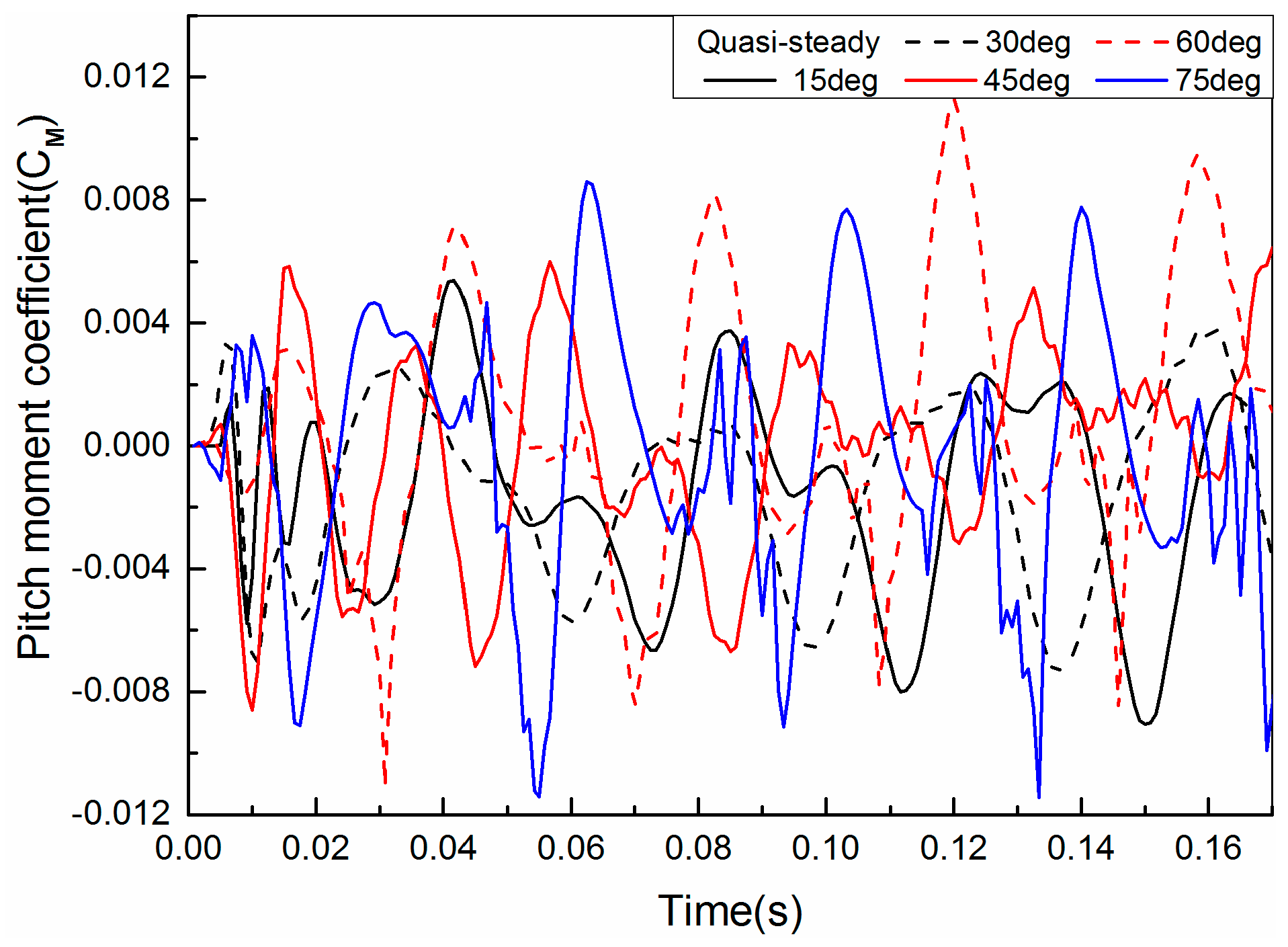
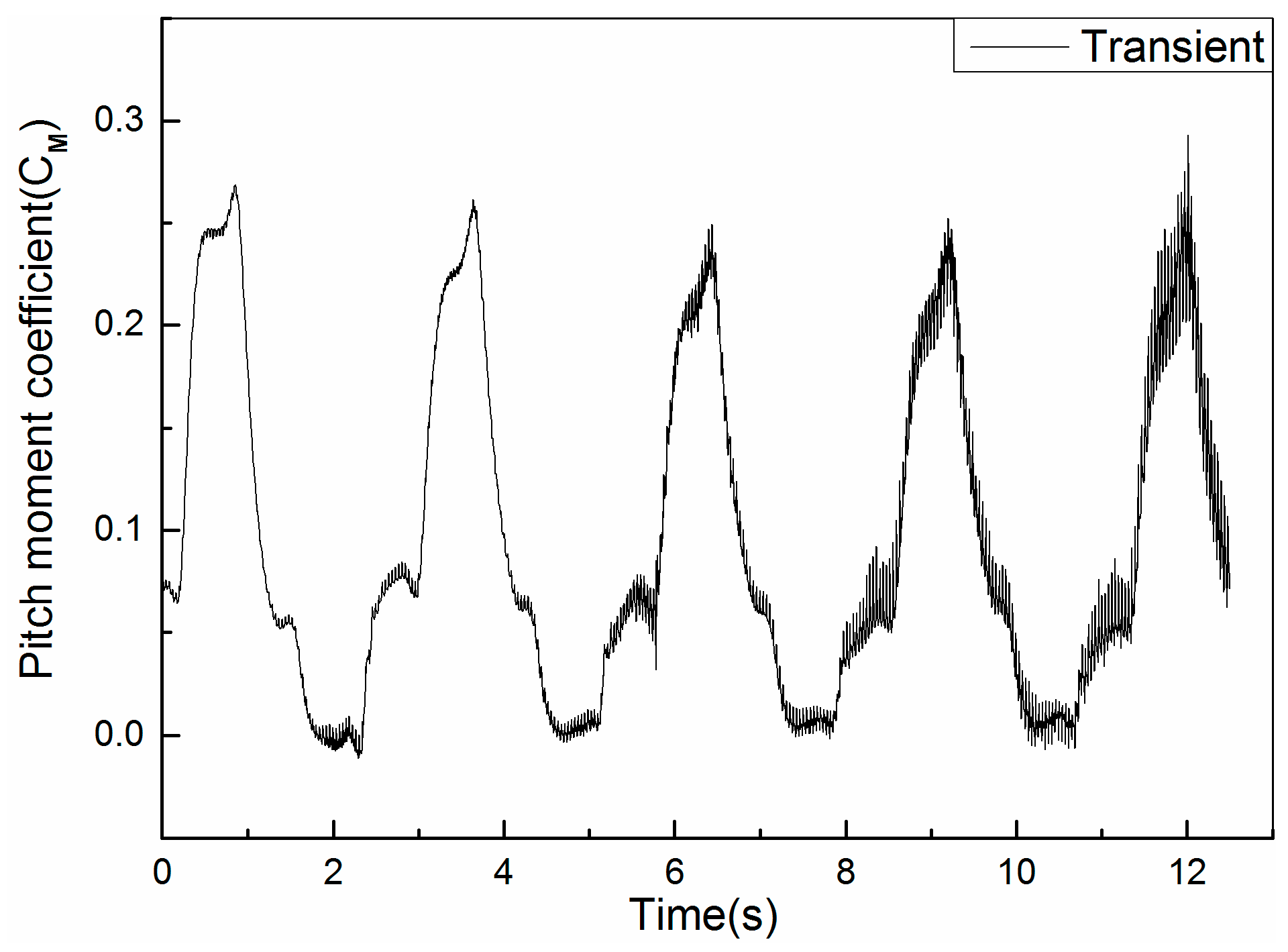
Figure 13 and Figure 14 respectively show the time histories of the lift (CL) and pitching moment (CM) coefficients of the fixed wing at different TAs using the quasi-steady method. Due to the periodic downwash impacting the wing, the lift and pitching moment of the wing also exhibit periodic oscillations. However, no significant law can be found among the different TA cases. Correspondingly, the results calculated by the transient tilt modeling method from 0 to 75 degrees of TA are shown in Figure 15 and Figure 16, respectively. It is easily seen that as the TA increases, the oscillating frequencies of the force and moment become higher, which is because that the wing becomes more exposed in the downwash flow of the rotor and, thus, subject to stronger impact of the downwash.
Table 7 and Table 8 respectively present comparisons of the lift and pitching moment coefficients of the wing at several TAs by both methods. Compared with the results shown in Table 5 and Table 6 for the rotor, the difference between both methods seems much more significant for the wing, which can be reflected by the pressure coefficient distribution at the several spanwise sections of the wing, as shown in Figure 17.
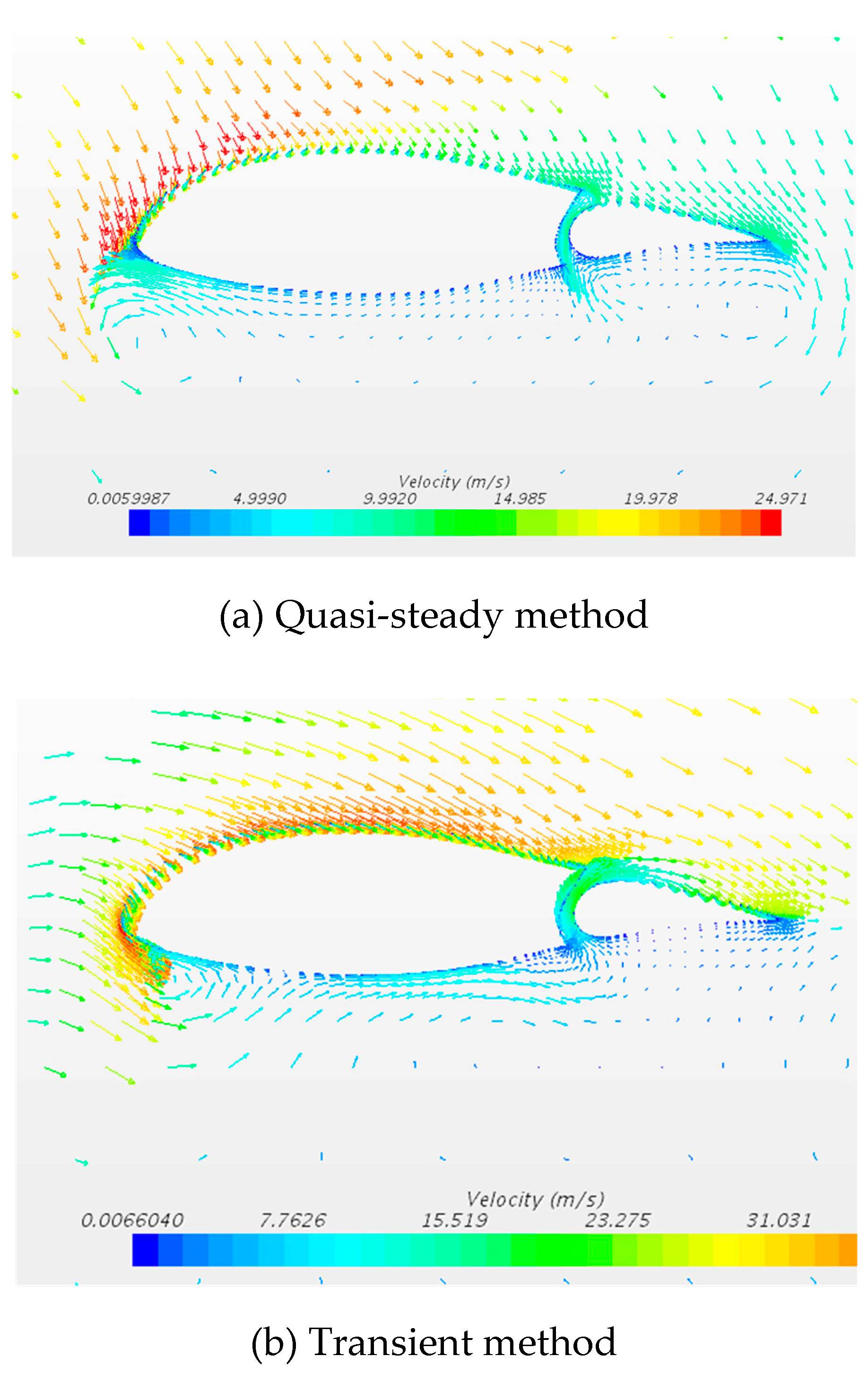
Taking the case of TA = 30 degrees as example, the velocity fields of the wing at the spanwise position z/b = 0.5 solved by the two methods are shown in Figure 18. It can be seen that the simulated rotor downwash influence on the wing is much larger using the quasi-steady method. The intense interaction between the rotor and wing causes two significant vortexes beneath the wing. However, with the transient method, the unsteadiness of the flow field and the temporal continuity of the rotor tilt motion are well considered. Thus, the mutual interaction becomes relatively gentle with the disappearance of the bottom vortexes, resulting in a significant downward shift in the pressure distributions, as plotted in Figure 17, as well as less negative lift on the wing as shown in Table 6. Overall, it seems that the aerodynamic performance predicted by the transient method is better than that by the quasi-steady method.

4. Conclusions

In this paper, a numerical investigation of the aerodynamic interactions between the rotor and wing of the V-22 Osprey tiltrotor in both the helicopter and transition modes is presented. The computational domains are discretized by chimera mesh technique and solved with the RANS equations with an additional source term to account for the centrifugal acceleration of the rotating blades.
The numerical accuracy is firstly validated by comparing the results for the isolated rotor case by the current simulation with the results from the wind tunnel experiment in the literature. Then, the case of wing and rotor in hovering helicopter mode was studied. It was found that the presence of the wing does not impart significant influence on the pressure distribution, as well as the aerodynamic forces on the rotor. Finally, the case of the wing and rotor in the transition mode at a constant forward flight velocity is simulated. Both a quasi-steady and a fully transient method are employed to simulate the tilt motion of the rotor in the transition process. It is indicated that remarkable difference appears between the results by the two methods. The transient method considers the unsteadiness of the flow field and the centrifugal force due to the real tilt motion of the rotor, thus provides better prediction accuracy.
On the one hand, the results presented in this paper provide some more insights into the flow physics and mechanisms in tiltrotor transition aerodynamics: (1) As the tilt angle increases, the wing is more largely exposed in the downwash of the rotor, and the aerodynamic interactions between the rotor and wing become more intense, causing increasing oscillation amplitudes in the rotor thrust and torque. Meanwhile, the blockage effect of the wing on the rotor downwash flow becomes stronger with the increasing tilt angle, resulting in gradual decrease in the mean values of the rotor thrust and torque. (2) The unsteadiness of the flow field and the centrifugal force due to the real rotation of the rotor are indispensible considerations for more accurate predictions of rotor and wing aerodynamic forces and moments in the transition mode. (3) As the tilt angle increases, the oscillation of the wing lift and pitching moment become more intense, which is also due to the larger exposed area of the wing in the rotor downwash.
On the other hand, through this paper, the limitations of the extensively used quasi-steady method for simulation of tiltrotor transition process are revealed: (1) As for the rotor aerodynamics, the quasi-steady method is only accurate at the blade tip positions. Due to its lack in consideration of the unsteadiness and centrifugal force in a real tilt motion of rotor, the accuracy of the quasi-steady method becomes worse at more inboard positions to the blade root. (2) As for the wing aerodynamics, the quasi-steady method is not able to simulate the temporally continuous flowfield characteristics near the wing, thus, it is recommend not use this method to predict the aerodynamics of the wing for a tiltrotor aircraft. These results are new and may be helpful for practical tiltrotor aerodynamic design and optimization.
Author Contributions

Conceptualization, Z.W. and Y.C.; Methodology, Z.W.; Software, Z.W.; Validation, Z.W.; Formal Analysis, Z.W. and C.L.; Investigation, Z.W. and C.L.; Resources, Y.C.; Data Curation, C.L.; Writing-Original Draft Preparation, C.L.; Writing-Review & Editing, Z.W. and Y.C.; Visualization, C.L.; Supervision, Y.C.; Project Administration, Z.W.; Funding Acquisition, Z.W.

Funding

This work was financially supported by the Aeronautical Science Foundation of China (grant number 20165751024).

Conflicts of Interest

The authors declare no conflict of interest.

Nomenclature

AOAangle of attack
CLwing lift coefficient
CMwing pitching moment
CPpressure coefficient
CQrotor torque coefficient
CTrotor thrust coefficient
e total energy
E vector of inviscid fluxes
E v vector of viscous fluxes
F 1 , F 2 function in the SST k-ω model
i subscript indicting axial components
p static pressure
P r Prandtl number
q heat flux component
Q vector of conserved quantities
r/Rnormalized blade spanwise position starting from the root
R e Reynolds number
S source term
TAtilt angle
x Cartesian coordinate
u vector of air velocity
ρ air density
σ rotor solidity
ϕ , ϕ 1 , ϕ 2 constants in the SST, original, and k-ε turbulence models, respectively
τ Reynolds shear stress
v t eddy viscosity
θblade collective angle
ϑ absolute value of vorticity
Ω vector of rotor angular velocity

References

  1. Foster, M. The future evolution of the tiltrotor. In Proceedings of the AIAA/ICAS International Air and Space Symposium and Exposition: The Next 100 Years, Dayton, OH, USA, 14–17 July 2003. [Google Scholar]
  2. Choi, S.W.; Kang, Y.; Chang, S.; Koo, S.; Kim, J.M. Small tiltrotor UAV development and conversion flight test. Feedback 2008, 3, 4. [Google Scholar]
  3. Gennaretti, M.; Colella, M.M.; Bernardini, G.; Monteggia, C.; Fosco, E.; Ferro, P. Analysis of vibrations of an innovative civil tiltrotor. Aerosp. Sci. Technol. 2013, 29, 125–134. [Google Scholar] [CrossRef]
  4. Kakaley, D.E.; Jolly, M.R.; Buckner, G.D. An offset hub active vibration control system for mitigating helicopter vibrations during power loss: Simulation and experimental demonstration. Aerosp. Sci. Technol. 2018, 77, 610–625. [Google Scholar] [CrossRef]
  5. Felker, F.F.; Signor, D.B.; Young, L.A.; Betzina, M.D. Performance and Loads Data from a Hover Test of a 0.658-Scale V-22 Rotor and Wing; NASA: Washington, DC, USA, 1987.
  6. McCluer, M.S.; Johnson, J.L. Full-Span Tiltrotor Aeroacoustic Model FS TRAM Overview and Initial Testing; NASA Ames Research Center: Moffett Field, CA, USA, 2002.
  7. Tai, T.C. Simulation and analysis of V-22 tiltrotor aircraft forward-flight flow field. J. Aircr. 1996, 33, 369–376. [Google Scholar] [CrossRef]
  8. Potsdam, M.A.; Strawn, R.C. CFD simulations of tiltrotor configurations in hover. J. Am. Helicopter Soc. 2005, 50, 82–94. [Google Scholar] [CrossRef]
  9. Droandi, G.; Zanotti, A.; Gibertini, G. Aerodynamic interaction between rotor and tilting wing in hovering flight condition. J. Am. Helicopter Soc. 2015, 60, 1–20. [Google Scholar] [CrossRef]
  10. Droandi, G.; Gibertini, G.; Grassi, D.; Campanardi, G.; Liprino, C. Proprotor–wing aerodynamic interaction in the first stages of conversion from helicopter to aeroplane mode. Aerosp. Sci. Technol. 2016, 58, 116–133. [Google Scholar] [CrossRef]
  11. Garcia, A.J.; Barakos, G.N. Numerical simulations on the ERICA tiltrotor. Aerosp. Sci. Technol. 2017, 64, 171–191. [Google Scholar] [CrossRef] [Green Version]
  12. Zhao, M.; Cao, Y. Numerical simulation of rotor flow field based on overset grids and several spatial and temporal discretization schemes. Chin. J. Aeronaut. 2012, 25, 155–163. [Google Scholar] [CrossRef]
  13. Chiu, I.T.; Meakin, R. On automating domain connectivity for overset grids. In Proceedings of the 33rd Aerospace Sciences Meeting and Exhibit, Reno, NV, USA, 9–12 January 1995; p. 854. [Google Scholar]
  14. Ducoin, A.; Shadloo, M.S.; Roy, S. Direct Numerical Simulation of flow instabilities over Savonius style wind turbine blades. Renew. Energy 2017, 105, 374–385. [Google Scholar] [CrossRef]
  15. Available online: www.grc.nasa.gov/www/k-12/airplane/nseqs.html (accessed on 1 October 2018).
  16. Menter, F.R. Two-equation eddy-viscosity turbulence models for engineering applications. AIAA J. 1994, 32, 1598–1605. [Google Scholar] [CrossRef] [Green Version]
  17. Wekesa, D.W.; Wang, C.; Wei, Y.; Kamau, J.N.; Danao, L.A.M. A numerical analysis of unsteady inflow wind for site specific vertical axis wind turbine: A case study for Marsabit and Garissa in Kenya. Renew. Energy 2015, 76, 648–661. [Google Scholar] [CrossRef]
  18. Wekesa, D.W.; Wang, C.; Wei, Y.; Kamau, J.N.; Danao, L.A.M. Analytical and numerical investigation of unsteady wind for enhanced energy capture in a fluctuating free-stream. Energy 2017, 121, 854–864. [Google Scholar] [CrossRef]
  19. Menegozzo, L.; Monte, A.; Benini, E.; Benato, A. Small wind turbines: A numerical study for aerodynamic performance assessment under gust conditions. Renew. Energy 2018, 121, 123–132. [Google Scholar] [CrossRef]
  20. Kaul, U.; Ahmad, J. Skin friction predictions over a hovering tilt-rotor blade using OVERFLOW2. In Proceedings of the 29th AIAA Applied Aerodynamics Conference, Honolulu, HI, USA, 27–30 June 2011; p. 3186. [Google Scholar]
  21. Yoon, S.; Pulliam, T.H.; Chaderjian, N.M. Simulations of XV-15 rotor flows in hover using OVERFLOW. In Proceedings of the Fifth Decennial AHS Aeromechanics Specialists’ Conference, San Francisco, CA, USA, 22–24 January 2014; pp. 22–24. [Google Scholar]
  22. Wu, Z.; Bangga, G.; Cao, Y. Effects of lateral wind gusts on vertical axis wind turbines. Energy 2019, 167, 1212–1223. [Google Scholar] [CrossRef]
Figure 1. Geometric modeling of the V-22 tiltrotor.
Mathematics 07 00116 g001
Figure 2. Chimera grid for discretization of the rotor–wing flow field.
Mathematics 07 00116 g002
Figure 3. Comparison between the predicted and experimental results for the thrust and torque coefficients.
Mathematics 07 00116 g003
Figure 4. Comparison between the predicted and experimental results for the wake velocity.
Mathematics 07 00116 g004
Figure 5. Rotor torque coefficient obtained with three resolution grids and half time step size.
Mathematics 07 00116 g005
Figure 6. Predicted rotor thrust and torque coefficients for the isolated rotor and wing–rotor cases.
Mathematics 07 00116 g006
Figure 7. Pressure coefficient distributions on several blade sections for the isolated rotor and wing–rotor in hover. (a) r/R = 0.1; (b) r/R = 0.3; (c) r/R = 0.5; (d) r/R = 0.7;(e) r/R = 0.9.
Mathematics 07 00116 g007
Figure 8. Time history of the rotor thrust coefficient.
Mathematics 07 00116 g008
Figure 9. Time history of the rotor torque coefficient.
Mathematics 07 00116 g009
Figure 10. Isosurface vorticity near the rotor and wing with the transient method. TA is tilt angles.
Mathematics 07 00116 g010
Figure 11. An amplified local view of the time history of the rotor thrust coefficient within one revolution. (a) Initial revolution; (b) Mid-term revolution; (c) Last revolution.
Mathematics 07 00116 g011aMathematics 07 00116 g011b
Figure 12. Pressure coefficient distributions at several radial positions on the blade obtained by both methods. (a) r/R = 0.1; (b) r/R = 0.3; (c) r/R = 0.5; (d) r/R = 0.7;(e) r/R = 0.9.
Mathematics 07 00116 g012
Figure 13. Time history of the wing lift coefficient calculated by the quasi-steady method.
Mathematics 07 00116 g013
Figure 14. Time history of the wing pitching moment coefficient calculated by the quasi-steady method.
Mathematics 07 00116 g014
Figure 15. Time history of the wing lift coefficient calculated by the transient method.
Mathematics 07 00116 g015
Figure 16. Time history of the wing pitching moment coefficient calculated by the transient method.
Mathematics 07 00116 g016
Figure 17. Pressure coefficient distributions at several spanwise positions on the wing at TA = 30 degrees. (a) z/b = 0.1; (b) z/b = 0.3; (c) z/b = 0.5; (d) z/b = 0.7;(e) z/b = 0.9.
Mathematics 07 00116 g017
Figure 18. Velocity vector distribution near a wing section simulated by both methods. (a) Quasi-steady method; (b) Transient method.
Mathematics 07 00116 g018
Table 1. Geometric details of the 0.658-scale V-22 model [5].
Number of Blades3
Rotor radius7.62 m
Rotor airfoilXN-series
Mean blade chord0.513 m
Solidity, σ0.1138
Blade twist−47° (nonlinear)
Wing airfoilBell A821201
Wing chord1.76 m
Wing twist
Table 2. Number of cells in each part.
GridNumber of Cells (× 106)
Blade0.81 × 3
Farfield0.20
Total2.63
Table 3. Details of the three meshes for independence examination.
GridNumber of Cells (× 106)
CoarseModerateFine
Blade0.39 × 30.81 × 31.14 × 3
Farfield0.641.862.80
Total1.814.296.22
Table 4. Value and relative error of the torque coefficient (CQ) at the final steady state.
CaseCQΔ
Coarse mesh1.8684 × 10−32.76%
Moderate mesh1.9200 × 10−3/
Fine mesh1.9273 × 10−30.38%
Half time step size1.9256 × 10−30.29%
Table 5. Rotor thrust coefficient at several TAs by both methods.
TA (Degrees)Quasi-SteadyTransient
50.006890.0133
100.007040.00737
150.007280.00813
300.006330.00984
450.006490.00718
600.00748−0.0143
750.00756−0.0331
Table 6. Rotor torque coefficient at several TAs by both methods.
TA (Degrees)Quasi-SteadyTransient
50.001960.00528
100.001930.00215
150.001940.00274
300.001980.00209
450.001970.00218
600.001990.00128
750.00197-0.00139
Table 7. Wing lift coefficients by both methods.
TA (Degrees)Quasi-SteadyTransient
5−0.03550.7982
10−0.03260.0677
15−0.007410.269
30−0.0405−0.0133
45−0.006220.00568
600.02590.0776
75−0.01310.0107
Table 8. Wing pitching moment coefficients by both methods.
TA (Degrees)Quasi-SteadyTransient
5−0.008670.262
10−0.006310.0168
150.001270.0621
30−0.006290.00694
450.005874.90 × 10−4
600.01470.0283
75−0.008890.0716