Numerical Estimation and Experimental Verification of Optimal Parameter Identification Based on Modern Optimization of a Three Phase Induction Motor

 ,
, 
 ,
, 
Abstract
:1. Introduction
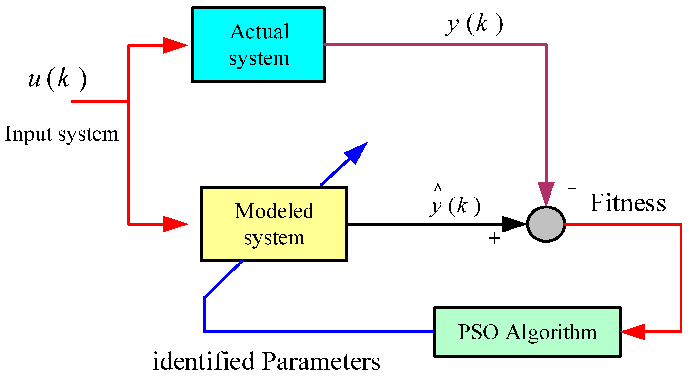
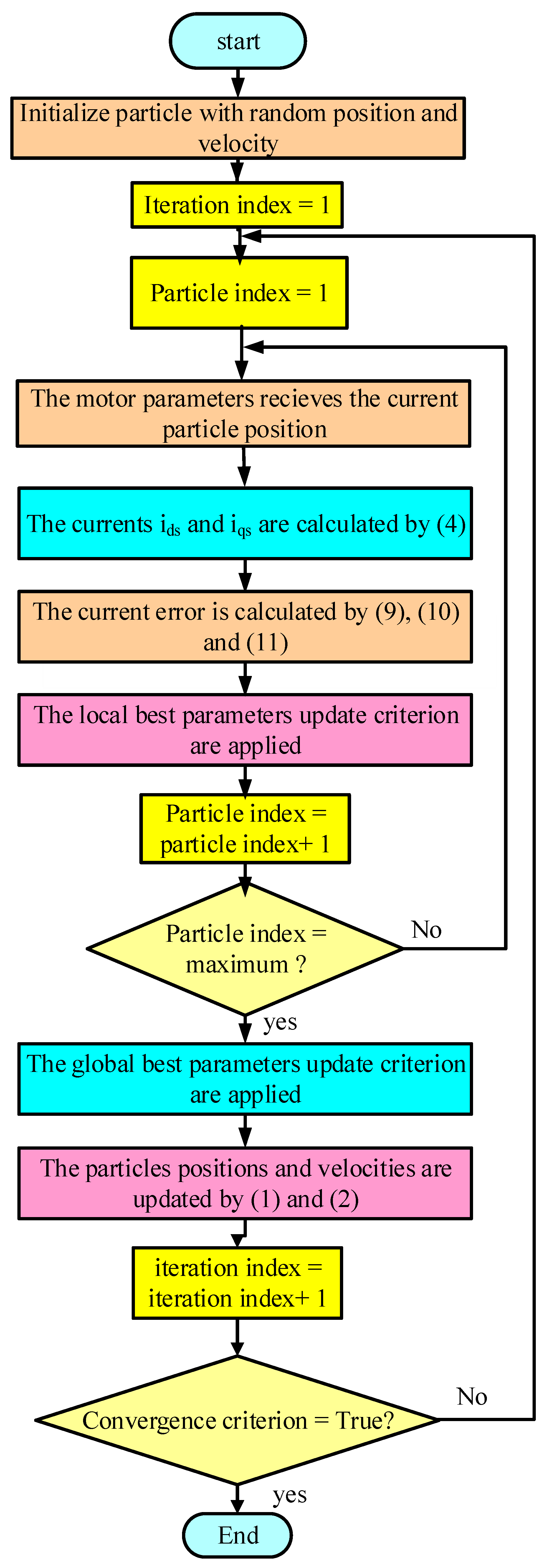
2. IM Parameter Determination Based on PSO Algorithm
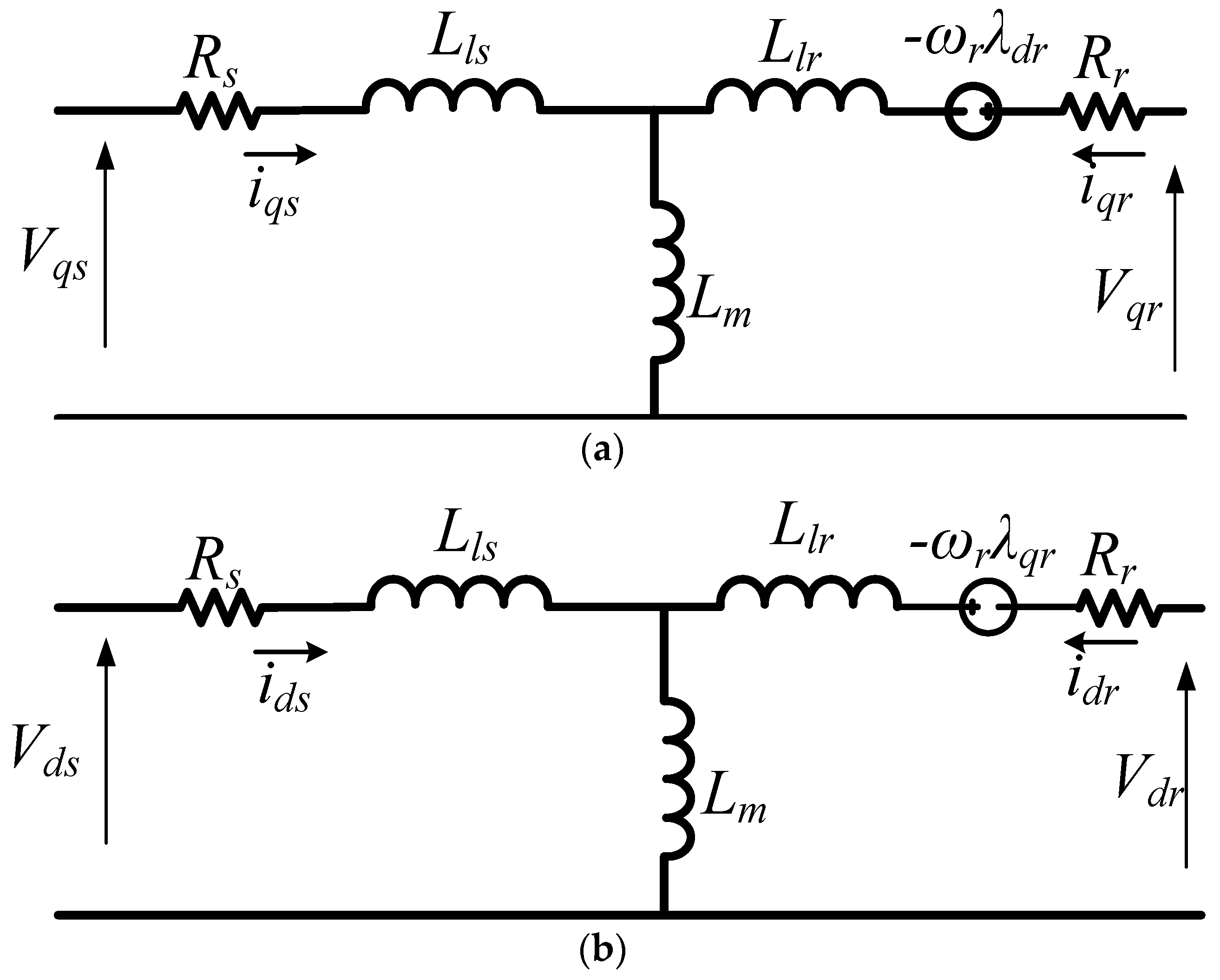
2.1. Parametric Characterization
2.2. Non-Parametric Characterization
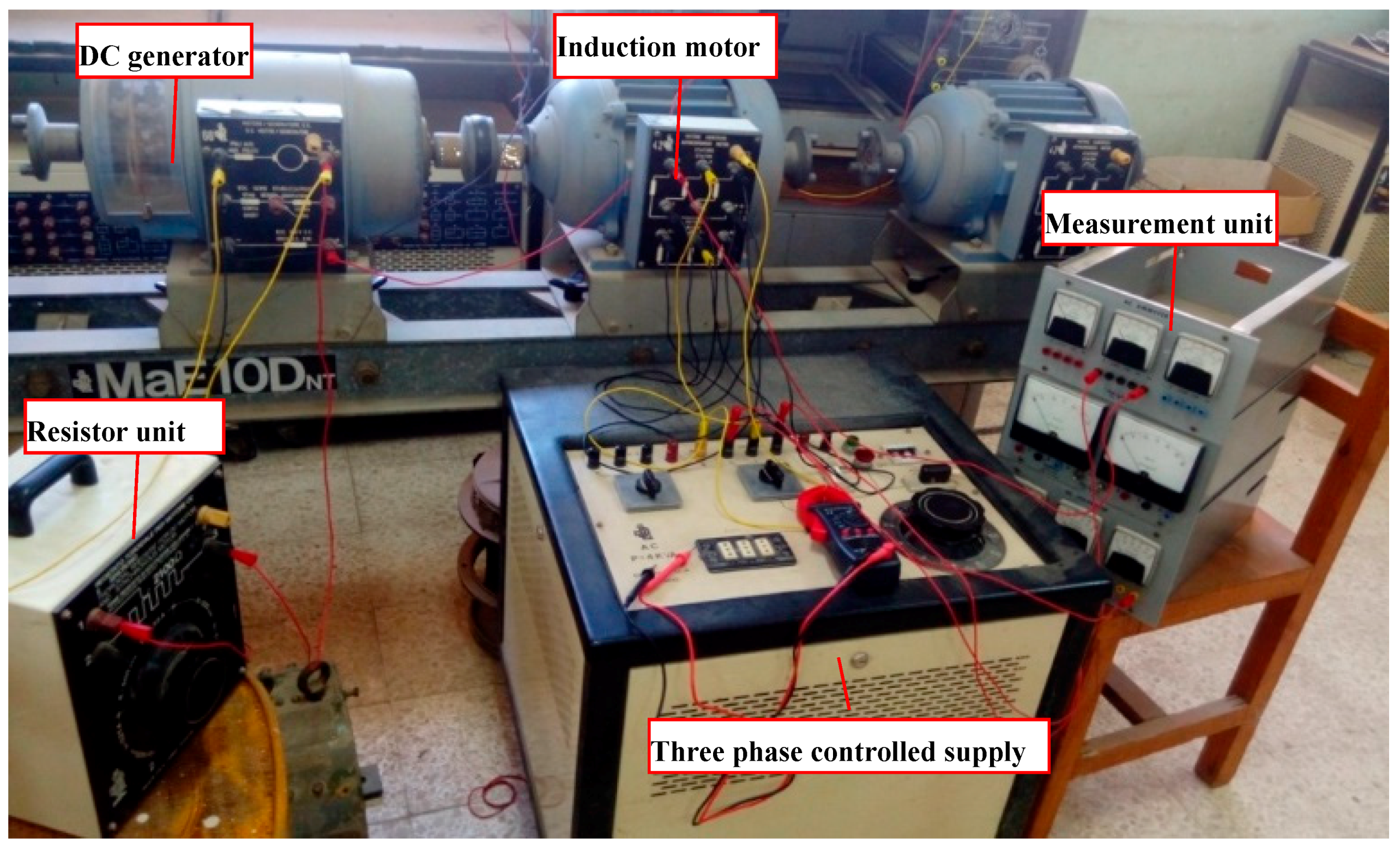
3. Results and Discussions
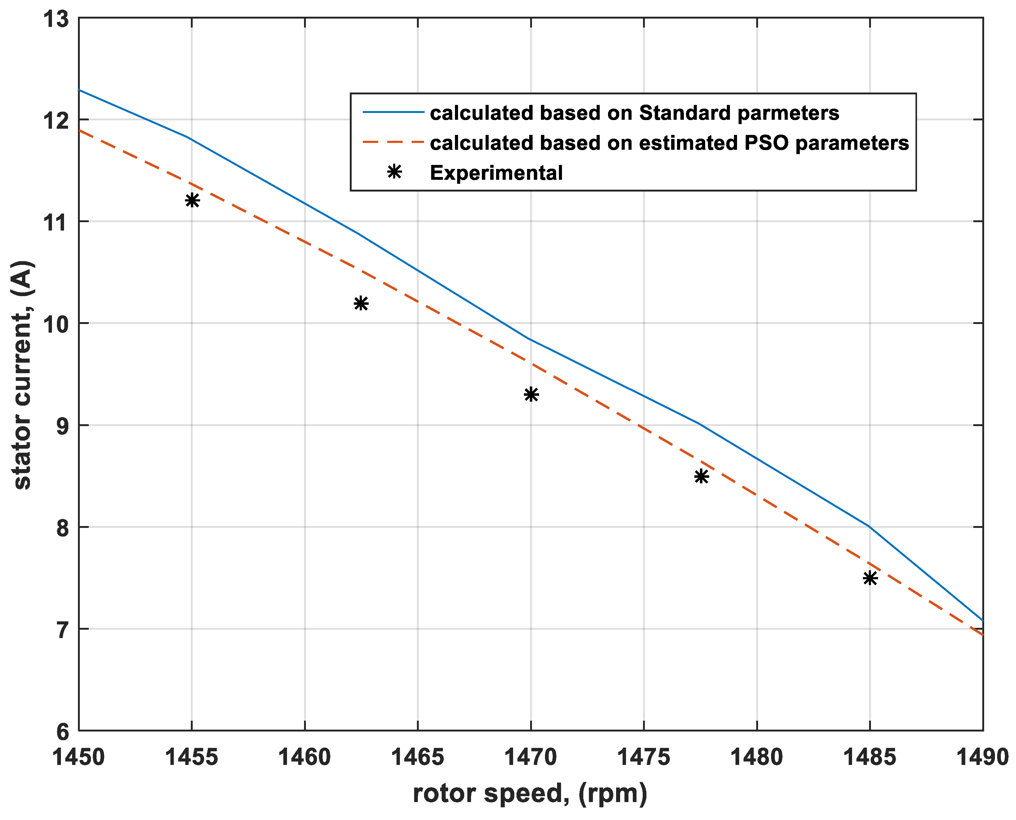
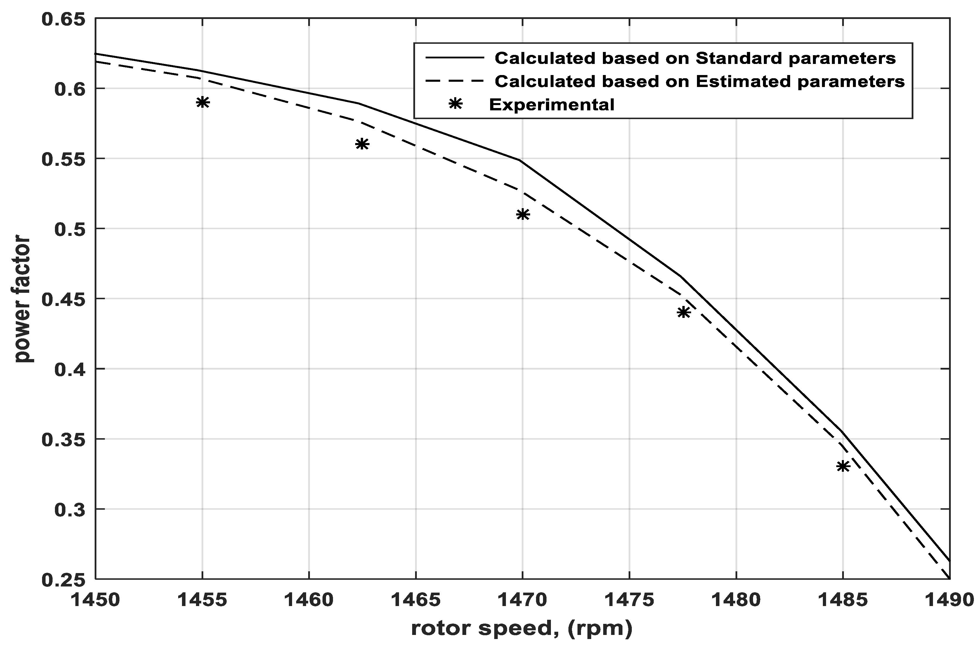
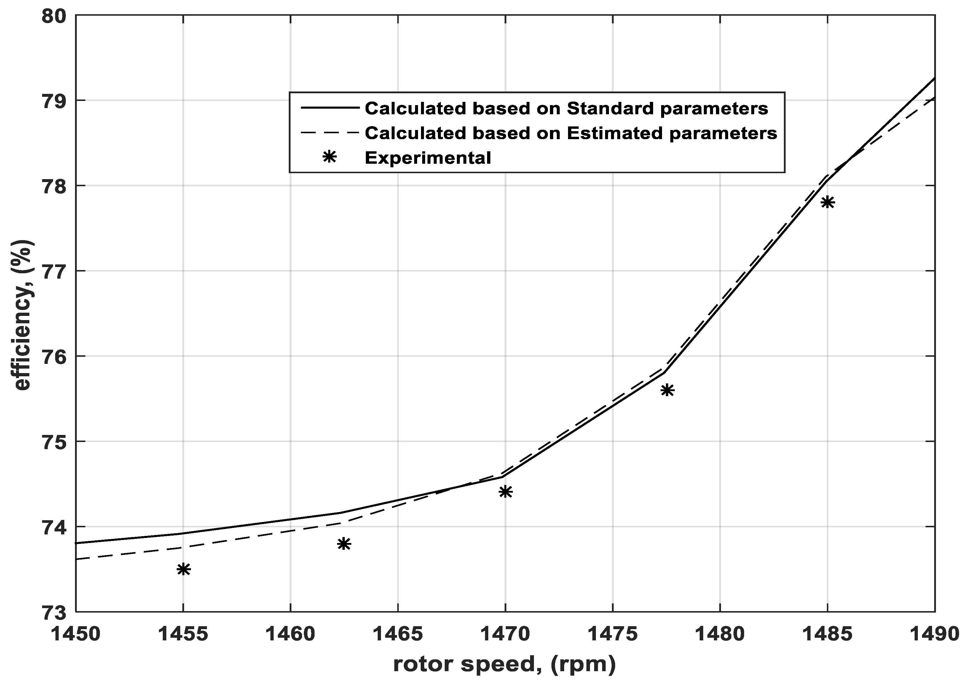
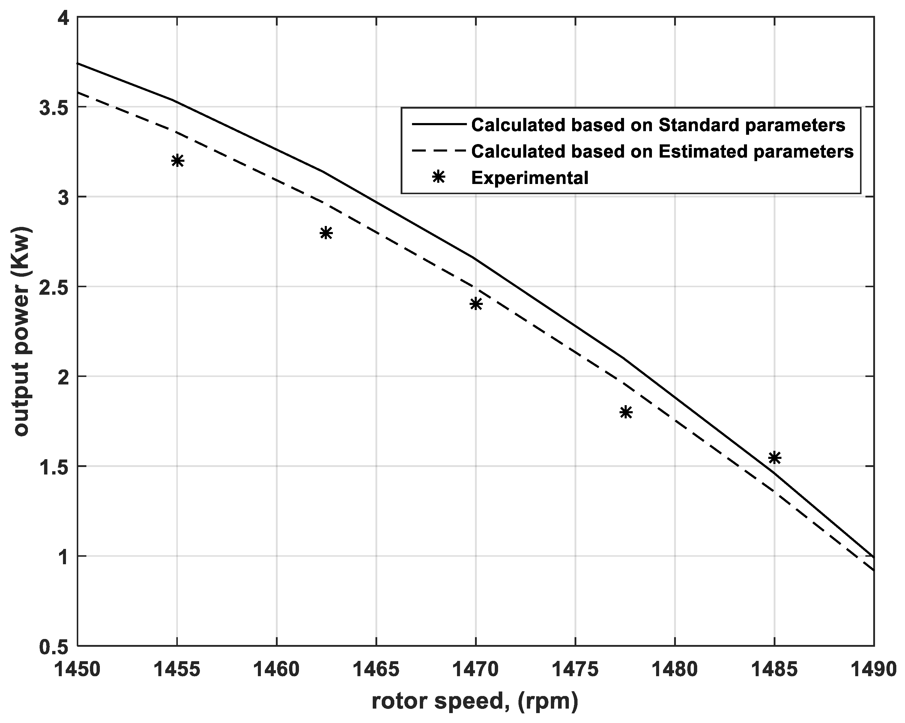
3.1. Characteristic of Induction Motor
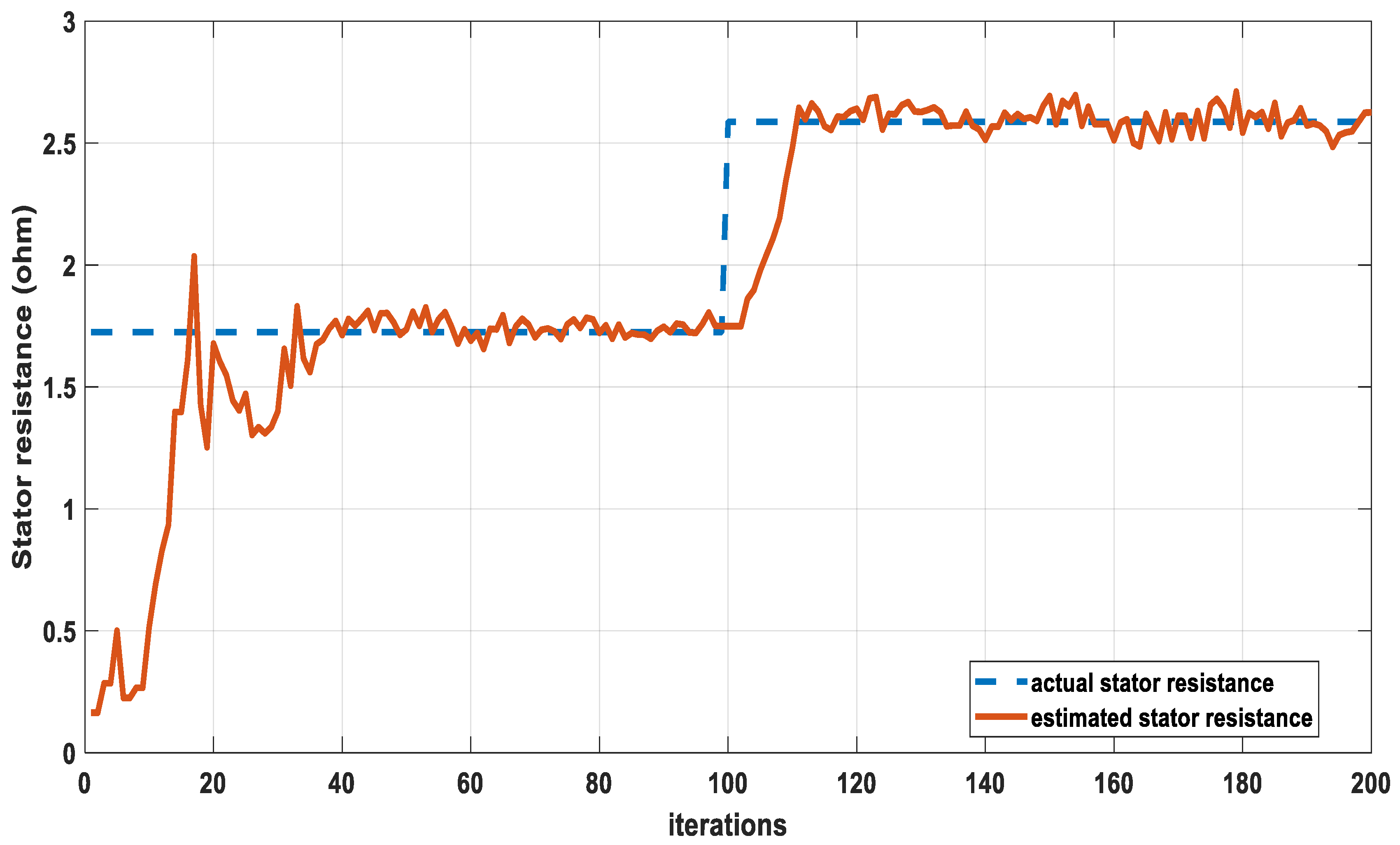
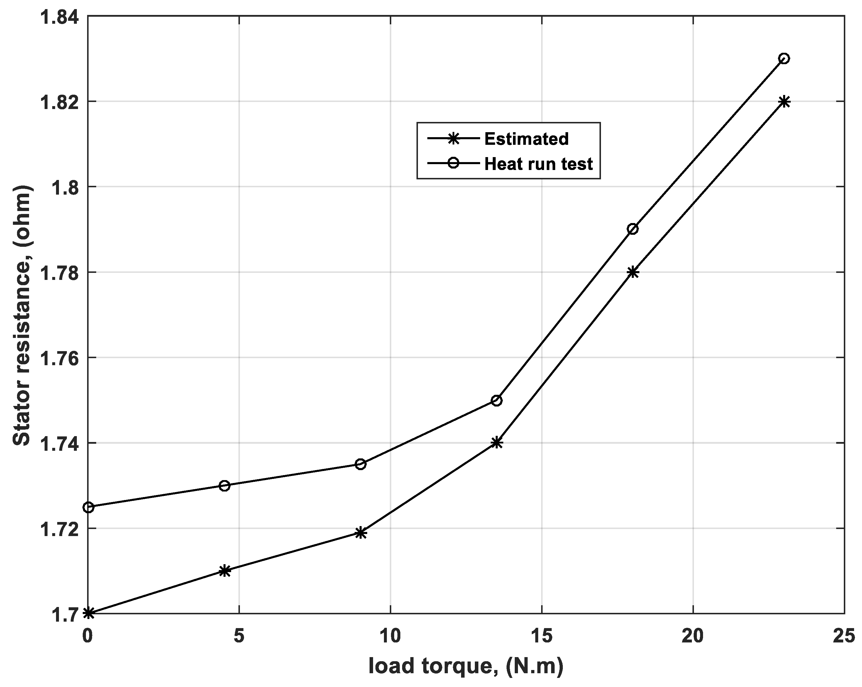
3.2. Temperature Influence on Stator Resistance
4. Conclusions
Author Contributions
Funding
Conflicts of Interest
Appendix A

| Power (HP) | 3.8 |
| Voltage (V) | 380 |
| Current (A) | 8 |
| Frequency (Hz) | 50 |
| Stator resistance (ohm) | 1.725 |
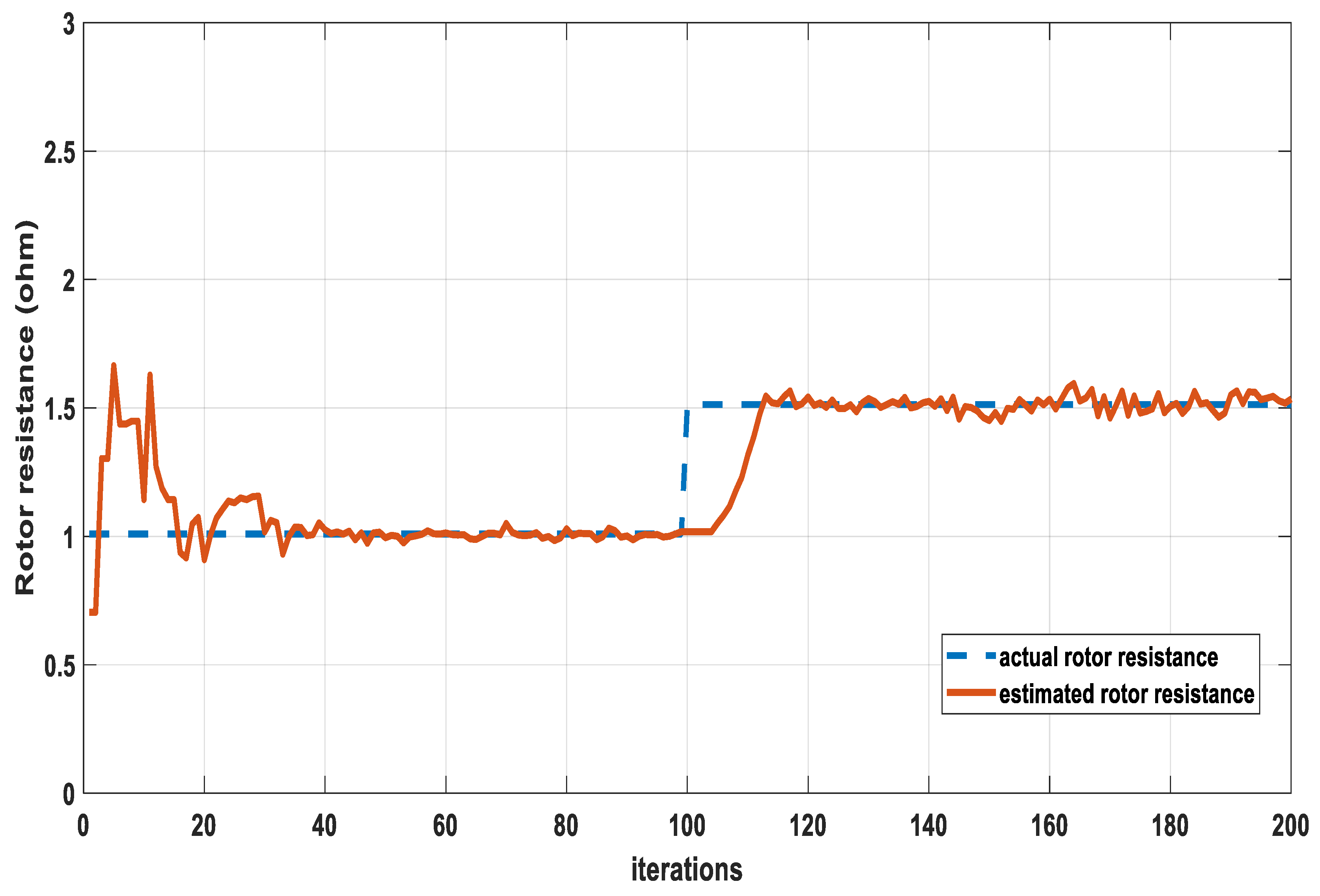
| Rotor Resistance (ohm) | 1.009 |
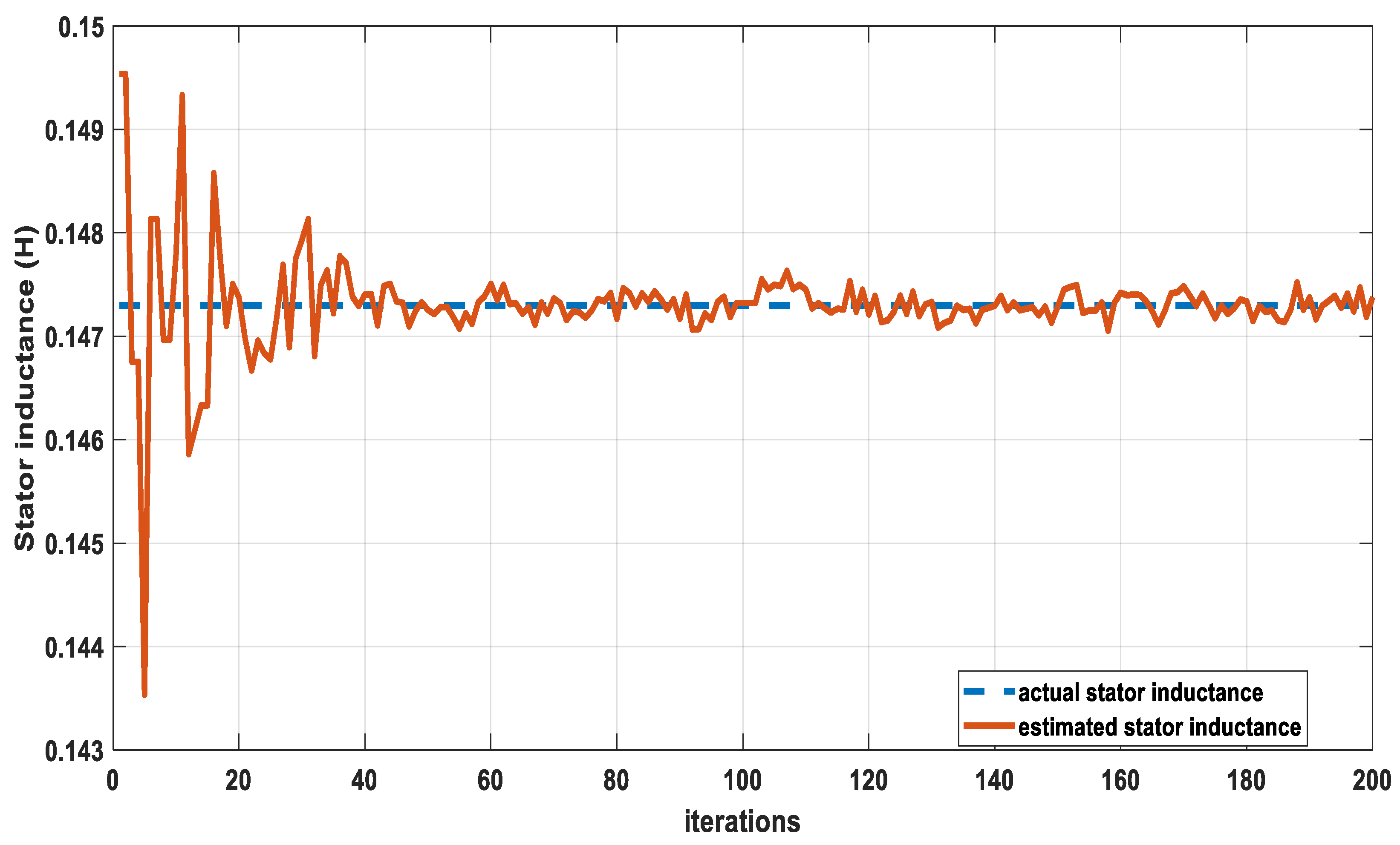
| Stator inductance (H) | 0.1473 |
| Rotor inductance (H) | 0.1473 |
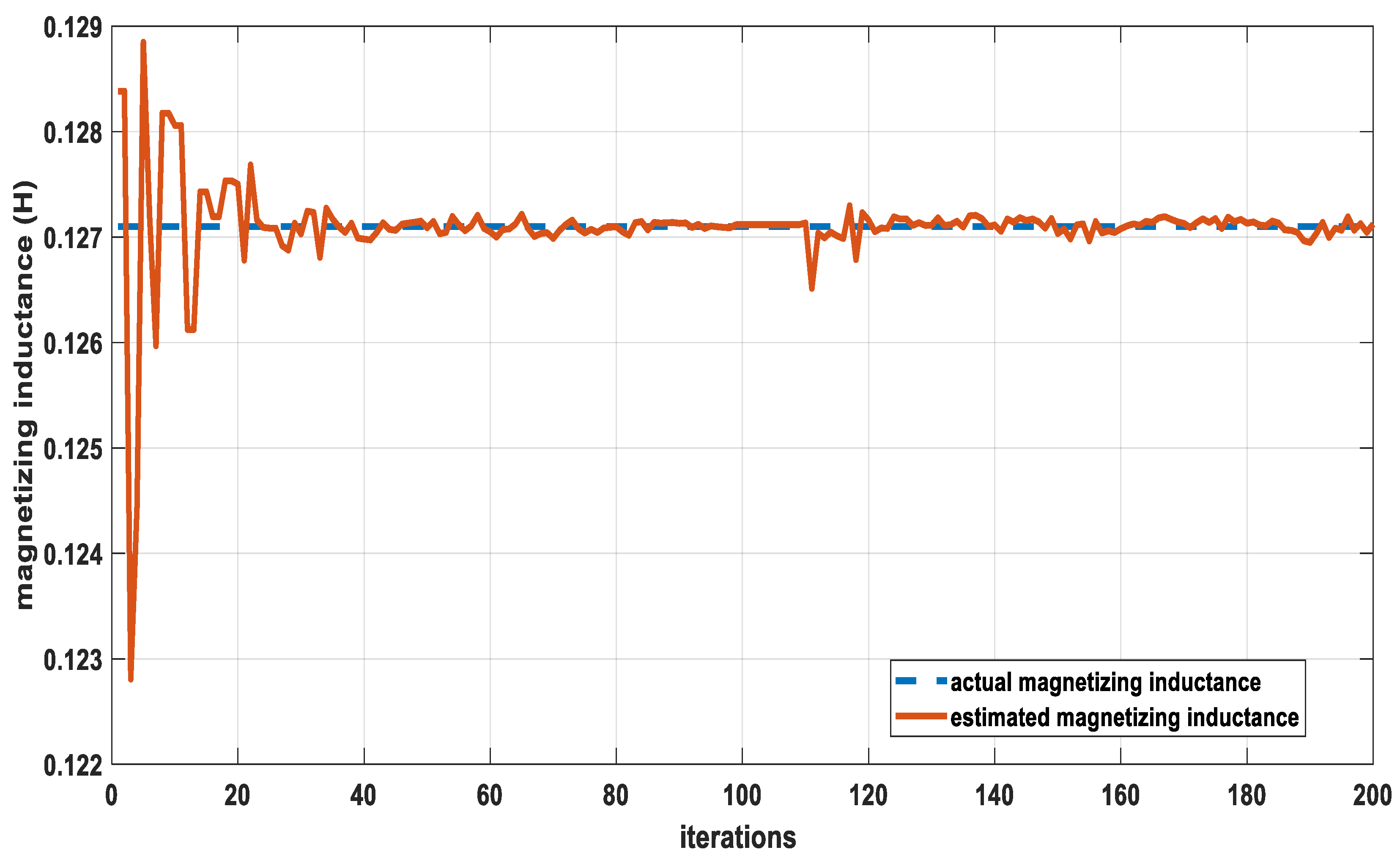
| Magnetizing inductance (H) | 0.1271 |
| Rotor speed (rpm) | 1450 |
References
- Sarhan, H. Efficiency optimization of vector controlled induction motor drive. IJAET 2014, 7, 666–674. [Google Scholar]
- Guimarães, J.M.C.; Bernardes, J.V.; Hermeto, A.E.; Bortoni, E.C. Determination of three-phase induction motors model parameters from catalog information. In Proceedings of the 2014 IEEE PES General Meeting/Conference & Exposition, National Harbor, MD, USA, 27–31 July 2014; pp. 1–5. [Google Scholar]
- Córcoles, F.; Pedra, J.; Salichs, M.; Sainz, L. Analysis of the induction machine parameter identification. IEEE Trans. Energy Convers. 2002, 17, 183–190. [Google Scholar] [CrossRef]
- Wengerkievicz, C.A.; Elias, R.A.; Batistela, N.J.; Sadowski, N.; Kuo-Peng, P.; Lima, S.C.; Silva, P.A.D., Jr.; Beltrame, A.Y. Estimation of Three-Phase Induction Motor Equivalent Circuit Parameters from Manufacturer Catalog Data. J. Microw. Optoelectron. Electromagn. Appl. (JMOe) 2017, 16, 90–107. [Google Scholar] [CrossRef]
- Mohamed, M.A.; Diab, A.A.Z.; Rezk, H. Partial shading shading mitigation of PV systems via different meta -heuristic techniques. Renew. Energy 2019, 130, 1159–1175. [Google Scholar] [CrossRef]
- Al-Dhaifallah, M.; Nassef, A.M.; Rezk, H.; Nisar, K.S. Optimal parameter design of fractional order control based INC-MPPT for PV system. Sol. Energy 2018, 159, 650–664. [Google Scholar] [CrossRef]
- Fathy, A.; Rezk, H. Multi-verse optimizer for identifying the optimal parameters of PEMFC model. Energy 2018, 143, 634–644. [Google Scholar] [CrossRef]
- Abdalla, O.; Rezk, H.; Ahmed, E.M. Wind driven optimization algorithm based global MPPT for PV system under non-uniform solar irradiance. Sol. Energy 2019, 180, 429–444. [Google Scholar] [CrossRef]
- Tofighi, E.M.; Mahdizadeh, A.; Feyzi, M.R. Online estimation of induction motor parameters using a modified particle swarm optimization technique. In Proceedings of the IECON Proceeding Industrial Electronics Conference, Vienna, Austria, 10–13 November 2013; pp. 3645–3650. [Google Scholar]
- Laroche, E.; Sedda, E.; Durieu, C. Methodological insights for online estimation of induction motor parameters. IEEE Trans. Control. Syst. Technol. 2008, 16, 1021–1028. [Google Scholar] [CrossRef]
- Proca, A.B.; Keyhani, A. Sliding-mode flux observer with online rotor parameter estimation for induction motors. IEEE Trans. Ind. Electron. 2007, 54, 716–723. [Google Scholar] [CrossRef]
- Salmasi, F.R.; Najafabadi, T.A. An Adaptive Observer With Online Rotor and Stator Resistance Estimation for Induction Motors With One Phase Current Sensor. IEEE Trans. Energy Convers. 2011, 26, 959–966. [Google Scholar] [CrossRef]
- Bishop, R.R.; Richards, G.G. Identifying induction machine parameters using a genetic optimization algorithm. In Proceedings of the Southeastcon’90, New Orleans, LA, USA, 1–4 April 1990; IEEE: Piscataway, NJ, USA, 1990; pp. 476–479. [Google Scholar]
- Pillay, P.; Nolan, R.; Haque, T. Application of genetic algorithms to motor parameter determination for transient torque calculations. IEEE Trans. Ind. Appl. 1997, 33, 1273–1282. [Google Scholar] [CrossRef]
- Nangsue, P.; Pillay, P.; Conry, S.E. Evolutionary algorithms for induction motor parameter determination. IEEE Trans. Energy Convers. 1999, 14, 447–453. [Google Scholar] [CrossRef]
- Alonge, F.; D’Ippolito, F.; Ferrante, G.; Raimondi, F. Parameter identification of induction motor model using genetic algorithms. IEE Proc. Control Theory Appl. 1998, 145, 587–593. [Google Scholar] [CrossRef]
- Nolan, R.; Pillay, P.; Haque, T. Application of genetic algorithms to motor parameter determination. In Proceedings of the Conference Record-IEEE Industry Applications Society Annual Meeting, Denver, CO, USA, 2–5 October 1994; IEEE: Piscataway, NJ, USA; p. 47. [Google Scholar]
- Nikranajbar, A.; Ebrahimi, M.; Wood, A. Parameter identification of a cage induction motor using particle swarm optimization. Proc. Inst. Mech. Eng. Part I J. Syst. Control Eng. 2010, 224, 479–491. [Google Scholar] [CrossRef]
- Sahu, H.K. Two Phasing Method for Conducting Heat Run Test of Three Phase Induction Motors. In Proceedings of the International Conference on Advances in Electrical and Electronics (AEE 2010), Kerala, India, 21–22 December 2010. [Google Scholar]
- Rezk, H.; Fathy, A. Simulation of global MPPT based on teaching–learning-based optimization technique for partially shaded PV system. Electr. Eng. J. 2017, 99, 847–859. [Google Scholar] [CrossRef]
- Ibrahim, M.N.; Rezk, H.; Al-Dhaifallah, M.; Sergeant, P. Solar array fed synchronous reluctance motor driven water pump: An improved performance under partial shading conditions. IEEE Access 2019, 7, 77100–77115. [Google Scholar] [CrossRef]
- Ibrahim, M.N.; Sergeant, P.; Rashad, E.M. Relevance of Including Saturation and Position Dependence in the Inductances for Accurate Dynamic Modeling and Control of SynRMs. IEEE Trans. Ind. Appl. 2017, 53, 151–160. [Google Scholar] [CrossRef]
- Ibrahim, M.N.; Abdel-khalik, A.S.; Rashad, E.M.; Sergeant, P. An improved torque density synchronous reluctance machine with a combined star-delta winding layout. IEEE Trans. Energy Convers. 2018, 33, 1015–1024. [Google Scholar] [CrossRef]
- Li, N.-J.; Wang, W.-J.; Hsu, C.-C.J.; Chang, W.; Chou, H.-G.; Chang, J.-W. Enhanced particle swarm optimizer incorporating a weighted particle. Neurocomputing 2014, 124, 218–227. [Google Scholar] [CrossRef]
- Elghany, A.A.; Rezk, H.; el Sayed, A.H.M. Robust parameter estimation of vector controlled induction motors based on a modified particle swarm optimization technique. In Proceedings of the 2016 Eighteenth International Middle East Power Systems Conference (MEPCON), Cario, Egypt, 27–29 December 2016; pp. 171–178. [Google Scholar]
| Electrical Parameter | Rs (Ω) | Rr (Ω) | Llr = Lls (H) | Lm (H) |
|---|---|---|---|---|
| Standard | 1.725 | 1.009 | 0.0202 | 0.1271 |
| PSO | 1.7290 | 0.9322 | 0.0205 | 0.1271 |
| Error|%| | 0.232 | 7.6115 | 1.4851 | ~0 |
© 2019 by the authors. Licensee MDPI, Basel, Switzerland. This article is an open access article distributed under the terms and conditions of the Creative Commons Attribution (CC BY) license (http://creativecommons.org/licenses/by/4.0/).
Share and Cite
Rezk, H.; Elghany, A.A.; Al-Dhaifallah, M.; El Sayed, A.H.M.; Ibrahim, M.N. Numerical Estimation and Experimental Verification of Optimal Parameter Identification Based on Modern Optimization of a Three Phase Induction Motor. Mathematics 2019, 7, 1135. https://doi.org/10.3390/math7121135
Rezk H, Elghany AA, Al-Dhaifallah M, El Sayed AHM, Ibrahim MN. Numerical Estimation and Experimental Verification of Optimal Parameter Identification Based on Modern Optimization of a Three Phase Induction Motor. Mathematics. 2019; 7(12):1135. https://doi.org/10.3390/math7121135
Chicago/Turabian StyleRezk, Hegazy, Asmaa A. Elghany, Mujahed Al-Dhaifallah, Abo Hashema M. El Sayed, and Mohamed N. Ibrahim. 2019. "Numerical Estimation and Experimental Verification of Optimal Parameter Identification Based on Modern Optimization of a Three Phase Induction Motor" Mathematics 7, no. 12: 1135. https://doi.org/10.3390/math7121135
APA StyleRezk, H., Elghany, A. A., Al-Dhaifallah, M., El Sayed, A. H. M., & Ibrahim, M. N. (2019). Numerical Estimation and Experimental Verification of Optimal Parameter Identification Based on Modern Optimization of a Three Phase Induction Motor. Mathematics, 7(12), 1135. https://doi.org/10.3390/math7121135