Article

Research on the Design and Meshing Performance Analysis of Face Gear Face Gear Meshing Nutation Reducers

School of Mechanical Engineering and Automation, Fuzhou University, Fuzhou 350108, China
*
Author to whom correspondence should be addressed.
Mathematics 2025, 13(3), 476; https://doi.org/10.3390/math13030476
Submission received: 6 December 2024 / Revised: 15 January 2025 / Accepted: 16 January 2025 / Published: 31 January 2025

Abstract

:
In view of the problems of the complex design, difficult machining, and high manufacturing cost of a traditional nutation reducer, this paper intends to design a nutation reducer and study its meshing performance. First, the meshing pair is designed by the method of internal and external cutting of the shaper cutter, and the method of face gear tooth surface modification is proposed. Second, based on tooth contact analysis (TCA) and loaded tooth contact analysis (LTCA), the contact performance of the meshing pair is studied. Then, the nutation reducer is improved by using the pair instead of the internal bevel gear pair. Finally, examples are presented to test the feasibility of the improved design. The results show that the improved nutation reducer maintains the advantages of a large transmission ratio and high bearing capacity of the traditional nutation reducer and can make use of the advantages of face gears to further improve its transmission performance. This study can lay a foundation for the further application and popularization of nutation reducers.

1. Introduction

A reducer is an intermediate device connecting a power source and an actuator, and its development has a history hundreds of years long. With the continuous progress of modern technology, especially the rapid development of new energy vehicles and other equipment, the requirements for reducers are increasing day by day. Nowadays, reducers are more inclined to be lightweight, miniaturized, and precise. In this context, nutation reducers with the advantages of a compact structure, small size, and light weight have received extensive attention in the industrial field [1,2,3,4] and have gradually become a hotspot for research and application.
In the past few decades, many scholars have conducted a lot of research on nutation reducers. Yamamori Motoyasu [5] analyzed the nutation transmission mechanism and studied a nutating gear transmission mechanism suitable for automobile devices. Cheng et al. [6] analyzed the transmission ratio calculation formula of several nutation gear transmission types through practical research and proposed two output mechanism schemes. Yu et al. [7] applied nutation drives to gear drives, analyzed the calculation method of torque in cone difference nutation drives, and proposed a new optimization method. Wang et al. [8] proposed a nutation reduction transmission device, and carried out three-dimensional modeling and motion simulation to verify the correctness of the mechanism. Yao et al. [9] applied nutation drives to a nutation reducer with double-sided spiral bevel gears, established a three-dimensional model of the reducer, and carried out simulation analysis. Cai et al. [10] completed the kinematic analysis of an internal bevel gear nutation drive by combining gear meshing principles. Mathur et al. [11] calculated the meshing stiffness of nutation drives and analyzed the elastohydrodynamic lubrication of gears. Saribay et al. [12] proposed a peripheral ring transmission (PMT), studied its contact stress and bending stress, and applied it to the reducer of a helicopter, combining this with structural principles to analyze the changes in gear load and bearing load and analyze the meshing efficiency of the PMT system through the theory of elastohydrodynamic lubrication. The analysis was carried out, and a formula for calculating the meshing efficiency was obtained. The above research deepens the understanding of nutation transmission mechanisms and promotes the practical application and development of nutation deceleration technology.
A nutation reducer has a simple structure and a high reduction ratio. As the core component of the nutating reducer, the meshing bevel gear pair has attracted some scholars to conduct research on its design methods, processing, and manufacturing [13]. Shih et al. [14,15] proposed a unified mathematical model to simulate the end-face-hobbing and end milling processes of a general hypoid gear generator, and studied the relief deviation of the design parameters, including tool parameters, machine tool settings, and auxiliary gears using the polynomial coefficients of surface correction motion. Simon [16,17] used a multi-objective optimization method to propose the optimal tool geometry and machine tool settings, and introduced the optimal tooth profile modification into the teeth of a face-hobbing quasi-hyperbolic gear, with the purpose of reducing tooth contact pressure and transmission errors and reducing the sensitivity of the gear pair to tooth surface errors and the relative positions of mating components. Deng et al. [18] proposed a spiral bevel gear pair using the face-milling method, which can improve the cutting strip width and processing efficiency, and verified the feasibility of this method through processing experiments and measurements of spiral bevel gear pairs. Tang et al. [19] proposed a double-arc tooth logarithmic spiral bevel gear pair (DCAP) with a higher contact/bending strength, better load distribution, and smaller transmission error, and studied four of them. The influence of this typical manufacturing error on the meshing characteristics of bevel gear pairs provides a basic reference for the tolerance design of cycloidal bevel gears. However, there are a limited amount of research results on internal-meshing bevel gear pairs and nutation reducers that utilize internal-meshing bevel gear pairs. The main reasons are as follows: (1) the design of the teeth of the internal bevel gear pair is complex, the machining means are scarce, and the manufacturing cost is high; and (2) there are relatively few application fields for internal bevel gear transmission, and researchers lack the internal driving force for exploration. Nutation reducers have few parts, a simple structure, and a high load. Under the background of the ultimate pursuit of the high load and high speed of reducers for manufacturing equipment in various fields, nutation reducers have unique advantages that other types of reducers do not have. To promote the application of nutation reducers in more fields, further improvements are necessary.
Face gear transmission [20,21,22] is a kind of transmission mode which can realize space interleaving. Figure 1 shows three typical face gear pairs with different shaft angles. The diversity of shaft angles allows the face gears to adapt to a wider range of transmission scenarios. At present, face gear transmission has been matured and applied to the main reducer of armed helicopters [23], and its good meshing performance has attracted extensive attention from researchers. Litvin et al. [24] made a thorough study of the tooth engagement of the face gear and derived the conditions for the tooth root undercut and tooth tip sharpening of the face gears. Zanzi et al. [25] analyzed the face gear by finite element simulation method, and studied its meshing performance deeply, so as to make theoretical preparation for the design and application of face gear. Zhang et al. [26] established the design criteria of offset face gears, the axis of the pinion and the face gear are staggered. Liu et al. [27] proposed an offset face gear and multiple pinion gear transmission, which greatly utilized the advantages of offset face gear. Kawasaki et al. [28] studied helical gears, and obtained the reasonable design parameters. Feng et al. [29] analyzed the involute helical end face gear transmission. Zhu et al. [30] established a torsion-bending-pendulum gear transmission model with multi-state meshing and analyzed its dynamics. Zschippang et al. [31] studied the general generation method of face gears with helix angle, shaft angle and axial offset, and geometrically modified the pinion tooth profile. Peng et al. [32] studied the method of surface-active modification of face gear and reduced the vibration of face gear transmission through modification, which provided theoretical basis for vibration reduction design of face gear pair. Hochrein et al. [33] proposed two methods for calculating the contact stress of face gear drives with arbitrary configurations of helix angles and center offsets, as there are no established calculation standards for face gear transmissions. It can be found from the above documents that domestic and foreign research institutions invest a lot of manpower and material resources to make the design theory and manufacturing method of face gear transmission mature day by day.
Compared to the meshing bevel gear transmission, the face gear transmission has a simple tooth surface design, low error sensitivity, and the face gear can be processed with a gear shaping cutter, which is easy to process and the technology is mature. Therefore, to promote the application of nutation reducers, this paper aims to replace the internal meshing bevel gear pair with a face gear face gear meshing pair for improving the nutation reducer. The specific contents are as follows: In Section 2, a mathematical model for the conjugate meshing of face gear face gear pairs is derived using the method of internal and external cutting of the shaper cutter, and the meshing performance improvement method based on face gear tooth surface modification is proposed. In Section 3, based on TCA and LTCA, the geometric contact performance and load contact performance of face gear meshing pair are further studied to verify the meshing correctness of face gear meshing pair. In Section 4, the improved design of nutation reducer is carried out by replacing the internal meshing bevel gear meshing pair of traditional nutation reducer with the proposed face gear meshing pair. Section 6 summarizes the main conclusions of this study.

2. Geometric Generation and Modification Design of Nutation Face Gear Tooth

2.1. Design of Shaper Cutter

The tooth profile of the shaper cutter used for machining the face gear blank is the general involute tooth profile, and the tooth shape of the cutter is shown in Figure 2. The plane X0 = 0 denotes the symmetrical plane of the tooth groove of the shaper cutter, and the other side tooth surface can be obtained according to the symmetry. θs0 is used to determine the shaper cutter on the base circle of the groove width of half. θs0 denotes the angle from the symmetry line of the cutter slot to the starting point of the involute tooth profile.
The gear shaper cutter satisfies standard involute gear equation such as Equation (1).
θ s 0 = π 2 Z s i n v α s
where, invαs denotes the involute function of the shaper cutter; Zs denotes the number of teeth of the shaper cutter, and αs denotes the pressure angle of the shaper cutter.
θ s = θ k + α k s = tan α k s
where, θs denotes the angle between the starting point of the involute of the shaper cutter and any point of the involute; θk denotes the spread angle of any point of the involute of the shaper cutter; αks denotes the pressure angle of any point of the involute of the shaper cutter.
According to Figure 2, the position vector of the gear shaper profile is Equation (3).
r s u s , θ s = x s y s z s 1 = r b s [ sin ( θ s 0 + θ s ) θ s cos ( θ s 0 + θ s ) ] r b s [ sin ( θ s 0 + θ s ) θ s cos ( θ s 0 + θ s ) ] u s 1
where, rbs represents the base circle radius of the shaper cutter, μs represents the variable in the axial direction of the shaper cutter.
Unit normal vector of shaper cutter is Equation (4).
n s = r s θ × r s u r s θ × r s u = cos ( θ s + θ s 0 ) sin ( θ s + θ s 0 ) 0

2.2. Generation of Face Gear with Internal and External Meshing

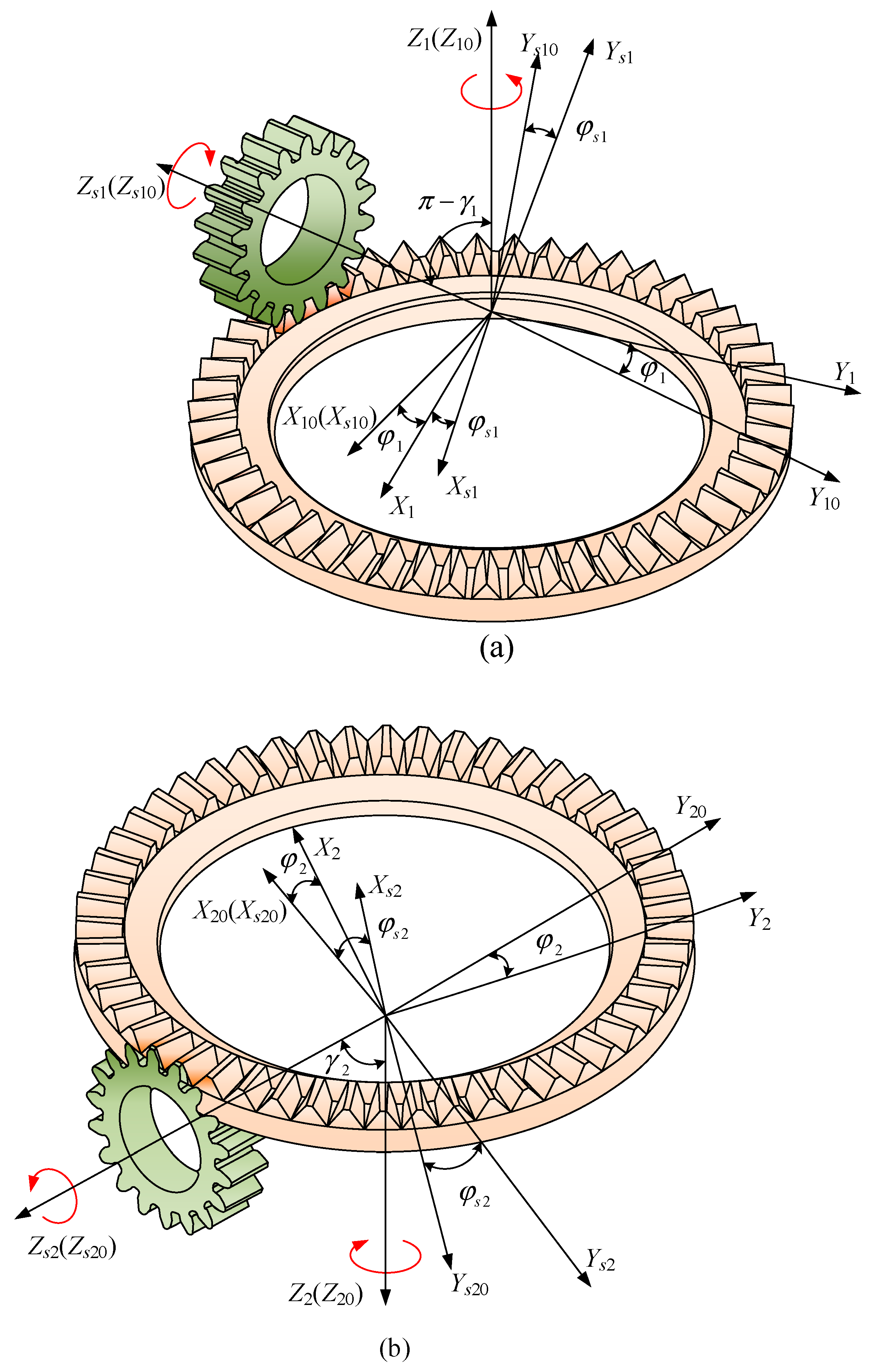
Figure 3 shows face gear with internal and external cut surfaces machined using the internal and external cut method using a shaper cutter. Figure 3a represents the coordinate system for machining external meshing face gear. S10(O10-X10Y10Z10) is fixed coordinate system, Z10 coincides with the rotation axis of the external meshing face gear, S1(O1-X1Y1Z1) is connected to the face gear with external meshing, Ss10(Os10-Xs10Ys10Zs10) is fixed coordinate system, Zs10 coincides with the rotation axis of cutter 1, Ss1(Os1-Xs1Ys1Zs1) is connected to the cutter 1. The origins of the four coordinate systems coincide, Z10 and Z1 coincide, Xs10 and X10 coincide, Zs1 and Zs10 coincide. Z10 and Zs10 included angle of π-γ1, φs1 denotes the instantaneous rotation angle of cutter 1, φ1 denotes the instantaneous rotation angle of the external meshing face gear.
Figure 3b represents the coordinate system for machining internal meshing face gear. S20(O20-X20Y20Z20) is fixed coordinate system, Z20 coincides with the rotation axis of the internal meshing face gear, S2(O2-X2Y2Z2) is connected to the face gear with internal meshing, Ss20(Os20-Xs20Ys20Zs20) is fixed coordinate system, Zs20 coincides with the rotation axis of cutter 2, Ss2(Os2-Xs2Ys2Zs2) is connected to the cutter 2. The origins of the three coordinate systems coincide, Z20 and Z2 coincide, Xs20 and X20 coincide, Zs2 and Zs20 coincide. Z20 and Zs20 included angle of γ2, φs2 denotes the instantaneous rotation angle of cutter 2, φ2 denotes the instantaneous rotation angle of the internal meshing face gear.
According to the principle of gear meshing, the meshing conditions of the two gear tooth surfaces is written as Equation (5).
f u s , θ s , φ s = n s ( s ) · v s ( sn ) = 0
where, vs(sn) is the relative velocity of shaper cutter can be determined with the Equation (6).
v s sn = ω s sn × r s + d D d t ω s × D = ω s y s n s n n z s cos φ s x s + n s n n z s sin φ s n s n n x s cos φ s n s n n y s sin φ s
Here is an example of an externally meshing gear. Substituting equations Equations (4) and (5) into Equation (6), and the meshing equation between the tool and the external meshing face gear is obtained (the same is true for the the internal meshing face gear).
f u s , θ s , φ s = r b s 1 Z s Z 1 u s Z s Z 1 sin γ 1 cos φ s + θ s + θ s 0
The transformation matrix (Appendix A) of the external meshing face gear from the coordinate system Ss1 to the coordinate system S1 can be expressed as Equation (8).
M 1 S 1 = M 110 M 10 S 10 M S 10 S 1 = cos φ 1 cos φ s 1 cos γ 1 cos φ 1 cos φ s 1 cos γ 1 sin φ 1 cos φ s 1 cos φ 1 sin φ s 1 sin γ 1 sin φ 1 0 sin φ 1 cos φ s 1 cos γ 1 cos φ 1 sin φ s 1 cos γ 1 cos φ 1 cos φ s 1 + sin φ 1 sin φ s 1 sin γ 1 cos φ 1 0 sin γ 1 sin φ s 1 sin γ 1 cos φ s 1 cos γ 1 0 0 0 0 1
Similarly, the transformation matrix of the internal meshing face gear from the coordinate system Ss2 to the coordinate system S2 can be expressed as Equation (9).
M 2 S 2 = M 220 M 20 S 20 M S 20 S 2 = cos φ 2 cos φ s 2 + cos γ 2 cos φ 2 cos φ s 2 cos γ 2 sin φ 2 cos φ s 2 cos φ 2 sin φ s 2 sin γ 2 sin φ 2 0 sin φ 2 cos φ s 2 + cos γ 2 cos φ 2 sin φ s 2 cos γ 2 cos φ 2 cos φ s 2 + sin φ 2 sin φ s 2 sin γ 2 cos φ 2 0 sin γ 2 sin φ s 2 sin γ 2 cos φ s 2 cos γ 2 0 0 0 0 1
Since the tooth surface of the face gear is formed by the tooth surface envelope of the gear shaper cutter, the expression of normal vector of face gear tooth surface established by the spatial meshing theory can be written as Equation (10).
n n ( θ s , φ s ) = L n S n · n s ( u s , θ s )
where, LnSn denotes a 3 × 3 submatrix of MnSn (n = 1, 2), same as below.
Thus, by substituting Equations (3), (8) and (9) into Equation (11), the gear tooth surface equation of the internal and external meshing face gear can be obtained.
r n ( u s , θ s , φ s ) = x n y n z n 1 = M n S n · r s ( u s , θ s )

2.3. Conjugated Conditions of Face Gear Face Gear Pair

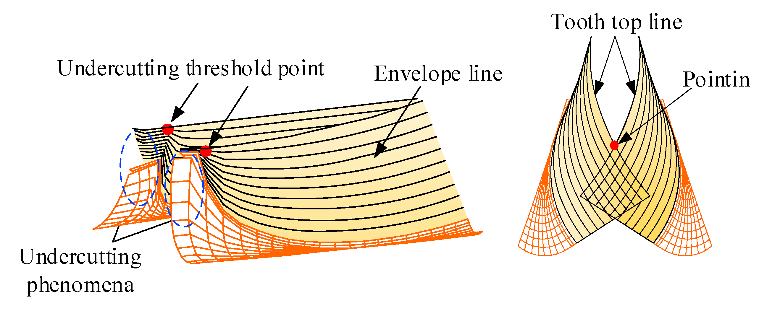
As shown in Figure 4, in actual machining, there is a limit meshing point between the gear shaper cutter and the face gear, that is, the working pressure angle cannot be equal to zero. When the working pressure angle is too small, the conjugate tooth profile of the face gear will be cut off by the transition part of the tooth tip of the gear shaper cutter, that is, the root undercut phenomenon occurs; The larger the working pressure angle, the smaller the tooth tip thickness. When the tooth tip thickness reaches a certain position, the tooth tip becomes zero, and the tooth tip becomes sharp.
At the undercut critical point on the shaper cutter and face gear tooth surface, the following relationship exists.
v s ( sn ) + v s = 0
where, νs denotes the absolute velocity of the shaper cutter, νs(sn) denotes the relative velocity of the shaper cutter at the meshing point of the face gear.
Considering that Equation (7) is an identity for all time t, differentiate it, and arrange the equations needed to determine the existence of undercut limit lines on the cutter tooth surface [34].
r s = r s ( θ s , φ s ) f ( u s , θ s , φ s ) = 0 f ( u s , θ s , φ s ) t = 0
Simplify Equation (13) to obtain.
Δ = x s u s x s θ s v x ( s n ) z s u s z s θ s v z ( s n ) f u s f θ s f φ s d φ s d t = 0
where, fμs, fθs and fφs represents partial derivatives of meshing equation with respect to μs, θs and φs, respectively, ∂xs/∂μs = 0, ∂zs/∂μs = 0, ∂xs/∂θs = 0, ∂zs/∂θs = rbsθssin(θs0 + θs).
The minimum inner radius of the face gear root without undercutting can be obtained by arranging the above equations and expressed as Equation (15).
L i n = x 2 ( θ s , φ s ) + ( y ( θ s , φ s ) sin γ + z ( θ s , φ s ) cos γ + r b s cot γ ) 2
Assuming that a cone at the tooth tip of the face gear is used to cross section the tooth surfaces on both sides of the gear, this cone surface is coaxial with the shaper cutter and tangent to the cylinder with radius rds = rpsms, where rps denotes the pitch circle radius of the gear shaper cutter and ms denotes the shaper cutter module. When rds < rbs, rds = rbs should be taken.
According to the symmetry of the tooth surfaces on both sides of the face gear teeth, the sharp tip position of the tooth tip should be on its symmetry plane, and the coordinates of the sharp point satisfy Equation (16).
x ( θ s , φ s ) = 0 y ( θ s , φ s ) cot γ + r d s sin γ + z ( θ s , φ s ) = 0
Equation (16) x(θs″,φs″) and z(θs″,φs″) are substituted into the equation Equation (7), the values of θs and φs can be calculated. Then substitute the obtained value into Equation (16) and the value of y(θs″,φs″) is obtained, then the maximum outer radius at which the tooth tip of the face gear does not become sharp is expressed as Equation (17).
L o u t = y ( θ s , φ s ) / sin γ
Conjugation of gear tooth surfaces is based on the concept of envelope. If the meshing equations of the two gears and the cutter are equal, then the two gears are conjugate. Because of the face gear face gear pair, a pair of gears that mesh with each other are formed by external cutting and internal cutting by cutters of the same parameter. Therefore, it is possible to obtain that the meshing of two gears satisfies by Equation (18).
f 1 ( u s , θ s , φ s ) = f 2 ( u s , θ s , φ s )
Simultaneous Equations (7) and (18) conjugate conditions of face gear face gear pairs can be obtained by sorting out.
θ s ( u s , φ s ) = cos 1 r b s Z s Z 2 cos γ 2 Z s Z 1 cos γ 1 u s Z s Z 2 sin γ 2 Z s Z 1 sin γ 1 ( φ s + θ s 0 )

2.4. Tooth Modification Design of Face Gear

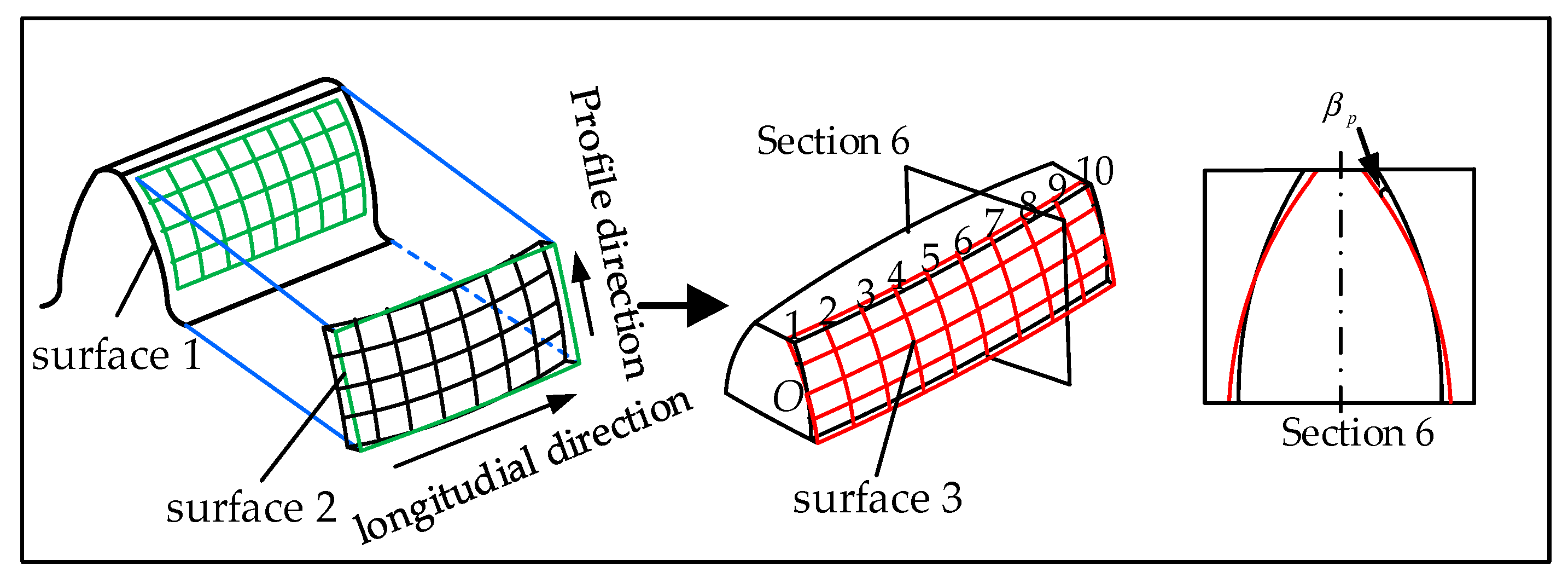
By modifying the shaper cutter and machining the face gear with the modified gear shaper cutter, the modified face gear can be obtained. The modification method described in this chapter is based on the original parabola modification, and then rotate the tooth surface by a βp to improve the tooth root strength and ensuring that there is no interference in the process of gear meshing.
As shown in Figure 5, the shaper cutter tooth surface 1 is modified into tooth surface 2. Based on previous experience, modification parabola y = apx2 is selected, modification amount Δm is calculated, and modification amount Δm is subtracted from the value of x on the coordinate of theoretical tooth surface to obtain a new abscissa x, and the values of y and z are kept unchanged.
Δ m = a p x 2
Then from the tooth surface 2 modification to the final shaper cutter tooth surface 3, the equation of gear involute in rectangular coordinate system is based on the origin of rectangular coordinate system, assuming that the coordinate value at point O coordinate is (xz,yz), Equations can be written as Equation (21).
x z 2 + y z 2 = r 2
where, r denotes the radius of the indexing circle, r = mz/2.
According to the Equation (22).
r b s 2 [ sin ( θ s 0 + θ 0 ) θ s cos ( θ s 0 + θ 0 ) ] 2 + r b s 2 [ sin ( θ s 0 + θ 0 ) θ s cos ( θ s 0 + θ 0 ) ] 2 = m z 2 2
Translate the origin of the coordinate system to point O and rotate it by angle βb
x = ( x x z ) cos β p + ( y y z ) sin β p + x z Δ m y = ( y y z ) cos β p + ( x x z ) sin β p + y z
The above can be achieved by adjusting the coordinate value (xz,yz) and rotation angle βp at point O. After the coordinate transformation, the modified face gear tooth can be obtained.

3. Geometric Contact Analysis of Face Gear Face Gear Pairs

3.1. TCA

The meshing form of the face gear face gear pair is point contact. In the process of analyzing its meshing characteristics and solving the contact stress, it is necessary to determine the contact trajectory of the face gear during the meshing process. Here, a single pair of face gear face gear meshing is taken as an example to solve and visualize the contact trajectories during the meshing of the external and internal face gears, and to study the influence of installation errors on the contact trajectory.
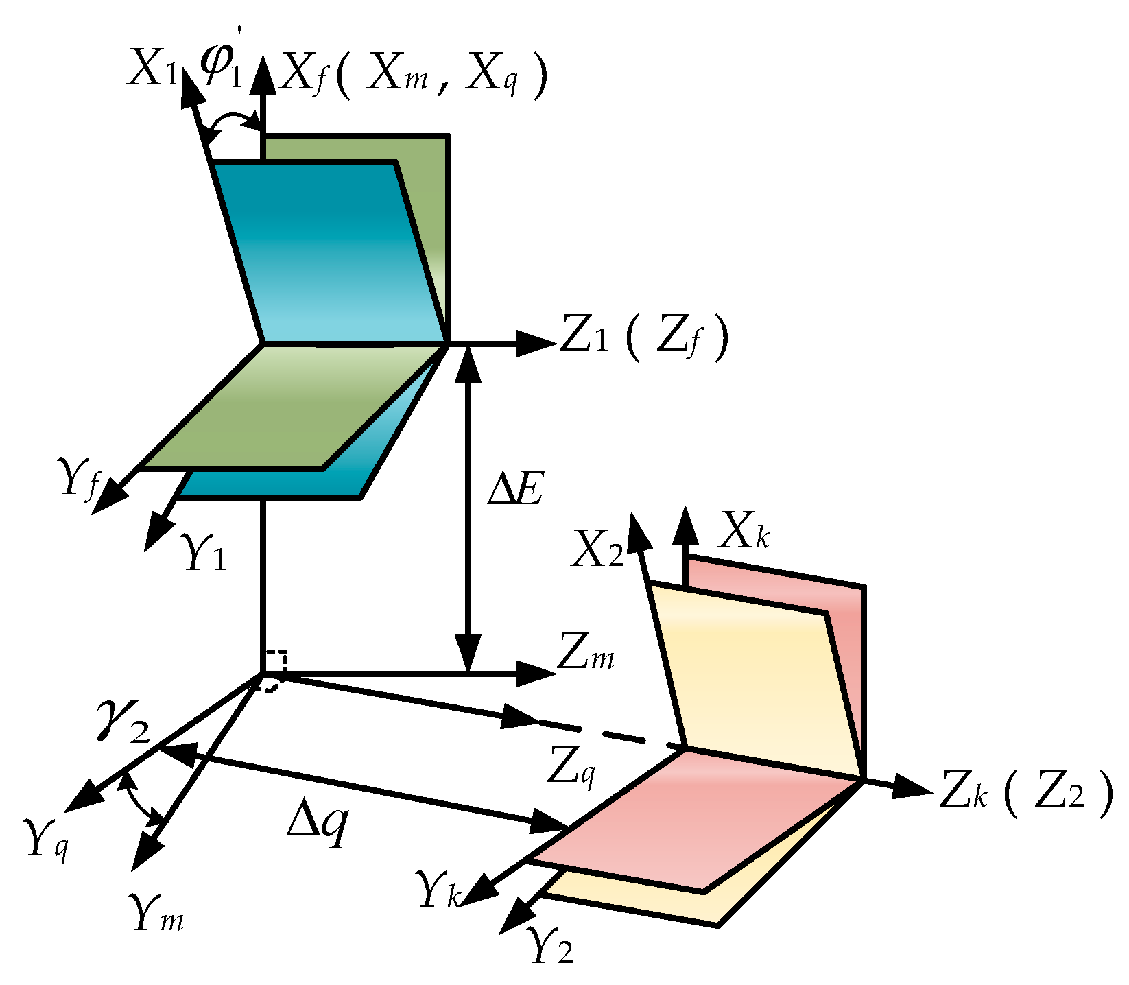
As shown in Figure 6, coordinate systems S1 and Sf are rigidly fixed to the external meshing face gear and the frame, coordinate systems S2 and Se are rigidly fixed to the internal meshing face gear and the frame, and Sq, Sm, Sk are auxiliary coordinate systems. The installation errors in the nutation drive are mainly: Nutation Angle error Δγ; offset error ΔE; Axial displacement error Δq.
Coordinate transformation is carried out on the internal and external meshing gears obtained in Section 2, and the gears are rotated to the same fixed coordinate system.
M f 1 = cos φ 1 sin φ 1 0 0 sin φ 1 cos φ 1 0 0 0 0 1 0 0 0 0 1
M f 2 = M f m M m q M q k M k 2 = cos φ 2 sin φ 2 0 Δ E cos ( γ 2 + Δ γ ) sin φ 2 cos ( γ 2 + Δ γ ) cos φ 2 sin ( γ 2 + Δ γ ) Δ q sin ( γ 2 + Δ γ ) sin ( γ 2 + Δ γ ) sin φ 2 sin ( γ 2 + Δ γ ) cos φ 2 cos ( γ 2 + Δ γ ) Δ q cos ( γ 2 + Δ γ ) 0 0 0 1
From Figure 6, the tooth surface position vector rf(1)(θs1,φs1,φ1′) and the tooth surface unit normal vector nf(1)(θs1,φs1,φ1′) of the external meshing face gear in the coordinate system can be obtained as follows:
r f ( 1 ) ( θ s 1 , φ s 1 , φ 1 ) = M f 1 r 1 ( θ s 1 , φ s 1 ) n f ( 1 ) ( θ s 1 , φ s 1 , φ 1 ) = L f 1 n 1 ( θ s 1 , φ s 1 )
where, θS1 and φS1 denote the cutter spread angle and rotation angle, respectively.
When the two face gears are engaged under installation error, in the same coordinate system Sf, the position vector and unit normal vector at the meshing contact point should always coincide, which can be determined.
x f ( 1 ) θ s 1 , φ s 1 , φ 1 = x f ( 2 ) θ s 2 , φ s 2 , φ 2 y f ( 1 ) θ s 1 , φ s 1 , φ 1 = y f ( 2 ) θ s 2 , φ s 2 , φ 2 z f ( 1 ) θ s 1 , φ s 1 , φ 1 = z f ( 2 ) θ s 2 , φ s 2 , φ 2 n x f ( 1 ) θ s 1 , φ s 1 , φ 1 = n x f ( 2 ) θ s 2 , φ s 2 , φ 2 n y f ( 1 ) θ s 1 , φ s 1 , φ 1 = n y f ( 2 ) θ s 2 , φ s 2 , φ 2 n z f ( 1 ) θ s 1 , φ s 1 , φ 1 = n z f ( 2 ) θ s 2 , φ s 2 , φ 2
Only five equations in Equation (27) are independent, so we have a system of five independent nonlinear equations with six unknowns (θs1,θs2,φs1,φs2,φ1′,φ2′). Assuming φ2′ is a known parameter, simultaneous equations can be used to find the values of the other five parameters. The contact path can be obtained by substituting them into the tooth surface equations.
Based on the above, φ1′ can be derived from φ2′, and the range of values of φ2′ is given by Equation (28).
π z 2 φ 2 π z 2
The transmission error, Δφ2′ is expressed by Equation (29).
Δ φ 2 = φ 2 N 1 N 2 φ 1 φ 1
where, φ1″ represents the value when φ2′ is 0.

3.2. LTCA

3.2.1. Calculation and Analysis of Principal Curvature and Principal Direction

According to Hertzian elastic contact theory, when calculating the contact stress and deformation of two arbitrarily shaped surfaces, it is essential to know the principal curvature of the surfaces at the contact point.
The position vector p of the surface can be represented by the variables μ, θ.
r u , θ = x u , θ i + y u , θ j + z u , θ k
where, i, j, and k are the unit vector of the surface in the coordinate system.
Assume the vector function of a regular surface is r(u, θ); the unit normal vector n(u, θ) of the surface can be derived from Equation (31) [35].
n u , θ = r u × r θ r u × r θ
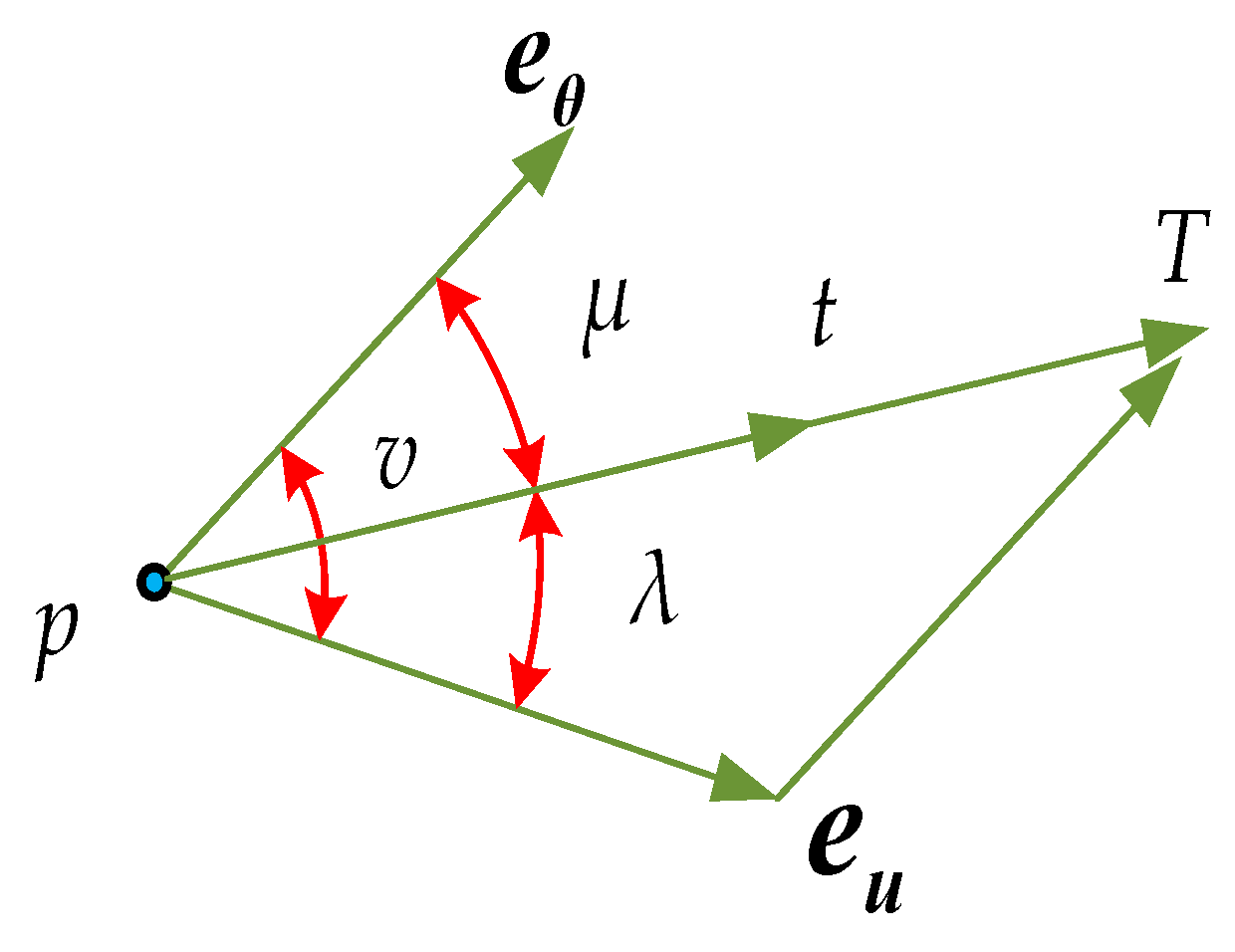
where, μ and λ denote the angles between vectors eu and eθ which are variable parameters, while v = a + b is a constant for a given point on the surface.
The first fundamental form of a surface is represented by the metric tensor.
Ι = d 2 r 2 = e u 2 · d u 2 + 2 e u · e θ · d u · d θ + e θ 2 · d θ 2
The second fundamental form is also given by the metric tensor.
Π = d 2 r · n = 2 r u 2 · n · d u 2 + 2 2 r u θ · n · d u · d θ + 2 r θ 2 · n · d θ 2
From Figure 7, the tangent vector at point p on the surface can be expressed as [34]:
T = a e u + b e θ
where, e u = r u r u , e θ = r θ r θ .
t = e u sin μ + e θ sin ( ν μ ) sin ν
where, t = T T , cosν = eu∙eθ, sinν = |eu × eθ|.
The equation for normal curvature is derived through a derivative transformation of the equation above.
K n = Π Ι = A sin 2 μ + 2 B sin ( ν μ ) sin μ + C sin 2 ( ν μ )
where, A = L r u 2 sin 2 ν , B = M r u r θ sin 2 ν , C = N r θ 2 sin 2 ν .
tan 2 μ = C sin 2 ν 2 B sin ν A 2 B cos ν + C cos 2 ν
Equation (37) provides two solutions, μ1 and μ2, where μ2 = μ1 + π/2. By substituting μ1 and μ2 into Equation (35), the values of the two principal directions at the contact point of the tooth surface can be determined. Substituting these values into Equation (36),the principal curvatures at the point in the two principal directions can be obtained.
By calculating the curvature of the gear with internal and external meshing surfaces, the principal curvature of the nutation gear at the meshing point can be determined using the formula for principal curvature mentioned above.

3.2.2. Hertzian Contact Theory

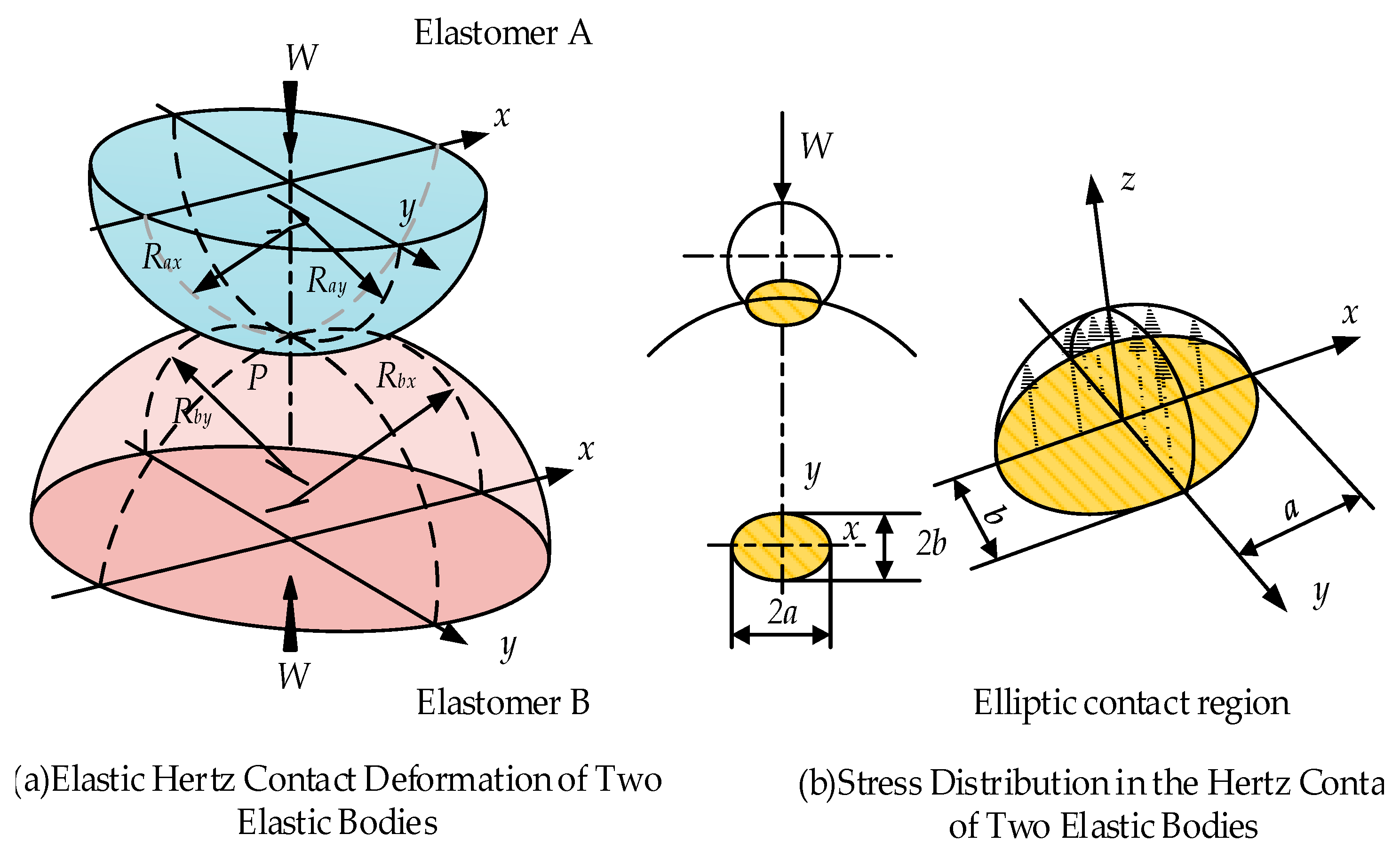
According to Figure 8a,b, there are four planes in Hertzian contact between the curved surfaces, corresponding to the principal curvature surfaces of the two surfaces, respectively. In the contact ellipse, a and b represent the major axis and minor axis of contact, respectively, with the maximum contact stress assumed to be P.
Based on Hertz contact theory analysis, when the elastomers A and B are in contact, the value of a and b in the contact region can be expressed as:
a = 6 k ¯ 2 ε ¯ W R π E 1 / 3 b = 6 ε ¯ W π k ¯ E 1 / 3
where, E′ represents the elastic modulus at the contact point of the ellipse, R′ is the equivalent radius of curvature, k ¯ is the first elliptic integral, and ε ¯ is the second elliptic integral.
1 R = 1 R x + 1 R y = 1 R a x + 1 R b x + 1 R a y + 1 R b y 1 E = 1 2 1 μ A 2 E A + 1 μ B 2 E B k ¯ = 1.0339 R y R x 0.636 ε ¯ = 1.0003 + 0.5968 R y R x
μA and μB are the Poisson’s ratios of elastomers A and B; respectively, while EA and EB elastic moduli of elastomers A and B; Rx and Ry radii of curvature in the x- and y-directions, respectively.
The maximum contact stress P is given by Equation (40).
P = 3 W 2 π a b

4. Design of Face Gear Face Gear Nutation Reducer

Analysis and Design of Nutation Reducer

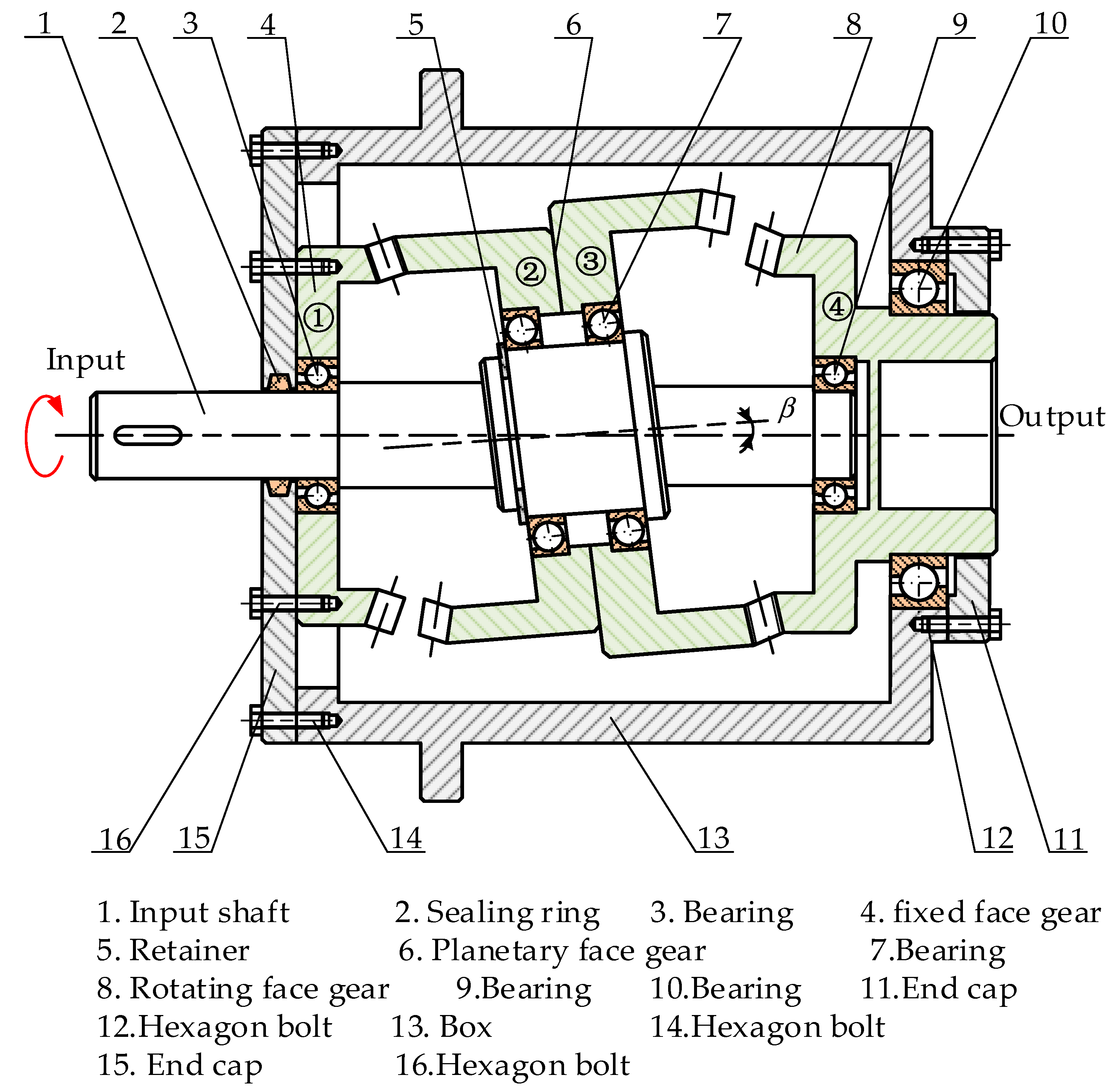
As shown in Figure 9, the basic structure of the nutation reducer consists of four main components: the input shaft, the planetary face gear (which is made up of two face gears), the fixed face gear, and the rotating face gear. The input shaft is connected to the planetary face gear through bearings. The fixed face gear is securely attached to the frame, while the rotating face gear is rigidly connected to the output shaft. The angle between the axis of the input shaft and the axis of the inclined shaft segment, where the planetary gear is located, is known as the nutation angle, denoted as β. The transmission ratio of the nutation reducer is calculated as follows.
The rotation angle formed between face gear 1 and face gear 2 during rotation [36,37].
φ 21 = Z 2 Z 1 Z 2 · 2 π
The rotation angle formedbetween face gear 3 and face gear 4 during rotation.
φ 34 = Z 3 Z 4 Z 4 · 2 π
Due to the fixed connection between face gears 2 and 3, the angle difference is transmitted to face gear 4 through face gear 3. Therefore, the actual angle value of face gear 4 is determined.
φ 4 = Z 3 Z 4 · ( φ 21 φ 34 )
Since face gears 2 and 3 are connected to the input shaft, and face gear 4 is connected to the output shaft, the output angle value is equal to the actual angle value of face gear 4, which defines the transmission ratio of the reducer.
q 14 = 2 π φ 4 = 2 π Z 3 Z 4 ( φ 21 φ 34 ) = Z 2 Z 4 Z 2 Z 4 Z 1 Z 3
In nutation face gear transmission, the planetary face gear rotates around its own axis, exhibiting nutation motion. Based on the structural characteristics of the face gear, when the difference in the number of teeth is no greater than 3, the structural dimensions of the meshing face gears are almost identical. Therefore, in nutation face gear transmission, the number of teeth on each face gear must satisfy the following constraints.
1 Z 2 Z 1 3 1 Z 3 Z 4 3
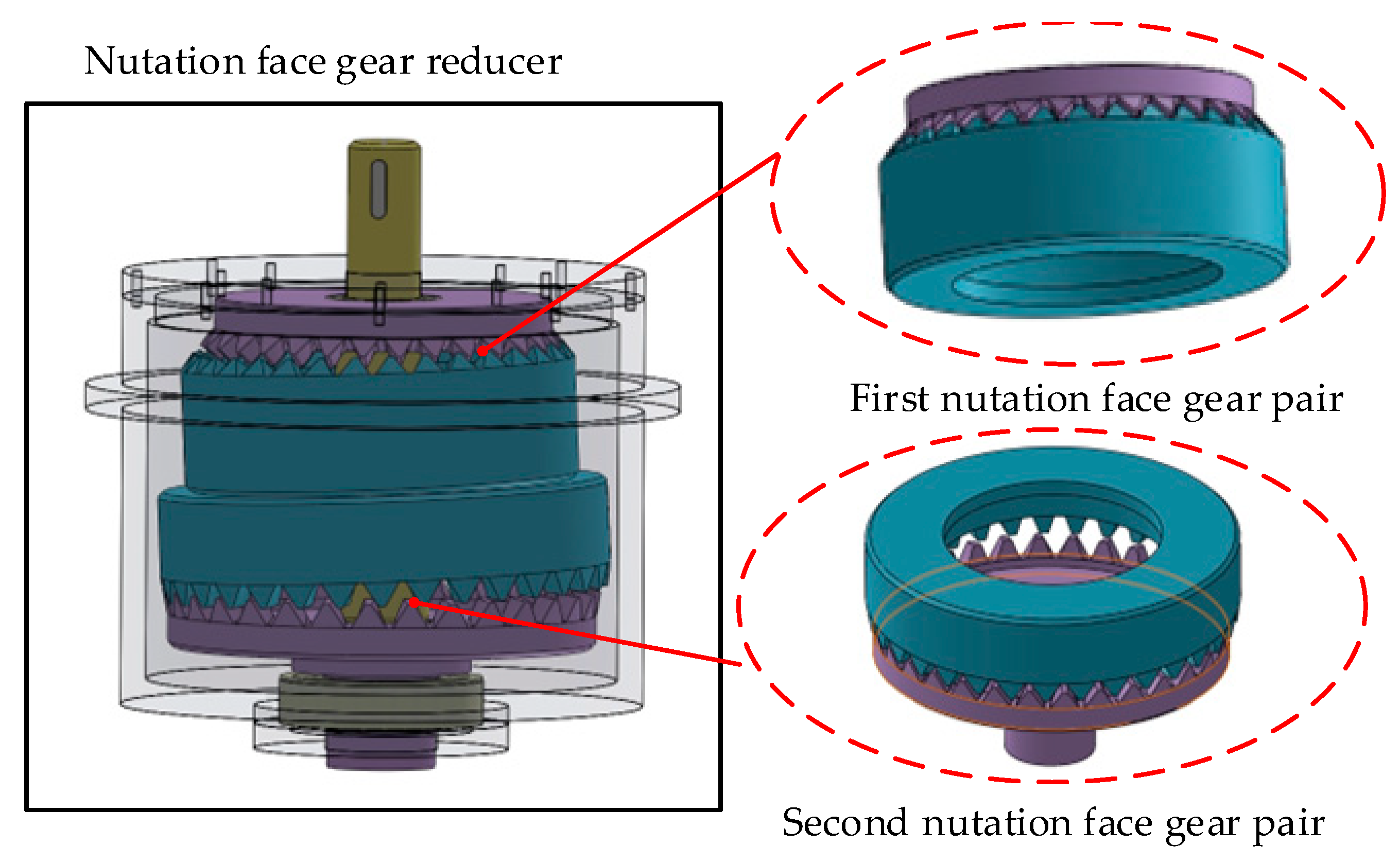
Figure 10 illustrates the face gear nutation reducer. The main body of the nutation reducer consists of two opposing face gear meshing pairs and an input shaft. The output shaft is fixedly connected to the external tangent face gear in the second meshing pair.
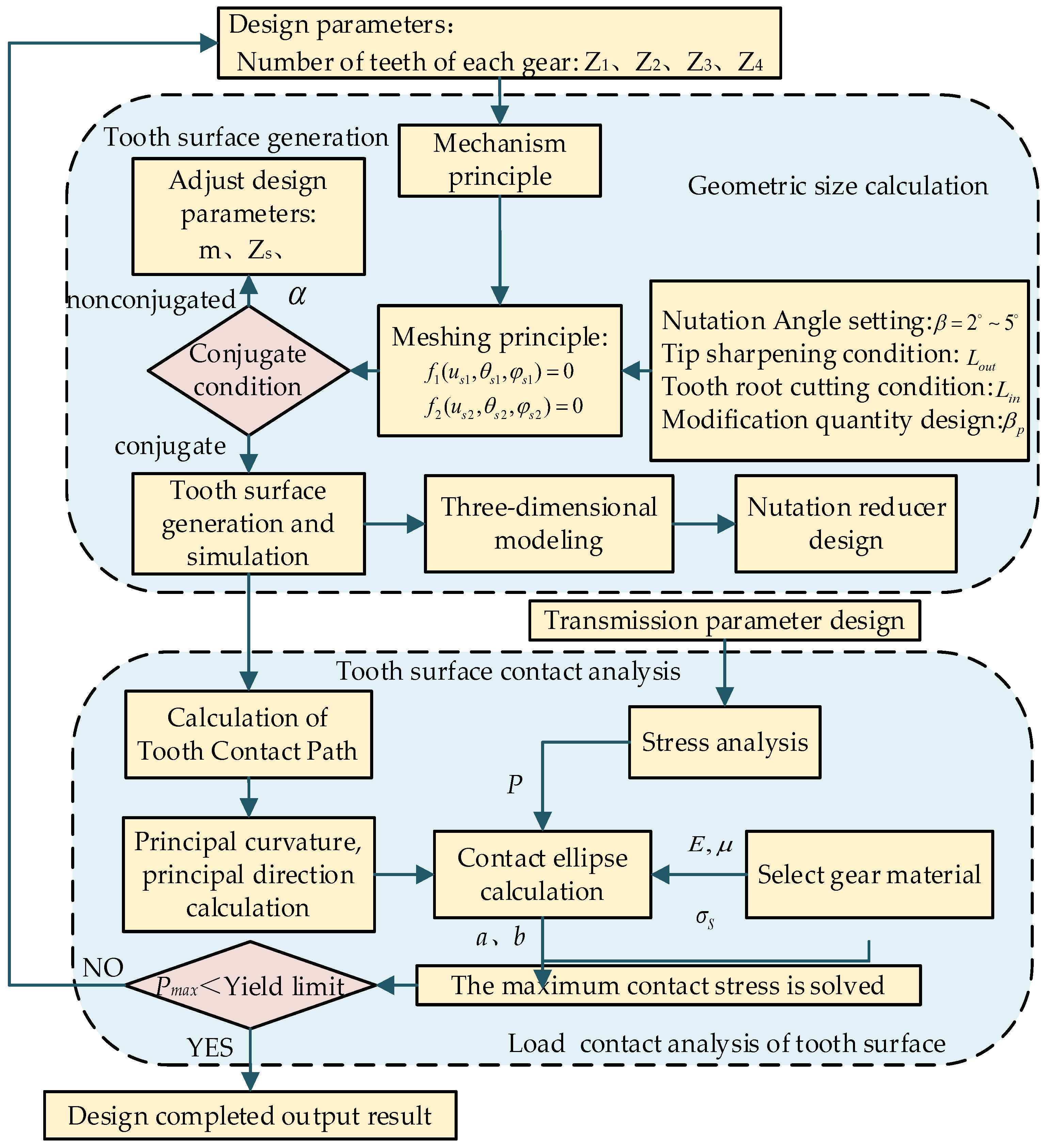
Figure 11 presents the detailed flow chart for the design of the nutation reducer in this paper. The first part covers tooth surface generation, while the second part addresses tooth surface contact analysis.

5. Numerical Examples and Discussions

5.1. Generation of Tooth Surface of Face Gear Face Gear Meshing Pair

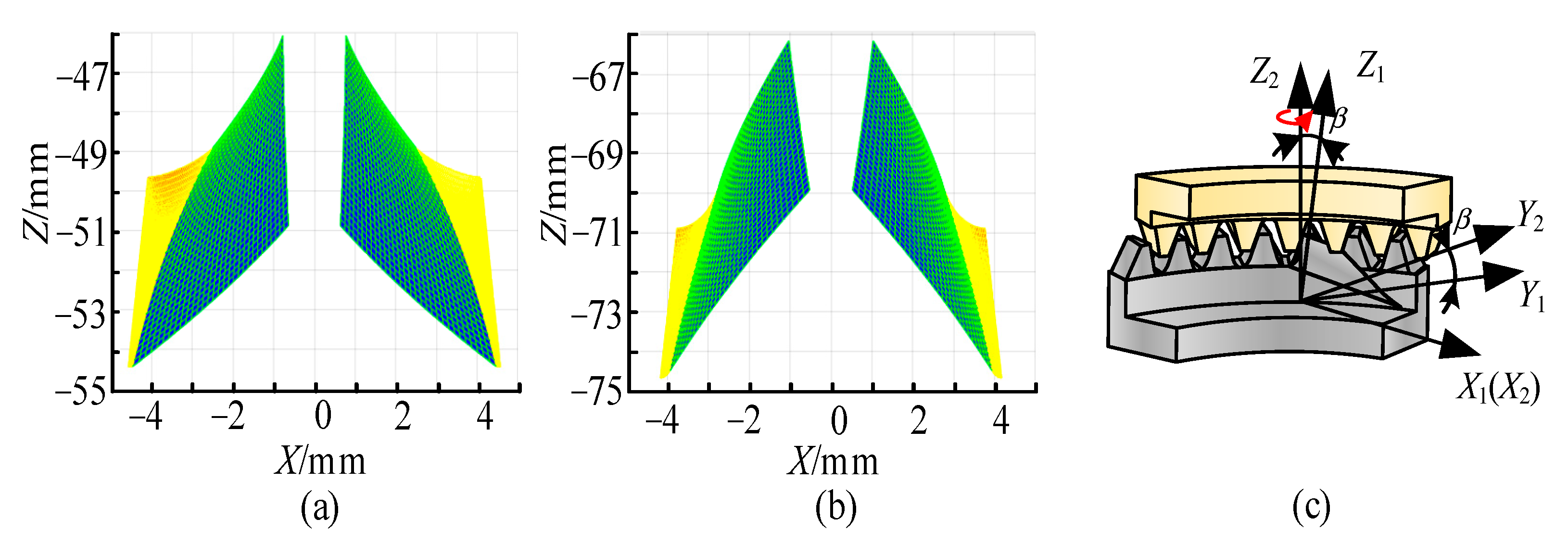
Face gears differ from conventional gears, and the process of establishing a 3D model for face gears is more complex. First, using the tooth surface equation of the face gear, combined with the parameters in Table 1, the 3D model of the face gear’s tooth surface was designed using MATLAB. The coordinate values of the tooth surface were obtained by discretizing the surface through a cell-based method. These coordinates were then imported into SolidWorks, where the 3D solid model of the face gear was generated using the solid command. Figure 12 illustrates the generated external meshing face gear, internal meshing face gear, and the seven-tooth contact model of the face gear meshing pair.

5.2. Analysis of Tooth Contact Path

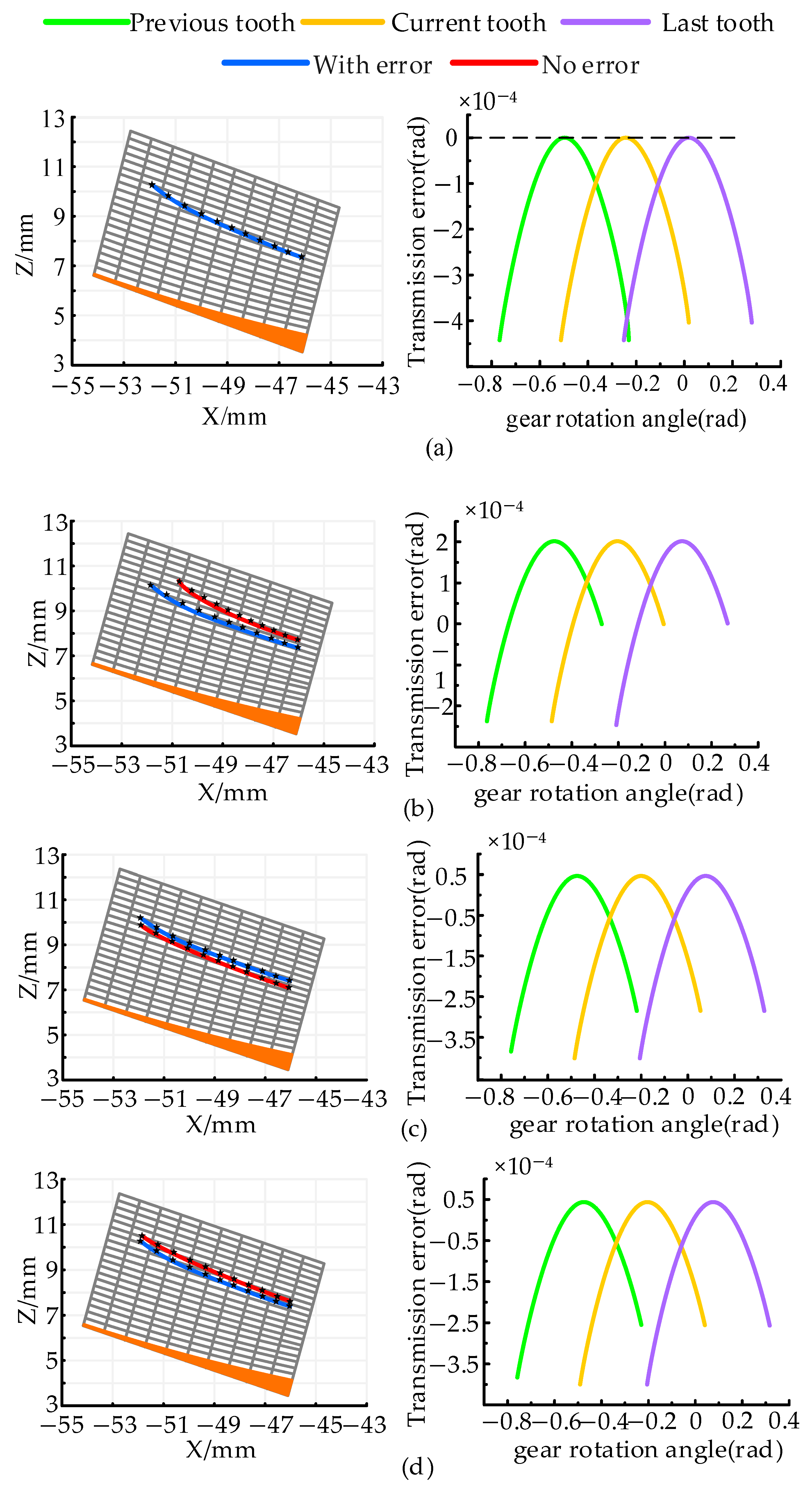
Figure 13a shows the contact path and transmission error curve of the face gear meshing pair under standard installation. From the figure, it is evident that the transmission error value is 1 × 10⁻⁴ rad, and the contact path extends from the tooth root at the inner diameter to the tooth tip at the outer diameter of the face gear. Figure 13c shows that when the offset error ΔE = 0.5 mm, the transmission error value increases to 1.48 × 10⁻⁴ rad. The contact path shifts slightly towards the tooth tip and inner diameter, compared to the ideal installation position. Figure 13d shows that when the axial displacement error Δq = 0.2 mm, the transmission error value is 1.09 × 10⁻⁴ rad. In this case, the contact path moves towards the root and inner diameter, but the deviation is not significant. Figure 13b shows he case with a angle error Δγ = 0.05°, awhere the transmission error value is 0.86 × 10⁻⁴ rad. Compared to the ideal installation position, the contact path deviates significantly towards the tooth tip and inner diameter, with a noticeable shortening of the contact path. In conclusion, the nutation angle error has the greatest impact on the contact path. Since the contact path is less sensitive to offset and axial displacement errors, the influence of modifications on nutation contact is primarily analyzed through the nutation angle error.
Figure 14 illustrates that the two principal curvatures at the meshing point on the tooth surface of the nutation face gear are positive and negative and can vary accordingly. When the two face gears mesh, one of the tooth surfaces is concave and the other is convex. In Figure 14, K1 and K3 represent the principal curvatures of the external meshing face gear, while K2 and K4 represent the principal curvatures of the internal meshing face gear. Along the same line of action, the absolute value of the principal curvature at the meshing point of the tooth surface is inversely related to the value of the tool’s rotation angle, with mild fluctuations in the principal curvature. As shown in Figure 14, the nutation angle error has the greatest impact on the variation in the principal curvature, while the offset and axial displacement errors have a lesser effect, consistent with the influence of installation errors on the contact path discussed earlier.
Table 2 presents the elastic deformation data at the meshing point of the external meshing face gear, calculated using the Hertz contact method, under the condition of no installation error and no modification. This data includes the values for the major and minor axes of the contact ellipse, as well as the maximum contact stress. When the external meshing face gear contacts the internal meshing face gear, the maximum contact stress on the tooth surface is 1592.08 MPa, and the contact stress gradually decreases along the direction of the contact path.

5.3. Tooth Contact Analysis of Face Gear Face Gear Meshing Pair with Modification Machining

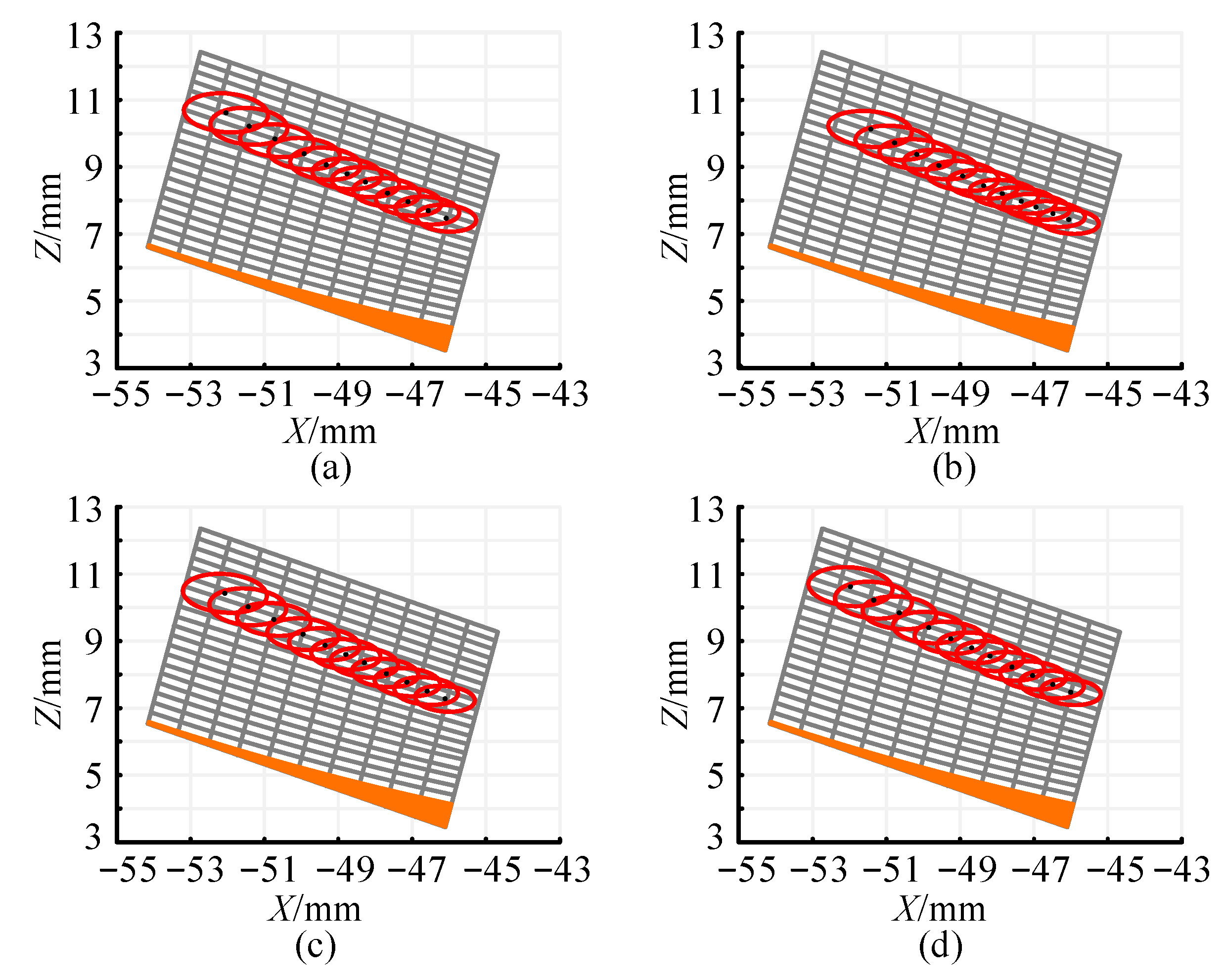
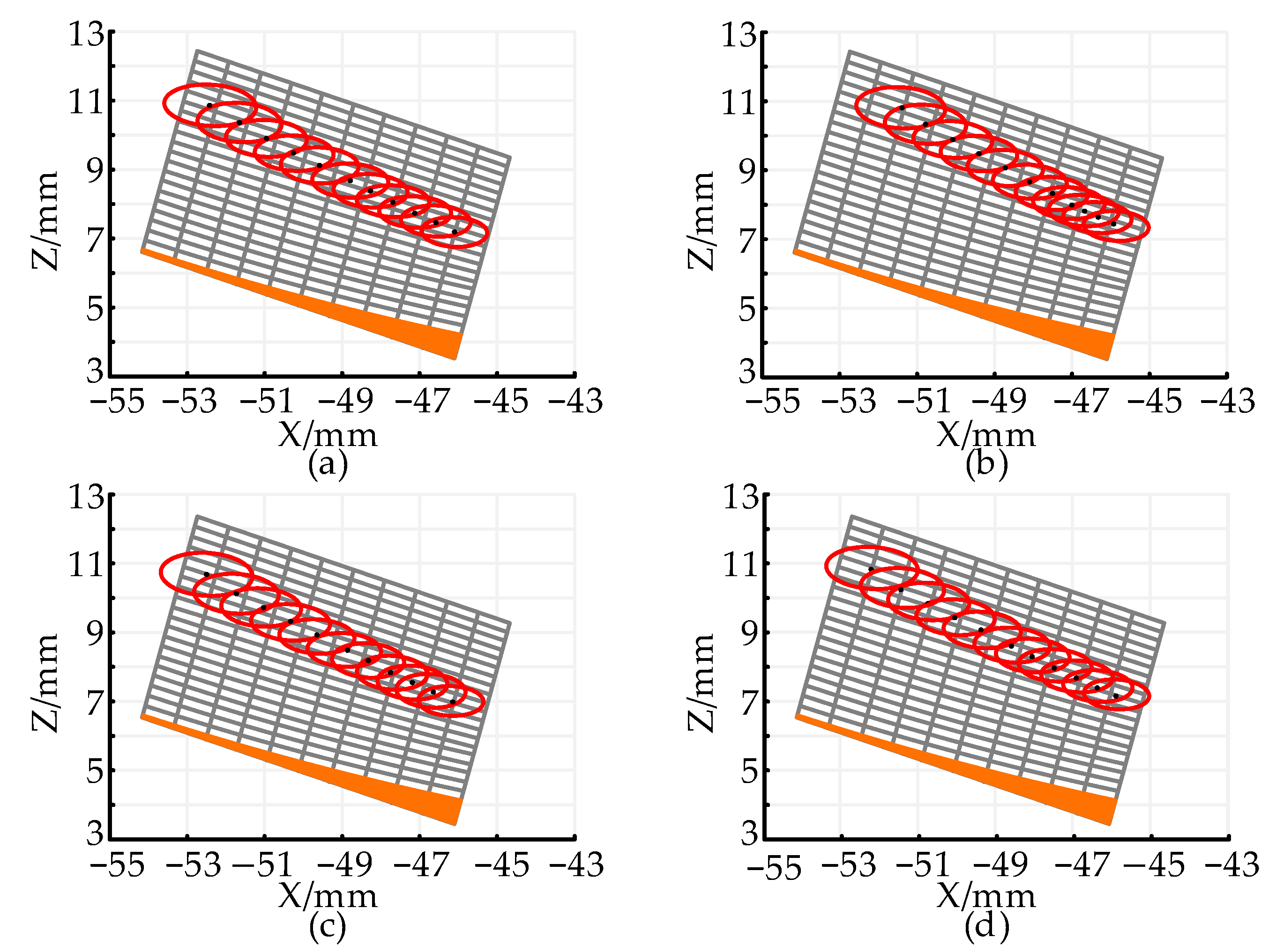
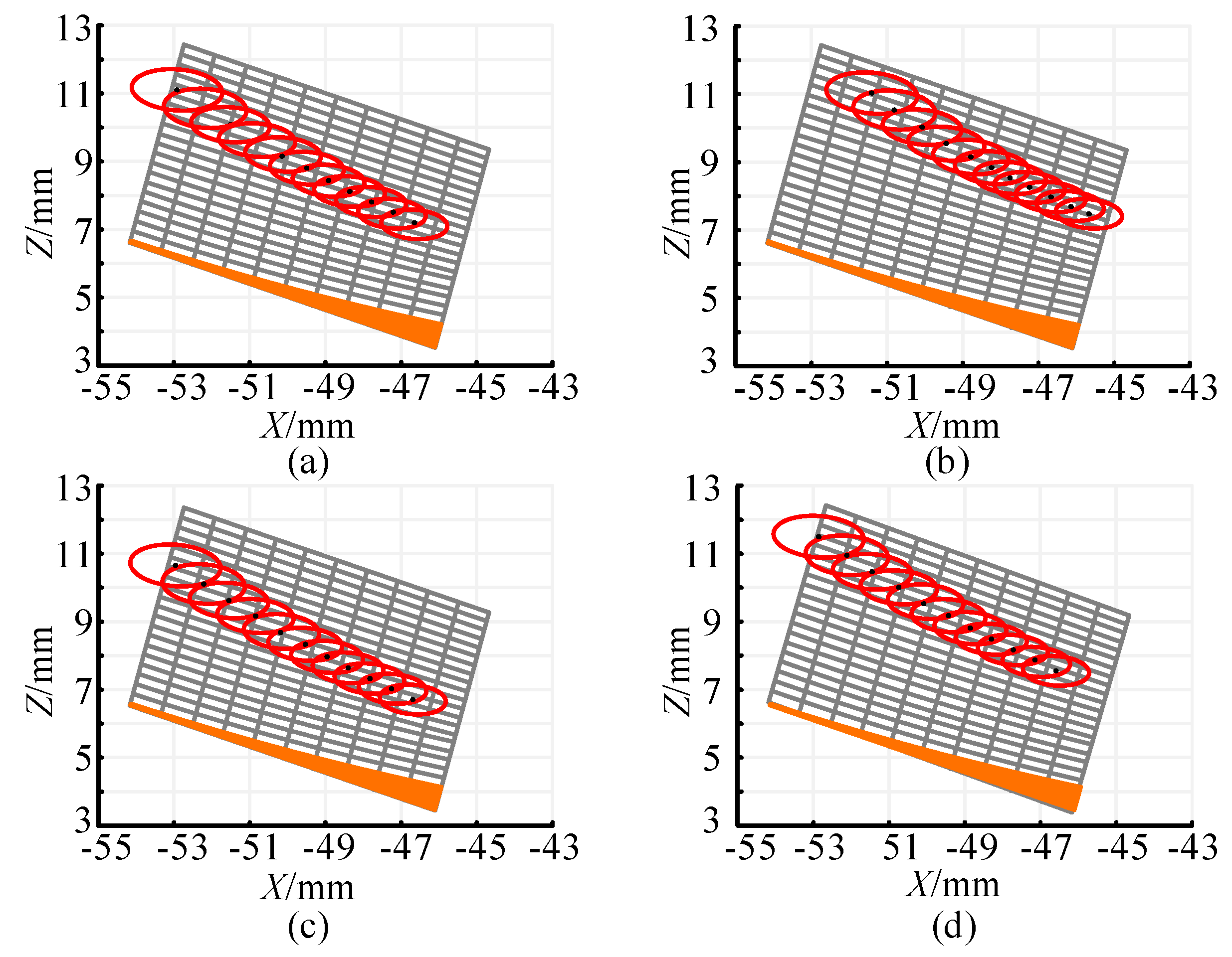
Table 3 lists the modification parameters used in this study. Under the action of load (Tg = 1200 NM), different contact paths for the external meshing face gear can be obtained by modifying (xz, yz) and the rotation angle βp. In this paper, αp = 0.001 is selected, with no changes to (xz, yz), and the value of βp is modified to 0°, −1°, −2°, and −3°. To compare the effects of different modification coefficients on the actual tooth surface of the face gear, the tooth surfaces corresponding to these values are analyzed. The comparative analysis method is as follows: substitute the different modification parameters into the formula.
Figure 15 shows that when βp = 0°, he parabolic modification has minimal impact on the contact path, with no significant changes observed.
Figure 16 shows that when βp = −1°, the contact path extends from the tooth root at the inner diameter to the tooth tip at the outer diameter. The contact path under the four installation conditions is slightly inclined, but the change is not significant. The effective contact path becomes longer with nutation angle error. However, the contact path under offset and axial displacement errors remains largely unchanged, though the contact ellipses increase slightly.
Figure 17 shows that when βp = −2°, the effective contact path under all four installation conditions becomes noticeably longer. The contact path under nutation angle error shows the most significant change, with the contact path clearly tilting and the contact ellipse increasing.
Figure 18 shows when βp = −3°, the inclination becomes more pronounced, and the contact path exceeds the tooth surface. The influence of axial bias error and axial displacement error on the contact path is amplified.

5.4. Contact Stress Analysis

In the meshing process of transmission, under load, the teeth of the nutation face gear will undergo elastic deformation. However, this does not significantly affect the transmission performance. In contrast, if the teeth undergo plastic deformation, the transmission performance will be greatly reduced.
The maximum Mises stresses follow the fourth strength theory in material mechanics, also known as the distortion energy theory, which considers material deformation as the primary form of material failure. Using finite element software, the nutation face gear drive is analyzed, and the maximum Mises stress at the gear tooth contact is obtained to evaluate the performance of the nutation face gear drive.
When using ANSYS to analyze the contact stress of a gear transmission with a small number of teeth, the main steps include pre-processing, solving, and post-processing. The specific steps are as follows:
(1)
Creation of nutating face gear transmission components.
(2)
Selection of materials for the nutation face gear, with material parameters shown in Table 4.
(3)
Preliminary meshing of the nutating face gear. After importing the small-tooth differential gear assembly model, redundant contacts may exist that can affect subsequent loading analysis. Therefore, it is necessary to delete the existing contacts first and then perform preliminary meshing to determine if the imported 3D model is suitable for finite element analysis.
(4)
Determination of the connection relationships for the nutating face gear. To determine the size and distribution of contact stress during the re-meshing transmission process, it is necessary to simulate the meshing process, add two rotary connection pairs, and introduce frictional contact at the meshing tooth surfaces to simulate gear tooth engagement.
(5)
Final meshing of the nutating face gear. Since the contact stress of gear meshing is the primary focus of the analysis, the mesh type is defined as tetrahedral.
(6)
Setting of loading conditions for the nutating face gear. A torque of 1200 Nm is applied along the axial direction of the internal gear to simulate the contact behavior of the internal meshing face gear in a new energy vehicle.
(7)
Solution and post-processing for the nutating face gear.
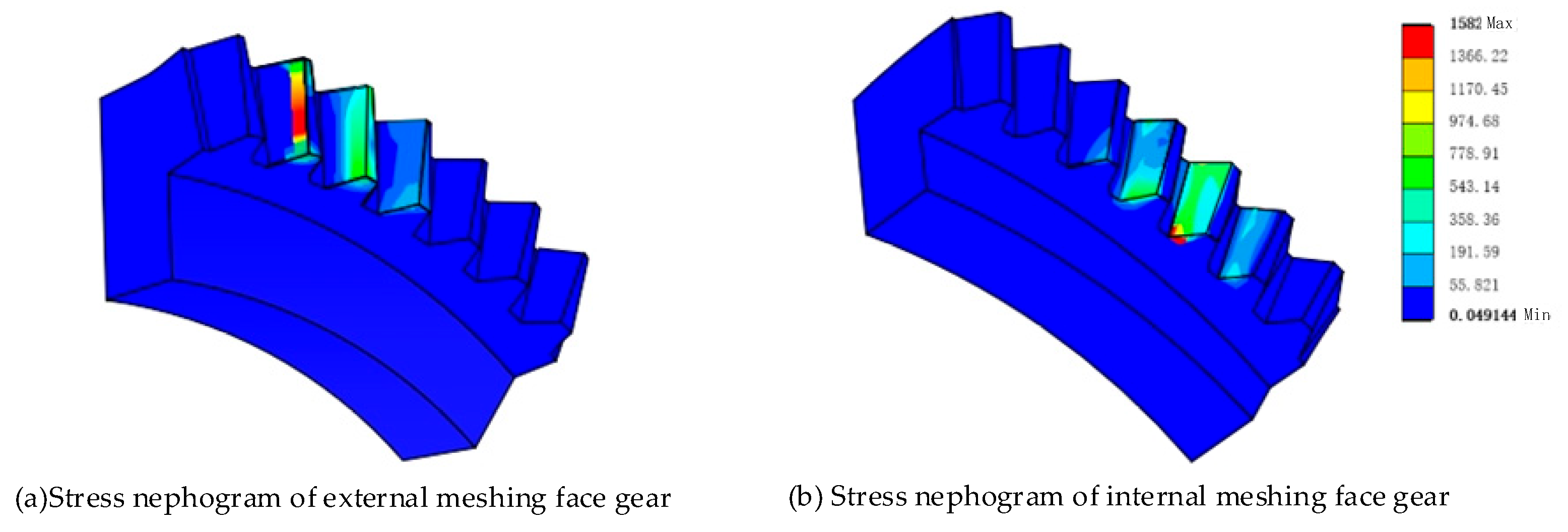
As shown in Figure 19, the maximum contact stress occurs at the tip area of the gear teeth, indicating that this area is prone to contact fatigue failure first. The load condition of the face gear can be improved by modifying the meshing area or increasing the number of teeth. The primary method used in this study is tooth modification.
Figure 20 shows the maximum contact stress of both the external and internal meshing face gears under different modification angles. The calculation results obtained from the analytical method are similar to those obtained from the finite element method (FEM), with the maximum stress error between the two methods being no greater than 10%. This confirms the validity of the constructed force model.
As the modification angle (βp) decreases, the maximum contact stress gradually decreases. When βp = −1°, he contact stress is significantly reduced. At βp = −2°, the maximum stress of both the external and internal meshing face gears reaches its minimum value according to both the analytical and FEM methods. However, when βp = −3°, the maximum contact stress increases again. As shown in Figure 18, the contact ellipse formed by the loading extends beyond the tooth surface boundary, leading to a significant increase in contact stress.

6. Conclusions

This paper proposes a method to improve the nutation reducer by replacing the internal meshing bevel gear pair with a face gear-face gear meshing pair. Based on this approach, a mathematical model for the face gear-face gear meshing pair is established, and the geometric contact analysis of the meshing pair is conducted. The feasibility of this method is verified by simulation results, and a face gear-face gear meshing nutation reducer is ultimately designed. The following conclusions can be drawn from this study:
(1)
The external meshing face gear and the internal meshing face gear, manufactured using the same tool, can conjugate and mesh to form a face gear-face gear pair.
(2)
For the face gear, a modification method based on parabolic modification with an adjustment of the angle βp is proposed. Compared to simple parabolic modification, this method is more suitable for nutation face gear transmission. The new modification technique improves meshing performance and reduces contact stress. However, when βp becomes too small, the contact ellipse formed by the load extends beyond the tooth surface boundary, resulting in a surge in contact stress.
(3)
The impact of installation errors on the contact path of the face gear-face gear meshing pair is analyzed. The results show that, compared to axis bias and axial displacement errors, the nutation angle error has the most significant effect on the contact path. This is because the nutation angle error not only directly alters the position and distribution of the contact points but also causes a substantial change in the main curvature of the tooth surface, particularly in the tooth top and outer diameter areas. This has a major impact on the TCA results. Additionally, the nutation angle error has global and cumulative effects, making its influence much greater than other local errors.
(4)
According to the ANSYS contact analysis results, the maximum contact stress occurs at the internal tooth tip area of the face gear. The contact stress distribution is consistent with the calculated value from Hertzian elastic contact theory, as described in Section 5.2. The maximum contact stress is approximately 1500 MPa, indicating that this area is most susceptible to contact fatigue failure. It is also observed that the nutating face gear transmission involves multi-tooth meshing with significant overlap and good power splitting characteristics. However, edge contact occurs, necessitating subsequent tooth surface modifications to resolve the issue.

Author Contributions

Writing—original draft, H.C. and Q.L.; Writing—review & editing, C.J. All authors have read and agreed to the published version of the manuscript.

Funding

The work described in this paper was supported by the National Natural Science Foundation of China (Grant No. 52375044).

Data Availability Statement

The original contributions presented in this study are included in the article.

Conflicts of Interest

The authors declare no conflict of interest.

Abbreviations

Notation
a, b major and minor axis of contact ellipse
α pressure angle
β nutation angle
βp tooth surface rotation angle
γ tooth surface rotation angle
θn tooth profile parameters of the involute tooth profile, n = s, s1, s2
φn the rotation angle, n = s, 1, 2, 3, 4
Δφ2 transmission error
Δm amount of modification
Δγ nutation angle error
ΔE offset error
Δq axial displacement error
a, b major and minor axis of contact ellipse
ap parabolic modification coefficient
i reducer ratio
Kn curvature of surface, n = 1, 2, 3, 4
Lin minimum inner radius of face gear
Lout maximum outer radius of the face gear
Lij 3 × 3 matrix of coordinate transformation from system sj to system si
Mij 4 × 4 matrix of coordinate transformation from system sj to system si
P maximum contact stress
Tg load
Zn(n = s, 1, 2, 3, 4) tooth numbers of pinion and gear, n = s, 1, 2, 3, 4
Abbreviations
PMT peripheral ring transmission
DCAP double circular-arc profile
TCA tooth contact analysis
LTCA loaded tooth contact analysis
AM analytical method
FEM finite element method

Appendix A. Transformation Matrixes

M S 10 S 1 = cos φ s 1 sin φ s 1 0 0 sin φ s 1 cos φ s 1 0 0 0 0 1 0 0 0 0 1
M 10 S 10 = 1 0 0 0 0 cos π γ 1 sin π γ 1 0 0 sin π γ 1 cos π γ 1 0 0 0 0 1
M 110 = cos φ 1 sin φ 1 0 0 sin φ 1 cos φ 1 0 0 0 0 1 0 0 0 0 1
M S 20 S 2 = cos φ s 2 sin φ s 2 0 0 sin φ s 2 cos φ s 2 0 0 0 0 1 0 0 0 0 1
M 20 S 20 = 1 0 0 0 0 cos γ 2 sin γ 2 0 0 sin γ 2 cos γ 2 0 0 0 0 1
M 220 = cos φ 2 sin φ 2 0 0 sin φ 2 cos φ 2 0 0 0 0 1 0 0 0 0 1
M f m = 1 0 0 Δ E 0 1 0 0 0 0 1 0 0 0 0 1
M m q = 1 0 0 0 0 cos γ 2 sin γ 2 0 0 sin γ 2 cos γ 2 0 0 0 0 1
M q k = 1 0 0 0 0 1 0 0 0 0 1 Δ q 0 0 0 1
M k 2 = cos φ 2 sin φ 2 0 0 sin φ 2 cos φ 2 0 0 0 0 1 0 0 0 0 1

References

  1. Cai, Y.; Yao, L.; Zhang, J.; Xie, Z.; Hong, J. Feasibility analysis of using a two-stage nutation drive as joint reducer for industrial robots. J. Mech. Sci. Technol. 2019, 33, 1799–1807. [Google Scholar] [CrossRef]
  2. Saribay, Z.B.; Bill, R.C. Design analysis of pericyclic mechanical transmission system. Mech. Mach. Theory 2013, 61, 102–122. [Google Scholar] [CrossRef]
  3. Stadtfeld, H.J. Introduction to Electric Vehicle Transmissions. Gear Technol. 2020, 37, 42–50. [Google Scholar]
  4. Stadtfeld, H.; Ligata, H. Double Differential for Electric Vehicle and Hybrid Transmissions. In Gear Technology Magazine; American Gear Manufacturers Association: Elk Grove Village, IL, USA, 2022. [Google Scholar]
  5. Yamamori, M. Nutation Gear Device, Variable Transmission Ratio Mechanism and Steering Device for Vehicles. China Patent ZL201010129312, 15 September 2012. [Google Scholar]
  6. Cheng, Z.; Xian, M. Practicability analysis of involute less tooth difference bevel gear planetary transmission (nutation transmission). J. Mech. Transm. 2000, 24, 31–33. [Google Scholar]
  7. Yu, Y.; Zhang, J.; Yu, W. Analysis and optimization of gyro moment in nutation drive of bevel differential. Mach. Tool Hydraul. 2001, 110, 32–33. [Google Scholar]
  8. Hu, Y.-p. 3D Parametric Modeling of Internal Bevel Gear Based on UG. J. Kunming Univ. Sci. Technol. 2006, 4, 34–48. [Google Scholar]
  9. Lin, Z.; Yao, L.G. Mathematical Model and 3D Modeling of Involute Spiral Bevel Gears for Nutation Drive. Adv. Mater. Res. 2013, 503, 694–697. [Google Scholar] [CrossRef]
  10. Cai, G.; Li, X. Kinematic analysis of internal bevel gear nutation drives. Mech. Des. Res. 2019, 35, 72–74. [Google Scholar]
  11. Mathur, T.D.; Smith, E.C.; DeSmidt, H.; Bill, R.C. Load Distribution and Mesh Stiffness Analysis of an Internal- External Bevel Gear Pair in a Pericyclic Drive. In Proceedings of the 72nd American Helicopter Society International Annual Forum 2016, West Palm Beach, FL, USA, 17–19 May 2016. [Google Scholar]
  12. Saribay, Z.B. Tooth geometry and bending stress analysis of conjugate meshing face-gear pairs. Proc. Inst. Mech. Eng. Part C J. Mech. Eng. Sci. 2013, 227, 1302–1314. [Google Scholar] [CrossRef]
  13. Gu, B.; Yao, L.G.; Wei, G.W.; Cai, Y.J.; Dai, J.S. The analysis and modeling for mutation drives with double circular-arc: Helical bevel gears. Materials Science Forum 2006, 505–507, 949–954. [Google Scholar]
  14. Shih, Y.; Fong, Z.; Lin, G.C.Y. Mathematical model for a universal face hobbing hypoid gear generator. J. Mech. Design 2007, 129, 38–47. [Google Scholar] [CrossRef]
  15. Shih, Y.; Fong, Z. Flank modification methodology for face-hobbing hypoid gears based on ease-off topography. J. Mech. Design 2007, 129, 1294–1302. [Google Scholar] [CrossRef]
  16. Simon, V.V. Optimal machine tool settings for face-hobbed hypoid gears manufactured on CNC hypoid generator. Int. J. Adv. Manuf. Technol. 2017, 88, 1579–1594. [Google Scholar] [CrossRef]
  17. Simon, V.V. Multi-objective optimization of the manufacture of face-milled hypoid gears on numerical controlled machine tool. Proc. Inst. Mech. Eng. Part B J. Eng. Manuf. 2021, 235, 1120–1130. [Google Scholar] [CrossRef]
  18. Deng, X.; Li, G.; Wei, B.; Deng, J. Face-milling spiral bevel gear tooth surfaces by application of 5-axis CNC machine tool. Int. J. Adv. Manufact. Technol. 2013, 71, 1049–1057. [Google Scholar] [CrossRef]
  19. Tang, W.; Huang, Y.; Wu, Y.; Yao, L.; Pan, L.; Zhang, J. Geometry design, meshing analysis and error influences of face-hobbed cycloidal bevel gears with double circular-arc profile for a nutation drive. Mech. Mach. Theory 2022, 176, 105001. [Google Scholar] [CrossRef]
  20. Litvin, F.L.; Fuentes, A.; Howkins, M. Design, generation and TCA of new type of asymmetric face-gear drive with modified geometry. Comput. Methods Appl. Mech. Eng. 2001, 190, 5837–5865. [Google Scholar] [CrossRef]
  21. Litvin, F.L.; Gonzalez-Perez, I.; Fuentes, A.; Vecchiato, D.; Hansen, B.D.; Binney, D. Design, generation and stress analysis of face-gear drive with helical pinion. Comput. Methods Appl. Mech. Eng. 2005, 194, 3870–3901. [Google Scholar] [CrossRef]
  22. Mo, S.; Luo, B.; Song, W.; Zhang, Y.; Cen, G.; Bao, H. Geometry design and tooth contact analysis of non-orthogonal asymmetric helical face gear drives. Mech. Mach. Theory 2022, 173, 104831. [Google Scholar] [CrossRef]
  23. Meyer, M. Technology behind Cykro® (face) gears and their possibilities. In Proceedings of the International Conference on Gears, Munich, Germany, 13–15 March 2002; Volume 1–2, pp. 75–89. [Google Scholar]
  24. Litvin, F.L.; Chen, N.X.; Lu, J.; Handschuh, R.F. Computerized design and generation of low-noise helical gears with modified surface-topology. J. Mech. Design 1995, 117, 254–261. [Google Scholar] [CrossRef]
  25. Zanzi, C.; Pedrero, J.I. Application of modified geometry of face gear drive. Comput. Methods Appl. Mech. Eng. 2005, 194, 3047–3066. [Google Scholar] [CrossRef]
  26. Zhang, Y.; Wu, Z. Offset face gear drives: Tooth geometry and contact analysis. J. Mech. Design 1997, 119, 114–119. [Google Scholar] [CrossRef]
  27. Liu, D.; Wang, G.; Ren, T. Transmission principle and geometrical model of eccentric face gear. Mech. Mach. Theory 2017, 109, 51–64. [Google Scholar] [CrossRef]
  28. Kawasaki, K.; Tsuji, I.; Gunbara, H. Geometric design of a face gear drive with a helical pinion. J. Mech. Sci. Technol. 2018, 32, 1653–1659. [Google Scholar] [CrossRef]
  29. Feng, G.; Xie, Z.; Zhou, M. Geometric design and analysis of face-gear drive with involute helical pinion. Mech. Mach. Theory 2019, 134, 169–196. [Google Scholar] [CrossRef]
  30. Zhu, L.; Shi, J.; Gou, X. Modeling and dynamics analyzing of a torsional-bending-pendular face-gear drive system considering multi-state engagements. Mech. Mach. Theory 2020, 149, 103790. [Google Scholar] [CrossRef]
  31. Zschippang, H.A.; Weikert, S.; Kucuk, K.A.; Wegener, K. Face-gear drive: Geometry generation and tooth contact analysis. Mech. Mach. Theory 2019, 142, 103576. [Google Scholar] [CrossRef]
  32. Peng, X.; Zhou, J. Optimization design for dynamic characteristics of face gear drive with surface-active modification. Mech. Mach. Theory 2022, 176, 105007. [Google Scholar] [CrossRef]
  33. Hochrein, J.; Otto, M.; Stahl, K. Face gear drives: Nominal contact stress calculation for flank load carrying capacity evaluation. Mech. Mach. Theory 2024, 195, 105573. [Google Scholar] [CrossRef]
  34. Litvin, F.L.; Fuentes, A. Gear Geometry and Applied Theory, 1st ed.; PTR Prentice Hall: Englevood Cliffs, NJ, USA, 1994. [Google Scholar]
  35. Stachowiak, G.; Batchelor, A.W. Engineering Tribology; Butterworth-Heinemann: Oxford, UK, 2006. [Google Scholar]
  36. Saribay, Z.B.; Bill, R.C.; Smith, E.C.; Rao, S.B. Elastohydrodynamic Lubrication Analysis of Conjugate Meshing Face Gear Pairs. J. Am. Helicopter Soc. 2012, 57, 1–10. [Google Scholar] [CrossRef]
  37. Saribay, Z.B. Analytical Investigation of the Pericyclic Variable-Speed Transmission System for Helicopter Main-Gearbox. Ph.D. Thesis, Pennsylvania State University, University Park, PA, USA, 2009. [Google Scholar]
Figure 1. Schematic representation of gear machining with different shaft angles: (a) γ < 90°; (b) γ = 90°; (c) γ > 90°.
Mathematics 13 00476 g001
Figure 2. Tooth profile of shaper cutter.
Mathematics 13 00476 g002
Figure 3. Illustration of generation of internal and external meshing face gear. (a) External meshing face gear; (b) Internal meshing face gear.
Mathematics 13 00476 g003
Figure 4. Schematic diagram of undercutting and pointing.
Mathematics 13 00476 g004
Figure 5. Schematic diagram of the modification of the shaper cutter.
Mathematics 13 00476 g005
Figure 6. Relationship between coordinate systems.
Mathematics 13 00476 g006
Figure 7. Tangents to coordinate curves on surfaces.
Mathematics 13 00476 g007
Figure 8. Schematic diagram of the contact between elastomers.
Mathematics 13 00476 g008
Figure 9. Schematic diagram of nutation reducer.
Mathematics 13 00476 g009
Figure 10. Three-dimensional schematic diagram of nutation reducer assembly.
Mathematics 13 00476 g010
Figure 11. Design flow chart of nutation reducer.
Mathematics 13 00476 g011
Figure 12. (a) External meshing face gear; (b) Internal meshing face gear; (c) Seven-tooth contact model of face gear face gear meshing pair.
Mathematics 13 00476 g012
Figure 13. Diagram of the contact path and transmission error under the installation error. (a) Standard installation; (b) Δγ = 0.05°; (c) ΔΕ = 0.3; (d) Δq = 0.2.
Mathematics 13 00476 g013
Figure 14. Principal curvature plot under installation error. (a) Standard installation; (b) Δγ = 0.05°; (c) ΔΕ = 0.3; (d) Δq = 0.2.
Mathematics 13 00476 g014
Figure 15. βp = 0° (a) Standard installation; (b) Δγ = 0.05°; (c) ΔΕ = 0.3; (d) Δq = 0.2.
Mathematics 13 00476 g015
Figure 16. βp = −1° (a) Standard installation; (b) Δγ = 0.05°; (c) ΔΕ = 0.3; (d) Δq = 0.2.
Mathematics 13 00476 g016
Figure 17. βp = −2° (a) Standard installation; (b) Δγ = 0.05°; (c) ΔΕ = 0.3; (d) Δq = 0.2.
Mathematics 13 00476 g017
Figure 18. βp = −3° (a) Standard installation; (b) Δγ = 0.05°; (c) ΔΕ = 0.3; (d) Δq = 0.2.
Mathematics 13 00476 g018
Figure 19. Stress nephogram of internal meshing face gear.
Mathematics 13 00476 g019
Figure 20. Maximum contact stress of external meshing face gear and internal meshing face gear under different modification angles.
Mathematics 13 00476 g020
Table 1. Design parameters of face gear face gear meshing pair.
Design ParametersExternal Meshing Face GearInternal Meshing Face Gear
Module m/mm33
Tooth count of the hobbing cutter Zs1616
Tool pressure angle αs/mm2525
Addendum coefficient ha*1.251.25
Teeth number Zn2931
Cross axis angle/°50.31127.19
Pitch cone angle/°33.67143.82
Nutation angle β/°2.52.5
Tooth width b/mm88
Offset error/mm0.3
Axial displacement error/mm0.2
Nutation angle error/mm0.05
Table 2. Calculation results of hertz elastic contact method.
Contact PointMajor AxisMinor AxisMaximum Contact Stress
11.8021.4761592.08
21.8881.4761463.18
32.0001.5041374.02
42.1081.5341291.12
52.2141.5651216.65
62.5181.5961148.90
72.4201.6291087.09
82.5231.6621030.06
92.6251.696976.04
102.7291.731927.53
112.8331.767880.98
Table 3. Parameters of different modification.
Case1 Case2 Case3 Case4
arabola modification coefficient αp/mm0.0010.0010.0010.001
Modified coordinates origin xz/mm 0.0190.0190.0190.019
Modified coordinates origin yz/mm −24.213−24.213−24.213−24.213
Modified rotation angle βp 0 −1−2−3
Table 4. Face gear material parameter values.
MaterialDensity (kg/m3)Elastic Modulus (GPa)Poisson’s Ratio
20Cr2Ni4A78002110.30
Disclaimer/Publisher’s Note: The statements, opinions and data contained in all publications are solely those of the individual author(s) and contributor(s) and not of MDPI and/or the editor(s). MDPI and/or the editor(s) disclaim responsibility for any injury to people or property resulting from any ideas, methods, instructions or products referred to in the content.