Abstract
Many applications of quantum computers require the classical and quantum implementation of dynamic systems (DSs). These applications comprise interacting quantum and classical tasks. While quantum tasks evolve in the quantum domain, classical tasks behave in the classical domain. Besides tackling these kinds of tasks, the computational gap between these domains is covered by the current study. The quantum computing feature All at Once (A@O) executions is appropriate for static systems but less for DSs. The novelty of the proposed approach consists of using Distributed Quantum-Centric Petri Net (DQCPN) models composed of quantum and high-level Petri Nets for specification, design, verification, and implementation of classical–quantum applications. Quantum Processing Units (QPUs) are linked to classical components implementing the control and optimization operations in the proposed application. Many practical applications combine quantum and classical computing to address optimization problems. Quantum computers can be built with a combination of qubits and bosonic qumodes, leading to a new paradigm toward quantum computing. The optimizations are performed by some Evolutionary Algorithms (EAs), including Particle Swarm Optimization (PSO) methods and Genetic Algorithms (GAs). For experiments, an Urban Vehicle Traffic System (UVTS) is used as an open distributed system. The vehicle flows are implemented by discrete qubits, discrete vectors of qubits, or qumodes.
Keywords:
quantum-centric computing; hybrid computing; Petri nets; quantum Petri nets; dynamic systems; quantum processor unit control; qubits; qumodes MSC:
93-10
1. Introduction
Quantum and classical computing are increasingly combined to address optimization problems [1]. Quantum computers may integrate qubits and bosonic qumodes, introducing a new paradigm. While qubits are implemented on quantum superconductivity hardware at cryogenic temperatures, qumodes are realized on optical processors operating at room temperature.
Practical applications of quantum computing include the following:
- Artificial intelligence (AI) and machine learning (e.g., quantum-inspired tensor neural networks for quantum machine learning and quantum generative AI);
- Financial modeling for market prediction and risk management;
- Manufacturing resilience, for identifying components that contribute to incidents of product failure;
- Secure communications and access control for blockchain or quantum cryptography;
- Cybersecurity;
- Material science, for finding molecules with more complex interactions;
- Drug and chemical research for new-drug finding;
- Weather forecasting and climate change;
- Electrical power system balance, and scheduling and control;
- Route and traffic optimization for finding the shortest possible route between cities or traffic flows;
- Complex circuit design;
- Complex structure synthesis;
- Automotive industry (e.g., improved battery conception);
- Quantum computing applied to natural language processing;
- Quantum computing for task optimization;
- Quantum sensing (environmental monitoring, medical imaging, geological exploration, etc.).
1.1. Development of Quantum Software Application
The practical use of quantum computing requires accessible and effective programming development methods. Several important approaches for solving quantum computing problems are analyzed in [2].
According to [3], there is a strong need for simulators and design environments focused more on software design than on quantum circuits. This refers to the high-level design of hybrid software systems, often incorporating existing modeling languages and methodologies.
As noted in [4], tools that allow programmers to work at the algorithmic level rather than dealing with hardware organization and low-level optimization are required. Similar to classical computing, a complete life cycle of quantum computing tools, methods, and procedures must be provided.
A quantum programming environment is described in [5], consisting of a platform that includes a compiler of the quantum while-language, together with tools for simulating quantum computation, optimizing quantum circuits, and analyzing and verifying quantum programs.
A survey of architectures and demands for software in quantum computing is provided in [6], while quantum model development architectures are systematically reviewed in [7], including architecture-centric solutions and emerging challenges.
Language-level extensions have also been proposed. For instance, [8] extends C++ with quantum operations for hybrid implementations, and [9] introduces Q#, an algorithm definition language in which the quantum program operates as a co-processor to the classical machine.
Another direction is quantum service-oriented computing [10], whose evaluation considers qubit count, number of shots, precision, response time, and cost.
Our proposed approach builds on these architectural, modeling, validation, and deployment requirements but also emphasizes analysis and verification. Petri Nets (PNs), widely used in classical software verification, are extended here to support quantum computing.
1.2. Dynamic Systems
A dynamic system (DS) consists of related elements (variables) whose relationships evolve over time. The term dynamic highlights continual or discrete changes, while dynamical emphasizes the study of such evolution. DS behavior can be mathematically modeled through variables and their interactions, governed by rules that describe state dependence on a parameter called time.
Time may be discrete (), continuous (), complex (), or multi-dimensional subsets of . The collection of states defines the system’s state space, which may be discrete, continuous, or multi-dimensional. Rule application defines state transitions and, over multiple applications, system evolution. Rules may involve fixed or time-dependent parameters.
Some characteristics of DSs are the following:
- Time dependence: State change across time.
- State variables: Internal conditions at a given time.
- Inputs: External influences on system behavior.
- Outputs: Measurable indicators of system evolution.
From these, DSs can be classified as
- Continuous-time DSs (variables change continuously);
- Discrete-time DSs (variables change at fixed intervals);
- Discrete-event DSs (variables change asynchronously);
- Deterministic DSs (future states precisely predictable);
- Stochastic DSs (behavior described by probabilities);
- Random DSs (state changes unpredictable in timing or magnitude).
DSs may be linear, non-linear, time-invariant, or time-variant. Non-linear systems violate the superposition principle, which complicates the implementation of quantum systems. A typical application is closed-loop control, achieved through classical methods or AI-based approaches, such as reinforcement learning, supervised learning, unsupervised learning, and deep learning [11].
DSs can be simple [12] or composed of more DSs, resulting in dynamic systems of systems [13].
A closed DS is typically modeled as
where is the state at time .
An open DS with an input is described by
There are many models for DSs dependent on their characteristics. The current approach focuses on a class of models that have a graphical representation and are derived from Petri Nets (PNs).
Classical Hybrid Petri Nets (CHPNs) are composed of discrete and continuous Petri Nets (ContPNs) [14]. QPNs have different features compared with ContPNs. There is no structural difference between QPNs and ContPNs, but the assigned mappings are different. Thus, the algorithms they can model are different. The transition admissibility is also different. Conclusion: DQCPNs differ significantly from CHPNs.
Goal and justification of the current research study: Dynamic systems (DSs) need space–time representation. This means that DS models need a kind of memory feature to store their state values for their implementation. Classical tasks must interact with the execution of quantum tasks for the proper implementation of quantum-centric applications.
Applications of DSs include modeling, identification, control, and forecasting, among others [15]. They are widely used for scientific research, engineering, financial markets, psychology, etc. [16].
1.3. Quantum Computation Related to Dynamic Systems
Wharton [17] describes several features of quantum computing (QC) that conflicts with the requirements of DSs:
- No-cloning principle: A general quantum state (unlike some particular quantum states) cannot be copied.
- All at Once (A@O) executions: Suitable for static systems but less appropriate for DSs.
- No-go theorem: Ruling out local hidden-variable models.
- Lack of synchronization: It complicates the enforcement of state-precedence relations.
Another challenge is the difficulty of implementing quantum memory, which is essential to DS simulations and critical in fields such as AI and optimization [18].
To address some of these limitations, Lattner et al. [19] introduced MLIR, a reusable and extensible compiler infrastructure that supports software fragmentation, heterogeneous compilation, and the integration of domain-specific compilers. Similarly, ref. [20] presents an intermediate representation (IR) framework for quantum programs that verifies the no-cloning principle at compile time and performs redundancy and dead-code elimination.
Although quantum computing supports parallelism, many DS applications require execution of concurrent tasks assequences of quantum operations that preserve precedence relations.
A general and comprehensive theory for non-computability or non-approximability for optimization problems in general settings is developed in [21]. Many such problems are formulated as minimization or maximization of some functional over a solution space and a parameter space for :
Here, the parameter y can play the role of time for the quantum program, while models the solution space determined by time. Details, relations, and theorems can be found in the reference mentioned above. Two main problems are emphasized in [21], as presented below.
Find the extreme of the function :
Find a function such that
2. Quantum Computing
According to [22], the computational space in quantum computing is richer than in classical computing. Classical computation is based on bits, which take values in . The state space defined by n bits has a size of . Dynamic system (DS) problem solving often requires steering a system toward desired states, yet this is challenged by the no-cloning theorem. The central difficulty lies in determining a quantum gate sequence that transforms an initial state into a target state with minimal error.
Quantum computation can be implemented using qubits (discrete variables) or qumodes (continuous variables). Repeated measurements (“shots”) on qubits can provide statistical approximations to continuous-variable behavior.
2.1. Discrete Qubits
Discrete qubits are defined on the basis , forming Hilbert vectors of dimension n in the computational basis . A discrete qubit in Hilbert space is described as
with satisfying In most cases, the vectors are chosen from the computational basis.
Unitary matrices perform operations on discrete qubits. Measurements collapse qubit states into classical basis states, and multiple shots yield empirical probabilities that approximate a continuous distribution.
A unitary transformation of an initial state is written as
A single-qubit logic gate is a matrix. For example, the Hadamard (or diffusion) matrix
acting on produces , which preserves normalization. Any composition of gates must yield a unitary matrix to ensure this property.
The qubit information is stored as a two dimensional vector , while the m qubit Hilbert vector is stored as an dimensional vector .
The identity matrix is denoted by I, while the Pauli operators X and Z are
Parameterized Quantum Circuits (PQCs) [23] introduce variational parameters , producing states of the form
For example, a qubit rotation is given by
Such relations between Hilbert vectors and unitary operators can be modeled naturally by Quantum Petri Nets (QPNs) [24,25].
2.2. Qumodes
Continuous-variable quantum states, or qumodes, evolve in Fock space, defined as the direct sum of Hilbert spaces representing zero-, one-, two-particle states, and so on [22,26]. A correspondence between qubit- and qumode-based quantum computing is included in [27]. While a qubit state is expressed as , a qumode uses the continuous basis with .
Formally, the Fock space is
with being an operator for tensor symmetrization or unsymmetrization.
A qumode state is
with
For m qumodes,
Because infinite expansions are impractical, a cutoff is introduced:
with . The qumode is stored as
With m qumodes and cutoff , the state space has dimension . Operations are represented by Gaussian operators.
A system comprising m qumodes, each truncated to a cutoff dimension , is described by a state vector residing in a Hilbert space of dimension . The operators acting on this space are represented by matrices, which typically implement Gaussian transformations for the standard continuous-variable gate set.
Fundamental operations on a single qumode include rotation or phase shift, position displacement, momentum displacement, and squeezing [26,28]. These transformations are defined using the bosonic annihilation and creation operators, whose matrix representations in the Fock basis are given by:
The number operator, , is consequently a diagonal matrix whose entries correspond to the photon numbers
This operator satisfies the eigenvalue equation for Fock state .
The canonical position () and momentum () operators are derived from the annihilation and creation operators:
These operators define the phase space and obey the canonical commutation relation , where ℏ (Plank’s constant) is often set to 2 in this context.
A phase space rotation by an angle is generated by the number operator and is represented by the unitary matrix
Using the relation , the rotation result of can be calculated.
Displacement in phase space by a complex amplitude is achieved by the operator
The squeezing operation, which reduces the variance of one quadrature at the expense of the other, is parameterized by a squeezing factor r and an angle :
According to [29], a practical and computationally efficient method for implementing a rotation by in the phase space of the quadrature operators is the linear transformation
Displacement along the position or momentum quadrature corresponds to the translations
Squeezing (by a factor s) transformations scale the quadratures according to
For systems with multiple qumodes, a fundamental two-mode operation is the beamsplitter transformation, which couples modes i and j:
Complex multi-qumode circuits, such as interferometers, can be constructed from networks of these basic elements (beamsplitters and phase shifters). These networks implement unitary transformations that preserve the Gaussian character of the input states [26]. Methods also exist for designing control sequences to steer a qumode system towards a desired target state [30].
Qumode measurement schemes are broadly classified into Gaussian and non-Gaussian strategies [31]. Gaussian measurements include the following:
- Homodyne detection: This technique measures a generalized quadrature observable, , which is the eigenbasis of a Hermitian operator. The measurement projects the state onto with outcome .
- Heterodyne detection: This method performs a simultaneous albeit noisy measurement of both conjugate quadratures, and . It projects onto coherent states with outcomes .
The primary non-Gaussian measurement is the following:
- Photon counting: This approach reveals the particle-like aspect of the field by projecting onto the number state basis , yielding integer-valued outcomes .
For both single- and multi-qumode states, experimental results can be processed to extract expectation values, variances, or full probability distributions, providing outcomes over a continuous domain [28].
2.3. Artificial Intelligence Related to Quantum Computing
The requirements of DSs concern stabilizing or leading them to a target state or around it. When the DS is disturbed, it must return to the target state or follow a desired trajectory. Some specifications of DSs require reactions to different inputs, considered control demands (i.e., control signals) or disturbances. Subjects in the DS field include modeling, synthesis, identification, or control. Such kinds of DSs can be obtained by finding some system’s fixed parameters, dynamically changing the parameters provided by functions, or finding control reactions to internal or external events. Optimization of DSs can be performed offline or online. Some offline optimization methods include the search for fixed parameters that lead the systems to target states or around a specified state. Online optimization methods involve continuously changing specific parameters to improve DS behaviors or discovering new reaction rules.
The problem of controlling a dynamic system when the state cannot be directly measured and the control performance metrics are unknown or only partially known is solved in [32].
A domain where quantum computing is expected to achieve great success against classical computing is machine learning and artificial intelligence [11]. Both optimization and machine learning, which are involved in quantum computing, require the repeated execution of specific models. Using artificial neural networks, support vector machines, rule-based systems, etc., machine learning (supervised, unsupervised, deep learning, and reinforcement learning) can solve iteratively the above-presented optimization problems. The procedures have to implement a functional F model, a cost function, and a decision maker for search improvement. These can be solved on a quantum-centric implementation, deciding which parts are implemented on QCs (quantum computers) and which on CCs (classical computers) [2,23].
Some qubits at arbitrary locations are connected with a real-time classical connection, creating the statistics of entanglement through quasiprobability decomposition (QPD) [33].
The fluid dynamics problem is considered purely classical, where the hardness stems from the need to solve non-linear differential equations [34]. A high-level diagram of a hybrid quantum–classical training algorithm for variational circuits is described here.
General heuristic optimization methods are used for their few and weak requirements concerning the process models. Some of them are bio-inspired, and others are based on physical concepts. The current approaches use Genetic Algorithms (GAs) and Particle Swarm Optimization (PSO).
There are evolutionary methods that solve combinatorial problems involving a finite state space [35,36]. Some approaches solve static optimization problems by using a continuous space [37].
In [24], a quantum method that solves discrete dynamic optimization problems in a finite state space is presented.
2.4. Current Research State of the Field
Quantum programs are often modeled and implemented by quantum logic gates or by unitary matrices in Hilbert spaces. A set of quantum logic gates composes a quantum logic circuit. Any quantum logic circuit can be described by a unitary matrix.
Unitary matrices can perform any quantum logic gate or any quantum logic circuits. Any unitary matrix can be implemented by a set of available quantum logic gates or it can be approximated with a specified precision by a set of available gates of a Quantum Processor Unit (QPU).
According to [38], quantum dynamic systems contain more information than the original classical system. The classical DS is linked to a QC presentation using the density of probability.
Wharton et al. (2011) use timed unitary operators and compose sequences of such operators to describe dynamic system evolution [39].
Liu et al. (2023) proposed quantum memory avoiding the quantum no-cloning theorem (principle) effect involved in reading and writing processes (which cannot copy information), realizing this by using quantum operations [18].
Quantum Petri Net (QPN) models were introduced for describing and solving some quantum computing problems in [24,25,40]. A QPN version linking quantum events semantics and quantum software is introduced in [41].
Recently, a quantum buffer was designed using Petri Net models [42].
In [43], the modeling and analysis of quantum applications are performed using Colored Petri Nets.
In [44], Object Enhanced Time Petri Net (OETPN) modeling techniques were used for complex problems of classical software engineering.
Our previous research showed capabilities and benefits of Quantum Petri Nets (QPNs) in modeling quantum programs or conceiving models for classical program construction inspired by quantum computation. So, the collaboration between OETPNs, which sustain the development of classical object-oriented programs, and QPNs, which are used for quantum program development, can lead to software platforms with capabilities derived from both [24].
In [45,46], distributed quantum applications are implemented based on cooperation between quantum and classical computing. A circuit representation of the quantum teleportation process, sending quantum information from a source to a destination, is performed using some quantum logic gates. In the current article, a model for this process combining QPNs and OETPNs is proposed. The result of sending an information qubit from Quantum Processing Unit 1 () to is shown in Figure 1.
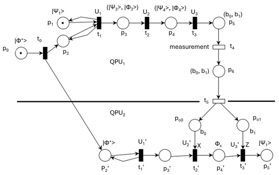
Figure 1.
QPN model for teleportation.
The circles represent PN places that correspond to state elements. The information assigned to places composes the PN marking that models the state of the system. The transitions model the system’s state changes performed by the assigned operations. Filled rectangles represent quantum operations, while empty rectangles correspond to classical operations. Places , and are classical, while the rest of the places are quantum. Places and model measurements of quantum places and , respectively.
The vector information to send is , and the Bell state is .
They are used for the transition mappings providing the vectors
The previous model of teleportation can be reduced by joining sequential transitions. The simplified version is represented in Figure 2. The two entangled states stored in and containing the vector are used as support for teleportation of the vector stored in . The system relevant initial state is given by the marking . Almost instantly, the quantum system state becomes , but only after the execution of the classical transition and the sending of the classical bits to , the vector is teleported. The teleportation is consistent only if the classical transmission is performed during the coherence time interval of .
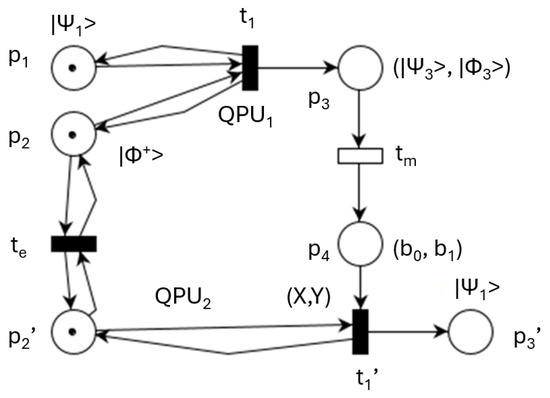
Figure 2.
Simplified QPN model of teleportation.
Table 1 shows the meanings and sizes of nodes and the involved operations for the QPN model shown in Figure 2.

Table 1.
Node significance of Figure 1 model.
The bidirectional communication between and is shown in Figure 3. This model performs and .
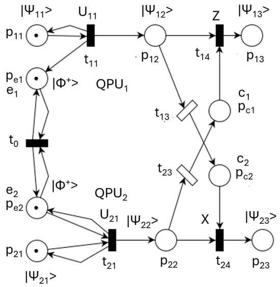
Figure 3.
QPN model for double communication.
The double communication is timed by classical transitions and , which include the qubit measurements and their transmissions.
Places and model quantum communications channels denoted by and , respectively. Places and model classical channels and , respectively. They control the behavior of quantum gates modeled by transitions and .
2.5. Analysis and Verification of Quantum and Classical Petri Nets
PNs are bipartite oriented graphs composed of nodes that model the states (represented by places) and their changes (described by transitions). Classical tasks are implemented by digital bits and classical logic circuits that execute logic or arithmetic operations.
Usually, quantum applications are composed of cooperating classical and quantum tasks. Classical tasks solve the user interface, set the quantum task parameters, and control the start and measurements of the quantum tasks. Quantum tasks implemented by discrete variables (i.e., qubits) or continuous variables (i.e., qumodes) change the physical process states by quantum circuits executing quantum operations. Concentrated or distributed quantum tasks evolve at a much higher speed relative to their counterpart classical components.
Verification and analysis of PNs are often performed by Petri Net-based Language and reachability graphs. These methods were used in the current research study.
The behavior of Classical or Quantum Petri Nets, as well as the relations between these two kinds of PNs, must be analyzed and verified.
Petri Net-Based Language (PNL)
This method describes the execution of parallel, sequential, and concurrent transitions. It can also be used for Classical PNs or Quantum PNs. Using the notations “*” for sequence, “+” for alternative, for concurrence, and for closing a loop, the behavior of a PN can be described. For example,
- describes the sequential execution of transitions and ;
- describes the alternative for executing transition or ;
- describes concurrent execution;
- describes a loop .
Details of their use are provided in [47,48]. PNL can be extended for Enhanced Time Petri Nets (ETPNs) obtaining a language (ETPNL) capable of describing dynamic open system behavior.
DQCPNs include quantum task models and classical task models that behave in different domains and interact through clearly defined and modeled frontiers separating them. Both kinds of tasks are modeled by PN-based templates. PN-based Language can describe concurrency and can be used to determine the precedence relations. Enhanced (Time) PN-based Language can include input events and signal output events linked to their frontiers.
Enhanced (Time) Petri Net-based Language can be defined in the following manner: Time is a classical task feature, while quantum tasks lack it, so EPNL notation should be used for quantum program description. The precedence notation corresponding to transitions is endowed with two parameters, and , representing external input and output events, respectively, becoming . These events are included in quantum or classical places according to the specification. When one or both events are missing, this is marked by the symbol “-”.
The entanglement sequence is
Transitions and are externally controlled without the controls represented in Figure 3. Classical transitions can be delayed by clock ticks, which are kinds of external time input events.
2.6. Reachability Graphs
The execution of transitions changes the states of classical and quantum components. The Classical or Quantum PNs states are represented by markings. Reachability graphs are used to determine the markings that can be reached during program execution. A reachability graph analysis approach can be used to determine and enforce the desired control requirement for a composed classical quantum model.
Some sequences of transitions provide cyclic behaviors, while others determine acyclic behaviors. The interface(s) between classical and quantum tasks creates a frontier that must be analyzed for quantum-centric application verification.
Unlike bounded numerical PNs, where the state numbers are finite, the current approach involves infinite numbers of states for classical and quantum parts. As a consequence, the term state label is more appropriate for the reached markings than reached states.
In qubit implementation, the state is considered its probability on the basic axis. In qumode implementation, the physical state is defined by the photons’ position and momentum. The vector is used as the quantum program state, a replacement of the real physical state.
3. Materials and Methods
Distributed quantum-centric applications are composed of classical parts and quantum parts. In the current approach, the classical parts are modeled by OETPNs and the quantum parts by QPNs. All components must cooperate to fulfill the specifications and the requirements of the application.
3.1. Parameterized Quantum Circuits (PQCs)
A unitary matrix can be parameterized by a parameter [23]. This performs the relation
A classical part of a quantum-centric computing program provides the parameter . The model shown in Figure 4 starts from the initial quantum state and the classical state .
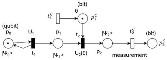
Figure 4.
QPU and classical interface.
Typically, is the initial state obtained from n qubits, each in state , forming the product state . In some cases, the required initial state is obtained by multiplying by a unitary matrix.
Changing the variational parameters while a QPU executes a quantum program modifies its quantum state.
The quantum part state is . When the quantum program begins, its state changes instantly to . The mapping reloads place with the initial value in an ideal QPU (with I being the identity matrix). In a real QPU, however, noise leads to the relation , where represents the noise effect in time and is the practical approximation of the resulting unitary matrix that replaces the ideal I matrix. If the quantum program interacts with a classical program, their interaction must occur within the quantum fidelity period.
The execution of classical transition results in
The execution of before provides the measurement v of . Conversely, if is executed first, the measurement of is provided.
As was shown, a quantum program model can describe the joining of qubit vectors (e.g., transitions or in Figure 3) or split the qubit vector (e.g., transitions and or and in Figure 3). The split qubits (or vectors) can be measured separately during quantum program execution. Consequently, the place sizes or the token sizes that can be set in a place may vary depending on the developer’s needs.
3.2. QPN Models with Qumodes
Our earlier QPN models were based on discrete qubits in Hilbert space. In these models, places store quantum states using V vectors of dimension m and/or vectors of dimension . State evolution is modeled by transitions performing unitary operations either on individual qubits or collectively on multiple qubits.
The current approach extends the previous definition of QPNs to include one or both types of quantum variables: discrete qubits and qumodes. The V vectors can consist of qumodes or, collectively, multi-qumodes. In this case, Hilbert space is replaced by Fock space, and the unitary operations are adjusted accordingly. As mentioned earlier, cutoff dimensions must be introduced, which set the size of multi-qumodes to .
The equivalent qubit parameterized unitary matrix for a qumode can be obtained by a sequence of displacement and rotation .
The overall structure of QPN models remains the same, as do the sequences of transitions describing the evolution. In the case of discrete qubits, measurement often requires multiple shots, whereas for qumodes, a single shot is sufficient.
3.3. Temporal Analysis of DQCPN Model
A temporal analysis should verify the state changes of the quantum program in relation to its interaction with the classical program. Consider the double communication program shown in Figure 3. The initial states of are
According to the Classical Petri Net principle of atomic transitions, transitions and cannot occur simultaneously. They are concurrent; therefore, their corresponding events are ordered by the “happen before” relation represented by : either or . The QPN reachability graph contains the states
and
before reaching the final state
Both measuring events must occur within the fidelity periods of the QPUs to ensure computational correctness.
The partial ordering involved in entanglement in quantum programs can be determined by inference of EPNL relations. So, the construction of reachability graphs can be obtained under the constraints given by EPNL. Due to the entanglement requirement, the constraint must be implemented for Figure 3.
A quantum-centric program consists of a QPN and a Classical Petri Net, modeled here by OETPN. The interface between the QPN and the OETPN includes classical control places and classical measurement places.
3.4. QPN Definition
Figure 5 illustrates a QPN model composed of four places and a transition. The places represented by circles model the system state described either by a Hilbert vector denoted by or by an array of qubits or qumodes denoted by V, as shown in Figure 6.
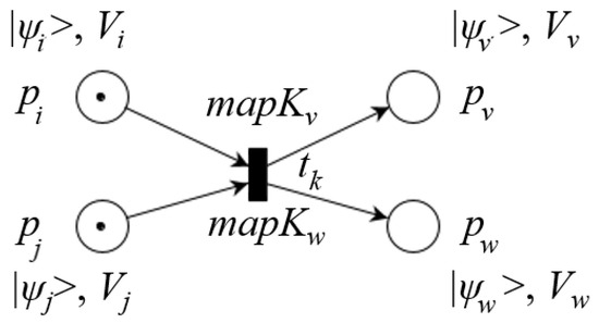
Figure 5.
QPN representation.
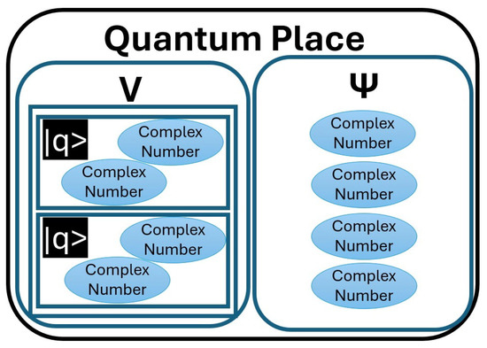
Figure 6.
Quantum place representation.
A vector can be converted into the corresponding vector by the relation
System change is performed by transitions, denoted here by , which modify the states of the system. When particular qubits or qumodes of a vector are involved, the corresponding mappings are marked on the arcs. A descriptive representation can be seen in Figure 7.
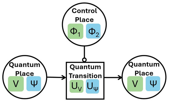
Figure 7.
Quantum Petri Net representation.
If the detailed relations performed on qubits or qumodes composing a vector V are
these lead to a new vector . The corresponding vector can be directly determined by a composed unitary matrix U given by
When the unitary matrices depend on parameters, they can be provided by control places. For example, a rotation angle may be used in a unitary matrix through sine and cosine functions, yielding .
In this approach, the mappings multiply the input tokens stored in the transition input places by unitary matrices. More details are given in [24].
The formal definition of is
where the following apply:
- N = (P, T, F) is a bipartite oriented graph (i.e., net with two disjoint sets of nodes).
- is a finite set of places, with .
- is a finite set of transitions, with .
- is the flow relation.
- is a vector containing the sizes of the vectors ) stored in the corresponding places; for qumodes, the cutoff dimensions must be included.
- is a set of input channels providing the parameters of unitary matrices.
- is a set of output channels providing the measurements of some qubits.
- is the set of mappings (i.e., pair ) assigned to arcs linking the transitions with places; if one of them is missing, it is denoted by .
- is a matrix with initialized values (i.e., the initial quantum superposed states).
- init is the initialization method.
- end is the stop method.
- is a matrix storing the values of the final quantum superposed state (i.e., the result matrix).
Some important relations related to QPNs are
- °t describes the transition t input place set;
- describes the transition t output place set.
QPN tokens are quantum superposed vectors stored in places and transformed by transitions implementing unitary matrices. Let and be two vectors in Hilbert space or Fock space. Then,
Above, A is a matrix that generates a transformation of a quantum superposed state. , where is the conjugate transpose of A. Such matrix A is called unitary. This property of A guarantees that the transformation with is valid. For simplicity reasons, only particular cases of unitary matrices are used in this work.
Similar quantum operations can also be defined for qumodes and multi-qumodes.
3.5. Quantum Tasks with Repeated Operation Execution
Figure 8 shows a theoretical QPN model that requires the periodic execution of operations and , followed by transition , which measures the state of . The model contains conflicting transitions and . The decision whether to continue the quantum process or to stop it and measure place is difficult to implement. Another challenge is to change the state of place .
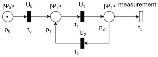
Figure 8.
Theoretical repeated quantum task execution.
Until quantum technology permits the modification of a quantum register qubit (currently forbidden by the no-cloning principle), the model shown in Figure 9 can be used. The number of times n that the operations and are executed is fixed and predefined.

Figure 9.
Practical repeated quantum task execution.
3.6. Quantum Iterative Task Execution
Some applications, like machine learning, require the iterative execution of quantum tasks with different parameters. Figure 10 displays a quantum task that executes the operations modeled by transitions and dependent by the parameters and set by a classical task. For a two-qubit register, an example of is

Figure 10.
External controlled quantum task execution.
This operation rotates the first qubit by an angle determined by the parameter used to set the QLC assigned to transition . In an iterative execution, the parameters and the QLCs are set before the quantum task begins.
3.7. Distributed Quantum-Centric Petri Nets (DQCPN)
A DQCPN model consists of cooperating QPNs and OETPNs. A QPN has quantum places and transitions , while an OETPN has classical places and transitions . OETPN models can be distributed and implemented on a classical computer network, while QPNs can be distributed and implemented on a set of cooperating QPUs. OETPNs and QPNs can interact through quantum–classical interfaces:
where
Here and represent the numbers of QPU components and OETPN components, respectively.
The interface between two QPNs contains quantum transitions that implement entangled quantum places. Classical places and classical transitions compose the interfaces between two OETPNs. The frontier between a QPU and a classical computing component is represented by classical places, while the quantum–classical interface is implemented by measuring transitions of quantum places.
3.8. Quantum Processor Unit (QPU) Model
Figure 11 displays the generic template of a quantum task implemented on a Quantum Processor Unit. The node specifications are as follows:
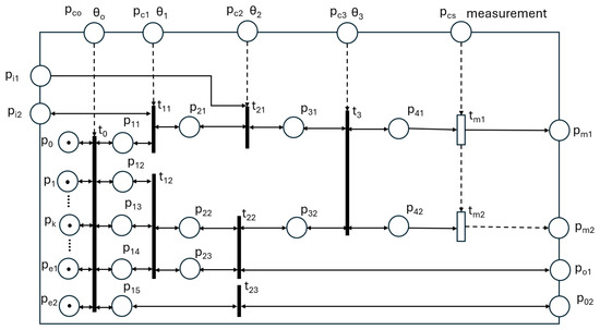
Figure 11.
Generic template of quantum task.
- Input quantum places: and .
- Output quantum places: and .
- Internal initial places (corresponding to internal qubits): Their type is quantum.
- Entangled qubits places: and . Their type is quantum.
- Measured places (qubits): and . Their type is classical vector.
- Control places: , , , and . Their type is classical vector. They can be used to set QLC parameters or for the selection of QLCs.
- Measurement control places: . There can be multiple classical measurement control places.
- Transition parameters: and . These determine the unitary matrices performed by transitions. They are classical vectors and define the types or behaviors of the involved unitary matrices.
Execution of a program built using this template is performed under the following assumptions:
- No noise is present; thus, the quantum process can last as long as necessary.
- Transitions are executed under the All at Once principle.
- Once a stable state is reached, it can be changed by the control places or by changes in input places’ states, leading to another stable state.
- Quantum measurements do not stop the QPU process.
- Classical measurements stop the measured qubit but not the unmeasured qubits.
- A complex quantum program can be implemented on more QPUs by linking their input and output places. Each QPU executes a quantum task, and the set of quantum tasks run concurrently.
3.9. QPN Model of a Quantum Task
A quantum program is composed of a set of distributed, concurrent, and communicating quantum tasks. Typically, each quantum task is deployed on a QPU; however, this is not mandatory—multiple tasks can be implemented on the same QPU.
The model of a quantum task is composed of the tuple
where the following apply:
- N = (P, T, F) is the earlier defined net (Section 3.4).
- is the earlier defined vector (Section 3.4).
- is a mapping assigning types to places: .
- is a set of unitary matrices corresponding to quantum logic circuits available in the QPU, which can be assigned to transitions through the mapping .
- is a set of qubits or qumodes (usually initialized in the quantum state ).
- is a set of input places receiving quantum vector information from other quantum tasks (QPUs).
- is a set of input control places used for transition control. They contain parameters from the set used in the transition unitary matrices.
- is a set of output places used for sending quantum vectors to other quantum tasks (i.e., QPUs).
- is a set of measurement places that store classical information from measured qubits or qumodes for output QPU use.
- is a set of controlled transitions used to measure their input places, storing the information in as either quantum or classical type.
A quantum task begins when control place receives parameters. The enabled transitions, conventionally partitioned in steps, are executed. The quantum task reaches a balanced state that persists until one of the input places from receives an event that changes its state (Algorithm 1).
| Algorithm 1 QPU or quantum task executor |
|
3.10. Optimization of DSs
A quantum approach of combinatorial problems is based on the Quantum Approximate Optimization Algorithm (QAOA) [49]. Dynamic optimization problems with continuous variables are more challenging, particularly in open systems.
Variational Quantum Algorithms (VQAs), frequently used for optimization, are hybrid algorithms that employ both quantum and classical computing to find approximate solutions. These can be either gradient-based or gradient-free methods [30].
Evolutionary Systems (ESs) and their extensions Quantum Evolutionary Systems (QESs) are also commonly used in DS optimization. More details are given in [24].
Genetic Algorithms (GAs) and Quantum Genetic Algorithms (QGAs) are based on individuals grouped into populations that are iteratively improved using performance evaluations [50].
Unlike GAs, QGAs require the quantum implementation of individuals and the execution of genetic operations such as mutation, permutation, crossover, and combination. These operations can be efficiently implemented and controlled on a quantum computer (QC) or a QPU. Performance-based individual selection increases the chance of choosing better candidates. Performance evaluation requires adding unitary vectors multiplied by sub-unitary coefficients, which can be implemented through a unitary matrix applied to output variables.
For optimal control, Particle Swarm Optimization (PSO) has been used. A historical perspective on PSO development is given in [51].
PSO is a metaheuristic global optimization paradigm valued for its ease of application to complex multi-dimensional problems unsolvable by traditional deterministic algorithms [51,52]. Various methods have been developed to avoid local optima and improve search speed. Applications of PSO in multiple fields are analyzed in [53].
A quantum variant, Quantum Particle Swarm Optimization (QPSO), is described in [54,55,56]. Both classical PSO and QPSO benefit from features inspired by natural organisms. PSO models particles as moving in Newtonian space, characterized by position and velocity [52].
PSO has been enhanced with quantum features, yielding QPSO [55]. Quantum entanglement has been incorporated for quantum-inspired PSO [57]. Cooperative swarm intelligence is another application of QPSO [57]. QPSO can also be applied successfully to multi-task problems [58].
4. Experiments
As an application of DQCPNs, an Urban Vehicle Traffic Control (UVTC) system is chosen. Links between quantum computing and traffic management can be found in [59].
According to [60], a key component for the study and development of intelligent transportation systems is traffic modeling, which provides a framework for better investigating and testing the state of the road in real time and accurately predicting future traffic. Colored Petri Nets and Complex Event Processing are used for this purpose, representing the modeling of the city map and its vehicle traffic. Remarkably, here, the scalability challenge can be addressed by classical (Colored) Petri Nets, so their extension to QPNs is expected to also retain this feature.
The proposed QPN is a distinct type of PN model that retains most of the PN features. Supervised machine learning requires model training, where the high speed of quantum simulations constitutes a relevant benefit. The DQCPN approach supports the distributed implementation of UVTS, as well as model training.
The Urban Vehicle Traffic System (UVTS) is a modern and complex problem involving variations in traffic flow that require timely reactions under temporal constraints [61]. The UVTS can be described as vehicle flows that vary probabilistically in space and time [62]. Traffic flow parameters can be changed and controlled at intersections.
The current approach considers a network of simple intersections with two phases of controllable duration. The template of such an intersection is shown in Figure 12, where for direction i , the flow states are denoted by , the input flows by , and the output flows by .
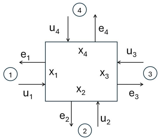
Figure 12.
Single crossroad template.
The relations describing the dynamics of the intersection in Figure 12 consist of incoming flows, internal flows, and outgoing exit flows. An incoming input flow in iteration k is split into two directions, and , as
according to the split coefficient of input flow at time k.
The intersection flows are controlled by a signal , with and representing phase duration parameters. All intersections are assigned the same cycle duration.
The flows for the horizontal directions (modulo 4) in iteration k are described by
where is the flow state at time k and is the exit flow. The notation means the minimum of a and b.
The flows for the vertical directions (modulo 4) in iteration k are described by
Exit flows are constrained by a value representing the maximum lane exit capacity:
An UVTS composed of four intersections, , and , is shown in Figure 13. This system is used for optimal control with the goal of achieving maximum throughput.
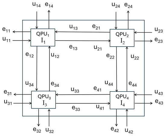
Figure 13.
Urban vehicle traffic structure.
Each intersection has two input flows () and two output flows () coming from or going outside the controlled area. Here is used for horizontal flows and for vertical flows.
The incoming flows in the system () may vary, but the control system modifies control () such that the UVTS achieves the highest possible throughput, for the current demands, as assessed by
For simplicity, the input flow splits () are considered constant.
The flows of the UVTS model can be implemented by QPNs using different types of places and their corresponding transitions:
- Single qubits in Hilbert space with multiple shots;
- Multi-qubits (discrete) in Hilbert space with a single shot;
- Single qumodes in Fock space with a single shot;
- Multi-qumodes in Fock space with a single shot.
In this approach, each QPU implements an intersection, and the entire UVTS is implemented in four linked QPUs.
An input flow split into and according to a parameter set in control place is represented in Figure 14.
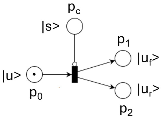
Figure 14.
Input flow split QPN model.
Figure 15 shows the QPN model representing the exit flow , composed of the previous flow (), the forward input flow (), and the right input flow ().
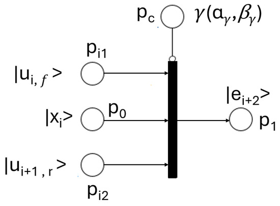
Figure 15.
Exit flow QPN model.
By combining these components, the QPN model shown in Figure 16 is obtained. Place represents the initial value of a qubit or qumode. It is used by the mapping assigned to for setting in the initial value of , according to the value loaded in . Place receives the input value , which is split by transition according to the split value set in place . A similar role is played by nodes , and .
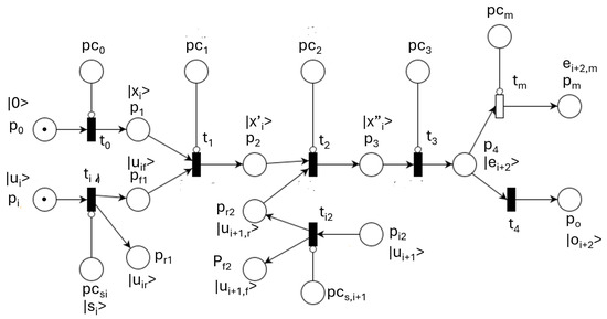
Figure 16.
QPN model of one-lane flows.
Transitions and model the increase in flow by the input flow in phases one and two, respectively. The increase values are set in and . Transition models the exit flow stored in , measured by , and sent forward by . The time when the exit flow is measured is controlled by place .
The execution of the above QPN model can be divided in steps:
- Step 1 executes concurrently transitions and , producing flows , , , , and .
- Step 2 executes transition , increasing flow with when phase 1 is open.
- Step 3 executes transition , which adds right flow during phase 2.
- Step 4 executes transition , releasing the vehicle flow to the next intersection or out of the system.
- Step 5 models the exit flow by transition and place .
Finally, transition is executed, and exit flows are measured.
4.1. Lane Flows: Implementation and Simulation
Quantum model implementation and simulation of UVTSs can be performed using either discrete variables or continuous variables for flow modeling. Discrete variables can be implemented with one qubit per flow or with multiple qubits per flow. In the latter approach, the time for performing arithmetic operations (see [63]) can be utilized in the classical style. Another approach is based on qumodes, using one qumode per flow or multiple qumodes per flow.
4.1.1. One-Qubit-per-Flow Implementation
Each of the flows mentioned above is implemented by one qubit. Instead of the well-known Bloch sphere, the qubit is represented on a circle. Figure 17 illustrates a qubit constrained to a circle (plane) described by
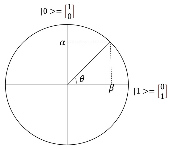
Figure 17.
Polar plot of a qubit.
The qubit measurement is obtained by projecting it onto the axis. Multiple execution shots are required to obtain reliable flow measurements. A mapping from the flow domain to the qubit measurement domain converts a flow variable into a qubit, or vice versa. For example, a flow range of vehicles/minute corresponds to the qubit measurement range .
For the input split model shown in Figure 14, an implementation based on one qubit per flow is proposed, as illustrated in Figure 18. It describes a qubit that controls two entangled inputs and , defined by the pair and , where .
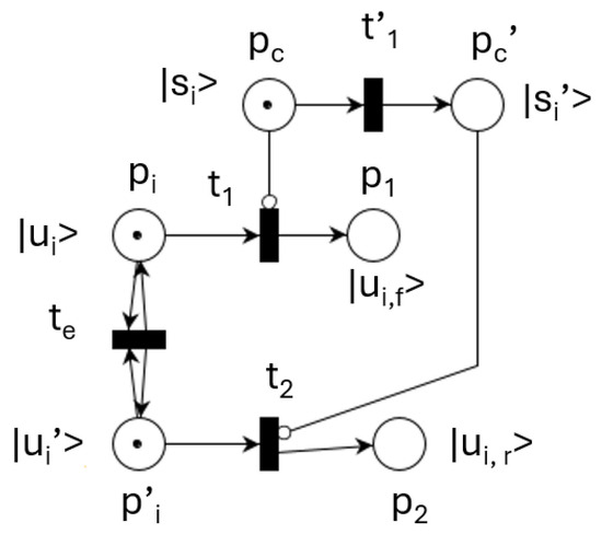
Figure 18.
Implementation of input flow split QPN model.
The model shown in Figure 14 was practically implemented based on the relations
with the split flows being given by
Using the split relations and , the rotation angles and can be determined:
A lane exit flow opposite entrance i is determined by the relations
with and taken from modulo 4. An exit flow from one intersection becomes the input flow of the next. Assuming that a phase is open when and closed when , the coefficients and determine the entrance and exit of the lanes.
In Figure 16, the input splits are controlled by and , while the crossings are controlled by and . The rotation angles of transitions and are
Place is initialized to , and transition , controlled by place , injects into place the initial value of flow state . Input place receives the split value . Transition , controlled by place , sets the qubit in place , representing the sum of the two previous qubits. The input value is added to , controlled by the state of . It is assumed that enters during phase one on and during phase two on . The exiting vehicle flow of a lane, with state , is modeled by transition . Vehicles exit in both phases, represented by and . The rotation angle of transition is fixed and identical for all flows moving forward, denoted by .
4.1.2. Multi-Qubits-per-Flow Implementation
Using four qubits to represent a vehicle flow can cover the range vehicles/minute. The number of times these operations are applied is set in the control places , and .
4.1.3. One-Qumode-per-Flow Implementation
A qumode can represent a vehicle flow if a scaling function is applied.
Let of dimension 8 be a variable modeling a vehicle flow , and let be a function that converts the measured value into the corresponding flow by the relation
The initialization of flow corresponds to a qumode value , obtained as
The parameters and can be determined using Particle Swarm Optimization (PSO) or a Genetic Algorithm (GA) so that the resulting qumode is an acceptable approximation of (i.e., ).
The input flow split can be simulated using two entangled qumodes. A beamsplitter gate provides two exit qumodes that are separately rotated, one in the positive direction and the other in the negative direction.
Flow addition or subtraction can be simulated by positive or negative displacement and rotation, respectively.
In conclusion, using qumodes does not require changing the implementation logic. Only the mappings assigned to transitions must be modified for qumode operations.
4.2. Intersection Model
By joining the flow inputs in a vector U, the lane flow states in a vector X, the lane exits in a vector E, and the phase controls of the two phases, the composed (concentrated) QPN model of the QPU that integrates the crossroad is obtained. These vectors correspond to the relations
The vector describes the split input vector containing pairs for . Some exit flows are measured, and some outputs of an intersection are linked to inputs of other intersections.
For practical reasons, the qubit implementation was performed using V vectors instead of vectors. Detailing the two phases and representing separately the input vehicle flows used in the second phase by , the QPN model of all four lanes integrated into an intersection is shown in Figure 19.
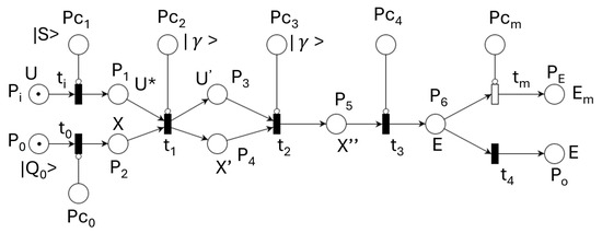
Figure 19.
QPN model of an intersection.
Each QPU integrates the QPN model of an UVTS intersection. The vectors of an intersection’s four lanes are denoted by and . Place integrates four qubits initialized at . Controlled transition sets in place state .
Input place receives four qubits , which are split by transition according to the split values provided by place . Thus, place contains eight qubits .
Some of these inputs are used by controlled transition (modeling phase 1), while the other four are used by transition (phase 2). Both phases are controlled by places and , which store the control qubit . Transition models the four exit flows. These are measured by transition and sent out through transition via place .
The intersection model can be implemented with either four qubits per vehicle flow or one qumode per vehicle flow. The vectors and the operations assigned to transitions must be adapted accordingly.
4.3. UVTS QPN Model
Figure 20 displays a QPN model integrating the QPN models of all four intersections. If the previous vectors are joined according to their roles, we obtain the vectors of the QPN model corresponding to the entire UVTC system. They are denoted by
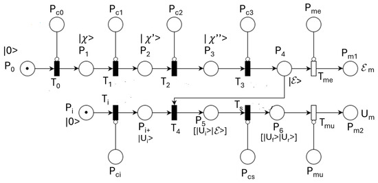
Figure 20.
QPN model of UVTC system.
The qubits or qumodes initialized in place at state are mapped by controlled transition into place , according to the required states , transmitted through place . Place is initialized at for all four qubits, vectors of qubits, or qumodes.
Transition sets in the external inputs according to the information received through place . The internal inputs stored in (i.e., ) are provided by transition from the exit flow lanes.
Transition splits the input flows, storing them in place , denoted by . Transition models phase 1 of all intersections, while models the opposite phases. Transition models the lane exits of all intersections. Transition models the feedback of exit flows converted into internal input flows. links the exit flows with the corresponding input flows according to the UVT topology depicted in Figure 13.
Information stored in place can be measured at the request of the classical component.
Table 2 shows the nodes, their sizes, and the operations involved for the one-qubit-per-flow implementation. It can be extended for the four-qubits-per-flow or one-qumode-per-flow implementations.

Table 2.
Node significance for one qubit per flow of Figure 20 model.
Figure 21 shows the architecture of the distributed quantum-centric application solving the optimal control of the UVT problem. The classical computing components receive the inputs , the current flow states , and the input splits S of U. These are sent to the control component, which fills the control places of the QPUs. An initial control set is also provided. The quantum computing process is then started. After a specified delay, Control measures exit lane flows , which are used to compute input splits and lane exit flows.
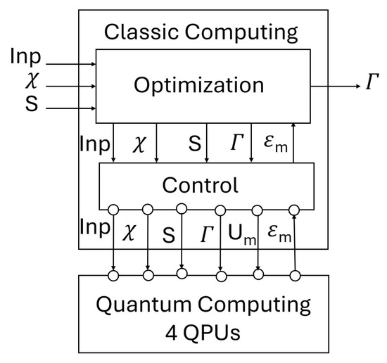
Figure 21.
Component diagram of quantum-centric system.
The optimization component finds control by using the measured values . The control problem of UVT with QPN models consists of finding intersection phase controls for a given initial flow , input splits , and input demand flows such that the highest throughput (see Equation (54)) is achieved.
The optimization problem was solved using the Particle Swarm Optimization (PSO) algorithm and the Genetic Algorithm (GA), with comparable results. A GA individual or PSO particle represents the vector .
The current problem reduces to finding the phase control vector
That is, finding in a four-dimensional search space.
The Quantum Computing System (QCS) reaches the initial equilibrium state by executing the sequence
During an experimental scenario, the inputs and the control are fixed, leading the system to states for , converging to equilibrium states . The QCS then performs the relation .
The classical control component implements the Algorithm 2:
| Algorithm 2 Classical control |
|
A mapping is used to convert the output flows into input flows of neighbor intersections.
Being a hybrid implementation, the reachability graph must contain both classical and quantum states. The marking is , where
and
The reachability graph of the hybrid implementation can be expressed as , where the superscript denotes the iteration.
The QPN model of the UVTS can be implemented using either discrete or continuous variables, as described in [22]. A discrete-variable QPN was used in [24].
4.4. Dynamic System Optimal Control
The Evolutionary System (GA or PSO) used for heuristic optimization has the role of finding optimal control of the UVTS in state for given and split S. It implements the Algorithm 3:
| Algorithm 3 Evolutionary system |
|
4.5. Experimental Results
The experiments were partitioned into three scenarios starting from initial flow state and applying three vectors of outside inputs:
- Scenario 1: UVTS cycles 0 to 6.
- Scenario 2: UVTS cycles 7 to 11.
- Scenario 3: UVTS cycles 12 to 17.
All the input splits were .
Figure 22, Figure 23, Figure 24 and Figure 25 display the evolution of flow of intersection . The other flows have similar evolution. For one qubit per flow or one qumode per flow, a scale factor of 15 is used to obtain the real value of the vehicle number per minute.
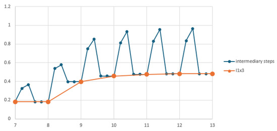
Figure 22.
One-qubit-per-flow lane simulation.
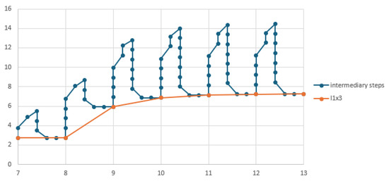
Figure 23.
Four-qubit-per-flow lane simulation.
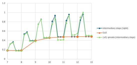
Figure 24.
One-qumode-per-flow lane simulation.
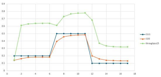
Figure 25.
Flow evolution of controlled UVTS.
The lane modeled by one qubit per flow is displayed for Scenario 2 in Figure 22. The orange curve shows flow at the end of each cycle, while the blue curve represents its values at intermediate steps. The initial state was . The input sequences for the six cycles were and . The phase controls of the four intersections were .
The lane modeled by four qubits per flow is displayed for Scenario 2 in Figure 23. The red curve shows at the end of each cycle, while the blue curve represents intermediate values. The initial state was . The input sequences were and , with .
The lane modeled by one qumode per flow is displayed for Scenario 2 in Figure 24. The goal was to replicate the same evolution obtained with one qubit per flow. While the qubit implementation uses the rotation gate , the qumode implementation applies a displacement followed by . The values of and were determined using PSO and GA, minimizing at each cycle the deviation , where is the qumode-based flow and is the qubit-based flow. The total fitness fraction assessing the deviation between qubit and qumode simulations was 0.2098.
Figure 24 shows the qumode-based lane simulation in gray, with the corresponding qubit-based simulation in blue. The input sequences, initial state, and controls were identical to those of the qubit simulation.
Table 3 shows the pairs of parameters used for displacement and rotation in each QPN step of vehicle traffic simulation.

Table 3.
Quantum operation parameters for qumode simulation.
Figure 25 shows the evolution of the controlled UVTS: blue for input evolution, orange for lane flow evolution, and green for throughput. UVTS throughput was divided by 5 to use the same vertical axis.
UVTS throughput was analyzed under three input vectors:
- ;
- ;
- .
Table 4 summarizes the results obtained using the GA and PSO methods.

Table 4.
Optimal control parameters.
5. Discussion
The proposed approach uses general quantum gates, ignoring the logical quantum circuit synthesis and the involved compilation and transpilation processes. We are aware that the performance of quantum computers depends not only on the necessary physical qubits or qumodes but also on the gate error rates, which were not subjects of the current research study. According to [4], the classical processors work synergistically with quantum processors for generating control logic, providing storage and networking services at runtime. The application quality depends on the classical software and how it is linked to quantum software.
Solving a problem starts with its specification, and after its analysis, an algorithm or a set of algorithms is deduced. Some functions are determined that must be implemented on Quantum and Classical Processing Units. Which of them have to be implemented on QC and which on CC constitutes a question that the developer must answer. QC implementation benefits from the opportunity to quickly obtain the solution to some complex problem that must obey real-time requirements. The feasibility analysis would provide the answer if the required architecture met the expected results.
In the above-mentioned reference, quantum temporal cohesion is defined as executing an operation on multiple qubits in the same time span. Quantum spatial cohesion is assessed by the existence of a correlation between neighboring qubits that interact. Quantum coupling is assessed by the degree of interdependence between different modules that affect the interface of the relevant components. The current approach considers a mixed quantum and classical implementation of distributed complex applications, so temporal and spatial coherence should be assessed by the involved QPUs cooperating with classical components. A similar assessment should be used for mixed coupled components.
The verification of quantum-centric applications involves the verification of the quantum parts and the classical parts, as well as their interactions. Besides the state space dimensions, which are usually large, there is an explosion of state space size that makes the direct verification of all the possible reachable states impossible. Using some state labels having kinds of shared features or common links can lead to affordable verification methods. The inherent quantum randomness can be included in the state representatives. Even some precedence relations can be defined and analyzed in relation to sets of concurrent quantum and classical operations.
All the implementations are affected by quantum execution errors. The desired precision determines the number of necessary experiments. The precision assessment must begin with the sequence of the transitions that are executed and the precision of the operations involved. For example, the sequence for reaching the initial equilibrium state of the UVTS (see Equation 70) provides the operations that are executed. Their precision depends on the quantum computer that executes these operations.
6. Conclusions
The goal of unitary development of quantum-centric software using a qubit-based or qumode-based approach mixed with classical computing components was attained. The proposed example for experiments shows a similarity of information flows and vehicle flows. Also, both must be controlled to reach the goals. There is a common view/model for one qubit per flow of information/vehicles, multi-qubits per flow of information/vehicles, or one qumode per flow of information/vehicles. The same graph can be used for the construction of different models of computation. Developers can decide which kinds of information flows are most suitable for their applications. The PNs can be extended and adapted for catching the quantum and classical states, as well as the necessary operations and interactions. They can display the details at different levels and so facilitate development processes.
The QPU pattern helps the quantum implementation of distributed software and the control of quantum processing. The partitioning of applications on quantum tasks and classical tasks facilitates the design, the functions deployment and their behavior verification.
Author Contributions
Conceptualization, T.S.L.; Methodology, T.S.L., I.M. and O.C.; Software, C.A., D.A.-J. and O.C.; Validation, I.M. and O.C.; Formal analysis, T.S.L. and I.M.; Investigation, D.A.-J.; Resources, O.C.; Visualization, D.A.-J.; Supervision, C.A. All authors have read and agreed to the published version of the manuscript.
Funding
This research received no external funding.
Data Availability Statement
The data presented in this study are openly available on GitHub using QPN-v2.0. at https://github.com/dahliajanabi/QPN-v2.0 (accessed on 28 August 2025).
Conflicts of Interest
The authors declare no conflicts of interest.
Abbreviations
The following abbreviations are used in this manuscript:
| QC | Quantum computation or computer |
| CC | Classical computation or computer |
| DQ-CC | Distributed Quantum-Centric Computing |
| PN | Petri Net |
| OETPN | Object Enhanced Time Petri Net |
| PNL | Petri Net based Language |
| QPN | Quantum Petri Net |
| EA | Evolutionary Algorithm |
| QEA | Quantum Evolutionary Algorithm |
| PSO | Particle Swarm Optimization |
| QPSO | Quantum Particle Swarm Optimization |
| GA | Genetic Algorithm |
| CGA | Classical Genetic Algorithm |
| QGA | Quantum Genetic Algorithm |
| QIGA | Quantum-Inspired Genetic Algorithm |
| QAOA | Quantum Approximate Optimization Algorithm |
| ES | Evolutionary System |
| QES | Quantum Evolutionary System |
| QPU | Quantum Processing Unit |
References
- Dutta, R.; Allen, B.; Vu, N.P.; Xu, C.; Liu, K.; Miao, F.; Wang, B.; Surana, A.; Wang, C.; Ding, Y.; et al. Solving Constrained Optimization Problems Using Hybrid Qubit-Qumode Quantum Devices. arXiv 2025, arXiv:2501.11735v1. [Google Scholar] [CrossRef]
- Abbas, A.; Ambainis, A.; Augustino, B.; Bärtschi, A.; Buhrman, H.; Coffrin, C.; Cortiana, G.; Dunjko, V.; Egger, D.J.; Elmegreen, B.G.; et al. Quantum Optimization: Potential, Challenges, and the Path Forward. Nat. Rev. Phys. 2024, 6, 718–735. [Google Scholar] [CrossRef]
- Serrano, M.A.; Cruz-Lemus, J.A.; Perez-Castillo, R.; Piatini, M. Quantum Software Components and Platforms: Overview and Quality Assessment. ACM Comput. Surv. 2022, 55, 1–31. [Google Scholar] [CrossRef]
- Dey, N.; Ghosh, M.; Samir kundu, S.; Chakrabarti, A. QDLC—The Quantum Development Life Cycle. arXiv 2020, arXiv:2010.08053v1. [Google Scholar] [CrossRef]
- Liu, S.; Wang, X.; Zhou, L.; Guan, J.; Li, Y.; He, Y.; Duan, R.; Ying, M. Q|SI⟩: A Quantum Programming Environment. In Symposium on Real-Time and Hybrid Systems; Lecture Notes in Computer Science, Article in Scientia Sinica Informationis; Springer International Publishing: Cham, Switzerland, 2017. [Google Scholar] [CrossRef]
- Jamous, K. Survey on Software Architecture for Quantum Computing: Design Principles, Challenges, and Future Directions. J. Theor. Appl. Inf. Technol. 2025, 103, 8. [Google Scholar]
- Khan, A.A.; Ahmad, A.; Waseem, M.; Liang, P.; Fahmideh, M.; Mikkonene, T.; Abrahamsson, P. Software Architecture for Quantum Computing Systems—A Systematic Review. J. Syst. Softw. 2023, 201, 111682. [Google Scholar] [CrossRef]
- Nguyen, T.; Santana, A.; Kharazi, T.; Claudino, D.; Finkel, H.; McCaskey, A.J. Extending C++ for Heterogeneous Quantum-Classical Computing. ACM Trans. Quantum Comput. 2021, 2, 1–36. [Google Scholar] [CrossRef]
- Svore, K.M.; Geller, A.; Troyer, M.; Azariah, J.; Granade, C.; Heim, B.; Kliuchnikov, V.; Mykhailova, M.; Paz, A.; Roetteler, M. Q#: Enabling scalable quantum computing and development with a high-level domain-specific language. In Proceedings of the RWDSL2018: Proceedings of the Real World Domain Specific Languages Workshop, Vienna, Austria, 24 February 2018. [Google Scholar]
- Moguel, E.; Rojol, J.; Valencia, D.; Berrocal, J.; Garcia-Alonso, J.; Murillo, J.M. Quantum service-oriented computing: Current landscape and challenges. Softw. Qual. J. 2022, 30, 983–1002. [Google Scholar] [CrossRef]
- Dunjko, V.; Briegel, H.J. Machine learning & artificial intelligence in the quantum domain. arXiv 2017, arXiv:1709.02779v1. [Google Scholar] [CrossRef]
- Brin, M.; Stuck, G. Introduction to Dynamical Systems; Cambridge University Press: Cambridge, UK, 2002; ISBN 0-511-02937-3. [Google Scholar]
- Adler, R.; Elberzhager, F.; Falcao, R.; Siebert, J. Defining and Researching “Dynamic Systems of Systems”. Software 2024, 3, 183–205. [Google Scholar] [CrossRef]
- Ghomori, L.; Alla, H. Modeling and Analysis using Hybrid Petri Nets. Nonlinear Anal. Hybrid Syst. 2007, 1, 141–153. [Google Scholar] [CrossRef]
- Isermann, R.; Munchhof, M. Identification of Dynamic Systems. In An Introduction with Applications; Springer: Berlin/Heidelberg, Germany, 2011; ISBN 978-3-540-78878-2. e-ISBN 978-3-540-78879-9. [Google Scholar] [CrossRef]
- Yua, R.; Wanga, R. Learning dynamical systems from data: An introduction to physics-guided deep learning. Proc. Natl. Acad. Sci. USA 2024, 121, e2311808121. [Google Scholar] [CrossRef]
- Wharton, K. Quantum States as Ordinary Information. Information 2014, 5, 190–208. [Google Scholar] [CrossRef]
- Liu, C.; Wang, M.; Stein, S.; Ding, Y.; Li, A. Quantum Memory: A Missing Piece in Quantum Computing Units. arXiv 2023, arXiv:2309.14432. [Google Scholar] [CrossRef]
- Lattner, C.; Amini, M.; Bondhugula, U.; Cohen, A.; Davis, A.; Pienaar, J.; Shpeisman, T.; Vasilache, V.; Zinenko, O. MLIR: Scaling Compiler Infrastructure for Domain Specific Computation. In Proceedings of the 2021 IEEE/ACM International Symposium on Code Generation and Optimization (CGO), Seoul, Republic of Korea, 27 February–3 March 2021. [Google Scholar] [CrossRef]
- Peduri, A.; Bhat, S. QSSA: An SSA-based IR for Quantum Computing. arXiv 2021, arXiv:2109.02409v1. [Google Scholar] [CrossRef]
- Lee, Y.; Boche, H.; Kutyniok, G. Computability of Optimizers. IEEE Trans. Inf. Theory 2023, 70, 2967–2983. [Google Scholar] [CrossRef]
- Choe, S. Quantum computing overview: Discrete vs. continuous variable models. arXiv 2022, arXiv:2206.07246. [Google Scholar] [CrossRef]
- Bharti, K.; Cervera-Lierta, A.; Ha Kyaw, T.; Haug, T.; Alperin-Lea, S.; Anand, A.; Degroote, M.; Heimonen, H.; Kottmann, J.S.; Menke, T.; et al. Noisy intermediate-scale quantum (NISQ) algorithm. Rev. Mod. Phys. 2021, 94, 015004. [Google Scholar] [CrossRef]
- Letia, T.S.; Durla-Pasca, E.M.; Al-Janabi, D.; Cuibus, O.P. Development of Evolutionary Systems Based on Quantum Petri Nets. Mathematics 2022, 10, 4404. [Google Scholar] [CrossRef]
- Letia, T.S.; Durla Pasca, E.M.; Al-Janabi, D.M. Quantum Petri Nets. In Proceedings of the 2021 25th International Conference on System Theory, Control and Computing (ICSTCC), Iasi, Romania, 20–23 October 2021; pp. 431–436. [Google Scholar] [CrossRef]
- Chandarana, P.; Paul, K.; Garcia-de-Andoin, M.; Ban, Y.; Sanz, M.; Chen, X. Photonic counterdiabatic quantum optimization algorithm. Commun. Phys. 2024, 7, 315. [Google Scholar] [CrossRef]
- Pfister, O. Continuous-variable quantum computing in the quantum optical frequency comb. J. Phys. B At. Mol. Opt. Phys. 2020, 53, 012001. [Google Scholar] [CrossRef]
- Choe, S.; Perkowski, M. Continuous Variable Quantum MNIST Classifiers—Classical-Quantum Hybrid Quantum Neural Networks. J. Quantum Inf. Sci. 2022, 12, 37–51. [Google Scholar] [CrossRef]
- Gu, M.; Weedbrook, C.; Menicucci, N.C.; Ralph, T.C.; van Loock, P. Quantum computing with continuous-variable clusters. Phys. Rev. A 2009, 79, 062318. [Google Scholar] [CrossRef]
- Kan, S.; Palma, M.; Du, Z.; Stein, S.A.; Liu, C.; Chen, J.; Li, A.; Mao, Y. Benchmarking Optimizers for Qumode State Preparation with Variational Quantum Algorithms. In Proceedings of the IEEE International Conference on Quantum Computing and Engineering (QCE), Montreal, QC, Canada, 15–20 September 2024. [Google Scholar] [CrossRef]
- Killoran, N.; Izaac, J.; Quesada, N.; Bergholm, V.; Amy, M.; Weedbrook., C. Strawberry Fields: A Software Platform for Photonic Quantum Computing. arXiv 2019, arXiv:1804.03159v2. [Google Scholar] [CrossRef]
- Cohren, L.; Bianchin, G.; Dall’Anese, E. Online Optimization of Dynamical Systems With Deep Learning Perception. IEEE Open J. Control. Syst. 2022, 1, 306–321. [Google Scholar] [CrossRef]
- Vazquez, A.C.; Tornow, C.; Riste, D.; Woerner, S.; Takita, M.; Egger, D.J. Scaling quantum computing with dynamic circuits. arXiv 2024, arXiv:2402.17833v1. [Google Scholar] [CrossRef]
- Au-Yeung, R.; B Camino, B.; Rathore, O.; Kendon, V. Quantum algorithms for scientific computing. Rep. Prog. Phys. 2024, 87, 116001. [Google Scholar] [CrossRef]
- Han, K.-H.; Kim, J.-W. Quantum-Inspired Evolutionary Algorithm for a Class of Combinatorial Optimization. IEEE Trans. Evol. Comput. 2002, 6, 6. [Google Scholar] [CrossRef]
- Patvardhan, C.; Bansal, S.; Srivastav, A. Quantum-Inspired Evolutionary Algorithm for difficult knapsack Problems. Memetic Comp. 2015, 7, 135–155. [Google Scholar] [CrossRef]
- Zhang, R.; Wang, Z.; Zhang, H. Quantum-Inspired Evolutionary Algorithm for Continuous Space Optimization Based on Multiple Chains Encoding Method of Quantum Bits. Math. Probl. Eng. 2014, 2014, 620325. [Google Scholar] [CrossRef]
- Bogdanov, Y.I.; Bogdanova, N.A.; Fastovets, D.V.; Lukichev, V.F. Quantum approach to the dynamical systems modeling. arXiv 2019, arXiv:1906.06410. [Google Scholar] [CrossRef]
- Wharton, K.B.; David, J.; Miller, D.J.; Price, H. Action Duality: A Constructive Principle for Quantum Foundations. Symmetry 2011, 3, 524–540. [Google Scholar] [CrossRef]
- Schmidt, H.W. How to Bake Quantum into Your Pet Petri Nets and Have Your Net Theory Too. In Symposium and Summer School on Service-Oriented Computing; Springer International Publishing: Cham, Switzerland, 2021. [Google Scholar]
- Joachim, J.S.; Marc de Visme, M.; Stefan Haar, S. Quantum Petri Nets with Quantum Event Structures, semantics, Computer Science > Logic in Computer Science. arXiv 2025, arXiv:2508.14531. [Google Scholar] [CrossRef]
- Shah, S.A.; Oruc, A.Y. Quantum Buffer Design Using Petri Nets. Int. J. Parallel Emergent Distrib. Syst. 2024, 40, 166–197. [Google Scholar] [CrossRef]
- Zhoua, S.; Zhou, J.; Guo, X. A Modeling approach based on Coloured Petri Nets for Quantum Algorithm. J. Syst. Softw. 2025, 230, 112567. [Google Scholar] [CrossRef]
- Letia, T.S.; Al-Janabi, D. Object Enhanced Time Petri Nets. In Proceedings of the International Conference on Event-Based Control, Communication and Signal Processing (EBCCSP), Vienna, Austria, 27–29 May 2018. [Google Scholar] [CrossRef]
- Cacciapuoti, A.S.; Caleffi, M.; Van Meter, R.; Hanzo, L. When Entanglement Meets Classical Communications: Quantum Teleportation for the Quantum Internet. IEEE Trans. Commun. 2020, 68, 6. [Google Scholar] [CrossRef]
- Caleffi, M.; Amoretti, M.; Ferrari, D.; Illiano, J.; Manzalini, A.; Cacciapuoti, A.S. Distributed quantum computing: A survey. Comput. Netw. 2024, 254, 110672. [Google Scholar] [CrossRef]
- Cuibus, O.P.; Letia, T.S. Genetic Programming Synthesis of Discrete Event Controllers Applied to Urban Vehicle Traffic Control. In Proceedings of the 2012 IEEE International Conference on Automation, Quality and Testing, Robotics, Cluj-Napoca, Romania, 24–27 May 2012. [Google Scholar] [CrossRef]
- Letia, T.S.; Cuibus, O.P. Automatic Linear Robot Control Synthesis Using Genetic Programming. In Robot Intelligence Technology and Applications 2; Advances in Intelligent Systems and Computing; Springer International Publishing: Cham, Switzerland, 2014; Volume 274. [Google Scholar]
- Choi, J.; Kim, J. A Tutorial on Quantum Approximate Optimization Algorithm (QAOA): Fundamentals and Applications. In Proceedings of the International Conference on Information and Communication Technology Convergence (ICTC), Jeju, Republic of Korea, 16–18 October 2019. [Google Scholar] [CrossRef]
- Zhang, J.; Kang, M.; Li, X.; Liu, G. Bio-Inspired Genetic Algorithms with Formalized Crossover Operators for Robotic Applications. Front. Neurorobot 2017, 11, 56. [Google Scholar] [CrossRef]
- Sengupta, S.; Basak, S.; Peters, R.A. Particle Swarm Optimization: A Survey of Historical and Recent Developments with Hybridization Perspectives. Mach. Learn. Knowl. Extr. 2019, 1, 157–191. [Google Scholar] [CrossRef]
- Agrawal, R.K.; Kaur, B.; Agarwal, P. Quantum inspired Particle Swarm Optimization with guided exploration for function optimization. Appl. Soft Comput. J. 2021, 102, 107122. [Google Scholar] [CrossRef]
- Zhang, Y.; Wang, S.; Ji, G. A Comprehensive Survey on Particle Swarm Optimization Algorithm and Its Applications. Math. Probl. Eng. 2015, 2015, 931256. [Google Scholar] [CrossRef]
- Wang, D.; Tan, D.; Liu, L. Particle swarm optimization algorithm: An overview. Soft. Comput. 2017, 22, 387–408. [Google Scholar] [CrossRef]
- Bhatia, A.S.; Saggi, M.K.; Zheng, S.; Naya, S.R. QPSO-CD: Quantum-behaved Particle Swarm Optimization Algorithm with Cauchy Distribution. arXiv 2006, arXiv:2006.16989v1. [Google Scholar] [CrossRef]
- Xu, H.; Zhang, J.; Liu, J.; Cao, Y.; Maa, A. Optimization of Ship Permanent Magnet Synchronous Motor 2 ADRC Based on Improved QPSO. Appl. Sci. 2025, 15, 1608. [Google Scholar] [CrossRef]
- Vaze, R.; Deshmukh, N.; Kumar, R.; Saxena, A. Development and application of Quantum Entanglement inspired Particle Swarm Optimization. Knowl.-Based Syst. 2021, 219, 106859. [Google Scholar] [CrossRef]
- Li, M.; Liu, C.; Li, K.; Liao, X.; Li, K. Multi-task allocation with an optimized quantum particle swarm method. Appl. Soft Comput. J. 2020, 96, 106603. [Google Scholar] [CrossRef]
- Senapati, B.; Rawal, B.S.; Lee, P.X. Quantum-Inspired Technologies and Intelligent Traffic Management Systems are Utilized for Managing Four-Way Crossroad Safety for Autonomous Vehicles in American Busiest Cities. Power Syst. Technol. 2025, 49, 1. [Google Scholar]
- Díaz, G.; Macia, H.; Valero, V.; Boubeta-Puig, J.; Cuartero, F. An Intelligent Transportation System to control air pollution and road traffic in cities integrating CEP and Colored Petri Nets. Neural Comput. Appl. 2020, 32, 405–426. [Google Scholar] [CrossRef]
- Ulvi, H.; Yerlikaya, M.A.; Yildiz, K. Urban Traffic Mobility Optimization Model: A Novel Mathematical Approach for Predictive Urban Traffic Analysis. Appl. Sci. 2024, 14, 5873. [Google Scholar] [CrossRef]
- Lartey, J.D. Modelling of Daily Long-Term Urban Road Traffic Flow Distribution: A Poisson Process Approach. Open J. Model. Simul. 2025, 13, 89–105. [Google Scholar] [CrossRef]
- Zhang, Y. Four Arithmetic Operations on the Quantum Computer. J. Phys. Conf. Ser. 2020, 1575, 012037. [Google Scholar] [CrossRef]
Disclaimer/Publisher’s Note: The statements, opinions and data contained in all publications are solely those of the individual author(s) and contributor(s) and not of MDPI and/or the editor(s). MDPI and/or the editor(s) disclaim responsibility for any injury to people or property resulting from any ideas, methods, instructions or products referred to in the content. |
© 2025 by the authors. Licensee MDPI, Basel, Switzerland. This article is an open access article distributed under the terms and conditions of the Creative Commons Attribution (CC BY) license (https://creativecommons.org/licenses/by/4.0/).