Article

Command-Filter-Based Velocity-Free Tracking Control of an Electrohydraulic System with Adaptive Disturbance Compensation

1
School of Mechanical Engineering, Nanjing University of Science and Technology, Nanjing 210094, China
2
Dezhou Precion Machine Tool Co., Ltd., Dezhou 253000, China
*
Author to whom correspondence should be addressed.
Mathematics 2025, 13(19), 3081; https://doi.org/10.3390/math13193081
Submission received: 26 August 2025 / Revised: 17 September 2025 / Accepted: 17 September 2025 / Published: 25 September 2025
(This article belongs to the Section E2: Control Theory and Mechanics)

Abstract

Achieving high-precision tracking control in electrohydraulic servo systems remains challenging due to internal uncertainties, external disturbances, and inaccessible state variables. To address these issues, a command-filter-based velocity-free tracking controller is proposed for an electrohydraulic system. A cascaded adaptive extended state observer is designed to simultaneously compensate for both matched and mismatched disturbances and estimate the unmeasurable velocity state. A first-order command filter is incorporated into the traditional backstepping framework to prevent “differential explosion”. Lyapunov analysis proves that the controller guarantees the boundedness of tracking errors, observer estimation errors, and all closed-loop signals. Comparative simulations demonstrate the superior performance of the proposed controller.

1. Introduction

Electrohydraulic servo systems play a crucial role in heavy-duty applications owing to their exceptional force/torque output capability and power-to-weight ratio [1,2,3,4,5]. Regrettably, high-precision control of electrohydraulic servo systems remains challenging due to strong nonlinearities, inherent uncertainties, unknown external disturbances, and inaccessible state variables.
To address intrinsic parameter uncertainties in nonlinear systems, an adaptive backstepping controller for hydraulic actuators is proposed in [6]. The controller achieves adaptive compensation for unknown system parameters by designing corresponding adaptive laws for constant coefficients in the system. In [7], to address the limitations of direct adaptive control, an indirect adaptive controller is proposed to compensate for temperature-induced parameter variations in hydraulic systems, with experimental validation demonstrating its superior performance. To address the persistent disturbance rejection limitations in adaptive control, Sun et al. developed an adaptive robust vibration controller for active hydraulic suspension systems, employing a virtual desired force signal to improve system robustness [8]. Despite achieving satisfactory performance, the aforementioned controllers fundamentally rely on high-gain coefficients for tracking accuracy, which may amplify noise and introduce practical complications [9,10].
Hence, various disturbance compensation strategies have been developed to enhance system robustness [11,12,13,14,15]. In [16], Ma et al. employed an extended state observer (ESO) for unknown disturbance acquisition and feedforward compensation in controller design, improving multi-robot synchronization accuracy. In [17], Wang et al. achieved estimation and compensation of multiple mismatched disturbances in an electrohydraulic system via an ESO, enhancing tracking control accuracy. While both controllers achieve disturbance estimation and compensation, their linear ESO (LESO) may induce peaking phenomena [18]. This may exacerbate transient disturbance effects on the system, potentially triggering control failure. In [18], Pu et al. developed an adaptive ESO (AESO) with time-varying gains based on the linear framework of LESO to overcome the limitations of LESO, which has a simple structure but poor transient performance, and NESO, which exhibits superior performance but requires complex design. Moreover, Pu et al. rigorously analyzed the theoretical feasibility of AESO and presented detailed design procedures. In [19], Zhao et al. constructed a preset-time piecewise function to form the time-varying gain of AESO, utilizing a low-gain AESO to obtain smooth disturbance values during the jitter phase of pneumatic actuators, avoiding the impact of instantaneous system jitter on disturbance compensation strategies. In [20], Lin et al. developed an AESO to estimate unmodeled system dynamics, mitigating observer impact from instantaneous motor start jitter. Furthermore, Lin et al. formulated a Lyapunov function incorporating the AESO estimation error, parameter adaptation error, and system tracking error. Their rigorous theoretical analysis conclusively proves the stability of the AESO-based servo tracking controller, establishing a new methodological foundation for stability analysis of AESO-derived control systems. However, both aforementioned AESOs employ discontinuous time-varying gain functions, which may induce estimation discontinuities at specific instants and consequently affect controller integrity.
Additionally, all examined controllers adopt the conventional backstepping framework in their design. While simple yet effective, this approach necessitates repeated differentiation of virtual control laws, potentially causing “differential explosion” in complex nonlinear systems [21]. To simplify nonlinear system controller design and address backstepping limitations, command filter techniques have been introduced [22,23,24,25,26,27]. In [28], Hao et al. proposed an adaptive controller design for high-order nonlinear systems using command filters, which eliminates the need for repeated manual differentiation of virtual control laws and simplifies the implementation. In [29], Wan et al. introduced command filters to circumvent differentiation of composite virtual control laws, reducing controller design complexity. In [30], Yang utilized a first-order command filter and achieved system unknown disturbance rejection by designing its error compensation term, attaining asymptotic tracking control performance for nonlinear systems. In [31,32,33], adaptive techniques and command filters are integrated to address system parameter uncertainties and reduce controller design complexity. However, the absence of a disturbance compensation mechanism still exhibits limitations in system robustness. Moreover, all the aforementioned controllers rely on full-state feedback, whereas typical electrohydraulic servo systems are equipped only with displacement and pressure sensors, making it impractical to obtain the velocity state required for controller design. Deriving accurate and smooth disturbance estimates from these limited measurements while maintaining low implementation complexity remains an unresolved challenge.
Based on the insights gained from the aforementioned research, this paper proposes a command-filter-based velocity-free tracking controller. Compared with existing studies, the main contributions of this work are:
(1)
This paper proposes a command-filter-based velocity-free tracking controller for electrohydraulic servo systems without a velocity sensor. The controller employs cascaded observers to estimate the unmeasured velocity state and compensate for both matched and mismatched disturbances. Command filters streamline the design process, while filtering error compensation terms prevent filter error accumulation from cascaded implementations.
(2)
Compared to the LESO utilized in [11,12,13,14,15,16,17,18] and the AESO employed in [18,19,20], this paper constructs a cascaded-AESO framework based on a smooth nonlinear function. This framework enables simultaneous estimation of unknown system state and disturbances while avoiding observation peaking and discontinuities from abrupt gain variations, thus preventing potential system instability.
This paper is organized as follows: In Section 2, the mathematical modeling of the electrohydraulic servo system is developed. In Section 3, the controller design methodology is presented along with a stability proof. In Section 4, numerical simulation studies are conducted to validate the controller’s performance. Finally, concluding remarks are provided in Section 5.

2. Nonlinear Model of Electrohydraulic Servo Systems

The electrohydraulic servo system investigated in this paper is illustrated in Figure 1, primarily comprising a high-performance servo valve, a hydraulic cylinder, and its end load.
According to Newton’s second law, the system dynamics equation is expressed as
m y ¨ = A P L B y ˙ + Δ 1 t
where y , y ˙ , and y ¨ denote the displacement, velocity, and acceleration of the load, respectively; m represents the load mass; P L = P 1 P 2 is the system load pressure; P 1 and P 2 designate the pressures in the two chambers of the hydraulic cylinder, respectively; A stands for the effective piston area; B denotes the viscous friction coefficient during load motion; Δ 1 t represents the lumped disturbance acting on the system, encompassing unmodeled nonlinear friction, modeling errors, parameter uncertainties, unmodeled high-order dynamics, and external unknown disturbances.
The pressure and flow dynamics of the system can be expressed as [34]
V t P ˙ L 4 β e = Q L A y ˙ Δ 2 t Q L = k q x v P s s ( u ) P L
in which V t represents the cylinder chamber volume; β e is the bulk modulus of hydraulic oil; Q L stands for the system load flow rate; Δ 2 t represents the lumped disturbance caused by modeling errors, internal leakage, parameter uncertainties, and other sources; k q = C d w 2 / ρ , where C d is the discharge coefficient, w denotes the spool valve area gradient, ρ represents the density of the hydraulic oil; x v denotes the spool displacement of the servo valve; the function s ( u ) is defined as
s ( u ) = 1 i f u 0 1 i f u < 0
As established by the preceding analysis, the system employs a high-performance servo valve exhibiting dynamic response characteristics significantly surpassing those of the system dynamics. Following [1,2,10], the control input-to-spool displacement relationship is characterized by proportional dynamics, i.e., x v = k v u , where k v > 0 denotes the proportional coefficient between the control input signal u and the spool displacement. Based on the above analysis, the flow dynamic can be rewritten as
Q L = k t u P s s ( u ) P L
with k t = k q k v being the total flow gain.
Building upon (1), (2), and (4), the state variables of the system are defined as x = x 1 ; x 2 ; x 3 = y ; y ˙ ; A P L / m . The output state of the system is defined as O y = y . Hence, the mathematical model of the system can be characterized as
x ˙ = C 1 x + ϕ x , u O y = C 2 x = x 1
in which
C 1 = 0 1 0 0 0 1 0 0 0 , ϕ x , u = 0 f 1 x 2 + d 1 t f 2 x 3 , u u + f 3 x 2 + d 2 t , C 2 = 1 0 0
with
f 1 x 2 = B x 2 / m , f 2 x 3 , u = 4 β e k t A P s s u m x 3 / A / m / V t f 3 x 2 = 4 β e A 2 x 2 / m / V t , d 1 t = Δ 1 t / m d 2 t = 4 β e A Δ 2 t / m / V t

3. Command-Filter-Based Velocity-Free Tracking Controller Design

3.1. Model Analysis and Issues to Be Addressed

Given the model (5) and absent velocity feedback, the system state x 2 must be estimated while mitigating matched and mismatched disturbance effects. However, conventional LESO cannot estimate multi-channel disturbances simultaneously and suffers from peaking phenomena, thus limiting system potential. In this paper, a novel cascaded-AESO structure is proposed to replace conventional LESO methods, enabling simultaneous estimation of x 2 and disturbances.
To facilitate subsequent controller design, the extended state variables x e 1 = d 1 t and x e 2 = d 2 t are defined, thus (5) can be rewritten as:
x ¯ ˙ = C 3 x ¯ + ϕ ¯ x , u , t O ¯ y = C 4 x ¯ = x 1
in which x ¯ = x 1 ; x 2 ; x e 1 ; x 3 ; x e 2 , O ¯ y = x 1 = y and the remaining relevant variables and matrices are defined below
C 3 = 0 1 0 0 0 0 0 0 1 1 0 0 0 0 0 0 0 0 0 1 0 0 0 0 0 , ϕ ¯ x , u , t = 0 f 1 x 2 h 1 t f 2 x 3 , u u + f 3 x 2 h 2 t , C 4 = 1 0 0 0 0
with h 1 t = x ˙ e 1 and h 2 t = x ˙ e 2 .
To ensure rigorous controller design, the following assumptions are introduced based on the actual characteristics of the electrohydraulic servo system.
Assumption 1. 
The desired motion trajectory  x 1 d = y d , desired velocity trajectory x ˙ 1 d = y ˙ d , and desired acceleration trajectory x ¨ 1 d = y ¨ d of the system can all be characterized by continuous and bounded smooth functions.
Assumption 2. 
The disturbances  x e 1  and x e 2 acting on the system, along with their derivatives, are bounded in absolute value. Specifically, there exist positive constants μ i ( i = 1 , 2 , 3 , 4 ) such that the following inequalities hold:
x e 1 μ 1 , h 1 t μ 2 , x e 2 μ 3 , h 2 t μ 4
Assumption 3. 
Pressures in both chambers of the hydraulic cylinder are bounded above by the system supply pressure  P s  and below by the main return-line pressure P r .
Assumption 4. 
The state-space equations of the system under consideration satisfy the condition that the observability matrix is full rank, thereby ensuring the system is observable.
Remark 1. 
Assumption 2 presumes boundedness of h 1 t and h 2 t . Although atypical, this boundedness assumption is justified: given that Assumption 1 mandates smooth, continuous desired trajectories, discontinuous observer-estimated disturbances would inherently compromise trajectory tracking precision. Consequently, the boundedness of h 1 t and h 2 t is assumed, consistent with [10,22,29].

3.2. Cascaded AESO Design

Based on the above analysis, cascaded AESO can be introduced to separately estimate the system state and disturbance. To obtain the velocity state x 2 and mismatch disturbance x e 1 of the system, the following third-order AESO can be constructed:
x ^ ˙ 1 = x ^ 2 + l 11 t x 1 x ^ 1 x ^ ˙ 2 = x 3 + f 1 x ^ 2 + x ^ e 1 + l 12 t x 1 x ^ 1 x ^ ˙ e 1 = l 13 t x 1 x ^ 11
in which x ^ 1 , x ^ 2 , and x ^ e 1 represent the estimates of x 1 , x 2 , and x e 1 , respectively; l 1 j ( j = 1 , 2 , 3 ) denote the time-varying gain, with its expression subsequently defined.
Unlike the discontinuous gain employed in [19,20], the following smooth time-varying function is formulated to preclude estimation discontinuity induced by abrupt gain variations
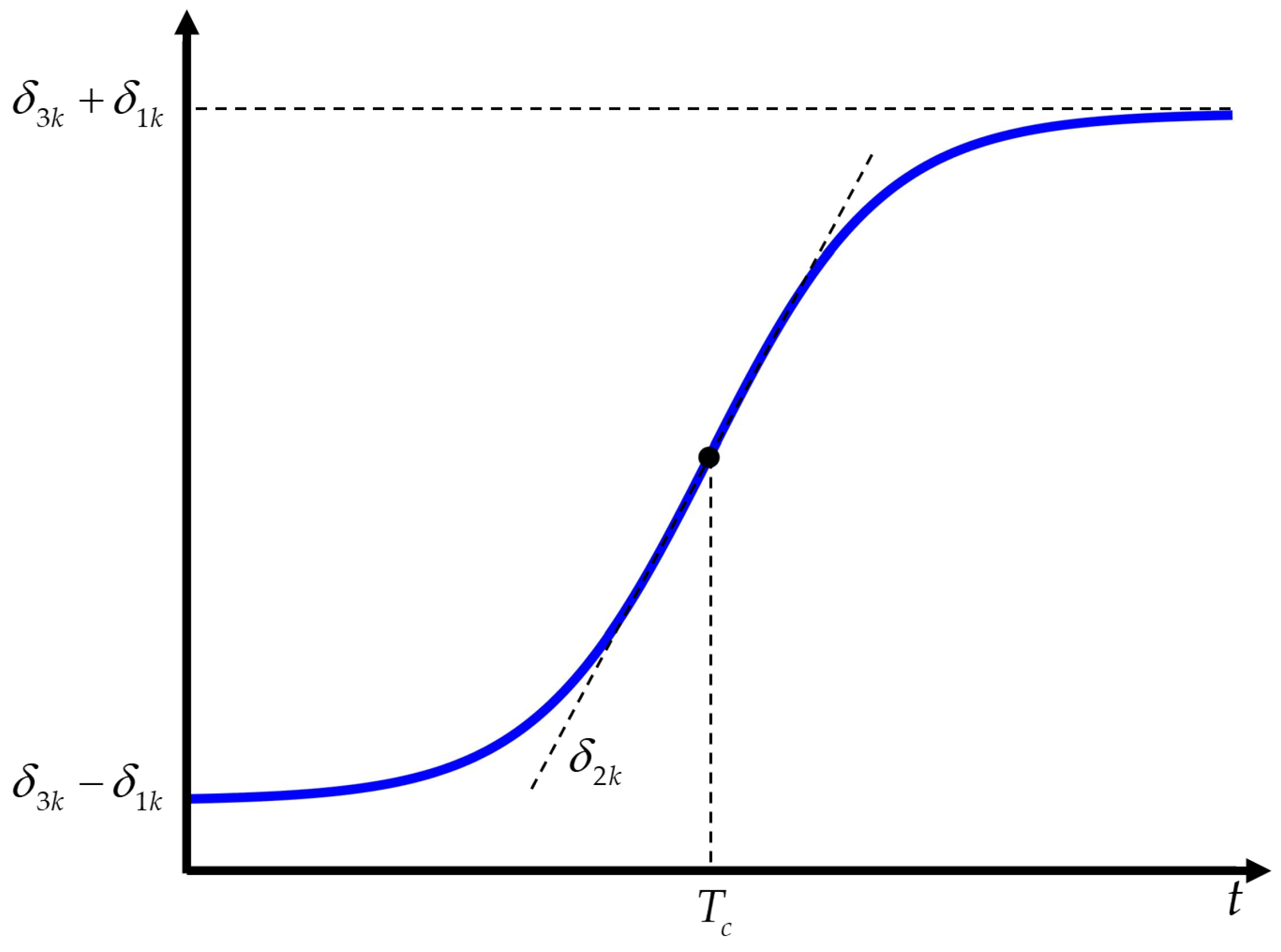
σ k = δ 1 k tanh δ 2 k t T c + δ 3 k , k = 1 , 2
where δ 1 k , δ 2 k and δ 3 k are positive constants; T c is a time constant; σ k > 0 .
The time-varying function described by (12) is illustrated in Figure 2. As shown in the figure, this smooth time-varying function, constructed around a tanh core, is bounded. Its bounds can be adjusted and precisely determined by the constants δ 1 k and δ 3 k . By modifying the time constant T c , the point at which the function begins to transition can be controlled. Furthermore, the rate of change from its minimum to maximum value can be regulated by adjusting the constant δ 2 k .
Motivated by the AESO design in [18,20], the time-varying gain l 1 j can be further designed in the following form
l 11 t = 2 ω 1 t l 12 t = 2 ω 1 2 t l 13 t = ω 1 3 t
in which ω 1 t = ϖ 01 σ 1 ; ϖ 01 > 0 can be interpreted as the bandwidth of the third-order AESO.
Notably, although the AESO in (11) achieves simultaneous estimation of system state x 2 and disturbance x e 1 , it fails to address unknown disturbance x e 2 . By utilizing the measurable system state x 3 , a second-order AESO can be designed for x e 2 estimation
x ^ ˙ 3 = f 2 x 3 , u u + f 3 x ^ 2 + l 21 t x 3 x ^ 3 x ^ ˙ e 2 = l 22 t x 3 x ^ 3
in which x ^ 3 , and x ^ e 2 represent the estimates of x 3 , and x e 2 , respectively; l 21 and l 22 denote the time-varying gain, with its expression can be defined as
l 21 t = 2 ω 2 t l 22 t = ω 2 2 t
where ω 2 t = ϖ 02 σ 2 ; ϖ 02 > 0 can be interpreted as the bandwidth of the second-order AESO.
To characterize the estimation error dynamics generated by the cascaded AESO, define the estimation error state variables as ε = ε 1 ; ε 2 ; ε 3 = x ˜ 1 ; x ˜ 2 / ω 1 t ; x ˜ e 1 / ω 1 2 t and η = η 1 ; η 2 = x ˜ 3 ; x ˜ e 2 / ω 2 t , in which x ˜ j = x j x ^ j ( j = 1 , 2 , 3 ), x ˜ e k = x e k x ^ e k ( k = 1 , 2 ). Combining (8), (11), and (14), the estimation error dynamics of the cascaded AESO are formulated as
ε ˙ = ω 1 t D 1 ε + E 1 h 1 t ω 1 2 t
η ˙ = ω 2 t D 2 η + E 2 f 3 x ˜ 2 + E 3 h 2 t ω 2 t
in which
D 1 = 2 1 0 2 0 1 1 0 0 , E 1 = 0 0 1 , D 2 = 2 1 1 0 , E 2 = 1 0 , E 3 = 0 1
Note that both D 1 and D 2 are Hurwitz; hence, positive definite matrices G 1 and G 2 exist satisfying
D 1 T G 1 + G 1 D 1 = 2 I 1 D 2 T G 2 + G 2 D 2 = 2 I 2
where I 1 3 × 3 and I 2 2 × 2 are identity matrices.
Based on the descriptions in (12) and Figure 2, combined with the definitions in (13) and (15), it can be further known that the time-varying gains of the AESO are bounded, and there exists a known positive constants ζ i ( i = 1 , 2 , 3 , 4 ) such that the following inequality holds:
ζ 1 ω 01 δ 31 δ 11 ω 1 t ω 01 δ 31 + δ 11 ζ 2 ζ 3 ω 02 δ 32 δ 12 ω 2 t ω 02 δ 32 + δ 12 ζ 4
Remark 2. 
The second-order AESO incorporates a state  x ^ 2  obtained from a preceding third-order AESO, establishing a cascaded observer structure with interdependent estimation performance. The finite-time convergence of a single AESO has been established in [18]. To demonstrate the stability of the cascaded AESO, the proof methodology from [20,21,22] is adopted, in which the observer errors, their coupled interactions, and the tracking errors of the closed-loop system are analyzed within a unified framework.

3.3. Controller Design

Inspired by [30], the following first-order filter is preliminarily introduced to simplify controller design and avoid ‘‘differential explosion”.
ν ˙ = τ ϑ ϑ = ν ο
with ο denotes the input of the command filter; ν is the filtered value of ο ; ν ˙ denotes the derivative of ν ; ϑ is the intermediate variable of the command filter; τ > 0 denotes the filter gain coefficient.
To preclude error accumulation due to filter cascading, filtering error compensation terms ξ j ( j = 1 , 2 , 3 ) are incorporated into subsequent controller design to counteract filter-induced effects.
Step 1: Define the set of error variables as
z j = e j ξ j , j = 1 , 2 , 3
in which
e 1 = x 1 x 1 d , e 2 = x ^ 2 α 1 f , e 3 = x 3 α 2 f α ˙ 1 f = τ 1 ϑ 1 , ϑ 1 = α 1 f α 1 , α ˙ 1 f 0 = 0 α ˙ 2 f = τ 2 ϑ 2 , ϑ 2 = α 2 f α 2 , α ˙ 2 f 0 = 0
where e j denote the errors in each component of the closed-loop system; α k f denote the filtered value of α k ; α k denote the virtual control laws of the controller, and their specific structures will be presented in subsequent parts of the paper; τ k are positive constants; ϑ k represent intermediate variables of the command filter; j = 1 , 2 , 3 , k = 1 , 2 .
The filtering error compensation term ξ 1 is designed as
ξ ˙ 1 = k 1 ξ 1 + α 1 f α 1 + ξ 2 , ξ 1 0 = 0
where k 1 is a positive constant gain.
Differentiating z 1 yields
z ˙ 1 = e ˙ 1 ξ ˙ 1 = x 2 x ˙ 1 d + k 1 ξ 1 α 1 f + α 1 ξ 2 = z 2 x ˙ 1 d + k 1 ξ 1 α 1 + ω 1 t ε 2
The virtual control law α 1 can be designed as
α 1 = k 1 e 1 + x ˙ 1 d
Substituting (26) into (25), z ˙ 1 can be rewritten as
z ˙ 1 = z 2 k 1 z 1 + + ω 1 t ε 2
Step 2: The filtering error compensation term ξ 2 can be designed as follows
ξ ˙ 2 = k 2 ξ 2 + α 2 f α 2 ξ 1 + ξ 3 , ξ 2 0 = 0
where k 2 is a positive constant gain.
Combining (11), (22), and (23), differentiating z 2 yields
z ˙ 2 = e ˙ 2 ξ ˙ 2 = x ^ ˙ 2 α ˙ 2 f + k 2 ξ 2 α 2 f + α 2 + ξ 1 ξ 3 = z 3 + f 1 x ^ 2 + x ^ e 1 + 2 ω 1 2 t ε 1 α ˙ 2 f + k 2 ξ 2 + α 2 + ξ 1
Hence, the virtual control law α 2 can be designed as
α 2 = k 2 e 2 f 1 x ^ 2 x ^ e 1 + α ˙ 2 f e 1
Substituting (30) into (29), z ˙ 2 can be rewritten as
z ˙ 2 = z 3 k 2 z 2 z 1 + 2 ω 1 2 t ε 1
Step 3: The filtering error compensation term ξ 3 can be designed as follows
ξ ˙ 3 = k 3 ξ 3 ξ 2 , ξ 1 0 = 0
where k 3 is a positive constant gain.
Differentiating z 2 yields
z ˙ 3 = e ˙ 3 ξ ˙ 3 = x ˙ 3 α ˙ 2 f + k 3 ξ 3 + ξ 2 = f 2 x 3 , u u + f 3 x 2 + x e 2 α ˙ 2 f + k 3 ξ 3 + ξ 2
Hence, the control input u can be designed as
u a = f 3 x ^ 2 x ^ e 2 + α ˙ 2 f e 2 f 2 x 3 , u , u s = k 3 e 3 f 2 x 3 , u u = u a + u s
Substituting (34) into (33), z ˙ 3 can be rewritten as
z ˙ 3 = f 3 x ^ 2 x ^ e 2 + α ˙ 2 f e 2 k 3 e 3 + f 3 x 2 + x e 2   α ˙ 2 f + k 3 ξ 3 + ξ 2 = k 3 z 3 z 2 + θ 1 ω 1 t ε 2 + ω 2 t η 2
where θ 1 = 4 β e A 2 / m / V t is a constant related to the physical parameters of the system.
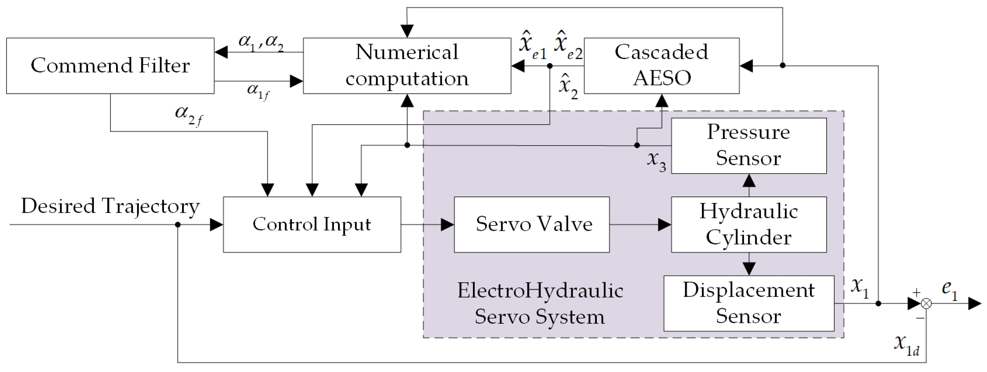
The controller design is thus completed, with Figure 3 depicting its operational logic.
Remark 3. 
The actual control program of the cascaded AESO can be implemented based on (11)–(15) and straightforward integral computation. Similarly, the core controller framework can be efficiently constructed using (26), (30), and (34), combined with the command filter given in (21). As these expressions involve only basic arithmetic operations without complex polynomial calculations, the controller is straightforward to program and suitable for practical applications. In contrast to the virtual control laws expressed in (21) and (25) of [21], the proposed controller incorporates a command filter to avoid differentiating complex virtual control terms, significantly reducing the computational complexity. Compared with [22], the proposed controller utilizes pressure sensors already available in hydraulic systems, eliminating the need for constructing high-order observers. Furthermore, owing to the simplicity of the command filter, the proposed controller shows potential for application in larger-scale systems.

3.4. Main Result and Stability Analysis

For rigorous subsequent analysis, the following scalar quantities are formally defined:
γ 1 = k 1 0.5 ζ 2 , γ 2 = k 2 ζ 2 2 , γ 3 = k 3 0.5 ζ 4 2 γ 4 = ζ 1 2 0.5 ζ 2 ζ 2 2 0.5 0.5 G 2 E 2 2 γ 5 = ζ 3 2 0.5 ζ 4 0.5 θ 1 2 ζ 2 2 0.5 γ 6 = k 1 0.5 , γ 7 = k 2 0.5
The main results of this paper are summarized as follows.
Theorem 1. 
Under the assumptions of this paper, with the control gains  k 1 , k 2 , k 3 and the observer bandwidth ϖ 01 , ϖ 02 selected to ensure positive definiteness of matrix Λ in (41), the following hold
(1)
The proposed controller guarantees bounded tracking error in the electrohydraulic servo system and bounded estimation error in the cascaded AESO.
(2)
The proposed controller ensures boundedness of all closed-loop signals.
Proof of Theorem 1. 
A positive-definite Lyapunov equation is constructed as follows
V = i = 1 3 z i 2 + 1 2 ε T G 1 ε + + 1 2 η T G 2 η + i = 1 3 ξ i 2
Differentiating V with respect to (16), (17), (19), (24), (27), (28), (31), (32), and (35) yields
V ˙ = z 1 z 2 k 1 z 1 + + ω 1 t ε 2 + z 2 z 3 k 2 z 2 z 1 + 2 ω 1 2 t ε 1 + z 3 k 3 z 3 z 2 + θ 1 ω 1 t ε 2 + ω 2 t η 2 + ξ 1 k 1 ξ 1 + α 1 f α 1 + ξ 2 + ξ 2 k 2 ξ 2 + α 2 f α 2 ξ 1 + ξ 3 + ξ 3 k 3 ξ 3 ξ 2 ω 1 t ε 2 + ε T G 1 E 1 h 1 t / ω 1 2 t ω 2 t η 2 + θ 1 ω 1 t η T G 2 E 2 ε 2 + η T G 2 E 3 h 2 t / ω 2 t
The following inequality is derived from Young’s inequality, Assumption 2, and (20)
ω 1 t z 1 ε 2 ζ 2 2 z 1 2 + ζ 2 2 ε 2 , 2 ω 1 2 t z 2 ε 1 ζ 2 2 z 2 2 + ζ 2 2 ε 2 ω 2 t z 3 η 2 ζ 4 2 z 3 2 + ζ 4 2 η 2 , ξ 1 α 1 f α 1 1 2 ξ 1 2 + 1 2 α 1 f α 1 2 ξ 2 α 2 f α 2 1 2 ξ 2 2 + 1 2 α 2 f α 2 2 , ε T G 1 E 1 h 1 t ω 1 2 t 1 2 ε 2 + G 1 E 1 2 μ 2 2 2 ζ 1 4 θ 1 ω 1 t η T G 2 E 2 ε 2 θ 1 2 ζ 2 2 2 η 2 + G 2 E 2 2 ε 2 2 , η T G 2 E 3 h 2 t ω 2 t 1 2 η 2 + G 2 E 3 2 μ 4 2 2 ζ 3 2
Substituting (20) and (39) into (38), it can be rewritten as follows
V ˙ γ 1 z 1 2 γ 2 z 1 2 γ 3 z 3 2 γ 4 ε 2   γ 5 η 2 γ 6 ξ 1 2 γ 7 ξ 2 2 k 3 ξ 3 2 + ς 1 χ T Λ χ + ς 1
in which χ = z 1 ; z 2 ; z 3 ; ε 1 ; ε 2 ; ε 3 ; η 1 ; η 2 ; ξ 1 ; ξ 2 ; ξ 3 and
Λ = d i a g γ 1 , γ 2 , γ 3 , γ 4 , γ 5 , γ 6 , γ 7 , k 3 ς 1 = 1 2 α 1 f α 1 2 + 1 2 α 2 f α 2 2 + G 1 E 1 2 μ 2 2 2 ζ 1 4 + G 2 E 3 2 μ 4 2 2 ζ 3 2
Since the matrix Λ is positive definite, it follows that
V ˙ λ min Λ i = 1 3 z i 2 + ε 2 + η 2 + i = 1 3 ξ i 2 + ς 1 λ min Λ i = 1 3 z i 2 + 1 λ max G 1 ε T G 1 ε + 1 λ max G 2 η T G 2 η + i = 1 3 ξ i 2 + ς 1 λ 1 V + ς 1
where λ 1 = 2 λ min Λ min 1 , 1 / λ max G 1 , 1 / λ max G 2 ; λ max and λ min represent the maximum and minimum eigenvalues of the matrix , respectively. □
Applying the comparison lemma [35], (42) admits the equivalent form
V t V 0 exp λ 1 t + ς 1 λ 1 1 exp λ 1 t
Based on (43), the following inequality can be derived:
χ 2 V 0 exp λ 1 t + 2 ς 1 λ 1 1 exp λ 1 t
From (44), it can be known that χ is bounded, which implies boundedness of z j , ε , η , and ξ j ( j = 1 , 2 , 3 ). Based on (22), errors e 1 , e 2 , and e 3 are bounded, thus proving the first conclusion of Theorem 1. Under Assumption 1, we can further know that system states x 1 , x 2 , and x 3 remain bounded. The boundedness of ε and η combined with Assumption 2 ensures bounded disturbance and state estimates. Finally, (34) and the preceding analysis establish bounded control input u , completing the proof of the second conclusion of Theorem 1. This completes the proof of Theorem 1. Furthermore, based on the definitions of χ and z 1 , the upper bound of the tracking error e 1 can be further described as
e 1 = z 1 ξ 1 z 1 + ξ 1 2 χ 2 2 V 0 exp λ 1 t + 2 ς 1 λ 1 1 exp λ 1 t
Remark 4. 
Unlike [36] and related studies, which construct the Lyapunov function around system states to prove stability, this paper builds the Lyapunov function based on the closed-loop errors and filtering error compensation terms. Both approaches can demonstrate the stability of the closed-loop system. However, as this paper focuses more on the dynamic tracking performance of the control system, the Lyapunov function construction follows a method similar to that in [6,9,10,22], which is more aligned with the goal of analyzing tracking accuracy and error convergence.

4. Simulation and Comparative Analysis

To validate the proposed controller, a Matlab/Simulink-based mathematical model of the electrohydraulic servo system in Figure 1 is established, with physical parameters listed in Table 1. To emulate system realism, inherent uncertainties and external disturbances are configured as: Δ 1 t = 200 sin 2 t and Δ 2 t = C t P L , in which C t denotes the internal leakage gain coefficient of the hydraulic cylinder.
In addition to the aforementioned data, the servo valve model adopted in this paper is the signal-conditioned MOOG G761, with a control input voltage range of ±10 V. Accordingly, the following constraint is imposed on the control input signal: 10 u 10 .
To demonstrate the superior performance of the proposed controller, two controllers are comparatively simulated, as detailed below.
(1)
CFVFTC-ADC (Command-filter-based velocity-free tracking controller with adaptive disturbance compensation): The proposed controller has its parameters set as follows: k 1 = 200 , k 2 = 500 , k 3 = 500 , ω 01 = 50 , ω 02 = 2 0 , τ 1 = τ 2 = 2000 and σ 1 = σ 2 = tanh 10 t 2 + 2 .
(2)
CFTC (Command-filter-based tracking controller): Compared with the proposed controller, this controller differs by numerically obtaining the system velocity state while lacking disturbance compensation capability. For fair comparison, controller parameter settings are maintained identically to those of CFVFTC-ADC.
(3)
CFVFTC-DC (Command-filter-based velocity-free tracking controller with disturbance compensation): In contrast to the proposed controller, this controller utilizes a conventional LESO for disturbance and state estimation. For a fair comparison, all controller parameters except the observer gains remain consistent with those of the CFVFTC-ADC. The LESO parameters are set as follows: ω 1 = 50 , ω 2 = 2 0 .
Remark 5. 
To facilitate efficient implementation of the proposed controller, a simplified procedure for tuning its gains is provided. First, after completing the initial programming, set all controller gains to small initial values. Subsequently, based on empirical knowledge, define the gain transition time point  T c  for the AESO. Then, adjust the constant gains δ 1 k , δ 2 k , δ 3 k , ω 01 and ω 02 of the AESO by comparing x 1 with x ^ 1 and x 3 with x ^ 3 , until x ˜ 1 and x ˜ 3 meet the system requirements, thereby completing the tuning of the cascaded AESO ( k = 1 , 2 ). Next, adjust the gain τ k of the command filter by comparing the virtual control laws α 1 and α 2 with their filtered values α 1 f and α 2 f ( k = 1 , 2 ). When ϑ 1 and ϑ 2 is sufficiently small and satisfies the performance criteria, the command filter tuning is considered complete. Finally, refine the robust gains k 1 , k 2 , and k 3 to reduce the tracking error e 1 . Note that minor adjustments to the previously mentioned gains may be necessary during this process. The tuning is concluded when further increasing k 1 , k 2 , and k 3 no longer reduces e 1 , and the control input u remains smooth and continuous. It should be noted that, when tuning the cascaded AESO, the third-order AESO should be adjusted prior to the second-order AESO to minimize the influence of x ^ 2 on the estimation performance of the latter.
To demonstrate performance, two distinct dynamic trajectories are employed for comparative evaluation; results are shown below.
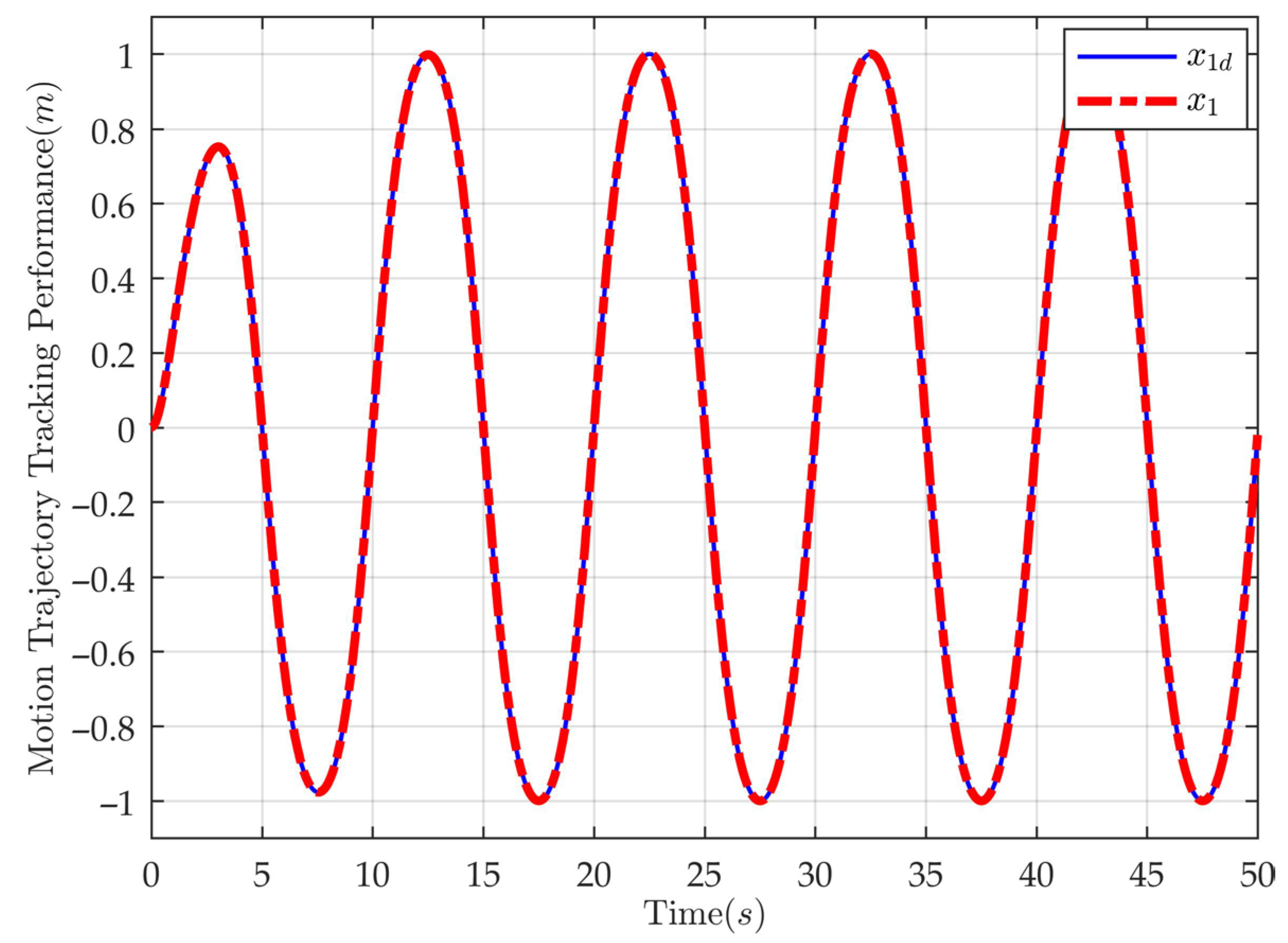
Case 1: To demonstrate the performance of the proposed controller under low-frequency, large-amplitude desired tracking conditions, a sinusoidal-like function is constructed, expressed as: x 1 d = arctan sin ( 0.2 π t ) 1 exp ( 0.5 t ) / 0.7854 . To simulate sensor measurement noise, a high-frequency, small-amplitude noise signal is superimposed on the displacement sensor readings based on the desired trajectory, expressed as: x n o s i e 1 = 1 × 10 6 arctan sin ( π t ) 1 exp ( 0.5 t ) / 0.7854 .
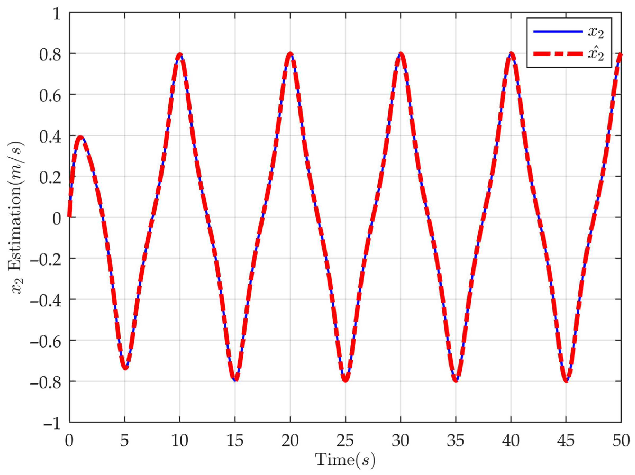
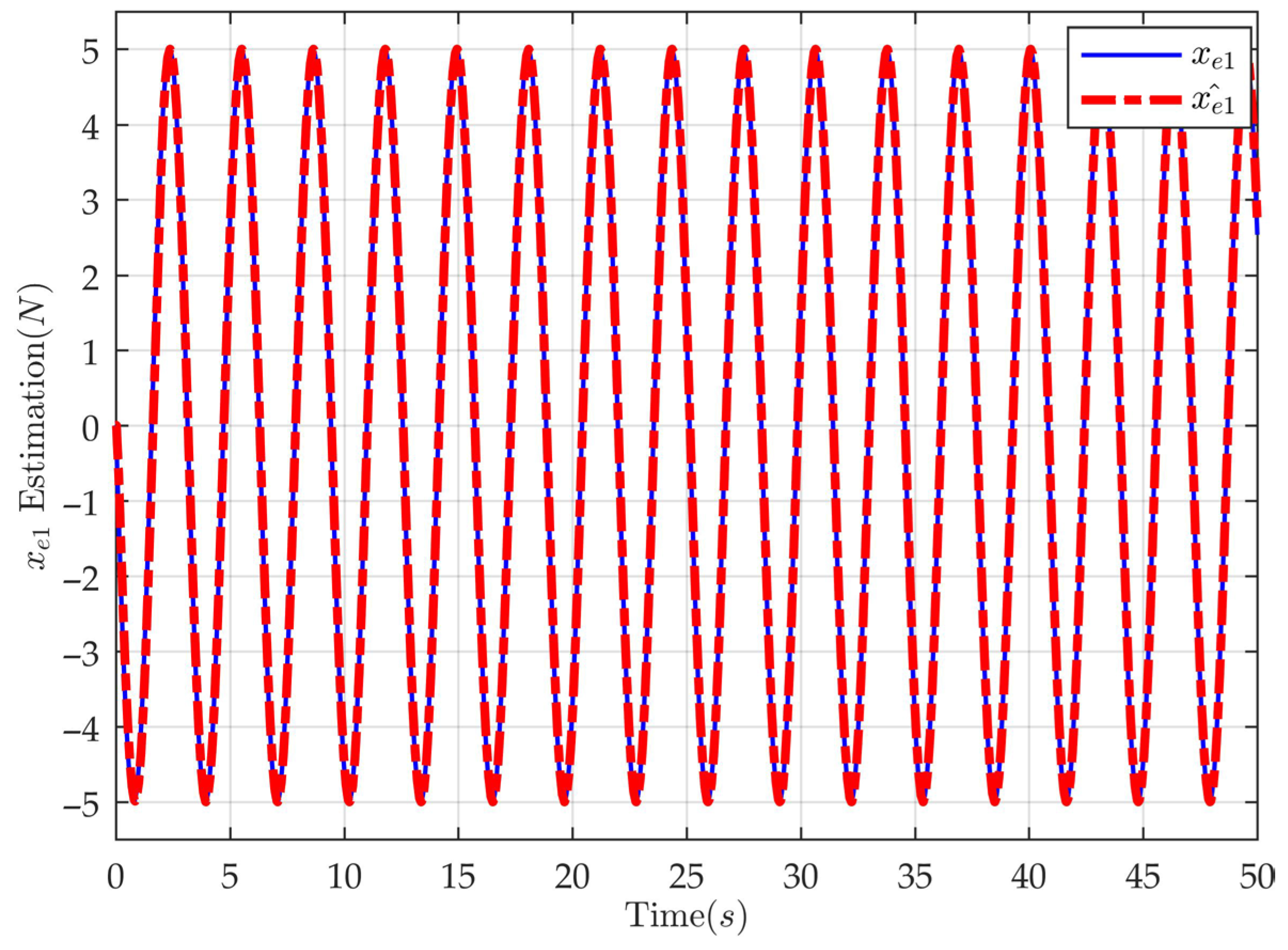
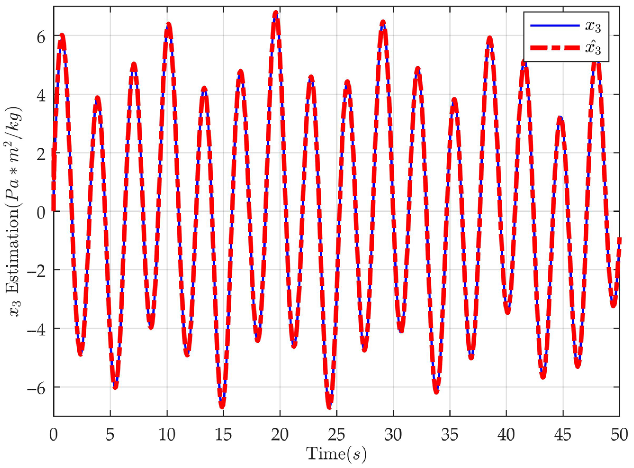
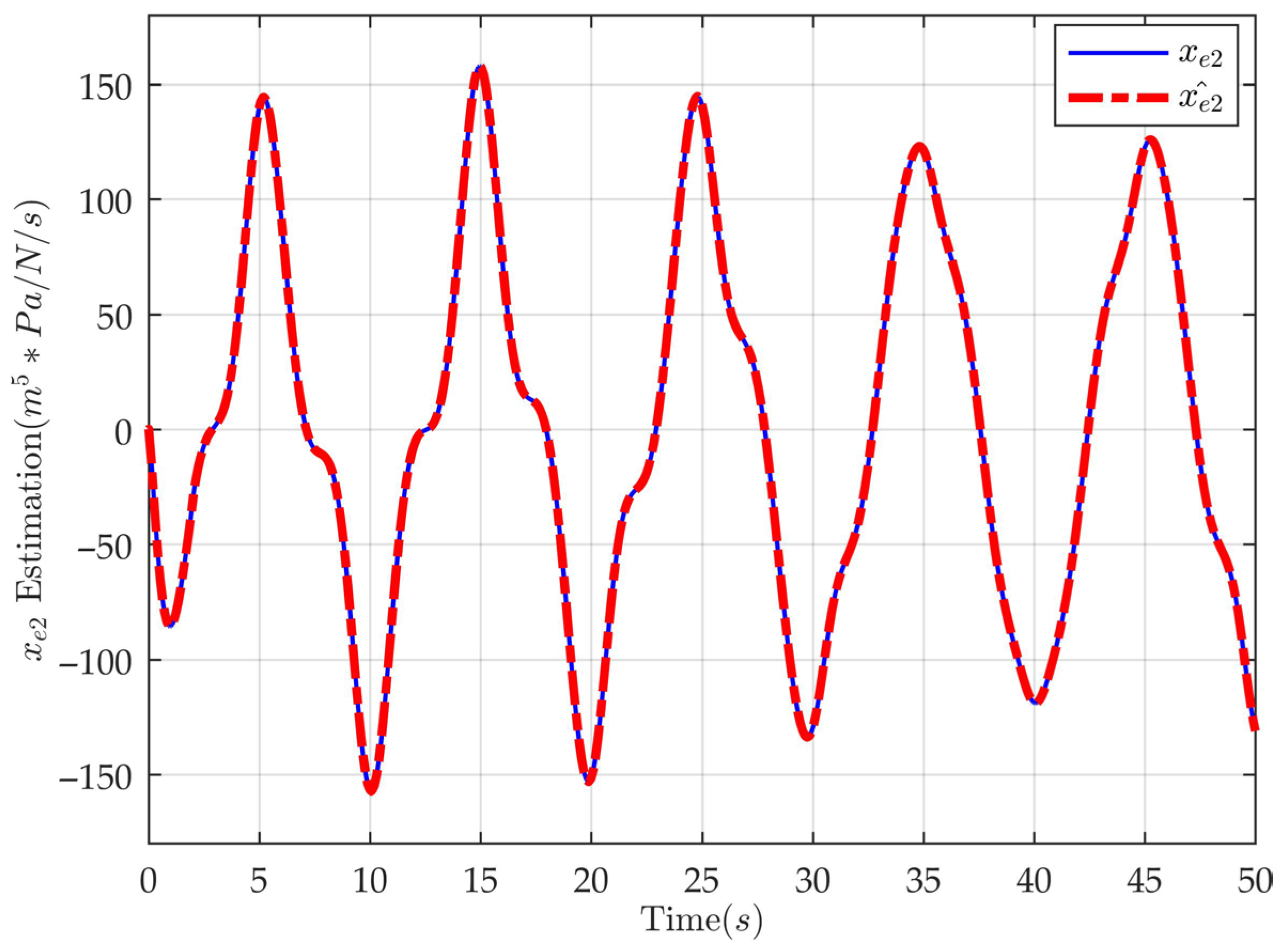
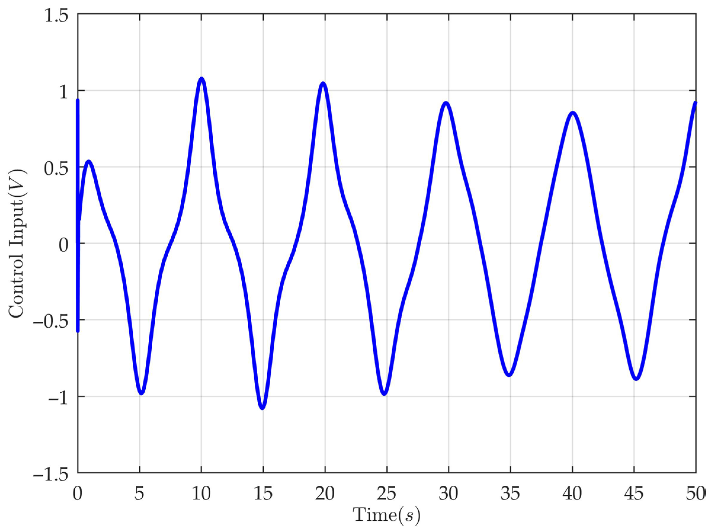
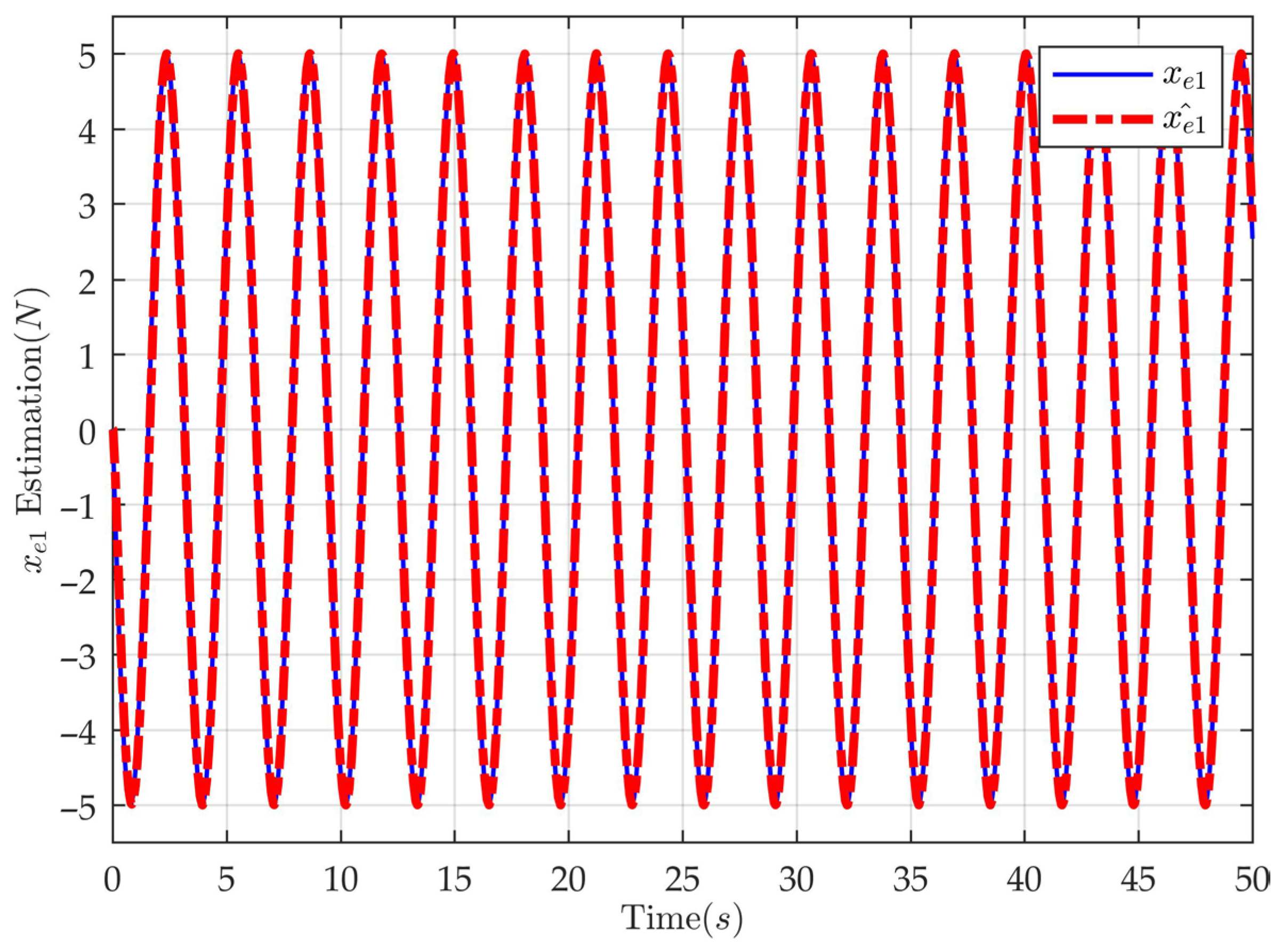
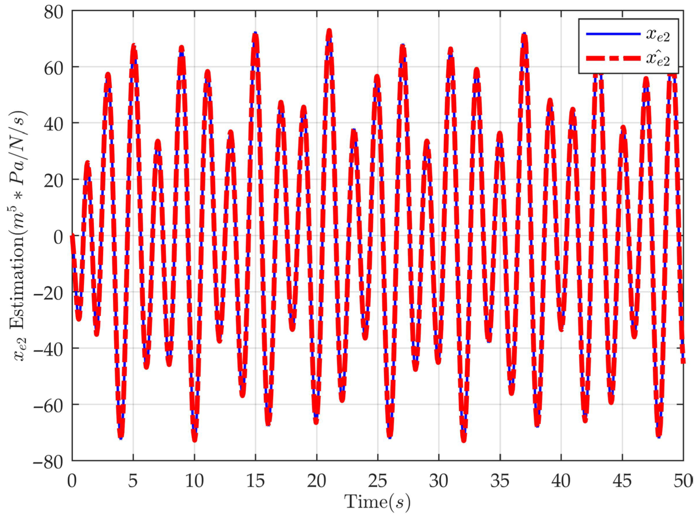
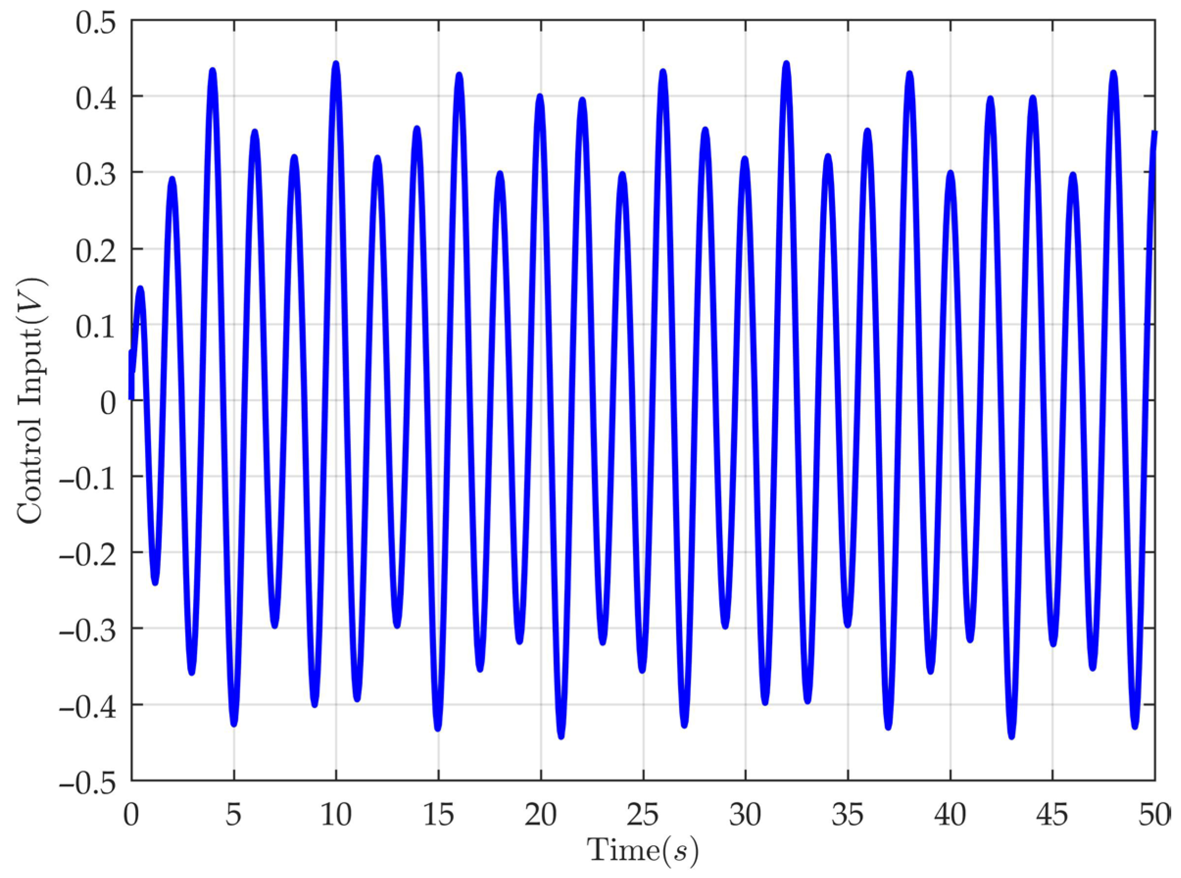
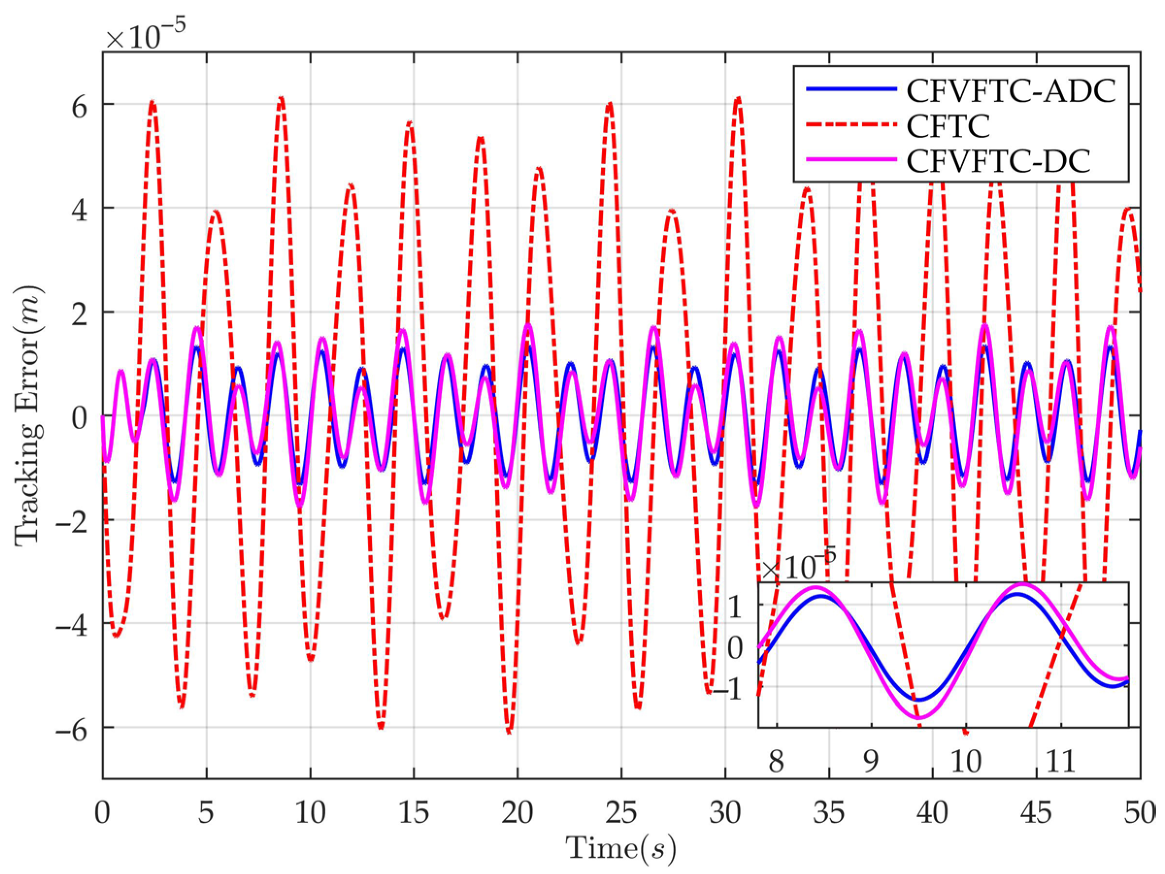
Figure 4 illustrates the alignment between the actual and desired system motion trajectory under CFVFTC-ADC. Figure 5, Figure 6, Figure 7, Figure 8 and Figure 9 present the estimation performance of the proposed cascaded AESO for system state and disturbances. Figure 5 and Figure 8 present estimations of known states, serving as accuracy benchmarks. Given the simulation-based validation, disturbances and unknown states can be derived from predefined functions and numerical methods. Figure 6 compares the estimated state x 2 with its theoretical true value, demonstrating the precision of the AESO. Similarly, Figure 7 and Figure 9 contrast estimated lumped disturbances x ^ e 1 and x ^ e 2 with their artificially set values. Results confirm the capability of the cascaded AESO to accurately estimate both unknown states and disturbances. Figure 10 presents the continuous and bounded control input generated by CFVFTC-ADC. Figure 11 presents the tracking error e 1 of the system under CFVFTC-ADC.
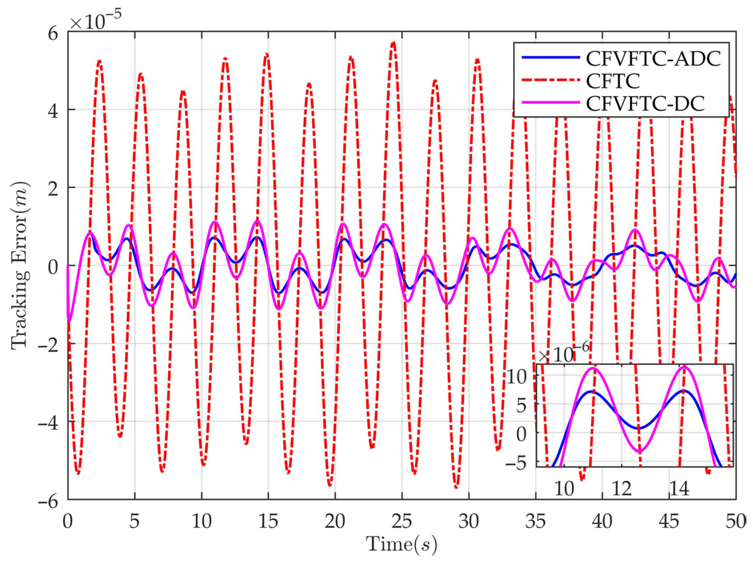
To evaluate the performance of the proposed controller, the mean M e a , median M e d , and root mean square R M S values are used as performance metrics (These metrics can be computed and viewed using the built-in Scope tool in Matlab/Simulink.). The corresponding results for the three controllers are summarized in Table 2. Furthermore, Figure 10 illustrates that the proposed controller generates smooth control signals. Figure 11 compares the dynamic control performance of the three controllers, using tracking error e 1 as the primary metric for evaluation. As shown in Figure 11 and Table 2, the proposed controller demonstrates superior performance. The results from Figure 4, Figure 5, Figure 6, Figure 7, Figure 8, Figure 9, Figure 10 and Figure 11 also corroborate the validity of Theorem 1.
Case 2: To demonstrate the performance of the proposed controller under high-frequency, small-amplitude desired tracking conditions, a sinusoidal-like function is constructed, expressed as: x 1 d = 0.1 sin ( π t ) 1 exp ( 2 t ) . Similar to Case 1, a measurement noise signal is introduced, expressed as: x n o i s e 2 = 1 × 10 7 sin ( 5 π t ) 1 exp ( 2 t ) .
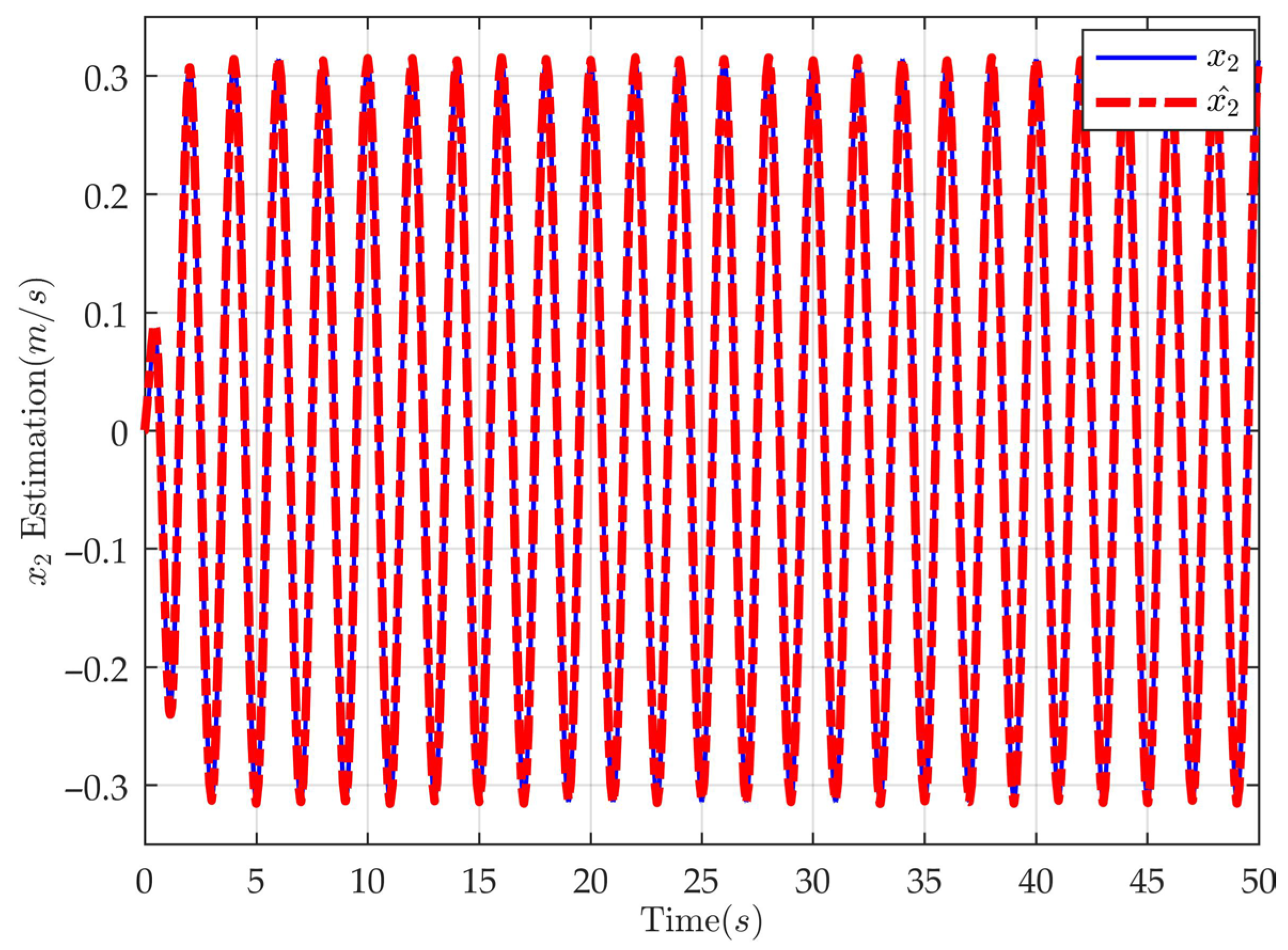
Similar to the previous analysis, key results of the CFVFTC-ADC and the control performance of the three controllers are presented in Figure 12, Figure 13, Figure 14 and Figure 15 to demonstrate the superiority of the proposed controller and validate Theorem 1. Figure 16 illustrates the smooth and continuous control signal generated by the controller. As shown in Figure 17 and Table 3, the proposed controller maintains superior performance even under high-frequency, small-amplitude desired trajectory tracking conditions. Figure 18 illustrates the time-varying gains of the AESO used in both Case 1 and Case 2, confirming that these gains remain bounded.

5. Conclusions

This paper proposes a command-filter-based velocity-free tracking controller for motion control of electrohydraulic servo systems, effectively achieving estimation of unknown system states and disturbance suppression. To obtain the system state x 2 and estimates of matched and mismatched disturbances, a cascaded AESO based on smooth gain functions is designed. To address the limitations of backstepping and avoid “differential explosion,” a first-order command filter is introduced, simplifying the controller design process. Lyapunov analysis demonstrates that the proposed controller ensures boundedness of all closed-loop signals, cascaded AESO estimation errors, and system tracking errors. Finally, simulations with two distinct desired trajectories confirm the superior performance of the controller. The differences between the proposed controller and existing controllers are summarized in Table 4.
However, the proposed controller still has room for improvement. For example, it currently relies on real-time signals from displacement and pressure sensors. Reducing this sensor dependency to achieve output feedback control represents a potential direction for enhancement. Furthermore, in practical applications, sensor data may be subject to packet loss or transmission interruptions due to issues such as cyber attacks [36]. The proposed controller currently lacks effective countermeasures against such scenarios, indicating significant potential for improvement. In addition to the aforementioned aspects, unlike the approaches in [37,38], the proposed controller does not provide a detailed treatment of parameter uncertainties, and its reliance solely on the AESO for lumped disturbance estimation remains a limitation. In future work, methods from [36,37,38] will be incorporated to enhance the proposed controller and address its current limitations. Moreover, while the effectiveness of the controller has been preliminarily validated on electrohydraulic servo systems, further validation on broader systems is necessary to demonstrate its general applicability.

Author Contributions

Formal analysis, G.Z., X.Y. and J.Y.; Investigation, C.L., G.Z. and W.D.; Methodology, G.Z., W.D. and X.Y.; Project administration, J.Y.; Writing—original draft, G.Z. and X.Y. All authors have read and agreed to the published version of the manuscript.

Funding

This work was supported in part by the National Key Research and Development Program of China under Grant 2024YFB4709600, the National Science and Technology Major Project of China under Grant 12124778012, the National Natural Science Foundation of China under Grant 52275062 and U24A20112, the Natural Science Foundation of Jiangsu Province under Grant BK20230096 and BK20232038, the Key R&D Program of Zhejiang under Grant 2024C04056(CSJ), the Special Project for Frontier Leading Technology Basic Research of Jiangsu Province under Grant BK20232031, the Fundamental Research Funds for the Central Universities under Grant 30925010301, the China Postdoctoral Science Foundation under Grant 2025M774266, and the Postdoctoral Fellowship Program of CPSF under Grant GZC20252675.

Data Availability Statement

The original contributions presented in the study are included in the article; further inquiries can be directed to the corresponding author.

Conflicts of Interest

Author Chuanjie Lu was employed by the company Dezhou Precion Machine Tool Co., Ltd. The remaining authors declare that the research was conducted in the absence of any commercial or financial relationships that could be construed as a potential conflict of interest.

References

  1. Patre, P.M.; MacKunis, W.; Dupree, K.; Dixon, W.E. Modular Adaptive Control of Uncertain Euler–Lagrange Systems with Additive Disturbances. IEEE Trans. Automat. Contr. 2011, 56, 155–160. [Google Scholar] [CrossRef]
  2. Yang, X.; Ge, Y.; Deng, W.; Yao, J. Precision Motion Control for Electro-Hydraulic Axis Systems under Unknown Time-Variant Parameters and Disturbances. Chin. J. Aeronaut. 2024, 37, 463–471. [Google Scholar] [CrossRef]
  3. Sun, W.; Pan, H.; Gao, H. Filter-Based Adaptive Vibration Control for Active Vehicle Suspensions with Electrohydraulic Actuators. IEEE Trans. Veh. Technol. 2016, 65, 4619–4626. [Google Scholar] [CrossRef]
  4. Won, D.; Kim, W.; Tomizuka, M. High-Gain-Observer-Based Integral Sliding Mode Control for Position Tracking of Electrohydraulic Servo Systems. IEEE/ASME Trans. Mechatron. 2017, 22, 2695–2704. [Google Scholar] [CrossRef]
  5. Pan, H.; Sun, W. Nonlinear Output Feedback Finite-Time Control for Vehicle Active Suspension Systems. IEEE Trans. Ind. Inf. 2019, 15, 2073–2082. [Google Scholar] [CrossRef]
  6. Ahn, K.K.; Nam, D.N.C.; Jin, M. Adaptive Backstepping Control of an Electrohydraulic Actuator. IEEE/ASME Trans. Mechatron. 2014, 19, 987–995. [Google Scholar] [CrossRef]
  7. Kaddissi, C.; Kenné, J.-P.; Saad, M. Indirect Adaptive Control of an Electrohydraulic Servo System Based on Nonlinear Backstepping. IEEE/ASME Trans. Mechatron. 2011, 16, 1171–1177. [Google Scholar] [CrossRef]
  8. Sun, W.; Gao, H.; Yao, B. Adaptive Robust Vibration Control of Full-Car Active Suspensions with Electrohydraulic Actuators. IEEE Trans. Contr. Syst. Technol. 2013, 21, 2417–2422. [Google Scholar] [CrossRef]
  9. Li, X.; Xia, H. A New Extended State Observer with Low Sensitivity to High Frequency Noise and Low Gain Power. IFAC-PapersOnLine 2020, 53, 4929–4934. [Google Scholar] [CrossRef]
  10. Yao, J.; Deng, W. Active Disturbance Rejection Adaptive Control of Hydraulic Servo Systems. IEEE Trans. Ind. Electron. 2017, 64, 8023–8032. [Google Scholar] [CrossRef]
  11. Chen, W.-H.; Yang, J.; Guo, L.; Li, S. Disturbance-Observer-Based Control and Related Methods—An Overview. IEEE Trans. Ind. Electron. 2016, 63, 1083–1095. [Google Scholar] [CrossRef]
  12. Hou, Q.; Ding, S.; Yu, X. Composite Super-Twisting Sliding Mode Control Design for PMSM Speed Regulation Problem Based on a Novel Disturbance Observer. IEEE Trans. Energy Convers. 2021, 36, 2591–2599. [Google Scholar] [CrossRef]
  13. Liu, Z.; Liu, J.; Zhang, O.; Zhao, Y.; Chen, W.; Gao, Y. Adaptive Disturbance Observer-Based Fixed-Time Tracking Control for Uncertain Robotic Systems. IEEE Trans. Ind. Electron. 2024, 71, 14823–14831. [Google Scholar] [CrossRef]
  14. Chen, J.; Shuai, Z.; Zhang, H.; Zhao, W. Path Following Control of Autonomous Four-Wheel-Independent-Drive Electric Vehicles via Second-Order Sliding Mode and Nonlinear Disturbance Observer Techniques. IEEE Trans. Ind. Electron. 2021, 68, 2460–2469. [Google Scholar] [CrossRef]
  15. Lakomy, K.; Madonski, R.; Dai, B.; Yang, J.; Kicki, P.; Ansari, M.; Li, S. Active Disturbance Rejection Control Design with Suppression of Sensor Noise Effects in Application to DC–DC Buck Power Converter. IEEE Trans. Ind. Electron. 2022, 69, 816–824. [Google Scholar] [CrossRef]
  16. Ma, Z.; Xiao, Y.; Wang, P.; Zhao, Y. Linear-Extended-State-Observer Based Pinning Control of Nonlinear Multi-Robots System. IEEE Access 2020, 8, 144522–144528. [Google Scholar] [CrossRef]
  17. Wang, C.; Quan, L.; Jiao, Z.; Zhang, S. Nonlinear Adaptive Control of Hydraulic System with Observing and Compensating Mismatching Uncertainties. IEEE Trans. Contr. Syst. Technol. 2018, 26, 927–938. [Google Scholar] [CrossRef]
  18. Pu, Z.; Yuan, R.; Yi, J.; Tan, X. A Class of Adaptive Extended State Observers for Nonlinear Disturbed Systems. IEEE Trans. Ind. Electron. 2015, 62, 5858–5869. [Google Scholar] [CrossRef]
  19. Zhao, L.; Cheng, H.; Xia, Y.; Liu, B. Angle Tracking Adaptive Backstepping Control for a Mechanism of Pneumatic Muscle Actuators via an AESO. IEEE Trans. Ind. Electron. 2019, 66, 4566–4576. [Google Scholar] [CrossRef]
  20. Lin, W.; Zhang, Z.; Yu, X.; Qiu, J.; Rudas, I.J.; Gao, H.; Qu, D. Adaptive Extended State Observer-Based Velocity-Free Servo Tracking Control with Friction Compensation. IEEE Trans. Syst. Man Cybern. Syst. 2024, 54, 2–11. [Google Scholar] [CrossRef]
  21. Yang, X.; Deng, W.; Yao, J. Neural Adaptive Dynamic Surface Asymptotic Tracking Control of Hydraulic Manipulators with Guaranteed Transient Performance. IEEE Trans. Neural Netw. Learn. Syst. 2023, 34, 7339–7349. [Google Scholar] [CrossRef]
  22. Yang, X.; Ge, Y.; Zhu, W.; Deng, W.; Zhao, X.; Yao, J. Adaptive Motion Control for Electro-Hydraulic Servo Systems with Appointed-Time Performance. IEEE/ASME Trans. Mechatron. 2025. early access. [Google Scholar] [CrossRef]
  23. Xia, J.; Zhang, J.; Feng, J.; Wang, Z.; Zhuang, G. Command Filter-Based Adaptive Fuzzy Control for Nonlinear Systems with Unknown Control Directions. IEEE Trans. Syst. Man Cybern, Syst. 2019, 51, 1945–1953. [Google Scholar] [CrossRef]
  24. Yu, J.; Zhao, L.; Yu, H.; Lin, C. Barrier Lyapunov Functions-Based Command Filtered Output Feedback Control for Full-State Constrained Nonlinear Systems. Automatica 2019, 105, 71–79. [Google Scholar] [CrossRef]
  25. Zheng, X.; Yu, X.; Jiang, J.; Yang, X. Practical Finite-Time Command Filtered Backstepping with Its Application to DC Motor Control Systems. IEEE Trans. Ind. Electron. 2024, 71, 2955–2964. [Google Scholar] [CrossRef]
  26. Li, M.; Li, S.; Ahn, C.K.; Xiang, Z. Adaptive Fuzzy Event-Triggered Command-Filtered Control for Nonlinear Time-Delay Systems. IEEE Trans. Fuzzy Syst. 2022, 30, 1025–1035. [Google Scholar] [CrossRef]
  27. Shen, Q.; Shi, P. Distributed Command Filtered Backstepping Consensus Tracking Control of Nonlinear Multiple-Agent Systems in Strict-Feedback Form. Automatica 2015, 53, 120–124. [Google Scholar] [CrossRef]
  28. Hao, R.; Wang, H.; Liu, S.; Yang, M.; Tian, Z. Multi-Objective Command Filtered Adaptive Control for Nonlinear Hydraulic Active Suspension Systems. Nonlinear Dyn. 2021, 105, 1559–1579. [Google Scholar] [CrossRef]
  29. Wan, Y.; Yue, W.; Gao, X.; Chen, Q.; Xu, R. Adaptive Finite-Time Prescribed Performance Tracking Control for Hydraulic Servo Systems with Friction Compensation. Neurocomputing 2024, 564, 126967. [Google Scholar] [CrossRef]
  30. Yang, X.; Deng, W.; Yao, J. Disturbance-Observer-Based Adaptive Command Filtered Control for Uncertain Nonlinear Systems. ISA Trans. 2022, 130, 490–499. [Google Scholar] [CrossRef]
  31. Xi, R.; Zhang, H.; Liang, Q.; Liu, X. Command Filtered Adaptive Tracking Control for a Class of Random Nonlinear Systems. IEEE Trans. Circuits Syst. II 2023, 70, 2087–2091. [Google Scholar] [CrossRef]
  32. Liu, J.; Wang, Q.-G.; Yu, J. Command-Filter-Approximator-Based Adaptive Control for Uncertain Nonlinear Systems and Its Application in PMSMs. IEEE Trans. Syst. Man Cybern. Syst. 2023, 53, 6828–6835. [Google Scholar] [CrossRef]
  33. Liu, W.; Zhao, H.; Shen, H.; Xu, S.; Park, J.H. Command-Filter-Based Predefined-Time Control for State-Constrained Nonlinear Systems Subject to Preassigned Performance Metrics. IEEE Trans. Automat. Contr. 2024, 69, 7801–7807. [Google Scholar] [CrossRef]
  34. Merritt, H. Hydraulic Control Systems; John Wiley & Sons: Hoboken, NJ, USA, 1967. [Google Scholar]
  35. Krstic, M.; Kanellakopoulos, I.; Kokotovic, P. Nonlinear and Adaptive Control Design; Wiley: New York, NY, USA, 1995. [Google Scholar]
  36. Doostmohammadian, M.; Meskin, N. Finite-Time Stability Under Denial of Service. IEEE Syst. J. 2021, 15, 1048–1055. [Google Scholar] [CrossRef]
  37. Fortuna, L.; Muscato, G. A Roll Stabilization System for a Monohull Ship: Modeling, Identification, and Adaptive Control. IEEE Trans. Contr. Syst. Technol. 1996, 4, 18–28. [Google Scholar] [CrossRef]
  38. Longo, D.; Muscato, G.; Nunnari, G. Neural network system identification for a low pressure non-linear dynamical subsystem onboard the alicia II climbing robot. IFAC Proc. Vol. 2003, 36, 369–374. [Google Scholar] [CrossRef]
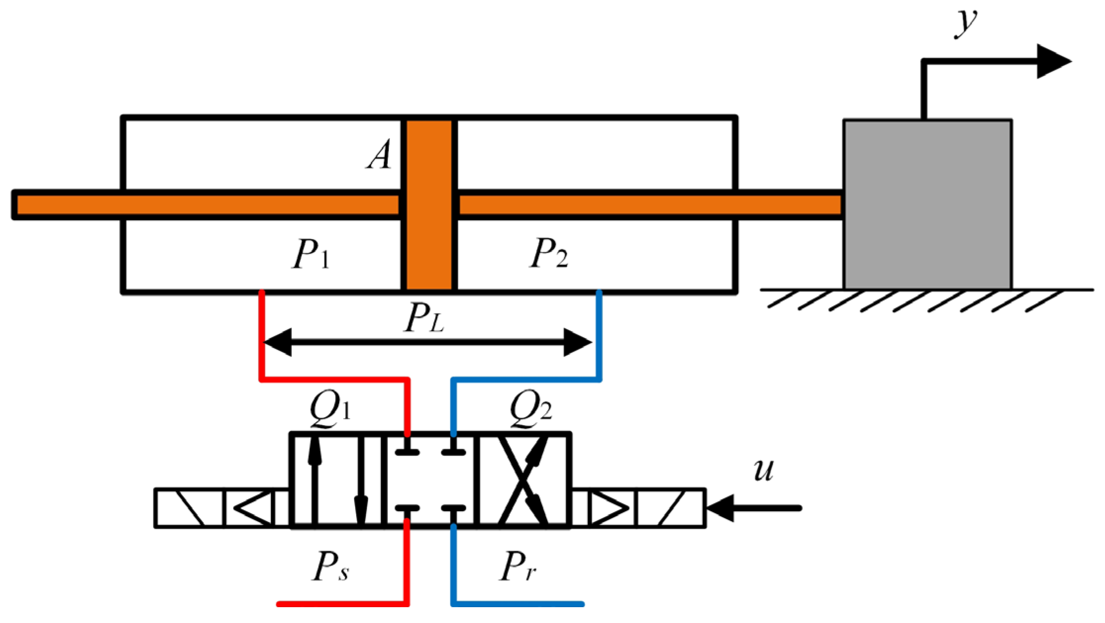
Figure 1. Schematic of the valve-controlled electrohydraulic servo system.
Mathematics 13 03081 g001
Figure 2. Schematic diagram of the smooth time-varying function σ k .
Mathematics 13 03081 g002
Figure 3. Operational logic diagram of the proposed controller.
Mathematics 13 03081 g003
Figure 4. The motion tracking performance of CFVFTC-ADC in case 1.
Mathematics 13 03081 g004
Figure 5. Third-order AESO estimation of x 1 in case 1.
Mathematics 13 03081 g005
Figure 6. Third-order AESO estimation of x 2 in case 1.
Mathematics 13 03081 g006
Figure 7. Third-order AESO estimation of x e 1 in case 1.
Mathematics 13 03081 g007
Figure 8. Second-order AESO estimation of x 3 in case 1.
Mathematics 13 03081 g008
Figure 9. Second-order AESO estimation of x e 2 in case 1.
Mathematics 13 03081 g009
Figure 10. Control input generated by CFVFTC-ADC in case 1.
Mathematics 13 03081 g010
Figure 11. Tracking error comparison under different controllers in case 1.
Mathematics 13 03081 g011
Figure 12. The motion tracking performance of CFVFTC-ADC in case 2.
Mathematics 13 03081 g012
Figure 13. Third-order AESO estimation of x 2 in case 2.
Mathematics 13 03081 g013
Figure 14. Third-order AESO estimation of x e 1 in case 2.
Mathematics 13 03081 g014
Figure 15. Second-order AESO estimation of x e 2 in case 2.
Mathematics 13 03081 g015
Figure 16. Control input generated by CFVFTC-ADC in case 2.
Mathematics 13 03081 g016
Figure 17. Tracking error comparison under different controllers in case 2.
Mathematics 13 03081 g017
Figure 18. Time-varying gains of the cascaded AESO.
Mathematics 13 03081 g018
Table 1. Mathematical model parameters of the electrohydraulic servo system.
ParameterValueParameterValue
m (kg)40Ps (MPa)7
Pr (MPa)0A (m2)2 × 10⁻⁴
B (N·s/m)80Vt (m3)2 × 10⁻³
β e (MPa)200kt ( m 4 / ( s V N ) )9.25 × 10⁻⁸
C t (m5/(N·s))7 × 10−12
Table 2. Controller performance metrics in case 1.
Metrics (m) M e a M e d R M S
CFVFTC-ADC−1.476 × 10⁻⁷−6.721 × 10−74.315 × 10−6
CFTC−2.507 × 10⁻⁷−4.551 × 10−73.626 × 10−5
CFVFTC-DC−1.502 × 10⁻⁷−2.765 × 10−95.943 × 10−6
Table 3. Controller performance metrics in case 2.
Metrics (m) M e a M e d R M S
CFVFTC-ADC−3.647 × 10⁻⁸−1.190 × 10−78.065 × 10−6
CFTC−1.410 × 10⁻⁷−4.963 × 10−73.655 × 10−5
CFVFTC-DC−3.686 × 10⁻⁸−1.047 × 10−79.223 × 10−6
Table 4. Differences between the proposed controller and existing controllers.
No.Detailed Description
1A novel cascaded AESO structure is developed, enabling simultaneous estimation of the system velocity state along with both matched and mismatched disturbances.
2A smooth time-varying function is constructed to formulate the AESO gains, replacing the conventional piecewise function approach.
Disclaimer/Publisher’s Note: The statements, opinions and data contained in all publications are solely those of the individual author(s) and contributor(s) and not of MDPI and/or the editor(s). MDPI and/or the editor(s) disclaim responsibility for any injury to people or property resulting from any ideas, methods, instructions or products referred to in the content.