1. Introduction
Pipe-jacking technology is widely used in urban underground pipeline construction because it causes little disturbance to the ground and can handle complex environments [
1]. However, during the pipe-jacking process, the actual position of the pipe-jacking may deviate from the planned trajectory due to uneven geological conditions, soil hardness, and thrust changes [
2,
3]. Therefore, in long-distance or curved projects, the pipe-jacking machine needs a guidance system with higher accuracy and real-time performance [
4,
5]. The fiber optic gyroscope-inertial navigation system (FOG-INS) has become a main solution for such tasks because it can work without external signals and has strong resistance to interference [
6,
7]. The navigation accuracy of the strap-down inertial navigation system (SINS) depends on the measurement accuracy of the inertial measurement unit (IMU) [
8]. IMU error correction is done by estimating the parameters of the error model in order to reduce the accumulated error of the system. To achieve high-accuracy navigation, the IMU must be corrected when used [
9]. The IMU usually includes three gyroscopes and three accelerometers. The outputs of the gyroscope and accelerometer contain bias errors, scale factor errors, installation errors, and random noise [
10]. Current methods for correcting errors in inertial navigation systems can be divided into two main categories. One method treats the system as a group of separate sensors and builds an error model to estimate parameters for each part. These methods often use data collected under static or nearly static conditions. This method estimates bias, scale factor, and other errors by analyzing the sensor output. The other method makes the system as a whole. It focuses on how different error sources interact with each other. It uses planned motion paths to excite the errors. Then, filtering algorithms are used to estimate and correct the system errors in real time during movement [
11]. The second method has a better ability to identify system errors. It does not need high-precision tools to work. This improves the usefulness of the system in real engineering projects, especially in pipe-jacking and other cases that require continuous online error correction.
Currently, many studies have focused on improving the correction of system errors in inertial navigation systems. These improvements mainly include path design, error modeling, and iterative algorithms. Most of these methods can work with low-cost turntables. Wei et al. proposed a 30-dimensional Kalman filter to estimate constant bias, scale factor error, and installation error of the gyroscope and accelerometer. The correction method significantly improved navigation accuracy [
12]. Wang et al. proposed a correction method using clockwise and counterclockwise multi-cycle rotations. This method was used to estimate accelerometer and gyro bias [
13]. Camberlein et al. designed a path with 18 attitude positions to improve correction accuracy. Using this method, a laser gyro system could reach navigation-grade accuracy within 20 min [
14]. Bai et al. proposed an optimal path planning method based on an improved Dijkstra algorithm. Simulation results showed that the correction accuracy reached 90% within 330 s [
15]. Xu et al. developed a coarse-to-fine correction method for FOG-based IMUs. The method used a low-cost rotary table and Kalman filtering, which effectively improved the overall system accuracy [
16]. Xie et al. designed a correction scheme that supports continuous rotation. The method considered test equipment, test duration, and test conditions during the correction process [
17]. Geng et al. used multi-position rotation to excite system errors and applied a 33-dimensional Kalman filter for parameter estimation. The simulation was conducted under static and low-angle motion conditions to verify the method’s effectiveness [
18]. Some researchers also included higher-order errors in the model and proposed nonlinear models. These models are more detailed, but often involve high computational complexity and large processing load. In practical use, adding too many minor factors may not improve accuracy or efficiency, making such methods less suitable for engineering applications [
19]. In summary, correction methods based on Kalman filtering can be applied to IMUs with different accuracy levels. These methods usually require only low-cost turntables, or in some cases, no external devices at all.
In pipe-jacking construction, the FOG-INS is installed at the head of the machine. This setup makes it difficult to apply multi-degree-of-freedom attitude excitation. Traditional correction methods for system errors often rely on multi-attitude sequences or complex motion paths, which are hard to use in pipe-jacking environments. Static multi-position methods are easier to implement, but they suffer from slow error convergence and long correction times, which may delay construction progress. Therefore, a suitable correction scheme is needed based on the actual working conditions of pipe-jacking to improve the measurement accuracy of the inertial guidance system.
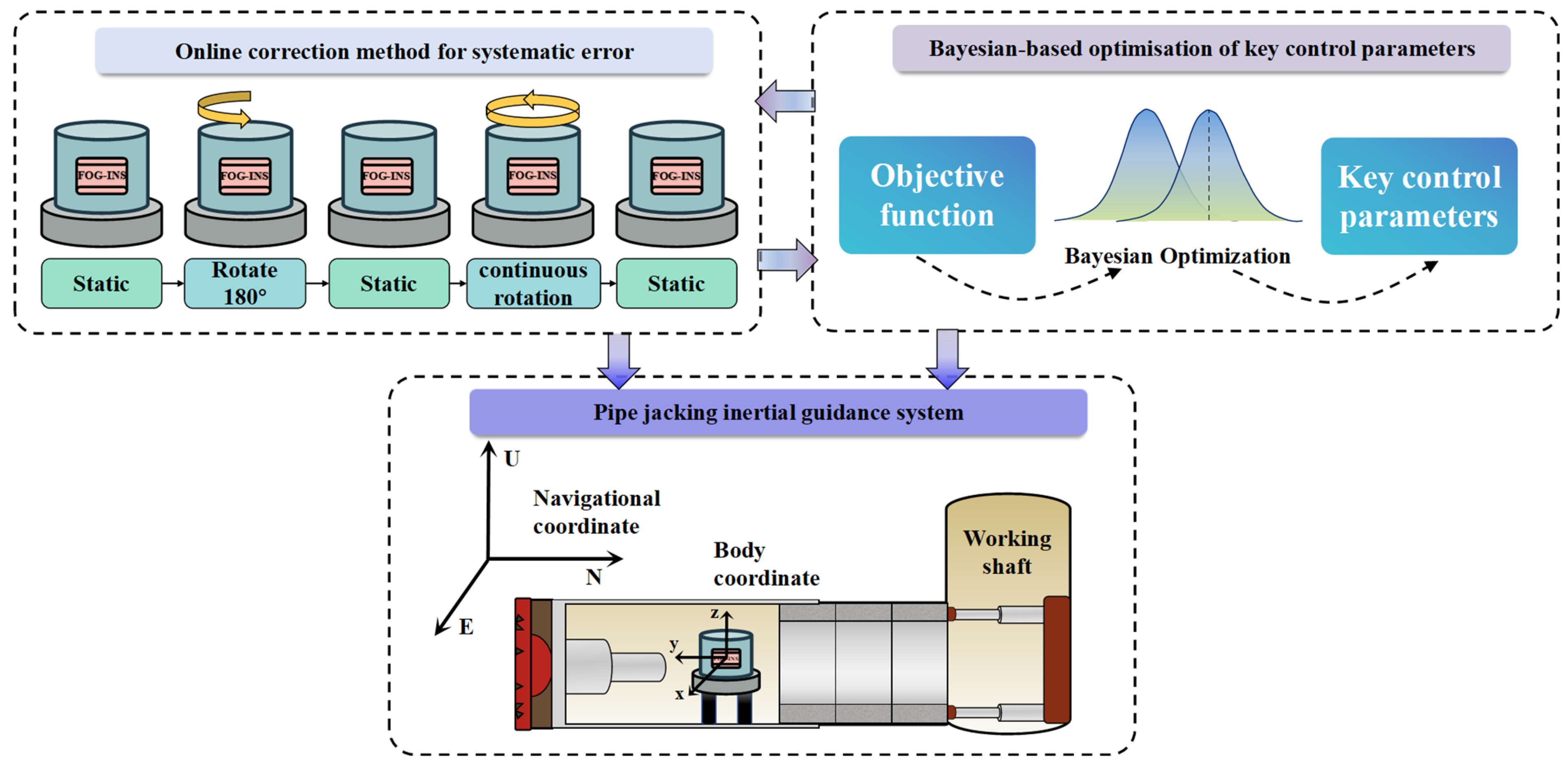
This study proposes an intelligent online correction method for system errors in a pipe-jacking inertial guidance system, combining single-axis rotation and data backtracking, as shown in
Figure 1. A low-cost single-axis turntable is used to excite system errors. Then, a Kalman filter model is built to estimate and compensate for these errors. Meanwhile, data backtracking is used to speed up filter convergence. A Bayesian optimization (BO) algorithm is applied to automatically determine the optimal alignment time and number of rotations at each phase. The method enables accurate online observation and dynamic compensation of key error sources.
2. Methodology
2.1. System Error Sources
In the inertial navigation system, common system errors include zero bias error of gyroscope and accelerometer, proportional factor error, installation angle error, and non-orthogonal error, etc. The error model of the gyroscope and accelerometer is as follows.
- a.
Gyroscope error models
where
are the ideal values of
x,
y and
z axis gyroscopes respectively;
are the zero bias of the gyro
x,
y and
z axes respectively in the carrier coordinate system;
are the measured values of
x,
y and
z axis gyroscopes respectively;
are the scale factors of
x,
y and
z axes of the gyroscope respectively;
,
,
are the errors of scale factor in
x,
y and
z axes of gyroscope respectively;
are the yaw angle of gyroscope
j axis to
i axis.
- b.
Accelerometer error model
where
are the ideal values of
x,
y and
z axes of accelerometer respectively;
,
,
are the zero bias of
x,
y and
z axes of accelerometer in body coordinate system;
,
,
are the
x,
y and
z axis measurements of the accelerometer;
,
,
are the acceleration scale factors of
x,
y and
z axes respectively;
,
,
are the errors of acceleration scale factors
x,
y and
z axes;
are the misalignment of accelerometer
j axis to
i axis.
The bias error continuously accumulates over time in the form of integration and is the main cause of navigation drift. In contrast, scale factor error and installation error also affect system accuracy, but their influence is limited in pipe-jacking applications where attitude excitation is restricted and ambient temperature remains stable. These errors change slowly and can be treated as second-order small quantities, with limited contribution to long-term error accumulation.
For yaw, the first-order linearized error is as follows.
During normal propulsion, both and the integrated rotations are small. Consequently, the scale-factor term and the installation terms remain limited, whereas the bias term accumulates linearly with time and dominates long-term drift. Using typical values , . When T = 10,000 s, , ; for a 180° two-position rotation, , and for ten turns (3600°) during calibration, . By comparison, a bias stability of , drift over 10,000 s. Therefore, under pipe-jacking conditions, it is reasonable to treat scale-factor and installation errors as second-order while modeling gyro/accelerometer biases online, achieving a practical balance between estimation accuracy and computational complexity.
Therefore, this study focuses on the bias errors of the gyroscope and accelerometer in system error modeling and observability analysis. This approach ensures modeling accuracy while reducing the state dimension and computational complexity.
2.2. System Error Model
If the inertial navigation system is rotated to a different angular position during the correction process, the attitude matrix of the system will change. This converts the constant system in the inertial error model into a time-varying system. As a result, system observability can be improved, which helps increase the accuracy of attitude angle estimation.
Among Equation (3).
where
is the rate of change in the state with time. Where
F is the Jacobian matrix of the system dynamics, which serves as the state transition matrix in the extended Kalman filter framework,
G is the noise input matrix, and
W is the process noise. The state quantity
X selects the attitude errors in the east, north, and up directions (
); the position errors contained the latitude, longitude, and height errors (
); the velocity errors contained the east, north and up errors (
); the gyroscope and accelerometer zero bias along the three axes (
).
is the identity matrix,
is the attitude matrix of INS,
indicates gyroscope noise,
indicates accelerometer noise,
indicates velocity observation noise, and
is the position observation noise.
2.3. System Error Observability Analysis
In Kalman filtering, the convergence of observable state variables indicates good performance in error estimation. Therefore, this study analyzes system observability using the covariance estimation method within the Kalman filter framework. The covariance matrix Pk reflects the covariance relationships between different state variables. The diagonal elements represent the estimation error of each state component. The variation range of these elements provides a quantitative measure of the estimation performance.
The observability of the state components
(
) are defined as follows.
where
is the variance of the
j state component at the initial moment,
is the variance of the
k state component at the initial moment.
As defined, observability is the ratio of standard deviations between state components at time 0 and time k, which is a dimensionless quantity. Therefore, a larger value indicates that the corresponding state component error decreases more significantly after filtering, and the improvement in precision becomes more pronounced. Based on the experience, the criteria for judging the strength of observability are generally as follows.
Under static conditions, the navigation output velocity is the velocity error. According to the error propagation rule of the INS, the misalignment heading angle error can be inferred from the velocity error. When
and
. The error equations can be obtained as follows.
In Equation (11), the equation is decoupled from the others. Therefore, under static conditions, the influence of vertical velocity and accelerometer bias is usually ignored. To estimate all bias errors, position variation or rotational excitation is required. In pipe jacking, the accuracy of roll angle measurement is not critical. Considering environmental and operational limitations, this study adopts a single-axis rotation method, with the Z-axis as the rotation axis.
2.4. Data Backtracking Technology
To further improve the convergence speed of the Kalman filter, this study introduces a data backtracking technology. During the estimation process, a segment of historical data, including observations, state transition matrices, and covariance matrices, is cached in real time. The filter then reuses the data to repeat the prediction and update steps. This approach provides stronger error excitation and leads to more accurate estimation results [
20].
In the inertial navigation system, the estimation of system errors relies on the residuals between navigation results and external measurements, as well as continuous motion excitation. Traditional Kalman filters update system states in a forward time sequence, which often requires multiple sampling periods to achieve accurate estimation. By introducing data backtracking, static data can be reused multiple times to accelerate error convergence and enable faster estimation.
Based on the standard forward navigation algorithm, this study derives its reverse form. Let k be the current time of data backtracking, and N is the window length. Use the geographic coordinate system as the navigation coordinate system. The forward navigation process is as follows.
Equation (13) is the attitude update engineering, Equation (14) is the velocity update process, and Equations (15)–(17) are the position update process.
In Equation (13) , .
In Equation (14) .
where the superscript n is the east, north, and up coordinate system, the superscript b is the body coordinate system, and the subscript k is the forward time series, with k increasing from 1 to N. The Ts is the sampling interval. and represent the measurement of gyroscope angular velocity and the measurement of accelerometer ratio force, respectively. and represent the local Earth rate and gravity vector. (•×) is the antisymmetric matrix formed by vectors •.
In Equation (18) .
2.5. Correction Method for System Errors
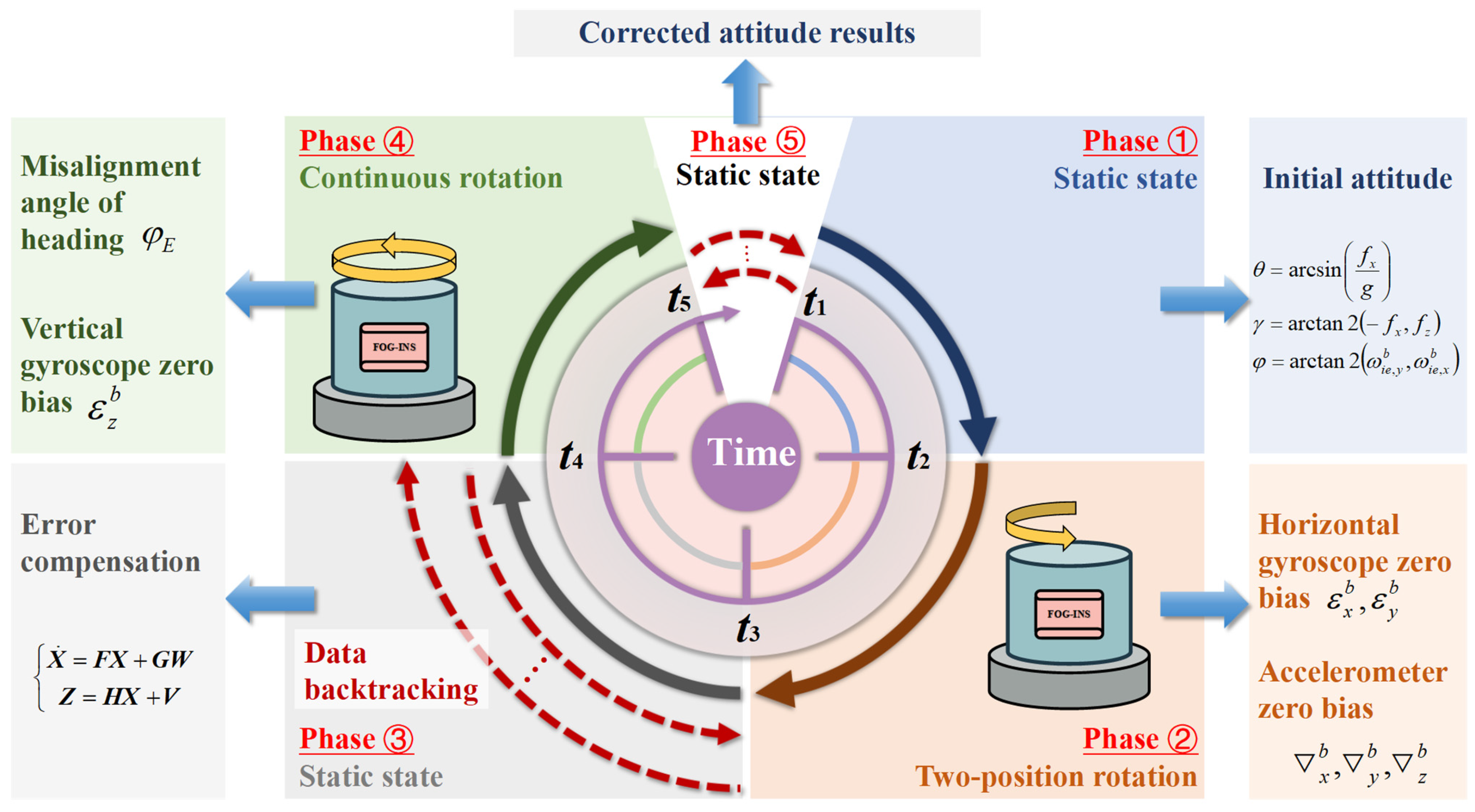
According to the navigation error propagation model, the vertical gyro bias is weakly observable, the east gyro bias and heading angle are jointly observable, and the horizontal accelerometer bias and horizontal attitude are also jointly observable. This method uses single-axis rotation to excite the dynamic response of the system, which helps separate different errors and improve estimation accuracy. Therefore, this study designs a fast online correction method for system errors, considering the installation and working conditions of the FOG-INS on a pipe jacking machine, as shown in
Figure 2.
As shown in
Figure 2, the entire correction process is divided into the following stages.
Phase 1 (t1–t2): Static state. After the system starts, initial static data is used to obtain a coarse alignment between the inertial navigation system and the geographic coordinate system, providing a rough estimate of attitude.
Phase 2 (t2–t3): Two-position rotation. The system conducts a 180° clockwise rotation to excite the horizontal accelerometer bias and horizontal gyro bias. Combined with changes in the state transition matrix, the observability of the system states is improved, allowing for effective error estimation and compensation.
Phase 3 (t3–t4): Static state. After initial error excitation and identification, the system enters a static state phase. The proposed Kalman filter model is applied to compensate for the estimated errors and improve attitude accuracy. At the same time, data backtracking is introduced to reuse historical data during this phase, accelerating convergence and reducing static waiting time.
Phase 4 (t4–t5): Continuous rotation. The system conducts continuous rotation around the Z-axis to enhance observability of the heading error and vertical gyro bias. This helps further excite and estimate weakly observable error sources.
Phase 5 (t5–): Static state. Another round of static state with data backtracking is conducted to compensate for newly excited error components.
2.6. Optimization of Key Control Parameters Based on Bayesian Algorithm
The performance of the proposed online system error correction method depends not only on error modeling and filter design but also on several key control parameters. Improper parameter selection may lead to poor error observability, slow filter convergence, or even divergence. Therefore, it is necessary to introduce an efficient, global, and gradient-free optimization strategy for parameter tuning. In this study, a BO based method is proposed to find the best parameters, which aim to improve error estimation accuracy and speed up convergence.
The basic idea of BO is to build a surrogate model of the objective function using previously sampled data. A Gaussian Process (GP) is typically used to model this surrogate function.
In the model,
represents the mean function, and
represents the covariance kernel function. This model can be used to predict the distribution of the objective function values under any parameter combination and quantify the uncertainty of the prediction. An acquisition function is then used to guide the search by selecting points with either high predicted values or high uncertainty, helping to find the optimal solution of the objective function.
According to the proposed online correction scheme for system errors, the variable parameters used in the BO process are listed in
Table 1.
To accurately determine the parameters for continuous rotation, this study builds a comprehensive objective function that includes multiple performance metrics. The specific optimization objectives are as follows.
- (1)
Zero bias root mean square error (RMSEbias). Reflects the accuracy of the filter in estimating the gyroscope bias. It is a key indicator of error compensation capability.
- (2)
Time variance of observation residuals (Varres). Measures the fluctuation of residuals between observations and predictions, indicating the stability of the filter during convergence.
- (3)
System observability (). Defined based on the variation of the covariance matrix, this index evaluates the identifiability of key state variables during the estimation process.
- (4)
Azimuth error (). The difference between the estimated azimuth after alignment and the reference value indicates the accuracy of final attitude estimation.
Considering the coupling among the above objectives, optimizing each metric independently may lead to degraded overall performance or deterioration in some aspects. Therefore, all performance indicators are normalized and integrated into a weighted multi-objective optimization function. The weighted evaluation ensures a balanced trade-off among bias estimation accuracy, filter convergence, system observability, and attitude precision.
The final structure of the optimization objective function is as follows.
In the formula,
are the weighting factors, which reflects the relative importance of each sub-objective to the overall system performance. To balance error estimation accuracy and attitude output precision, this study determines the weight factor through empirical priority. Before scalarization, all criteria are normalized by engineering targets so that they are dimensionless and comparable. We then elicit swing importance scores that reflect operational priorities in pipe-jacking guidance:
> RMSE
bias >
> Var
res. Assigning integer scores
to
and normalizing yields.
Variable parameters for BO are shown in
Table 2.
Based on the constructed weighted multi-objective optimization function, this study applies the BO algorithm to perform a global search for key parameters within a predefined search space.
In 30 repeated runs with a maximum of 100 iterations, the objective function consistently reached its minimum before iteration 50, as shown in
Table 3.
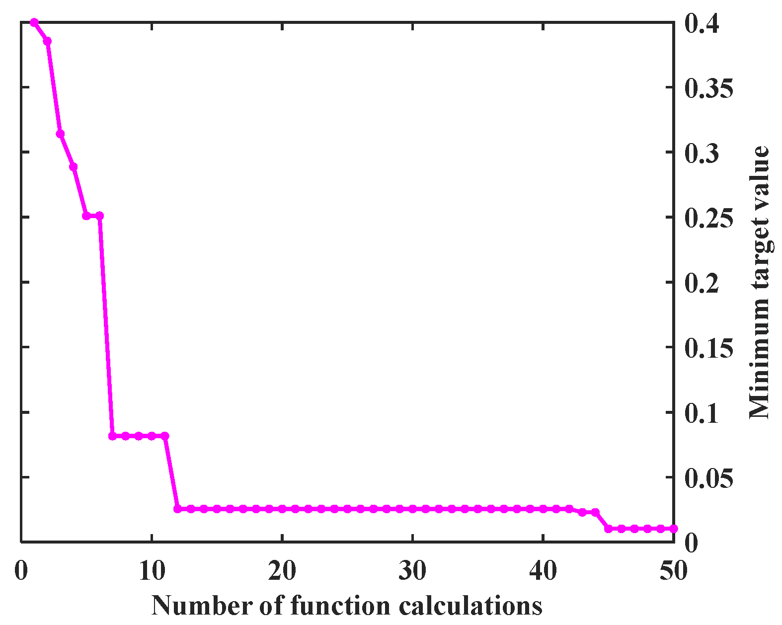
While additional iterations might yield further improvements, this study capped the budget at 50 to balance solution quality and computational cost. During the process, the surrogate function is continuously updated using a Gaussian Process model. The next sampling point is selected based on the expected improvement criterion, gradually approaching the optimal value of the objective function. The convergence curve of the objective function during optimization is shown in
Figure 3.
As shown in
Figure 2, the objective function value drops rapidly within the first 20 evaluations of the BO, demonstrating strong global search capability. By the 10th evaluation, the value falls below 0.05. Around the 30th iteration, the function value begins to stabilize, indicating that the algorithm is gradually converging toward the optimal region. The minimum value of the objective function, 0.0118, is reached at the 47th evaluation, suggesting that both global exploration and local refinement have been effectively completed. This result confirms that BO can achieve efficient convergence within a limited number of evaluations and shows excellent optimization performance. The corresponding optimal parameter set is listed in
Table 4.
3. Experimental and Result Analysis
Based on the BO results, the correction process at each stage was simulated using MATLAB 2016a. According to the proposed scheme, the simulation procedure is as follows: the initial attitude is set with an inclination and tool face of 1°, and an azimuth of 30°. The system remains stationary for 300 s to obtain approximate initial attitude information. Then, it rotates 180°, followed by another 250 s of static state, during which data backtracking is performed 3 times. Next, single-axis continuous rotation is conducted. The system performs 10 clockwise rotations at a constant speed within 250 s. Finally, it enters a static state for 350 s, during which data backtracking is again performed 3 times. The total simulation time is 1150 s. The simulated attitude variation and data backtracking process are shown in
Figure 4. In all subsequent plots, the backtracking periods are fully expanded.
After completing the simulation of the attitude data, the attitude data is converted to gyro data and accelerometer data. Then the error is added, and the added error is shown in
Table 5 below:
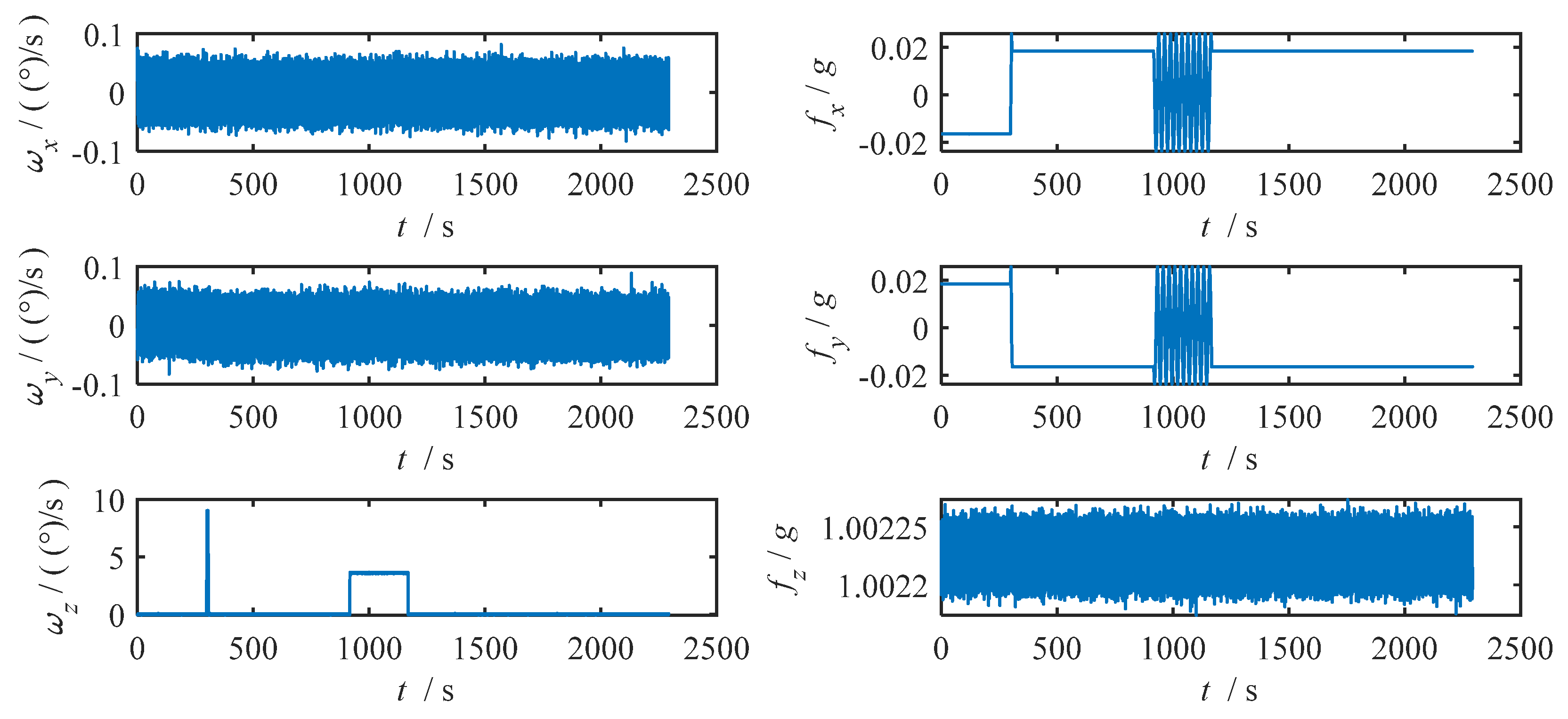
The original data of the gyroscope and accelerometer obtained by simulation are shown in
Figure 5.
The simulated gyroscope and accelerometer data are corrected for systematic errors, and the corrected attitude and attitude error results are shown in
Figure 6.
In
Figure 6, the blue curve represents the corrected attitude results, while the pink curve shows the error between the estimated attitude and the true value. It can be observed that the inclination and tool face converge rapidly and become closer to the true values after the dual-position rotation. The azimuth error gradually decreases after both the two-position and single-axis continuous rotations, indicating that these procedures effectively improve the accuracy of attitude alignment.
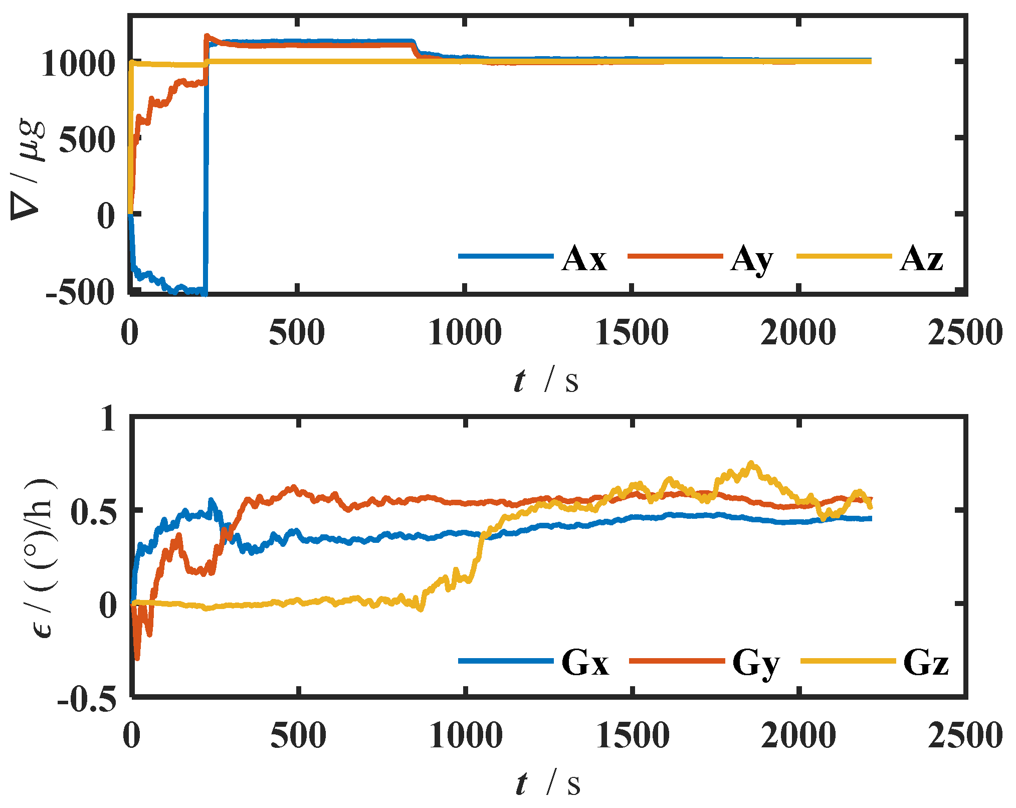
The estimated gyroscope bias and accelerometer bias during the system error correction process are shown in
Figure 7.
As shown in
Figure 7, after completing the two-position rotation, the gyroscope and accelerometer biases in the east and north directions quickly converge to the true value. After the single-axis continuous rotation, the vertical gyroscope bias is gradually estimated. Meanwhile, the accelerometer bias in the east and north directions becomes even closer to the true value, demonstrating the effectiveness of the proposed error correction method.
The proposed correction scheme was compared with a static scheme, a two-position rotation scheme, a multi-position rotation scheme, a single-axis continuous rotation scheme, and a Kalman filter scheme. The total error correction time for all schemes except the proposed scheme is 2350 s. The comparison results are shown in
Table 6.
Table 6 demonstrates the error comparison of the six error correction methods on the three attitude parameters. It can be seen that, except for the static method, all the schemes achieve high accuracy in pitch and tool face angle measurements. However, in the measurement accuracy of heading angle (Azimuth), the difference between the methods is obvious, reflecting that the system is more sensitive to the observability of this parameter. Among them, the heading angle error of the static method is as high as 1.2849°, which is far from meeting the requirements of engineering applications; while the proposed scheme significantly reduces the error to 0.0717°, which is an improvement of 94.42% compared with the static method. Although the two-position rotation, multi-position rotation, Continuous rotation, and Kalman filtering methods also achieve different degrees of enhancement (errors of 0.1590°, 0.1487°, 0.1135°, and 0.0951°, respectively), they are still inferior to the performance of this paper’s method in terms of maintaining system excitation and observability. This suggests that the proposed method can achieve more accurate heading estimation by enhancing the vertical gyro zero-bias observability, which has better practicality and engineering promotion value. The observability variation of each state variable under the single-axis rotation error correction scheme is shown in
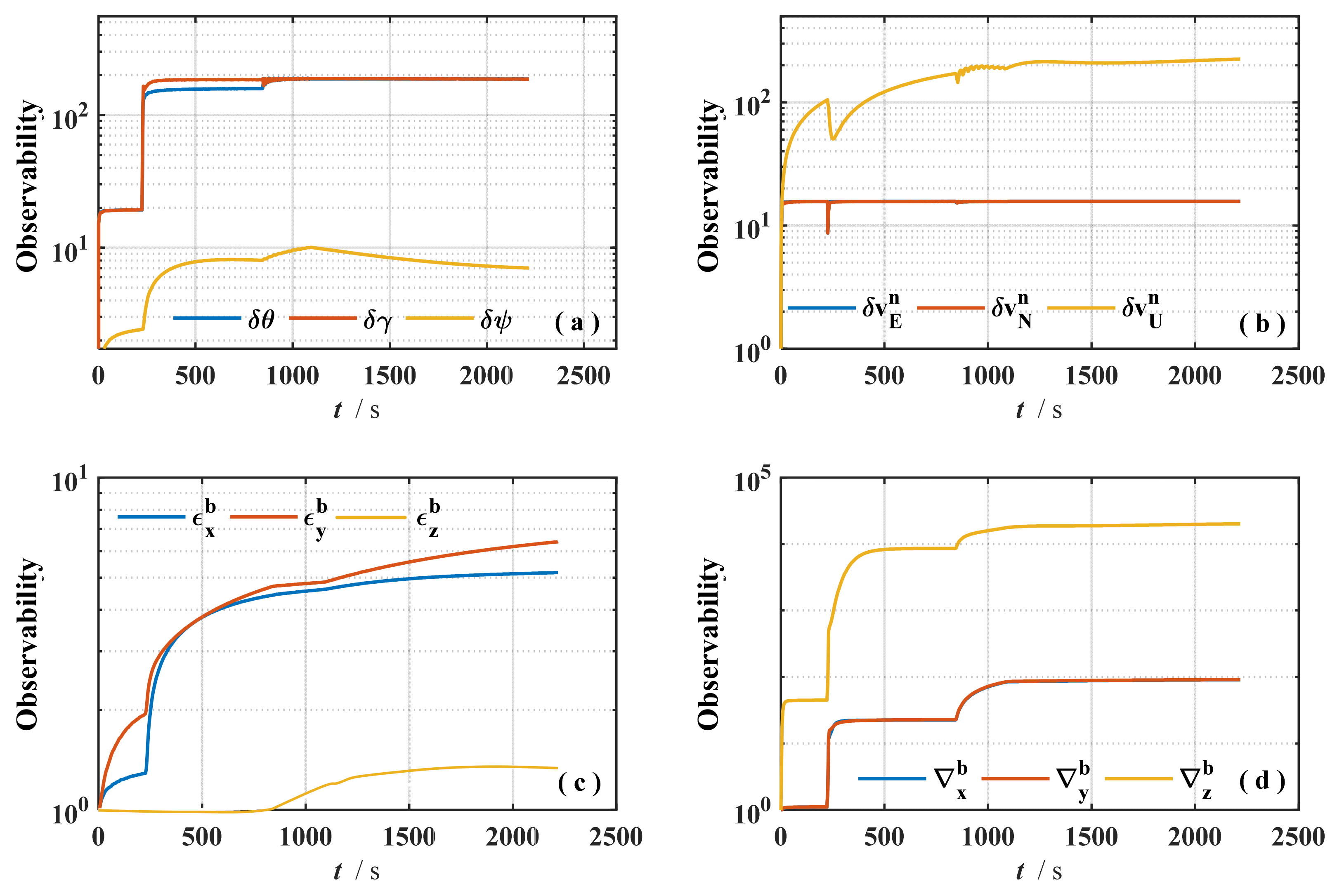
Figure 8.
In
Figure 8a, the observability of the attitude error increases rapidly at the beginning of the rotation and then remains stable. The observability improvement of the heading error is the most significant after the single-axis rotation.
Figure 8b shows the observability of the velocity error, where all three components exhibit strong observability. In
Figure 8c, for the gyroscope bias, the vertical component maintains low observability but improves from unobservable to weakly observable. The other two components reach high observability levels early during the rotation phase.
Figure 8d shows the observability of the accelerometer bias. After two-position and continuous single-axis rotation, the observability of all components improves to varying degrees. In summary, the rotational excitation significantly enhances the observability of system state variables, confirming the effectiveness of the proposed single-axis rotation-based error correction method in improving system observability.
4. Discussion
4.1. Validation of BO Effect
The online system error correction method based on single-axis rotation and data backtracking proposed in this study effectively improves the error observability and attitude estimation accuracy of the inertial navigation system. The scheme enables greater observability of the system states by introducing external excitation through the excitation of the rotational mechanism. Compared with the error correction method only in the stationary state, due to the limited data excitation acquired by the inertial navigation system in the stationary state, especially in the azimuth direction, no effective observation can be provided. As a result, the zero-bias term is difficult to fully estimate, leading to a larger uncertainty. The error correction method of single-axis rotation coupled with data retrospection significantly enhances the system excitation. Through data reuse, this method achieves more accurate error modelling and state solving, which substantially improves the alignment accuracy. Meanwhile, in order to further optimize the scheme, this study introduces a BO algorithm to globally search the key control parameters of the proposed scheme. The optimal combination is searched to achieve the optimal value of the objective function. In order to verify its effectiveness, two groups of manually set-up schemes (Scheme 1 and Scheme 2) are selected for comparison, and the specific control parameters are shown in
Table 7.
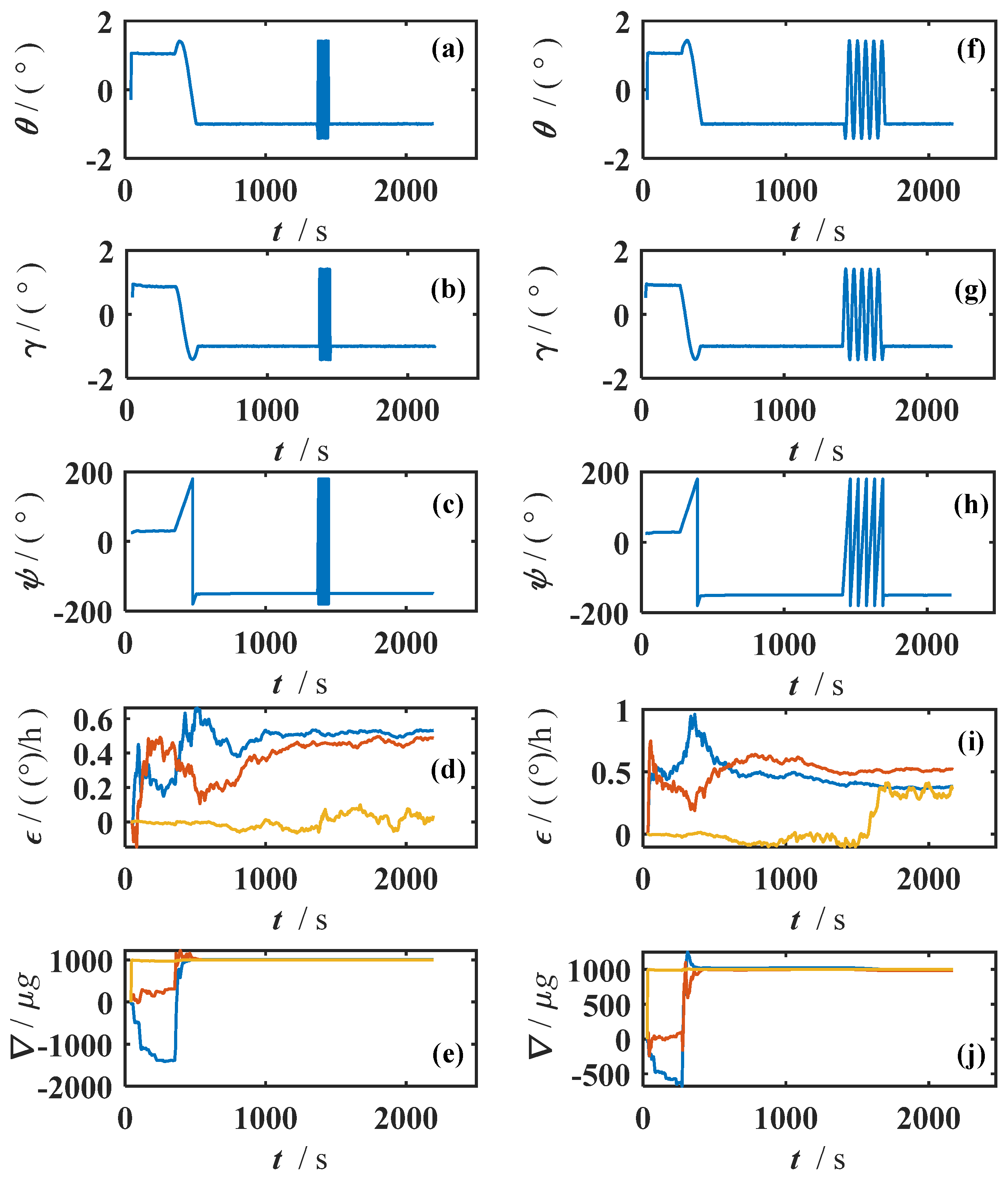
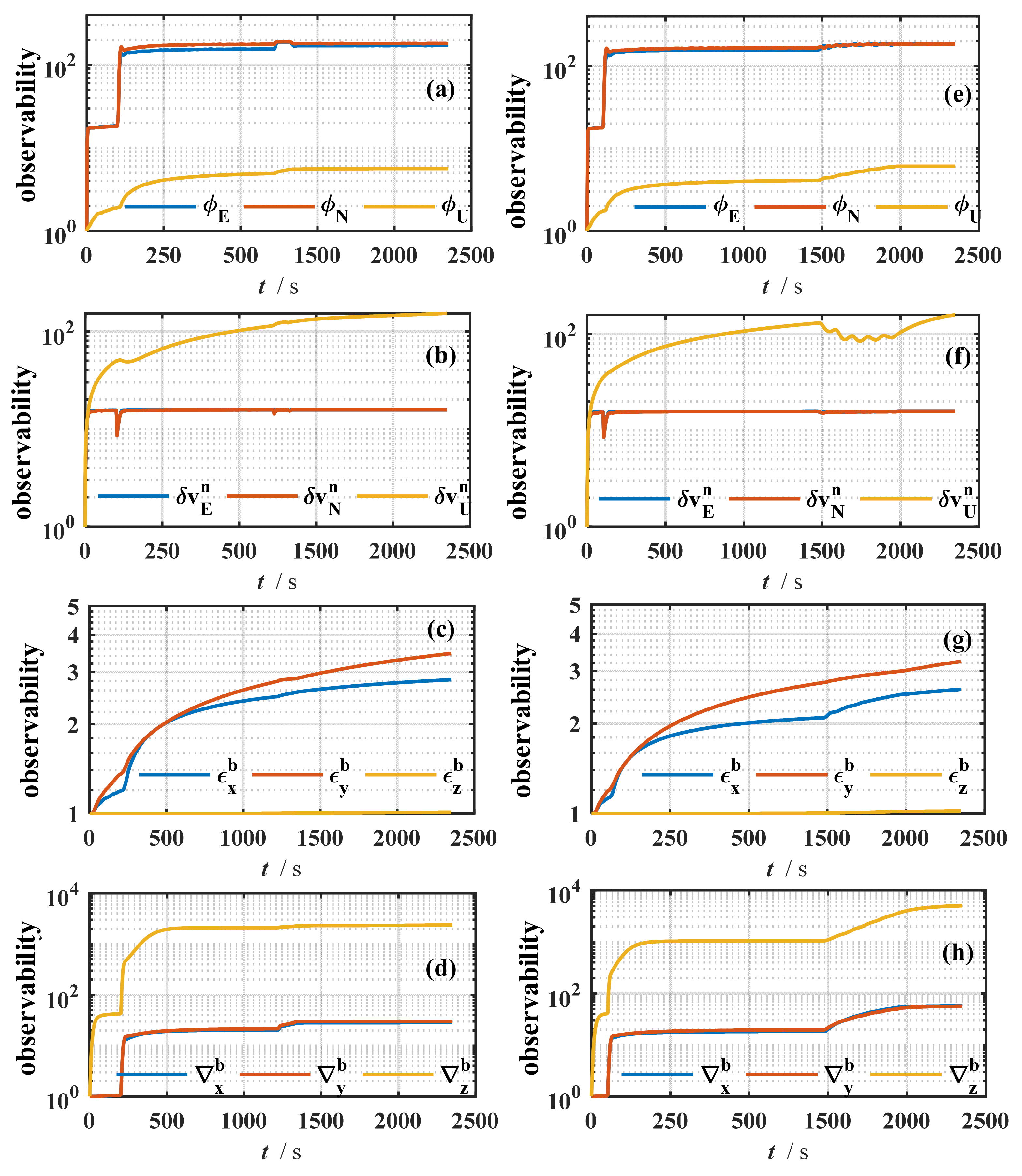
The error correction results of Scheme 1 and Scheme 2 are shown in
Figure 9 and
Figure 10.
Figure 9 shows the attitude estimation process under different schemes, including the attitude solution results, gyroscope zero bias, and accelerometer zero bias.
Figure 9 further gives the observability variation process of the corresponding parameters.
As can be seen in
Figure 9, compared with the manual setting scheme, the BO scheme shows obvious advantages in several indicators. At the beginning of the rotational excitation, the vertical gyroscope zero bias of the BO scheme converges rapidly to the true value with almost no obvious fluctuation. It shows that the optimized parameter combination not only improves the convergence speed of the filter but also enhances the robustness of the estimation process. In contrast, the gyroscope zero bias estimation in Scheme 1 suffers from a large drift and fails to stabilize even after a long period. The observability comparison results of Scheme 1 and Scheme 2 are shown in
Figure 10.
From the trend of observability changes in
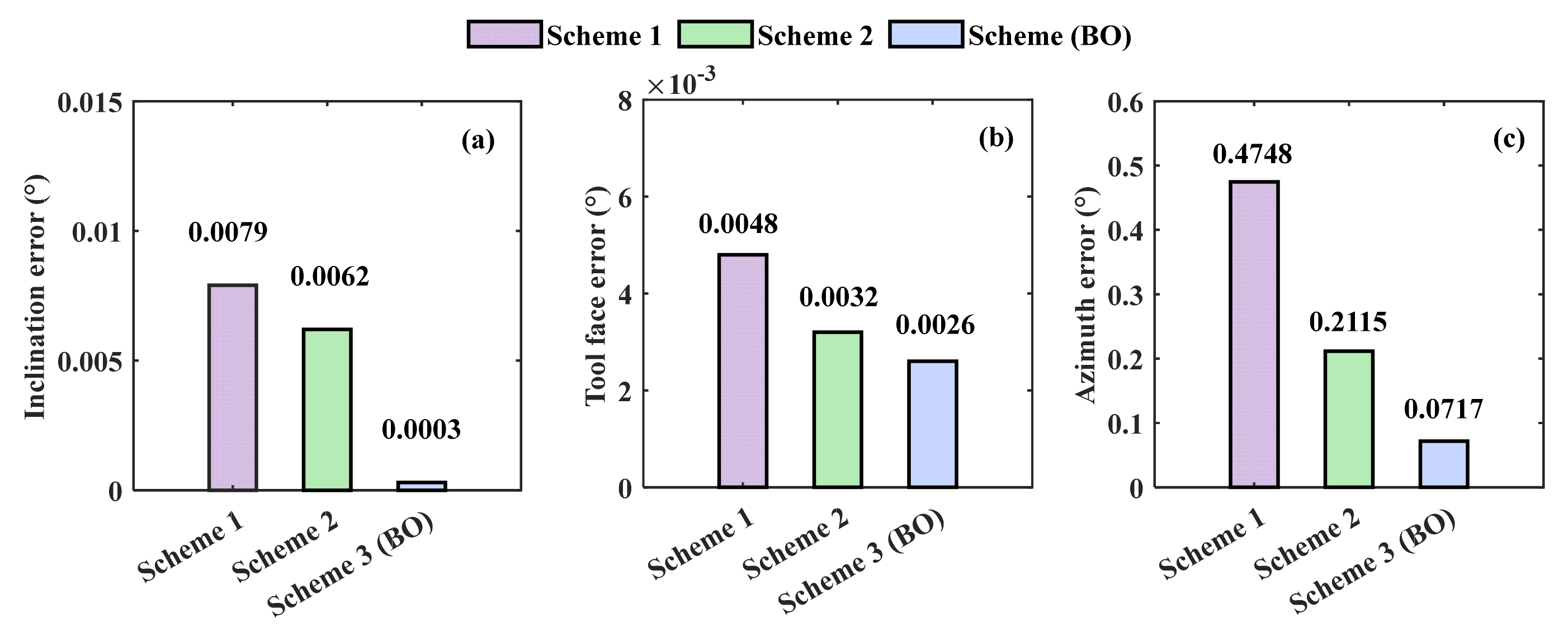
Figure 10, it can be seen that the observability of all states is improved in Scheme 1 and Scheme 2, except the observability of the vertical gyroscope zero bias is not improved. However, the improvement effect is weaker compared to the BO scheme. This proves the necessity of using the BO algorithm to optimize the key control parameters. To further quantify the differences in final state accuracy between the schemes, the final estimation error histograms for the three attitude angles are shown in
Figure 11.
In
Figure 11, the BO scheme achieves the minimum error in all three attitude directions. The inclination accuracy is improved by 96.20% compared to Scheme 1 and 95.16% compared to Scheme 2. The tool face accuracy is improved by 45.83% compared to Scheme 1 and 18.75% compared to Scheme 2. The azimuth accuracy is improved by 84.90% compared to Scheme 1 and 66.10% compared to Scheme 2. The results further validate the effectiveness of the BO algorithm in confirming the parameters of the rotation strategy.
The above analysis fully demonstrates that the system error correction performance of the proposed scheme is significantly affected by the configuration of key parameters. If the parameters are set manually, it is easy to cause unstable filtering performance and large fluctuations in the final attitude accuracy. By introducing the BO algorithm, the error estimation accuracy and convergence stability can not only be improved, but also the final output accuracy can be significantly improved.
4.2. System Feasibility and Complexity Analysis
The yellow curve in
Figure 8c shows the observability of the vertical gyroscope under the proposed method; it converges to about 1.5. According to Equation (11), this level corresponds to weak observability. Compared with the unobservable static case, the proposed scheme significantly improves the observability of the vertical gyroscope; based on the system error-propagation equations, the measurement information enables estimation of a large portion of the vertical gyro bias. In addition, the results of this study are based on simulation conditions with prescribed noise and motion profiles, and do not take into account field disturbances such as temperature gradients, vibration bursts, hydraulic transients, and unsteady duty cycles. In practical deployment, it is recommended that adaptive noise estimation and filtering be used to eliminate the effect of random systematic errors on measurement accuracy [
21].
The online cost is dominated by small dense linear algebra in the EKF: each predict-update step scales as ; with this is roughly 104–105 floating-point operations per cycle. At lMU rates of 100 Hz, the total load is smaller than 106 flops/s, i.e., lightweight for typical embedded CPUs. When a correction is triggered, a backtracking window of length N is replayed for at most r passes, adding work during those infrequent events, so the amortized overhead remains small. Memory scales as for EKF matrices plus for the buffer; with and N < 3000, this is only a few megabytes. BO is performed offline and does not affect runtime. Overall, the method is computationally lightweight and can run in real time during pipe-jacking on standard embedded hardware.
4.3. Real-World Deployment Scheme of the System
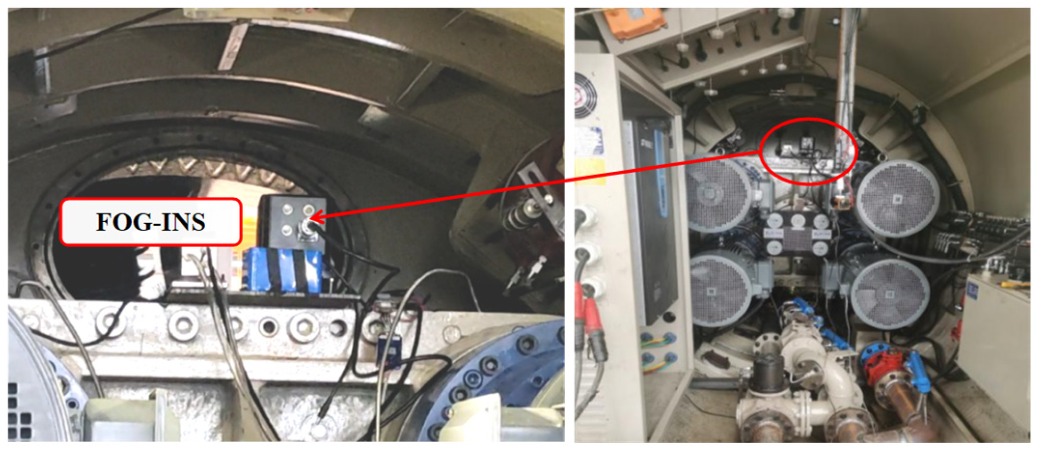
Currently, FOG-INS has been able to conduct real-time data acquisition experiments in the practical pipe jacking machine, but the corresponding single-axis rotary stage has not been built yet, as shown in
Figure 12.
It is verified that FOG-INS can work in the environment of a real pipe jacking machine, but it needs to be corrected for its systematic error. Therefore, for the online error calibration scheme proposed in this study, the deployment scheme of the real project is as follows.
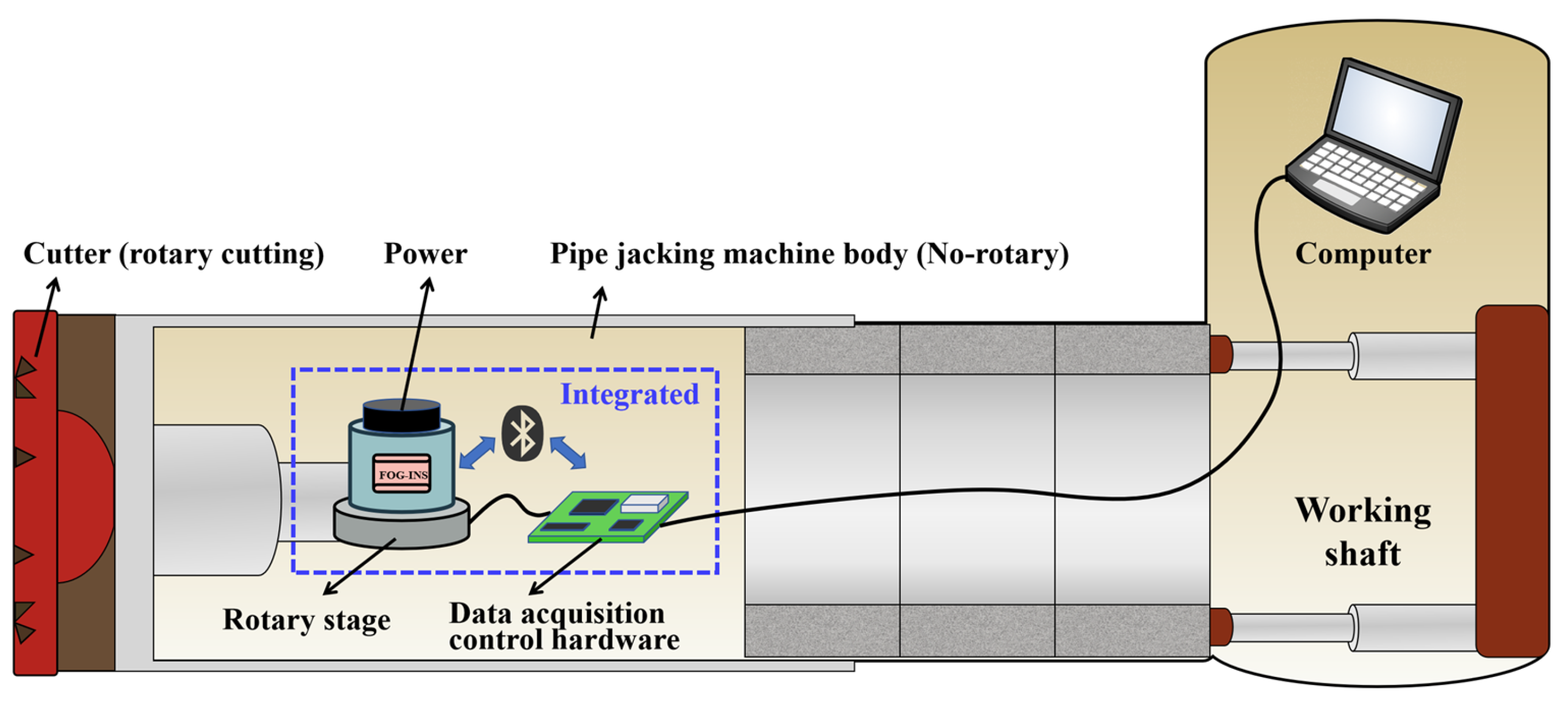
(1) Hardware components
The system consists of a FOG-INS, power supply, single-axis rotary stage, data acquisition and control hardware, and a host computer. The FOG-INS, rotary stage, and acquisition/control hardware are integrated into a single compact module mounted behind the cutterhead of the pipe-jacking machine. This module is connected to the host computer located in the working shaft via cable.
(2) Communication scheme
Since the FOG-INS requires rotational movement, traditional data cables are prone to tangling. Therefore, Bluetooth communication is adopted for data transmission between the FOG-INS and the data acquisition/control hardware. Wired connections are used between the rotary stage and the acquisition/control hardware, as well as between the acquisition/control unit and the host computer.
(3) Operating procedure
Step 1: Upon power-up, the FOG-INS begins broadcasting data via Bluetooth to the acquisition/control hardware.
Step 2: The acquisition module receives the data and forwards it to the host computer.
Step 3: Once communication is confirmed, the host computer sends a command to trigger the single-axis rotation and initiate the error calibration process.
Step 4: The acquisition/control hardware executes the predefined rotation scheme and performs the embedded correction algorithm.
Step 5: The correction results are transmitted in real time to the host computer for status display and data logging.
The deployment diagram of the proposed online correction method for system errors in the pipe-jacking inertial guidance system is shown in
Figure 13.
5. Conclusions
In this study, a systematic error online correction method integrating single-axis rotary excitation and data retrospective technology is proposed to address the problems of low accuracy and long error correction time of the inertial navigation system in pipe jacking construction. The key parameters are optimally configured by combining the BO algorithm. Firstly, an error model and observability analysis framework are established for the pipe jacking inertial guidance system, and the state identification capability is improved by rotational excitation. It can significantly improve the error estimation accuracy while ensuring the simplification of the construction process. Secondly, in order to further improve the system error correction effect, a BO algorithm is used to perform multi-objective optimization on the key control parameters, which verifies its effectiveness in improving the system accuracy, accelerating the system convergence, and enhancing the stability. Finally, the experimental results show that the optimized scheme proposed in this study has an inclination error of 0.0003°, a tool face error of 0.0026°, and an azimuth error of 0.0717° under the correction time of 1250 s, which is significantly better than the stationary state. Compared with the non-optimized scheme, the azimuth accuracy of the scheme proposed in this study is improved by 84.90% compared with Scheme 1 and 66.10% compared with Scheme 2. In summary, the proposed online system error correction scheme has the advantages of fast correction, no need for high-precision equipment, and high accuracy of attitude measurement. It is suitable for the demand of online correction of inertial navigation system error for pipe jacking, and has good engineering promotion.
